

Ricoh Af 2015 Service Manual

Model K-C2
(Machine Code: B121/B122/B123)
SERVICE MANUAL
December 1st, 2003
Subject to change

!IMPORTANT SAFETY NOTICES
PREVENTION OF PHYSICAL INJURY
1. Before disassembling or assembling parts of the copier and peripherals,
make sure that the power cord is unplugged.
2. The wall outlet should be near the copier and easily accessible.
3. Note that some components of the copier and the paper tray unit are
supplied with electrical voltage even if the main power switch is turned off.
4. If a job has started before the copier completes the warm-up or initializing
period, keep hands away from the mechanical and electrical components
because the starts making copies as soon as the warm-up period is
completed.
5. The inside and the metal parts of the fusing unit become extremely hot while
the copier is operating. Be careful to avoid touching those components with
your bare hands.
HEALTH SAFETY CONDITIONS
Toner and developer are non-toxic, but if you get either of them in your eyes by
accident, it may cause temporary eye discomfort. Try to remove with eye drops
or flush with water as first aid. If unsuccessful, get medical attention.
OBSERVANCE OF ELECTRICAL SAFETY STANDARDS
The copier and its peripherals must be installed and maintained by a customer
service representative who has completed the training course on those models.
SAFETY AND ECOLOGICAL NOTES FOR DISPOSAL
1. Do not incinerate toner bottles or used toner. Toner dust may ignite suddenly
when exposed to an open flame.
2. Dispose of used toner, developer, and organic photoconductors in
accordance with local regulations. (These are non-toxic supplies.)
3. Dispose of replaced parts in accordance with local regulations.

LASER SAFETY
The Center for Devices and Radiological Health (CDRH) prohibits the repair of
laser-based optical units in the field. The optical housing unit can only be repaired
in a factory or at a location with the requisite equipment. The laser subsystem is
replaceable in the field by a qualified Customer Engineer. The laser chassis is not
repairable in the field. Customer engineers are therefore directed to return all
chassis and laser subsystems to the factory or service depot when replacement of
the optical subsystem is required.
!WARNING
Use of controls, or adjustment, or performance of procedures other than
those specified in this manual may result in hazardous radiation exposure.
!WARNING FOR LASER UNIT
WARNING: Turn off the main switch before attempting any of the
procedures in the Laser Unit section. Laser beams can
seriously damage your eyes.
CAUTION MARKING:
Symbols and Abbreviations
This manual uses several symbols and abbreviations. The meaning of those
symbols and abbreviations are as follows:
☛
!
"
#
SEF
LEF
See or Refer to
Clip ring
Screw
Connector
Short Edge Feed
Long Edge Feed

TABLE OF CONTENTS
1. INSTALLATION........................................................................... 1-1
1.1 INSTALLATION REQUIREMENTS........................................................... 1-1
1.1.1 ENVIRONMENT .............................................................................. 1-1
1.1.2 MACHINE LEVEL ............................................................................ 1-2
1.1.3 MINIMUM SPACE REQUIREMENTS.............................................. 1-3
1.1.4 POWER REQUIREMENTS.............................................................. 1-3
1.2 COPIER INSTALLATION.......................................................................... 1-4
1.2.1 POWER SOCKETS FOR PERIPHERALS....................................... 1-4
1.2.2 ACCESSORY CHECK..................................................................... 1-4
1.2.3 INSTALLATION PROCEDURE........................................................ 1-5
1.3 PLATEN COVER INSTALLATION............................................................ 1-8
1.3.1 ACCESSORY CHECK..................................................................... 1-8
1.3.2 INSTALLATION PROCEDURE........................................................ 1-8
1.4 ARDF INSTALLATION.............................................................................. 1-9
1.4.1 ACCESSORY CHECK..................................................................... 1-9
1.4.2 INSTALLATION PROCEDURE........................................................ 1-9
1.5 ADF INSTALLATION .............................................................................. 1-12
1.5.1 ACCESSORY CHECK................................................................... 1-12
1.5.2 INSTALLATION PROCEDURE...................................................... 1-12
1.6 TWO-TRAY PAPER TRAY UNIT INSTALLATION ................................. 1-15
1.6.1 ACCESSORY CHECK................................................................... 1-15
1.6.2 INSTALLATION PROCEDURE...................................................... 1-15
1.7 ONE-TRAY PAPER TRAY UNIT INSTALLATION.................................. 1-19
1.7.1 ACCESSORY CHECK................................................................... 1-19
1.7.2 INSTALLATION PROCEDURE...................................................... 1-19
1.8 ONE-BIN TRAY INSTALLATION............................................................ 1-22
1.8.1 ACCESSORY CHECK................................................................... 1-22
1.8.2 INSTALLATION PROCEDURE...................................................... 1-22
1.9 ANTI-CONDENSATION HEATER INSTALLATION................................ 1-25
1.10 TRAY HEATERS .................................................................................. 1-26
1.10.1 UPPER TRAY HEATER............................................................... 1-26
1.10.2 LOWER TRAY HEATER (TWO-TRAY MODEL ONLY)............... 1-27
1.10.3 TRAY HEATERS FOR THE OPTIONAL PAPER FEED UNITS .. 1-28
1.11 KEY COUNTER INSTALLATION.......................................................... 1-31
1.12 MFP EXPANSION ................................................................................ 1-33
1.12.1 ACCESSORY CHECK................................................................. 1-34
1.12.2 INSTALLING EXPANSION COMPONENT.................................. 1-35
Step 1–Controller Box ........................................................................ 1-35
Step 2–Printer/Scanner...................................................................... 1-36
Step 3–PostScript .............................................................................. 1-36
Step 4–Fax......................................................................................... 1-37
Step 5–Reassembling........................................................................ 1-37
1.12.3 INSTALLING PANELS AND KEYS.............................................. 1-37
Step 6–Panel...................................................................................... 1-37
Step 7–Printer/Scanner Keys............................................................. 1-38
i

Step 8–Fax Keys................................................................................ 1-38
Step 9–Printer/Scanner and Fax Keys............................................... 1-39
1.12.4 SETTINGS................................................................................... 1-40
Step 10–MFP Settings and Time Settings ......................................... 1-40
Step 11–Fax Settings......................................................................... 1-40
1.13 IEEE1284/IEEE1394 INTERFACE ....................................................... 1-41
1.13.1 ACCESSORY CHECK................................................................. 1-42
1.13.2 INSTALLATION PROCEDURE.................................................... 1-42
UP Mode Settings for Wireless LAN .................................................. 1-44
SP Mode Settings for IEEE 802.11b Wireless LAN............................ 1-45
1.14 BLUETOOTH........................................................................................ 1-46
1.14.1 ACCESSORY CHECK................................................................. 1-46
1.14.2 INSTALLATION PROCEDURE.................................................... 1-46
2. PREVENTIVE MAINTENANCE................................................... 2-1
2.1 PM TABLES.............................................................................................. 2-1
Optics................................................................................................... 2-1
Drum Area............................................................................................ 2-1
Paper Feed .......................................................................................... 2-1
Fusing Unit........................................................................................... 2-2
ADF/ARDF ........................................................................................... 2-2
Paper Tray Unit.................................................................................... 2-2
2.2 HOW TO RESET THE PM COUNTER..................................................... 2-3
3. REPLACEMENT AND ADJUSTMENT........................................ 3-1
3.1 GENERAL CAUTIONS ............................................................................. 3-1
3.1.1 PCU (PHOTOCONDUCTOR UNIT)................................................. 3-1
3.1.2 TRANSFER ROLLER ...................................................................... 3-1
3.1.3 SCANNER UNIT .............................................................................. 3-1
3.1.4 LASER UNIT.................................................................................... 3-2
3.1.5 FUSING UNIT.................................................................................. 3-2
3.1.6 PAPER FEED .................................................................................. 3-2
3.1.7 IMPORTANT.................................................................................... 3-2
3.2 SPECIAL TOOLS AND LUBRICANTS ..................................................... 3-3
3.3 EXTERIOR COVERS & OPERATION PANEL ......................................... 3-4
3.3.1 REAR COVER ................................................................................. 3-4
3.3.2 REAR LOWER COVER (TWO-TRAY MODELS ONLY).................. 3-4
3.3.3 COPY TRAY .................................................................................... 3-5
3.3.4 UPPER COVERS ............................................................................ 3-5
3.3.5 LEFT COVER .................................................................................. 3-6
3.3.6 FRONT COVER............................................................................... 3-6
3.3.7 FRONT RIGHT COVER................................................................... 3-7
3.3.8 RIGHT REAR COVER..................................................................... 3-7
3.3.9 RIGHT DOOR (B121/B122)/DUPLEX UNIT (B123)......................... 3-8
3.3.10 BY-PASS TRAY............................................................................. 3-9
3.3.11 LEFT LOWER COVER (TWO-TRAY MODELS ONLY) ............... 3-10
3.3.12 RIGHT LOWER COVER (TWO-TRAY MODELS ONLY)............. 3-10
3.3.13 PLATEN COVER SENSOR ......................................................... 3-10
ii

3.4 SCANNER UNIT..................................................................................... 3-11
3.4.1 EXPOSURE GLASS/DF EXPOSURE GLASS............................... 3-11
Exposure Glass.................................................................................. 3-11
DF Exposure Glass............................................................................ 3-11
3.4.2 LENS BLOCK ................................................................................ 3-12
3.4.3 LAMP STABILIZER BOARD AND EXPOSURE LAMP.................. 3-12
3.4.4 ORIGINAL WIDTH/LENGTH SENSOR ......................................... 3-13
Sensor Positions ................................................................................ 3-13
Sensor Positions for China Model (8K/16K)....................................... 3-14
3.4.5 SCANNER MOTOR ....................................................................... 3-15
3.4.6 SCANNER HOME POSITION SENSOR ....................................... 3-15
3.4.7 ADJUSTING SCANNER POSITIONS............................................ 3-16
Overview ............................................................................................ 3-16
Adjusting the First Scanner Contact Points........................................ 3-17
Adjusting the Second Scanner Contact Points................................... 3-18
3.5 LASER UNIT........................................................................................... 3-19
3.5.1 LOCATION OF CAUTION DECAL................................................. 3-19
3.5.2 TONER SHIELD GLASS................................................................ 3-20
3.5.3 LASER UNIT.................................................................................. 3-20
3.5.4 LD UNIT......................................................................................... 3-21
3.5.5 POLYGONAL MIRROR MOTOR................................................... 3-21
3.5.6 LASER UNIT ALIGNMENT ADJUSTMENT................................... 3-22
3.6 PCU SECTION ....................................................................................... 3-23
3.6.1 PCU ............................................................................................... 3-23
3.6.2 PICK-OFF PAWLS AND TONER DENSITY SENSOR .................. 3-23
3.6.3 OPC DRUM ................................................................................... 3-24
3.6.4 CHARGE ROLLER AND CLEANING BRUSH............................... 3-25
3.6.5 CLEANING BLADE........................................................................ 3-25
3.6.6 DEVELOPER................................................................................. 3-26
3.6.7 AFTER REPLACEMENT OR ADJUSTMENT................................ 3-27
3.7 TONER SUPPLY MOTOR...................................................................... 3-28
3.8 PAPER FEED SECTION ........................................................................ 3-28
3.8.1 PAPER FEED ROLLER................................................................. 3-28
3.8.2 FRICTION PAD.............................................................................. 3-28
3.8.3 PAPER END SENSOR.................................................................. 3-29
3.8.4 EXIT SENSOR............................................................................... 3-29
Non-duplex Models ............................................................................ 3-29
Duplex Models ................................................................................... 3-29
3.8.5 BY-PASS FEED ROLLER AND PAPER END SENSOR ............... 3-30
3.8.6 REGISTRATION ROLLER............................................................. 3-31
3.8.7 BY-PASS PAPER SIZE SWITCH .................................................. 3-32
3.8.8 REGISTRATION CLUTCH............................................................. 3-32
3.8.9 REGISTRATION SENSOR............................................................ 3-33
3.8.10 UPPER PAPER FEED CLUTCH AND BY-PASS FEED CLUTCH3-33
3.8.11 RELAY CLUTCH.......................................................................... 3-34
3.8.12 RELAY SENSOR......................................................................... 3-34
3.8.13 LOWER PAPER FEED CLUTCH (TWO-TRAY MODELS ONLY) 3-34
3.8.14 VERTICAL TRANSPORT SENSOR
(TWO-TRAY MODELS ONLY) .................................................... 3-35
iii

v
3.8.15 PAPER SIZE SWITCH................................................................. 3-35
3.9 IMAGE TRANSFER................................................................................ 3-36
3.9.1 IMAGE TRANSFER ROLLER........................................................ 3-36
3.9.2 IMAGE DENSITY SENSOR........................................................... 3-36
3.10 FUSING ................................................................................................ 3-37
3.10.1 FUSING UNIT.............................................................................. 3-37
3.10.2 THERMISTOR ............................................................................. 3-37
3.10.3 FUSING LAMPS .......................................................................... 3-38
3.10.4 HOT ROLLER STRIPPER PAWLS.............................................. 3-38
3.10.5 HOT ROLLER.............................................................................. 3-39
3.10.6 THERMOSTAT ............................................................................ 3-39
3.10.7 PRESSURE ROLLER AND BUSHINGS...................................... 3-40
3.10.8 NIP BAND WIDTH ADJUSTMENT .............................................. 3-41
3.10.9 CLEANING ROLLER ................................................................... 3-42
3.11 DUPLEX UNIT (DUPLEX MODELS ONLY).......................................... 3-43
3.11.1 DUPLEX EXIT SENSOR.............................................................. 3-43
3.11.2 DUPLEX ENTRANCE SENSOR.................................................. 3-43
3.11.3 DUPLEX INVERTER SENSOR ................................................... 3-44
3.11.4 DUPLEX TRANSPORT MOTOR ................................................. 3-45
3.11.5 DUPLEX INVERTER MOTOR ..................................................... 3-45
3.11.6 DUPLEX CONTROL BOARD ...................................................... 3-45
3.12 OTHER REPLACEMENTS................................................................... 3-46
3.12.1 QUENCHING LAMP .................................................................... 3-46
3.12.2 HIGH-VOLTAGE POWER SUPPLY BOARD............................... 3-46
3.12.3 BICU (BASE-ENGINE IMAGE CONTROL UNIT) ........................ 3-47
3.12.4 MAIN MOTOR.............................................................................. 3-47
3.12.5 REAR EXHAUST FAN (B123 ONLY) .......................................... 3-48
3.12.6 LEFT EXHAUST FAN.................................................................. 3-48
3.12.7 PSU (POWER SUPPLY UNIT) .................................................... 3-48
3.12.8 GEARBOX ................................................................................... 3-49
Replacement Procedure .................................................................... 3-49
Gear Arrangement in the Gearbox..................................................... 3-51
3.13 COPY ADJUSTMENTS: PRINTING/SCANNING ................................. 3-52
3.13.1 PRINTING.................................................................................... 3-52
Registration - Leading Edge/Side-to-Side .......................................... 3-52
Blank Margin ...................................................................................... 3-53
Main Scan Magnification.................................................................... 3-53
3.13.2 SCANNING.................................................................................. 3-54
Registration: Platen Mode.................................................................. 3-54
Magnification...................................................................................... 3-54
Standard White Density Adjustment................................................... 3-55
3.13.3 ADF IMAGE ADJUSTMENT ........................................................ 3-56
Registration and Blank Margin ........................................................... 3-56
Sub-scan Magnification...................................................................... 3-56
4. TROUBLESHOOTING................................................................. 4-1
4.1 SERVICE CALL CONDITIONS................................................................. 4-1
4.1.1 SUMMARY....................................................................................... 4-1
4.1.2 SC CODE DESCRIPTIONS............................................................. 4-2
i

v
4.2 ELECTRICAL COMPONENT DEFECTS................................................ 4-12
4.2.1 SENSORS ..................................................................................... 4-12
4.2.2 SWITCHES.................................................................................... 4-14
4.3 BLOWN FUSE CONDITIONS................................................................. 4-14
4.4 LED DISPLAY......................................................................................... 4-15
4.4.1 BICU .............................................................................................. 4-15
5. SERVICE TABLES...................................................................... 5-1
5.1 SERVICE PROGRAM MODE................................................................... 5-1
5.1.1 USING SP MODE............................................................................ 5-1
Starting SP Mode................................................................................. 5-1
Starting SSP Mode............................................................................... 5-2
Selecting Programs.............................................................................. 5-2
Specifying Values................................................................................. 5-2
Activating Copy Mode .......................................................................... 5-2
Quitting Programs/Ending (S)SP Mode................................................ 5-2
5.1.2 SP MODE TABLES–BASIC............................................................. 5-3
SP1-XXX (Feed) .................................................................................. 5-3
SP2-XXX (Drum).................................................................................. 5-6
SP4-XXX (Scanner) ........................................................................... 5-11
SP5-XXX (Mode)................................................................................ 5-16
SP6-XXX (Peripherals) ...................................................................... 5-19
SP7-XXX (Data Log) .......................................................................... 5-20
SP8-XXX (History) ............................................................................. 5-24
5.1.3 SP MODE TABLES–MFP.............................................................. 5-27
SP1-XXX (Feed) ................................................................................ 5-27
SP2-XXX (Drum)................................................................................ 5-30
SP4-XXX (Scanner) ........................................................................... 5-34
SP5-XXX (Mode)................................................................................ 5-41
SP6-XXX (Peripherals) ...................................................................... 5-54
SP7-XXX (Data Log) .......................................................................... 5-55
SP8-XXX (History) ............................................................................. 5-60
SP9-XXX (Etc.) .................................................................................. 5-71
5.1.4 ADJUSTING REGISTRATION AND MAGNIFICATION................. 5-73
5.1.5 ID SENSOR ERROR ANALYSIS (SP2-221).................................. 5-74
5.1.6 DISPLAY APS DATA (SP4-301-1)................................................. 5-75
Sensor Positions ................................................................................ 5-75
Reading the Data ............................................................................... 5-75
5.1.7 MEMORY CLEAR.......................................................................... 5-76
Basic Machine and MFP Machine...................................................... 5-76
Exceptions.......................................................................................... 5-76
With Flash Memory Card (Basic Machine Only)................................. 5-77
Without Flash Memory Card............................................................... 5-77
5.1.8 INPUT CHECK (SP5-803) ............................................................. 5-78
Conducting an Input Check................................................................ 5-78
Input Check Table.............................................................................. 5-78
5.1.9 OUTPUT CHECK (SP5-804) ......................................................... 5-80
Conducting an Output Check ............................................................. 5-80
Output Check Table ........................................................................... 5-80

5.1.10 SERIAL NUMBER INPUT (SP5-811)........................................... 5-81
Specifying Characters........................................................................ 5-81
Serial Number and NVRAM ............................................................... 5-81
5.1.11 NVRAM DATA UPLOAD/DOWNLOAD (SP5-824/825) ............... 5-82
Overview ............................................................................................ 5-82
NVRAM Upload (SP5-824-1) ............................................................. 5-82
NVRAM Download (SP5-825-1)......................................................... 5-83
5.1.12 FIRMWARE UPDATE PROCEDURE FOR BASIC MACHINES .. 5-84
5.1.13 TEST PATTERN PRINT (SP5-902-1).......................................... 5-85
Executing Test Pattern Printing.......................................................... 5-85
Test Patterns...................................................................................... 5-85
5.1.14 COUNTER–EACH PAPER JAM (SP7-504)................................. 5-86
5.1.15 SMC PRINT (SP5-990)................................................................ 5-87
5.1.16 ORIGINAL JAM HISTORY DISPLAY (SP7-508) ......................... 5-88
Viewing the Copy Jam History ........................................................... 5-88
Jam History Code............................................................................... 5-88
5.1.17 ADF APS SENSOR OUTPUT DISPLAY (SP6-901) .................... 5-89
Sensor Positions ................................................................................ 5-89
Reading Data ..................................................................................... 5-89
5.2 FIRMWARE UPDATE PROCEDURE FOR MFP MACHINES................ 5-90
5.2.1 BEFORE YOU BEGIN…................................................................ 5-90
5.2.2 FIRMWARE UPDATE PROCEDURE FOR MFP MACHINES ....... 5-91
5.2.3 NVRAM DATA UPLOAD/DOWNLOAD.......................................... 5-95
Uploading Content of NVRAM to an SD card..................................... 5-95
Downloading an SD Card to NVRAM................................................. 5-95
6. DETAILED SECTION DESCRIPTIONS....................................... 6-1
6.1 OVERVIEW .............................................................................................. 6-1
6.1.1 COMPONENT LAYOUT .................................................................. 6-1
6.1.2 PAPER PATH .................................................................................. 6-3
6.1.3 DRIVE LAYOUT............................................................................... 6-4
6.2 BOARD STRUCTURE.............................................................................. 6-5
6.2.1 BLOCK DIAGRAM........................................................................... 6-5
1. BICU (Base Engine and Image Control Unit)..................................... 6-6
2. SBU (Sensor Board Unit)................................................................... 6-6
6.3 COPY PROCESS OVERVIEW................................................................. 6-7
6.4 SCANNING............................................................................................... 6-9
6.4.1 OVERVIEW...................................................................................... 6-9
Lamp Stabilizer Fuse ........................................................................... 6-9
6.4.2 SCANNER DRIVE ......................................................................... 6-10
6.4.3 ORIGINAL SIZE DETECTION IN PLATEN MODE ........................ 6-11
6.5 IMAGE PROCESSING ........................................................................... 6-13
6.5.1 OVERVIEW.................................................................................... 6-13
6.5.2 SBU (SENSOR BOARD UNIT)...................................................... 6-14
6.5.3 IPU (IMAGE PROCESSING UNIT)................................................ 6-15
Overview ............................................................................................ 6-15
Image Processing Modes................................................................... 6-16
Image Processing Path ...................................................................... 6-17
Original Modes................................................................................... 6-18
vi

SP Modes for Each Image Processing Step ...................................... 6-18
Auto Shading...................................................................................... 6-20
White Line Erase................................................................................ 6-21
Black Line Erase ................................................................................ 6-21
Auto image density (ADS).................................................................. 6-22
Scanner Gamma (γ) Correction.......................................................... 6-23
Main Scan Magnification.................................................................... 6-24
Mirroring for ADF Mode...................................................................... 6-24
Filtering .............................................................................................. 6-25
ID Gamma (γ) Correction ................................................................... 6-26
Gradation Processing......................................................................... 6-27
6.5.4 VIDEO CONTROL UNIT (VCU)..................................................... 6-28
Fine Character and Image (FCI) ........................................................ 6-28
Printer Gamma Correction ................................................................. 6-28
6.6 LASER EXPOSURE ............................................................................... 6-29
6.6.1 OVERVIEW.................................................................................... 6-29
6.6.2 AUTO POWER CONTROL (APC) ................................................. 6-30
6.6.3 LD SAFETY SWITCH .................................................................... 6-31
6.7 PHOTOCONDUCTOR UNIT (PCU)........................................................ 6-32
6.7.1 OVERVIEW.................................................................................... 6-32
6.7.2 DRIVE............................................................................................ 6-33
6.8 DRUM CHARGE..................................................................................... 6-34
6.8.1 OVERVIEW.................................................................................... 6-34
6.8.2 CHARGE ROLLER VOLTAGE CORRECTION ............................. 6-35
Correction for Environmental Conditions............................................ 6-35
6.8.3 ID SENSOR PATTERN PRODUCTION TIMING........................... 6-36
6.8.4 DRUM CHARGE ROLLER CLEANING ......................................... 6-37
6.9 DEVELOPMENT..................................................................................... 6-38
6.9.1 OVERVIEW.................................................................................... 6-38
6.9.2 DRIVE............................................................................................ 6-39
6.9.3 DEVELOPER MIXING ................................................................... 6-39
6.9.4 DEVELOPMENT BIAS................................................................... 6-40
6.9.5 TONER SUPPLY ........................................................................... 6-41
Toner Bottle Replenishment Mechanism ........................................... 6-41
Toner Supply Mechanism................................................................... 6-42
6.9.6 TONER DENSITY CONTROL ....................................................... 6-43
Overview ............................................................................................ 6-43
Toner Density Sensor Initial Setting................................................... 6-45
Toner Concentration Measurement.................................................... 6-45
Vsp/Vsg Detection.............................................................................. 6-45
Toner Supply Reference Voltage (Vref) Determination...................... 6-45
Toner Supply Determination............................................................... 6-45
Toner Supply Motor On Time Determinations.................................... 6-46
6.9.7 TONER SUPPLY IN ABNORMAL SENSOR CONDITIONS .......... 6-47
ID Sensor ........................................................................................... 6-47
TD Sensor.......................................................................................... 6-47
vii

6.9.8 TONER NEAR END/END DETECTION AND RECOVERY ........... 6-48
Toner Near End Detection.................................................................. 6-48
Toner Near End Recovery ................................................................. 6-48
Toner End Detection .......................................................................... 6-48
Toner End Recovery .......................................................................... 6-48
6.10 DRUM CLEANING AND TONER RECYCLING.................................... 6-49
6.10.1 DRUM CLEANING....................................................................... 6-49
6.10.2 TONER RECYCLING .................................................................. 6-49
6.11 PAPER FEED ....................................................................................... 6-50
6.11.1 OVERVIEW.................................................................................. 6-50
6.11.2 PAPER FEED DRIVE MECHANISM ........................................... 6-51
6.11.3 PAPER FEED AND SEPARATION MECHANISM....................... 6-51
6.11.4 PAPER LIFT MECHANISM.......................................................... 6-52
6.11.5 PAPER END DETECTION........................................................... 6-52
6.11.6 PAPER SIZE DETECTION.......................................................... 6-53
Paper Tray ......................................................................................... 6-53
By-pass Tray...................................................................................... 6-54
6.11.7 SIDE FENCES............................................................................. 6-55
6.11.8 PAPER REGISTRATION............................................................. 6-55
6.12 IMAGE TRANSFER AND PAPER SEPARATION ................................ 6-56
6.12.1 OVERVIEW.................................................................................. 6-56
6.12.2 IMAGE TRANSFER CURRENT TIMING ..................................... 6-57
6.12.3 TRANSFER ROLLER CLEANING............................................... 6-58
6.12.4 PAPER SEPARATION MECHANISM.......................................... 6-58
6.13 IMAGE FUSING AND PAPER EXIT..................................................... 6-59
6.13.1 OVERVIEW.................................................................................. 6-59
6.13.2 FUSING UNIT DRIVE AND RELEASE MECHANISM ................. 6-60
Fusing Unit Drive................................................................................ 6-60
Drive Release Mechanism ................................................................. 6-60
Contact/Release Control.................................................................... 6-60
Drive Release Solenoid...................................................................... 6-61
6.13.3 FUSING ENTRANCE GUIDE SHIFT........................................... 6-62
6.13.4 PRESSURE ROLLER.................................................................. 6-62
6.13.5 FUSING TEMPERATURE CONTROL......................................... 6-63
Overview ............................................................................................ 6-63
Temperature Control.......................................................................... 6-64
6.13.6 OVERHEAT PROTECTION......................................................... 6-66
6.14 DUPLEX UNIT ...................................................................................... 6-67
6.14.1 OVERALL .................................................................................... 6-67
6.14.2 DRIVE MECHANISM ................................................................... 6-68
6.14.3 BASIC OPERATION .................................................................... 6-69
Larger than A4 Short-edge/LT Short-edge......................................... 6-69
Up to A4 Short-edge/LT Short-edge................................................... 6-70
6.14.4 FEED IN AND EXIT MECHANISM .............................................. 6-71
6.15 ENERGY SAVER MODES OF BASIC MACHINES.............................. 6-72
Overview ............................................................................................ 6-72
AOF.................................................................................................... 6-72
Timers ................................................................................................ 6-73
Recovery............................................................................................ 6-73
viii

6.16 ENERGY SAVER MODES OF MFP MACHINES ................................. 6-74
Overview ............................................................................................ 6-74
AOF.................................................................................................... 6-74
Timers ................................................................................................ 6-75
Recovery............................................................................................ 6-75
PERIPHERALS
ONE-BIN TRAY (B621)
1. REPLACEMENT AND ADJUSTMENT..................................B621-1
1.1 TRAY OPEN SWITCH........................................................................ B621-1
1.2 PAPER SENSOR ...............................................................................B621-3
1.3 EXIT SENSOR.................................................................................... B621-3
2. DETAILED DESCRIPTION....................................................B621-4
2.1 COMPONENTS .................................................................................. B621-4
2.2 SETTINGS.......................................................................................... B621-5
Settings .......................................................................................... B621-5
Limitation........................................................................................ B621-5
2.3 PAPER TRANSPORT......................................................................... B621-6
2.3.1 PAPER HANDLING ................................................................... B621-6
2.3.2 JUNCTION GATE ...................................................................... B621-6
2.3.3 PAPER-SIZE LIMITATION......................................................... B621-6
2.4 EXIT TRAY LED ................................................................................. B621-7
2.5 TRAY OPEN SWITCH........................................................................ B621-8
3. TROUBLESHOOTING...........................................................B621-9
3.1 PAPER JAM .......................................................................................B621-9
3.2 PAPER-JAM HANDLING.................................................................. B621-10
3.2.1 RESETTING THE COPIER...................................................... B621-10
3.2.2 COMPONENT-RELATED PAPER JAM................................... B621-11
Motor-Related Paper Jam............................................................ B621-11
Solenoid-Related Paper Jam ....................................................... B621-11
ADF (B616) AND ARDF (B617)
ADF (B616) AND ARDF (B617) .................................................B616-1
ix

SPECIFICATIONS.................................................................... SPEC-1
1. GENERAL SPECIFICATIONS.............................................................SPEC-1
Duplex Unit (B123 only) ................................................................SPEC-5
2. SUPPORTED PAPER SIZES..............................................................SPEC-6
2.1 ORIGINAL SIZE DETECTION .....................................................SPEC-6
North America, Europe, Asia, Taiwan ...........................................SPEC-6
China, Korea .................................................................................SPEC-7
2.2 PAPER FEED AND EXIT.............................................................SPEC-8
Main Frame, Duplex......................................................................SPEC-8
Optional Paper Tray, One-Bin Tray, By-pass Tray......................SPEC-10
3. MACHINE CONFIGURATION ...........................................................SPEC-12
4. OPTIONAL EQUIPMENT ..................................................................SPEC-15
ARDF ..........................................................................................SPEC-15
ADF.............................................................................................SPEC-16
ONE-TRAY PAPER TRAY UNIT.................................................SPEC-17
TWO-TRAY PAPER TRAY UNIT................................................SPEC-18
One-Bin Tray...............................................................................SPEC-18
x
1 December, 2003 INSTALLATION REQUIREMENTS
1. INSTALLATION
!CAUTION
Before installing options, please do the following:
1. If there is a fax unit in the machine, print out all messages stored in the
memory, the lists of user-programmed items, and the system parameter
list.
2. If there is a printer option in the machine, print out all data in the printer
buffer.
3. Turn off the main switch and disconnect the power cord, the telephone
line, and the network cable.
1.1 INSTALLATION REQUIREMENTS
1.1.1 ENVIRONMENT
Installation
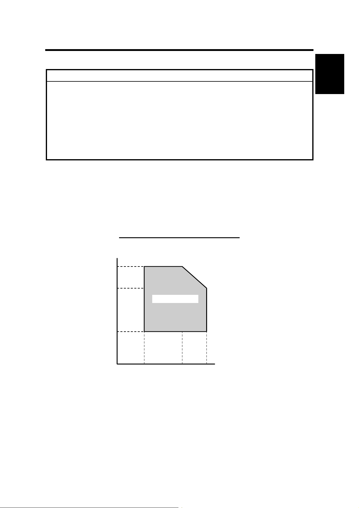
–Temperature and Humidity Chart–
Humidity
80%
54%
Operation range
15%
10°C
(50°F)
27°C
(80.6°F)
32°C
(89.6°F)
Temperature
B121I920.WMF
1-1

INSTALLATION REQUIREMENTS 1 December, 2003
1. Temperature Range:
10°C to 32°C (50°F to 89.6°F)
2. Humidity Range: 15% to 80% RH
3. Ambient
Less than 1,500 lux (do not expose to direct sunlight)
Illumination:
4. Ventilation: 3 times/hr/person or more
5. Ambient Dust: Less than 0.075 mg/m
3
(2.0 x 10⁻⁶ oz/yd3)
6. Avoid areas exposed to sudden temperature changes:
1) Areas directly exposed to cool air from an air conditioner.
2) Areas directly exposed to heat from a heater.
7. Do not place the machine where it is exposed to corrosive gases.
8. Do not install the machine at any location over 2,000 m (6,500 ft.) above sea
level.
9. Place the copier on a strong and level base. (Inclination on any side should be
no more than 5 mm.)
10. Do not place the machine where it is subjected to strong vibrations.
1.1.2 MACHINE LEVEL
Front to back: Within 5 mm (0.2") of level
Right to left: Within 5 mm (0.2") of level
1-2
1 December, 2003 INSTALLATION REQUIREMENTS
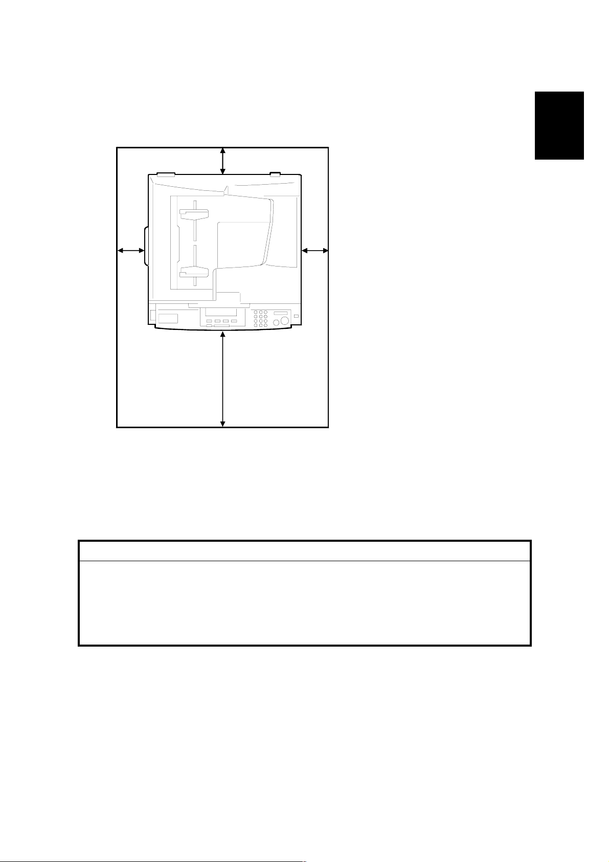
1.1.3 MINIMUM SPACE REQUIREMENTS
Place the copier near the power source, providing clearance as shown:
[C]
Installation
[D][B]
A (front): 750 mm (30")
B (left): 150 mm (6")
C (rear): 50 mm (2")
D (right): 250 mm (10")
[A]
B121I901.WMF
NOTE: The recommended 750 mm front space is sufficient to allow the paper tray
to be pulled out. Additional front space is required to allow operators to
stand at the front of the machine.
1.1.4 POWER REQUIREMENTS
!CAUTION
1. Make sure that the wall outlet is near the machine and easily accessible.
After completing installation, make sure the plug fits firmly into the
outlet.
2. Avoid multi-wiring.
3. Be sure to ground the machine.
1. Input voltage:
North and South America, Taiwan: 110 – 120 V, 60 Hz, 12 A
Europe, Asia: 220 – 240 V, 50/60 Hz, 7 A
1-3
COPIER INSTALLATION 1 December, 2003
1.2 COPIER INSTALLATION
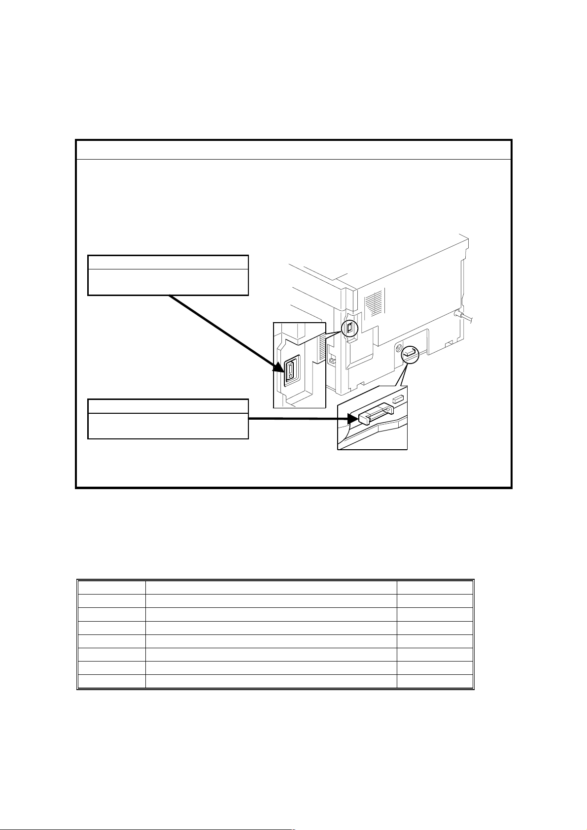
1.2.1 POWER SOCKETS FOR PERIPHERALS
!CAUTION
Rated voltage for peripherals
Make sure to plug the cables into the correct sockets.
ADF/ARDF
Rated voltage output connector
for accessory Max. DC24 V
Paper Tray Unit
Rated voltage output connector
for accessory Max. DC24 V
B121I905.WMF
1.2.2 ACCESSORY CHECK
Check that you have the accessories indicated below.
No. Description Q’ty
1 Operation Instructions–General Settings (-17, -29) 1
2 Operation Instructions–Copy Reference (-17, -29) 1
3 NECR–English (-17) 1
4 NECR–Multi Language (-27, -29) 1
5 Model Nameplate (-22, -29) 1
6 Model Name Decal (-22) 1
7 EU Safety Sheet (-22, -24, -26, -27) 1
1-4
1 December, 2003 COPIER INSTALLATION
1.2.3 INSTALLATION PROCEDURE
!CAUTION
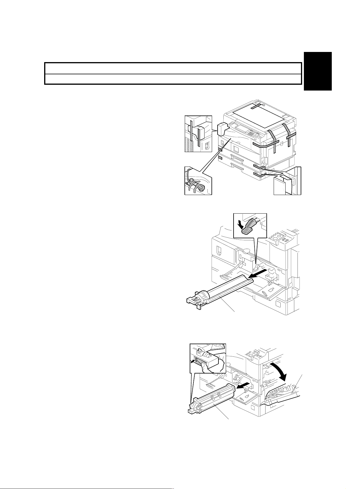
Unplug the machine power cord before starting the following procedure.
1. Remove filament tape and other
padding.
Installation
2. Open the front door and remove the
toner bottle holder [A].
3. Open the right door [B], and remove
the PCU (photoconductor unit) [C].
NOTE: The PCU is locked when the
right door is closed.
[A]
B121I904.WMF
B121I912.WMF
[B]
1-5
[C]
B121I913.WMF
COPIER INSTALLATION 1 December, 2003
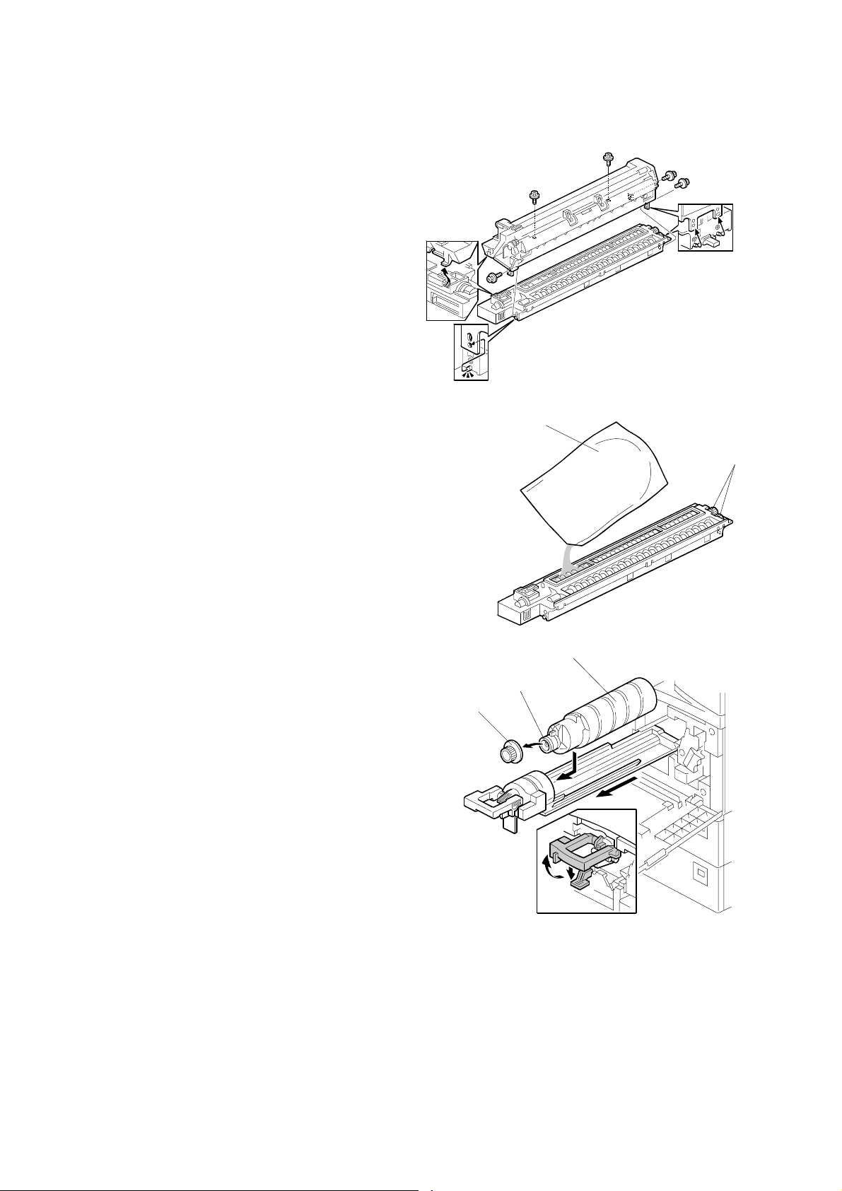
4. Separate the PCU into the upper
part and the lower part (! x 5).
5. Put a sheet of paper on a level
surface and place the upper part on
it.
NOTE: This prevents foreign
material from getting on the
sleeve rollers.
6. Distribute a pack of developer [A] to all
openings equally.
NOTE: 1) Do not spill the developer on
the gears [B]. If you have
spilled it, remove the
developer by using a magnet
or magnetized screwdriver.
2) Do not turn the gear [B] too
much. The developer may
spill.
7. Reassemble the PCU and reinstall it.
8. Shake the toner bottle [C] several times.
NOTE: Do not remove the bottle cap
[D] before you shake the bottle.
9. Remove the bottle cap [D] and install
the bottle on the holder.
NOTE: Do not touch the inner cap [E].
[D]
[E]
[A]
[C]
B121I903.WMF
B121I914.WMF
[B]
10. Set the holder (with the toner bottle) in
the machine.
1-6
B121I915.WMF

1 December, 2003 COPIER INSTALLATION
11. Pull out the paper tray [A] and turn the
paper size dial to the appropriate size.
Adjust the positions of the end and side
guides.
NOTE: To move the side guides,
release the green lock on the
rear side guide.
Installation
[A]
B121I916.WMF
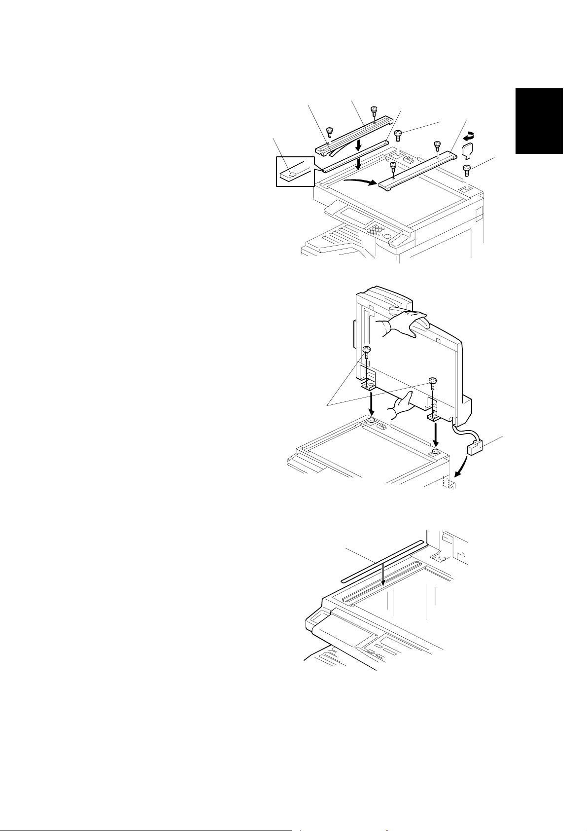
12. Install the optional ARDF, ADF, or platen cover (☛ 1.3/1.4/1.5).
13. Plug in the main power cord and turn on the main switch.
14. Activate the SP mode and execute "Devlpr Initialize" (SP2-214-001).
15. Wait until the message "Completed" is displayed (about 45 seconds).
16. Activate the User Tools and select the menu "Language."
17. Specify a language. This language is used for the operation panel.
18. Load the paper in the paper tray and make a full size copy, and check if the
side-to-side and leading edge registrations are correct. If they are not, adjust
the registrations (☛ 3.13).
1-7
PLATEN COVER INSTALLATION 1 December, 2003
1.3 PLATEN COVER INSTALLATION
1.3.1 ACCESSORY CHECK
Check that you have the accessories indicated below.
No. Description Q’ty
1 Stepped Screw 2
1.3.2 INSTALLATION PROCEDURE
!CAUTION
Unplug the machine power cord before starting the following procedure.
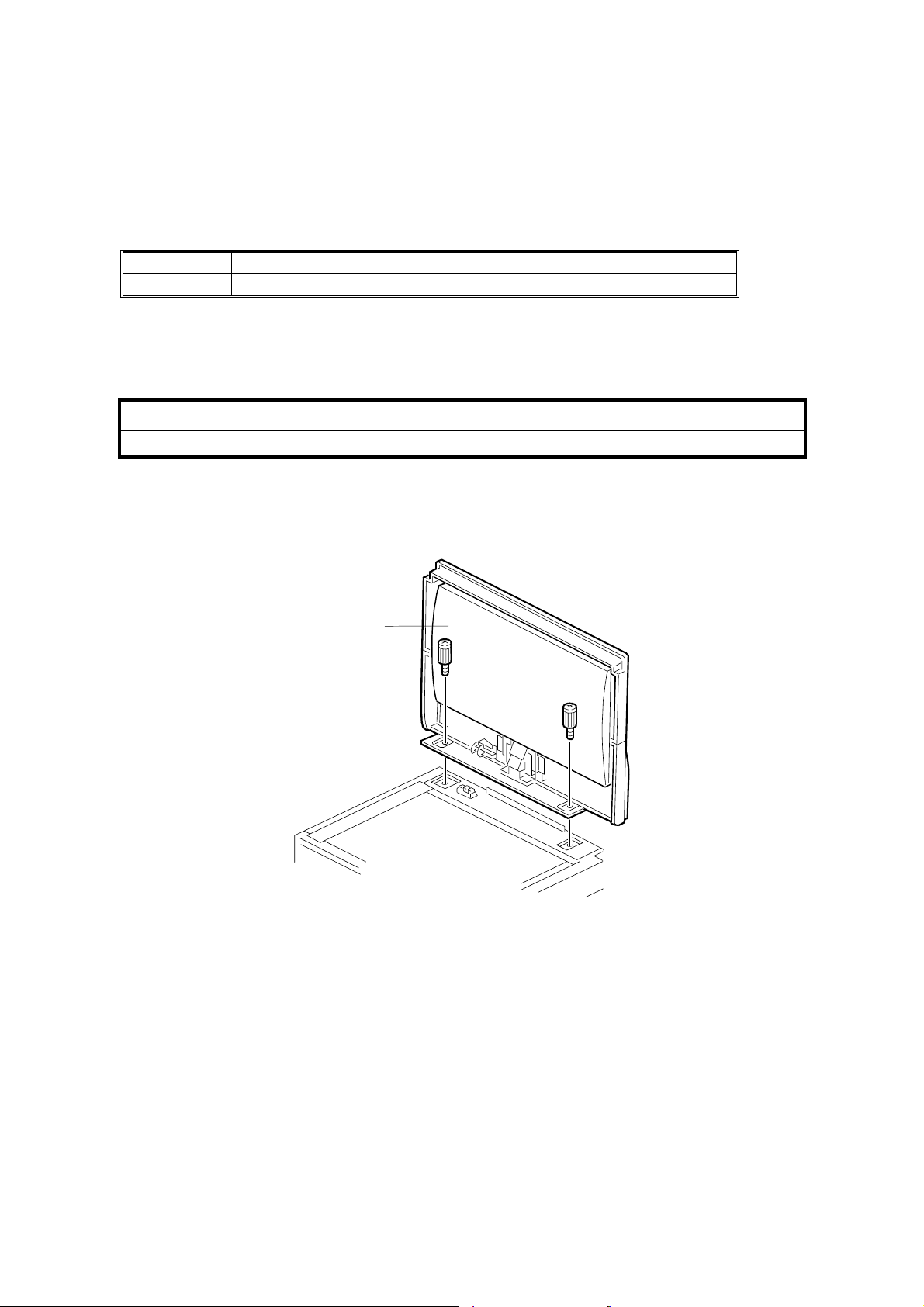
1. Install the platen cover [A] (! x 2).
[A]
B121I910.WMF
1-8
1 December, 2003 ARDF INSTALLATION
1.4 ARDF INSTALLATION
1.4.1 ACCESSORY CHECK
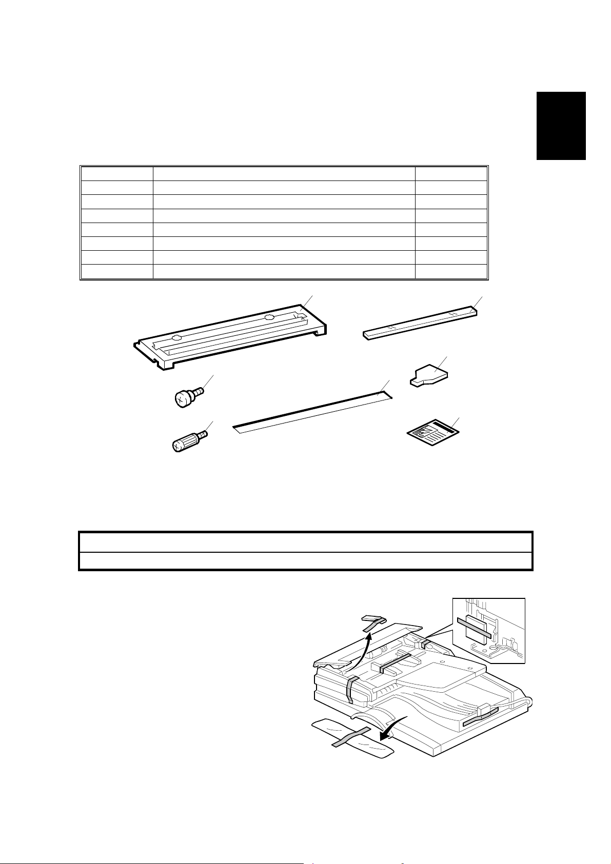
Check the quantity and condition of the accessories against the following list.
No. Description Q’ty
1 Scale Guide 1
2 DF Exposure Glass 1
3 Stud Screw 2
4 Knob Screw 2
5 Original Size Decal 2
6 Screwdriver Tool 1
7 Attention Decal—Top Cover 1
1
2
6
3
4
5
7
Installation
B379I901.WMF
1.4.2 INSTALLATION PROCEDURE
!CAUTION
Unplug the copier power cord before starting the following procedure.
1. Remove the strips of tape.
B379I101.WMF
1-9
ARDF INSTALLATION 1 December, 2003
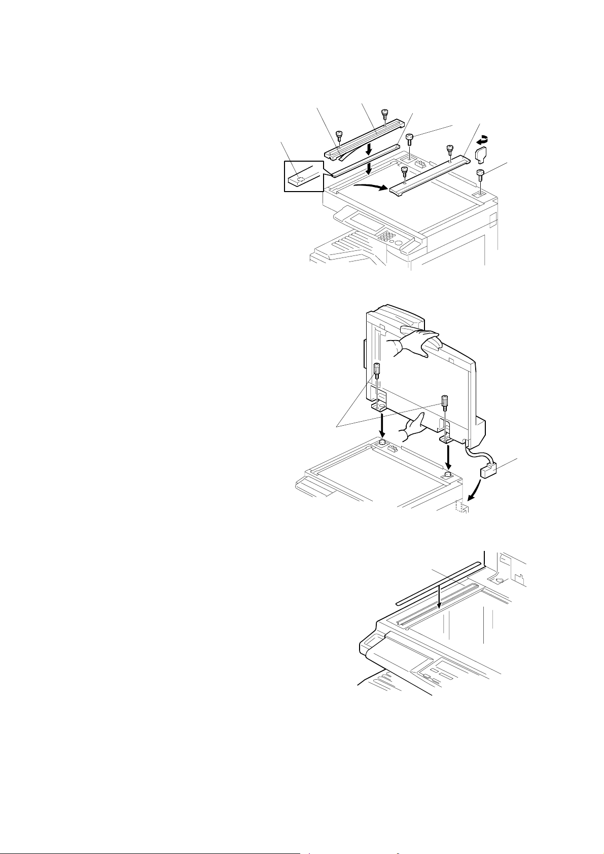
2. Remove the left scale [A]
(! x 2).
3. Place the DF exposure glass
[B] on the glass holder. Make
sure that the white mark [C] is
on the bottom at the front end.
4. Peel off the backing [D] of the
double-sided tape attached to
the rear side of the scale guide
[E], then install the scale guide
(! x 2 [removed in step 2]).
5. Install the two stud screws [F].
6. Mount the ARDF on the copier,
then slide it to the front.
7. Secure the ARDF unit with the
knob screws [G].
[C]
[D]
[E]
[B]
[A]
[F]
B379I902.WMF
[F]
8. Connect the cable [H] to the
copier.
[G]
9. Attach the appropriate original size decal [I]
as shown.
[H]
B379I104.WMFWMF
[I]
1-10
B379I501.WMF

1 December, 2003 ARDF INSTALLATION
[A]
10. Attach an attention decal [A] to the
top cover.
NOTE: The attention decals in the
package are written in
different languages.
11. Turn the main power switch on.
12. Check that the document feeder
works properly.
B379I502.WMF
13. Make a full size copy, and check that the side-to-side and leading edge
registrations are correct. If they are not, adjust the side-to-side and leading
edge registrations. (☛ 3.13.3)
Installation
1-11

ADF INSTALLATION 1 December, 2003
1.5 ADF INSTALLATION
1.5.1 ACCESSORY CHECK
Check the quantity and condition of the accessories against the following list.
No. Description Q’ty
1 Scale Guide 1
2 DF Exposure Glass 1
3 Stud Screw 2
4 Fixing Screw 2
5 Original Size Decal 2
6 Screwdriver Tool 1
7 Attention Decal—Top Cover
1
2
6
3
4
5
7
B387I901.WMF
1.5.2 INSTALLATION PROCEDURE
!CAUTION
Unplug the machine power cord before starting the following procedure.
1. Remove the strips of tape.
1-12
B387I151.WMF
1 December, 2003 ADF INSTALLATION
2. Remove the left scale [A]
(! x 2).
3. Place the DF exposure glass
[B] on the glass holder. Make
sure that the white mark [C] is
on the bottom at the front end.
4. Peel off the backing [D] of the
double-sided tape attached to
the rear side of the scale guide
[E], then install the scale guide
(! x 2 [removed in step 2]).
5. Install the two stud screws [F].
6. Mount the ADF on the copier,
then slide it to the front.
7. Secure the ADF unit with the
fixing screws [G].
[C]
[D]
[E]
[B]
[A]
[F]
B387I902.WMF
Installation
[F]
8. Connect the cable [H] to the
copier.
9. Attach the appropriate scale
decal [I] as shown.
[G]
[H]
B387I104.WMFWMF
[I]
B387I501.WMF
1-13

ADF INSTALLATION 1 December, 2003
[A]
10. Attach an attention decal [A] to the
top cover.
NOTE: The attention decals in the
package are written in
different languages.
11. Turn the main power switch on. Then
check if the document feeder works
properly.
B387I903.WMF
12. Make a full size copy, and check that the side-to-side and leading edge
registrations are correct. If they are not, adjust the side-to-side and leading
edge registrations. (☛ 3.13.3).
1-14
1 December, 2003 TWO-TRAY PAPER TRAY UNIT INSTALLATION
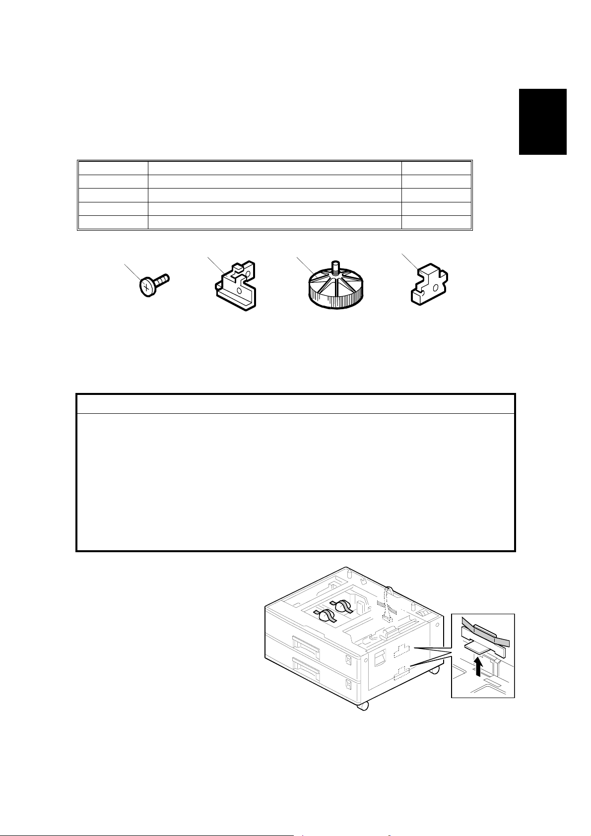
1.6 TWO-TRAY PAPER TRAY UNIT INSTALLATION
1.6.1 ACCESSORY CHECK
Check the quantity and condition of the accessories against the following list.
No. Description Q’ty
1 Screw – M4x10 10
2 Unit Holder 4
3 Adjuster 1
4 Unit Holder 2
4
B384I500.WMF
1
2
3
1.6.2 INSTALLATION PROCEDURE
!CAUTION
1. If the optional fax unit is installed:
• Print out all messages stored in the memory.
• Print out the lists of user-programmed items.
• Print out the system parameter list.
• Disconnect the telephone line.
2. If the optional printer unit is installed:
• Print out all data in the printer buffer.
• Disconnect the network cable.
3. Unplug the machine power cord before starting the following procedure.
Installation
1. Remove the strips of tape.
Make sure that you have
removed all the strips of tape
and all the pieces of cardboard.
B384I158.WMF
1-15

TWO-TRAY PAPER TRAY UNIT INSTALLATION 1 December, 2003
2. Attach the adjuster [A] to the base plate as
shown.
NOTE: If a cabinet is installed, this step is
unnecessary.
3. Remove the cover [B] (1 rivet).
CAUTION: Before placing the copier on
the paper tray unit, make sure
that the harness [C] is safe.
The paper tray unit does not
function properly if the harness
is damaged.
[A]
[B]
B384I001.WMF
B384I901.WMF
4. Set the copier on the paper tray unit.
1-16
[C]
B384I117.WMF
1 December, 2003 TWO-TRAY PAPER TRAY UNIT INSTALLATION
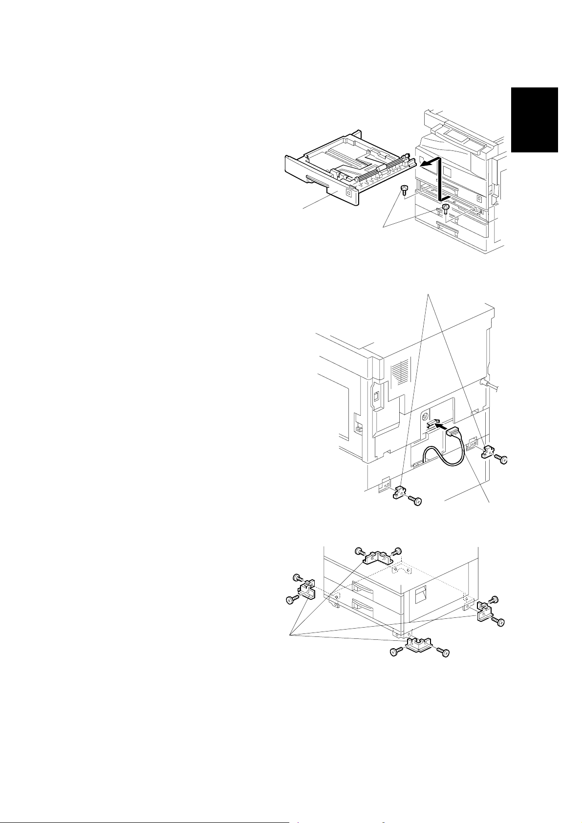
5. One-tray copier model (B121):
Remove the 1st tray cassette [A].
Two-tray copier models
(B122/B123):
Remove the 2nd tray cassette
[A].
Installation
6. Install the two screws [B].
7. Reinstall the tray cassette.
8. Install the two brackets [C]
(1 screw each).
9. Connect the connecting harness
[D] to the copier.
NOTE: There are cutouts in the
plug on both sides. The
left side has one cutout,
and the right side has
two.
10. Reinstall the cover removed in
step 3 (1 rivet).
[A]
[B]
[C]
B384I106.WMF
11. Install the four brackets [E]
(2 screws each).
NOTE: If a cabinet is installed,
this step is unnecessary.
[E]
1-17
[D]
B384I902.WMF
B384I007.WMF
 Loading...