

Ricoh af180 Service Manual
STINGER-C1
(Machine Code: A250)
SERVICE MANUAL
Subject to change
Ricoh Technical Service
May 17th, 1999

I
IMPORTANT SAFETY NOTICES
PREVENTION OF PHYSICAL INJURY
1. Before disassembling or assembling parts of the copier and peripherals,
make sure that the copier power cord is unplugged.
2. The wall outlet should be near the copier and easily accessible.
3. Note that some components of the copier and the paper tray unit are
supplied with electrical voltage even if the main power switch is turned off.
4. If any adjustment or operation check has to be made with exterior covers off
or open while the main switch is turned on, keep hands away from electrified
or mechanically driven components.
5. If the “Start” key is pressed before the copier completes the warm-up period
(the “Start” key starts blinking red and green alternatively), keep hands away
from the mechanical and the electrical components as the copier starts
making copies as soon as the warm-up period is completed.
6. The inside and the metal parts of the fusing unit become extremely hot while
the copier is operating. Be careful to avoid touching those components with
your bare hands.
HEALTH SAFETY CONDITIONS
1. Always replace the ozone filters with the specified ones at the specified
intervals.
2. Toner is non-toxic, but if you get it in your eyes by accident, it may cause
temporary eye discomfort. Try to remove with eye drops or flush with water
as first aid. If unsuccessful, get medical attention.
OBSERVANCE OF ELECTRICAL SAFETY STANDARDS
1. The copier and its peripherals must be installed and maintained by a
customer service representative who has completed the training course on
those models.
2. The danger of explosion exists if batteries on the FCU and JBIG are
incorrectly replaced. Replace only with the same or an equivalent type
recommended by the manufacturer. Discard used batteries in accordance
with the manufacturer’s instructions.

SAFETY AND ECOLOGICAL NOTES FOR DISPOSAL
1. Do not incinerate AIO cartridge. Toner dust may ignite suddenly when
exposed to and open flame.
2. Dispose of used AIO cartridge in accordance with local regulations. (This is
non-toxic supplies.)
3. Dispose of replaced parts in accordance with local regulations.
4. When keeping used lithium batteries in or der to dispos e of them later, do not
put more than 100 batteries per sealed box. Storing larger numbers or not
sealing them apart may lead to chemical reactions and heat build-up.
LASER SAFETY
The Center for Devices and Radiological Health (CDRH) prohibits the repair of
laser-based optical units in the field. The optical housing unit can only be repaired
in a factory or at a location with the requisite equipment. The laser subsystem is
replaceable in the field by a qualified Customer Engineer. The laser chassis is not
repairable in the field. Customer engineers are therefore directed to return all
chassis and laser subsystems to the factory or service depot when replacement of
the optical subsystem is required.
WARNING
I
Use of controls, or adjustment, or performance of procedures other than
those specified in this manual may result in hazardous radiation exposure.
WARNING FOR LASER UNIT
I
WARNING: Turn off the main switch before attempting any of the
procedures in the Laser Unit section. Laser beams can
seriously damage your eyes.
CAUTION MARKING:

TABLE OF CONTENTS
1. OVERALL MACHINE INFORMAT ION........................................1-1
1.1 SPECIFICATIONS.................................................................................... 1-1
1.2 MACHINE CONFIGURATION.................................................................. 1-5
1.3 PAPER PATH........................................................................................... 1-6
1.4 MECHANICAL COMPONENT LAYOUT................................................... 1-7
1.5 ELECTRICAL COMPONENT DESCRIPTIONS........................................ 1-8
1.5.1 COPIER ENGINE ............................................................................ 1-8
1.6 DRIVE LAYOUT ..................................................................................... 1-11
1.7 COPY PROCESS................................................................................... 1-12
1.7.1 OVERVIEW ................................................................................... 1-12
1.8 BOARD STRUCTURE............................................................................ 1-14
1.8.1 OVERVIEW ................................................................................... 1-14
1.8.2 DESCRIPTION .............................................................................. 1-15
2. DETAILED SECTION DESCRIPTIONS.......................................2-1
2.1 SCANNING............................................................................................... 2-1
2.1.1 OVERVIEW ..................................................................................... 2-1
2.1.2 SCANNER DRIVE ........................................................................... 2-2
2.1.3 ORIGINAL SIZE DETECTION IN PLATEN MODE.......................... 2-3
2.2 IMAGE PROCESSING .............................................................................2-5
2.2.1 OVERVIEW ..................................................................................... 2-5
2.2.2 SBU (SENSOR BOARD UNIT)........................................................ 2-7
2.2.3 AUTO IMAGE DENSITY (ADS)....................................................... 2-8
2.2.4 IMAGE PROCESSING UNIT (IPU).................................................. 2-9
2.2.5 MEMORY CONTROLLER AND EXTENDED MEMORY
BOARD (EMB)............................................................................... 2-20
2.2.6 VIDEO CONTROL UNIT (VCU)..................................................... 2-21
2.2.7 IMAGE PROCESSING SUMMARY............................................... 2-23
2.3 LASER EXPOSURE............................................................................... 2-33
2.3.1 OVERVIEW ................................................................................... 2-33
2.3.2 OPTICAL PATH............................................................................. 2-34
2.3.3 AUTO POWER CONTROL (APC) ................................................. 2-35
2.3.4 LD SAFETY SWITCH.................................................................... 2-36
2.4 ALL-IN-ONE CARTRIDGE (AIO CARTRIDGE)...................................... 2-37
2.4.1 OVERVIEW ................................................................................... 2-37
2.4.2 DRIVE............................................................................................ 2-38
2.4.3 DRUM CHARGE............................................................................ 2-39
2.4.4 DEVELOPMENT............................................................................ 2-40
2.4.5 DRUM CLEANING......................................................................... 2-43
2.5 IMAGE TRANSFER AND PAPER SEPARATION.................................. 2-44
2.5.1 OVERVIEW ................................................................................... 2-44
2.5.2 TRANSFER CURRENT SETTINGS.............................................. 2-45
2.5.3 TRANSFER ROLLER CLEANING................................................. 2-46
2.6 PAPER FEED.........................................................................................2-47
i

2.6.1 OVERVIEW ................................................................................... 2-47
2.6.2 BUILT-IN TRAY............................................................................. 2-48
2.6.3 BY-PASS TRAY............................................................................. 2-51
2.6.4 PAPER REGISTRATION............................................................... 2-53
2.6.5 MISFEED DETECTION................................................................. 2-54
2.7 IMAGE FUSING...................................................................................... 2-57
2.7.1 OVERVIEW ................................................................................... 2-57
2.7.2 FUSING UNIT DRIVE.................................................................... 2-58
2.7.3 PRESSURE ROLLER/PAPER EXIT.............................................. 2-59
2.7.4 FUSING UNIT DRIVE RELEASE................................................... 2-59
2.7.5 FUSING TEMPERATURE CONTROL........................................... 2-60
2.7.6 OVERHEAT PROTECTION........................................................... 2-63
2.7.7 ENERGY SAVER MODE............................................................... 2-63
3. INSTALLA T ION...........................................................................3-1
3.1 INSTALLATION REQUIREMENTS .......................................................... 3-1
3.1.1 ENVIRONMENT ..............................................................................3-1
3.1.2 MACHINE LEVEL............................................................................ 3-2
3.1.3 MINIMUM SPACE REQUIREMENTS.............................................. 3-3
3.1.4 POWER REQUIREMENTS.............................................................. 3-4
3.2 COPIER INSTALLATION.......................................................................... 3-5
3.2.1 ACCESSORY CHECK..................................................................... 3-5
3.2.2 COPIER INSTALLATION PROCEDURE......................................... 3-6
3.3 ADF INSTALLATION.............................................................................. 3-10
3.3.1 ACCESSORY CHECK................................................................... 3-10
3.3.2 ADF INSTALLATION PROCEDURE ............................................. 3-11
3.4 PAPER TRAY UNIT (1 TRAY) INSTALLATION ..................................... 3-14
3.4.1 ACCESSORY CHECK................................................................... 3-14
3.4.2 PAPER TRAY UNIT INSTALLATION PROCEDURE..................... 3-15
3.5 PAPER TRAY UNIT (2 TRAYS) INSTALLATION................................... 3-18
3.5.1 ACCESSORY CHECK................................................................... 3-18
3.5.2 PAPER TRAY UNIT INSTALLATION PROCEDURE..................... 3-19
3.6 1-BIN SORTER INSTALLATION............................................................ 3-23
3.6.1 ACCESSORY CHECK................................................................... 3-23
3.6.2 1-BIN SORTER INSTALLATION PROCEDURE............................ 3-24
3.7 PLATEN COVER INSTALLATION.......................................................... 3-29
3.7.1 ACCESSORY CHECK................................................................... 3-29
3.7.2 PLATEN COVER INSTALLATION PROCEDURE......................... 3-29
3.8 EXTENDED MEMORY BOARD INSTALLATION................................... 3-30
3.8.1 ACCESSORY CHECK................................................................... 3-30
3.8.2 EXTENDED MEMORY BOARD INSTALLATION
PROCEDURE................................................................................ 3-31
3.9 DRUM HEATER INSTALLATION (OPTION).......................................... 3-32
3.10 OPTICS ANTI-CONDENSATION HEATER INSTALLATION
(OPTION).............................................................................................. 3-33
3.11 TRAY HEATER INSTALLATION.......................................................... 3-34
ii

4. SERVICE TABLES......................................................................4-1
4.1 GENERAL CAUTION................................................................................ 4-1
4.1.1 AIO CARTRIDGE (ALL-IN-ONE CARTRIDGE)............................... 4-1
4.1.2 TRANSFER ROLLER UNIT............................................................. 4-1
4.1.3 SCANNER UNIT..............................................................................4-1
4.1.4 LASER UNIT.................................................................................... 4-2
4.1.5 FUSING UNIT.................................................................................. 4-2
4.1.6 PAPER FEED.................................................................................. 4-2
4.1.7 OTHERS.......................................................................................... 4-2
4.2 SERVICE PROGRAM MODE................................................................... 4-3
4.2.1 SERVICE PROGRAM MODE OPERATION.................................... 4-3
4.1.2 SERVICE PROGRAM MODE TABLES........................................... 4-4
4.1.3 TEST PATTERN PRINTING (SP5-902)......................................... 4-38
4.1.4 INPUT CHECK (SP5-803)............................................................. 4-39
4.1.5 OUTPUT CHECK (SP5-804)......................................................... 4-44
4.1.6 COPY JAM HISTORY DISPLAY (SP7-903) .................................. 4-46
4.1.7 ORIGINAL JAM HISTORY DISPLAY (SP7-905)........................... 4-47
4.1.8 SYSTEM PARAMETER AND DATA LISTS (SP5-992).................. 4-48
4.1.9 MEMORY ALL CLEAR (SP5-801)................................................. 4-49
4.1.10 PROGRAM UPLOAD/DOWNLOAD............................................. 4-50
4.1.11 NVRAM DATA DOWNLOAD....................................................... 4-53
4.1.12 APS AND PLATEN/DF COVER SENSOR OUTPUT DISPLAY
(SP4-301) .................................................................................... 4-55
4.1.13 DF APS SENSOR OUTPUT DISPLAY (SP6-901)....................... 4-56
4.1.14 DISPLAY LANGUAGE (SP5-808)................................................ 4-57
4.1.15 SERIAL NUMBER INPUT (SP5-811)........................................... 4-57
4.3 USER TOOLS......................................................................................... 4-58
4.1.1 HOW TO ENTER AND EXIT USER TOOLS..................................4-58
4.1.2 USER TOOLS TABLE ................................................................... 4-58
4.4 LEDS...................................................................................................... 4-60
4.5 SPECIAL TOOLS AND LUBRICANTS ................................................... 4-60
4.5.1 SPECIAL TOOLS........................................................................... 4-60
4.5.2 LUBRICANTS................................................................................ 4-60
5. PREVENTIVE MAINTENANCE SCHEDULE...............................5-1
5.1 PM TABLE................................................................................................ 5-1
5.2 HOW TO CLEAR THE MAINTENANCE COUNTER................................ 5-2
6. REPLACEMENT AND ADJUSTMENT ........................................ 6-1
6.1 EXTERIOR REMOVAL............................................................................. 6-1
6.1.1 REAR COVER................................................................................. 6-1
6.1.2 COPY TRAY.................................................................................... 6-1
6.1.3 LEFT COVER.................................................................................. 6-1
6.1.4 FRONT COVER............................................................................... 6-2
6.1.5 UPPER RIGHT COVER................................................................... 6-3
6.1.6 LOWER RIGHT COVER.................................................................. 6-3
6.1.7 RIGHT SMALL COVER................................................................... 6-3
6.1.8 OPERATION PANEL....................................................................... 6-4
iii

6.2 SCANNER................................................................................................ 6-5
6.2.1 EXPOSURE GLASS REMOVAL...................................................... 6-5
6.2.2 LENS BLOCK REMOVAL................................................................ 6-7
6.2.3 EXPOSURE LAMP REPLACEMENT.............................................. 6-8
6.2.4 1ST SCANNER ALIGNMENT ADJUSTMENT................................. 6-9
6.2.5 2ND SCANNER POSITION ADJUSTMENT.................................. 6-10
6.3 LASER UNIT........................................................................................... 6-11
6.3.1 CAUTION DECAL LOCATIONS.................................................... 6-11
6.3.2 LASER UNIT/TONER SHIELD GLASS REMOVAL....................... 6-12
6.3.3 LD UNIT/LASER SYNCHRONIZATION DETECTOR
REMOVAL ..................................................................................... 6-13
6.3.4 EXIT TRAY PAPER SENSOR REMOVAL..................................... 6-13
6.3.5 POLYGONAL MIRROR MOTOR REMOVAL................................. 6-14
6.3.6 LASER UNIT ALIGNMENT ADJUSTMENT................................... 6-15
6.4 IMAGE TRANSFER................................................................................ 6-16
6.4.1 TRANSFER ROLLER REMOVAL.................................................. 6-16
6.5 FUSING.................................................................................................. 6-17
6.5.1 FUSING UNIT REMOVAL ............................................................. 6-17
6.5.2 HOT ROLLER, FUSING LAMP AND THERMOFUSE
REPLACEMENT............................................................................ 6-18
6.5.3 PRESSURE ROLLER REPLACEMENT........................................ 6-20
6.5.4 FUSING THERMISTOR REPLACEMENT..................................... 6-21
6.5.5 HOT ROLLER STRIPPER PAWL REPLACEMENT...................... 6-22
6.6 PAPER FEED.........................................................................................6-23
6.6.1 PAPER FEED ROLLER REPLACEMENT..................................... 6-23
6.6.2 FRICTION PAD REPLACEMENT.................................................. 6-24
6.6.3 STANDARD TRAY PAPER FEED CLUTCH REPLACEMENT...... 6-25
6.6.4 VERTICAL TRANSPORT ROLLER/SENSOR/
CLUTCH REPLACEMENT ............................................................ 6-26
6.6.5 BY-PASS FEED ROLLER REPLACEMENT.................................. 6-27
6.6.6 BY-PASS FEED FRICTION PAD REPLACEMENT....................... 6-28
6.6.7 BY-PASS FEED SENSOR REPLACEMENT................................. 6-29
6.6.8 BY-PASS TRAY REMOVAL ..........................................................6-30
6.6.9 BY-PASS FEED PAPER WIDTH SENSOR REMOVAL ................ 6-31
6.6.10 REGISTRATION ROLLER REMOVAL........................................ 6-32
6.6.11 REGISTRATION SENSOR REPLACEMENT.............................. 6-33
6.6.12 TONER END SENSOR REPLACEMENT.................................... 6-34
6.7 OTHERS................................................................................................. 6-35
6.7.1 MAIN MOTOR/GEAR BOX REPLACEMENT................................ 6-35
6.7.2 IOB (INPUT OUTPUT BOARD) REPLACEMENT ......................... 6-36
6.7.3 BICU (BASE-ENGINE IMAGE CONTROL UNIT)
REPLACEMENT............................................................................ 6-37
6.7.4 POWER SUPPLY UNIT AND B/C/T POWER PACK
REPLACEMENT............................................................................ 6-38
6.8 STANDARD WHITE DENSITY ADJUSTMENT...................................... 6-39
6.9 COPY ADJUSTMENT PRINTING/SCANNING....................................... 6-40
6.9.1 PRINTING...................................................................................... 6-40
6.9.2 SCANNING.................................................................................... 6-42
6.9.3 ADF IMAGE ADJUSTMENT.......................................................... 6-44
iv

7. TROUBLESHOOTING.................................................................7-1
7.1 SERVICE CALL CONDITIONS................................................................. 7-1
7.1.1 SUMMARY....................................................................................... 7-1
7.1.2 SC CODE DESCRIPTIONS............................................................. 7-2
7.2 BLOWN FUSE TABLE............................................................................ 7-10
7.3 ELECTRICAL COMPONENT DEFECTS................................................ 7-10
7.3.1 SWITCHES.................................................................................... 7-10
7.3.2 SENSORS..................................................................................... 7-11
OPTIONS
DOCUMENT FEEDER (A859)
1. OVERALL INFORMATION.................................................... A859-1
1.1 SPECIFICATIONS..............................................................................A859-1
1.2 MECHANICAL COMPONENT LAYOUT.............................................A859-2
1.3 ELECTRICAL COMPONENT LAYOUT..............................................A859-3
1.4 ELECTRICAL COMPONENT DESCRIPTION....................................A859-4
1.5 DRIVE LAYOUT .................................................................................A859-5
2. DETAILED SECTION DESCRIPTIONS.................................A859-6
2.1 ORIGINAL SIZE DETECTION............................................................A859-6
1.2 PICK-UP AND SEPARATION.............................................................A859-8
1.3 ORIGINAL TRANSPORT AND EXIT MECHANISM ...........................A859-9
1.4 STAMP .............................................................................................A859-10
1.5 TIMING CHARTS .............................................................................A859-11
1.5.1 A4 SIDEWAYS.........................................................................A859-11
1.5.2 A4 SIDEWAYS, STAMP MODE...............................................A859-12
1.6 JAM DETECTION.............................................................................A859-13
1.7 OVERALL ELECTRICAL CIRCUIT...................................................A859-14
3. REPLACEMENT AND ADJUSTMENT................................A859-15
3.1 FEED UNIT REMOVAL....................................................................A859-15
3.2 SEPARATION ROLLER REPLACEMENT........................................A859-15
3.3 PICK-UP ROLLER REPLACEMENT................................................ A859-16
3.4 FEED BELT REPLACEMENT..........................................................A859-16
3.5 ORIGINAL SET SENSOR REPLACEMENT.....................................A859-17
3.6 ORIGINAL WIDTH/LENGTH/TRAILING EDGE SENSOR
REPLACEMENT...............................................................................A859-18
3.7 ORIGINAL EXIT TRAY/FRONT COVER/REAR COVER
REMOVAL........................................................................................A859-19
3.8 FEED COVER OPEN SENSOR/DF OPEN SENSOR
REPLACEMENT...............................................................................A859-19
3.9 FEED CLUTCH/PICK-UP SOL/TRANSPORT MOTOR
REPLACEMENT...............................................................................A859-20
3.10 DF FEED COVER REMOVAL........................................................A859-21
3.11 REGISTRATION SENSOR REPLACEMENT.................................A859-21
3.12 STAMP SOLENOID REPLACEMENT............................................A859-22
v

PAPER TRAY UNIT (A860)
1. OVERALL MACHINE INFORMAT ION..................................A860-1
1.1 SPECIFICATIONS..............................................................................A860-1
1.2 MECHANICAL COMPONENT LAYOUT.............................................A860-2
1.3 ELECTRICAL COMPONENT LAYOUT..............................................A860-3
1.4 ELECTRICAL COMPONENT DESCRIPTION....................................A860-4
1.5 DRIVE LAYOUT .................................................................................A860-5
2. DETAILED DESCRIPTIONS .................................................A860-6
2.1 PAPER FEED AND SEPARATION MECHANISM..............................A860-6
2.2 PAPER LIFT MECHANISM................................................................A860-7
2.3 PAPER END DETECTION.................................................................A860-9
2.4 PAPER HEIGHT DETECTION.........................................................A860-10
1.5 PAPER SIZE DETECTION...............................................................A860-12
1.6 SIDE AND END FENCES.................................................................A860-13
3. REPLACEMENT AND ADJUSTMENT................................A860-14
3.1 FEED ROLLER REPLACEMENT.....................................................A860-14
3.2 TRAY MAIN BOARD REPLACEMENT.............................................A860-15
3.3 TRAY MOTOR REPLACEMENT......................................................A860-15
3.4 RELAY CLUTCH REPLACEMENT...................................................A860-16
3.5 UPPER PAPER FEED CLUTCH REPLACEMENT ..........................A860-17
3.6 LOWER PAPER FEED CLUTCH REPLACEMENT..........................A860-18
3.7 LIFT MOTOR REPLACEMENT........................................................A860-19
3.8 PAPER END SENSOR REPLACEMENT.........................................A860-20
3.9 VERTICAL TRANSPORT SENSOR REPLACEMENT ..................... A860-20
3.10 PAPER SIZE SWITCH REPLACEMENT........................................A860-21
PAPER TRAY UNIT (A861)
1. OVERALL MACHINE INFORMAT ION..................................A861-1
1.1 SPECIFICATIONS..............................................................................A861-1
1.2 MECHANICAL COMPONENT LAYOUT.............................................A861-2
1.3 ELECTRICAL COMPONENT LAYOUT..............................................A861-3
1.4 ELECTRICAL COMPONENT DESCRIPTION....................................A861-4
1.5 DRIVE LAYOUT .................................................................................A861-5
2. DETAILED DESCRIPTIONS .................................................A861-6
2.1 PAPER FEED AND SEPARATION ....................................................A861-6
2.2 PAPER LIFT MECHANISM................................................................A861-7
2.3 PAPER END DETECTION .................................................................A861-9
2.4 PAPER HEIGHT DETECTION.........................................................A861-10
2.5 PAPER SIZE DETECTION...............................................................A861-12
2.6 SIDE AND END FENCES.................................................................A861-13
vi

3. REPLACEMENT AND ADJUSTMENT................................A861-14
3.1 FEED ROLLER REPLACEMENT.....................................................A861-14
3.2 TRAY MAIN BOARD REPLACEMENT.............................................A861-15
3.3 TRAY MOTOR REPLACEMENT......................................................A861-15
3.4 TRAY MOTOR REPLACEMENT......................................................A861-16
3.5 LIFT MOTOR REPLACEMENT........................................................A861-17
3.6 PAPER END SENSOR REPLACEMENT.........................................A861-18
3.7 PAPER SIZE SWITCH REPLACEMENT..........................................A861-18
1-BIN SORTER (A869)
1. OVERALL INFORMATION.................................................... A869-1
1.1 SPECIFICATIONS..............................................................................A869-1
1.2 MECHANICAL COMPONENT LAYOUT.............................................A869-2
1.3 ELECTRICAL COMPONENT LAYOUT..............................................A869-3
1.4 ELECTRICAL COMPONENT DESCRIPTION....................................A869-4
2. DETAILED SECTION DESCRIPTIONS.................................A869-5
2.1 BASIC OPERATION...........................................................................A869-5
3. REPLACEMENT AND ADJUSTMENT..................................A869-6
3.1.1 TOP COVER REMOVAL...........................................................A869-6
3.1.2 TRAY OPEN SWITCH REPLACEMENT...................................A869-6
3.1.3 PAPER SENSOR AND EXIT SENSOR REPLACEMENT.........A869-6
vii

17 May, 1999 SPECIFICATIONS
1. OVERALL MACHINE INFORMATION
1.1 SPECIFICATIONS
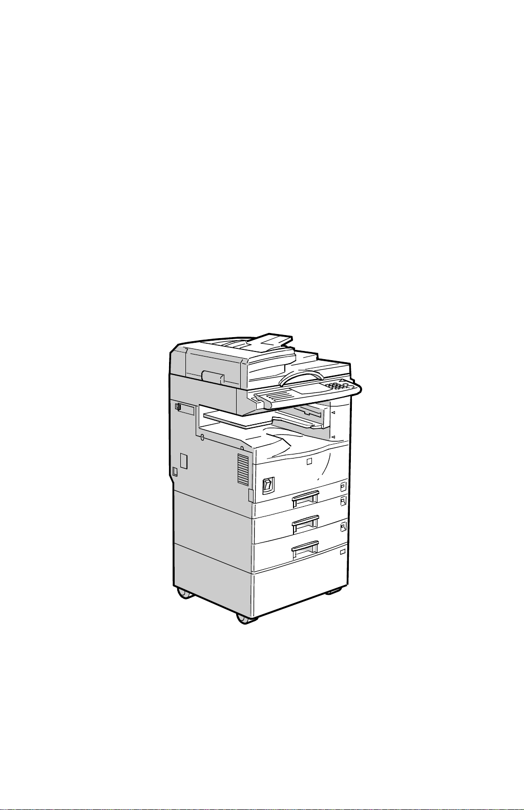
Configuration: Desktop
Copy Process: Dry electrostatic transfer system
Originals: Sheet/Book
Original Size: Maximum A3/11" x 17"
Copy Paper Size: Maximum
A3/11" x 17"
Minimum
A5/8
B6 lengthwise/5
Custom sizes in the by-pass tray:
Width: 90 ~ 305 mm (3.5" ~ 12.0")
Length: 148 ~ 1,260 mm (5.8" ~ 49.6")
Copy Paper Weight: Paper Tray:
60 ~ 90 g/m2, 16 ~ 24 lb
By-pass:
60 ~ 162 g/m2, 16 ~ 43 lb
Reproduction Ratios: 3 Enlargement and 3 Reduction
1/2
" x 5
" sideways (Paper tray)
1/2
1/2
" x 8
" (By-pass)
1/2
Overall
Information
A4/A3 Version LT/DLT Version
200%
Enlargement
Full Size 100% 100%
Reduction
141%
122%
93%
71%
50%
Zoom: 50% to 200% in 1% steps
Power Source: 120 V, 60 Hz:
More than 10 A (for North America)
220 ~ 240 V, 50/60 Hz
More than 6 A (for Europe/Asia)
110 V, 50/60 Hz
More than 11 A (for Taiwan)
155%
129%
121%
93%
78%
65%
1-1

SPECIFICATIONS 17 May, 1999
Power Consumption:
Mainframe Only Full System
120 V 220 ~ 240 V 120 V 220 ~ 240 V
Maximum Less than
1.1 kW
Copying Approx.
450 W
Warm-up
Stand-by Approx.
Energy Saver Level 1 Approx. 60 W Approx. 60 W Approx. 60 W Approx. 60 W
Energy Saver Level 2 Approx. 30 W Approx. 30 W Approx. 30 W Approx. 30 W
Auto Shut off 0 W 0 W 0 W 0 W
Approx.
860 W
110 W
Less than
1.1 kW
Approx.
450 W
Approx.
760 W
Approx.
110 W
Less than
1.2 kW
Approx.
460 W
Approx.
870 W
Approx.
130 W
Less than
1.3 kW
Approx.
460 W
Approx.
770 W
Approx.
130 W
NOTE:
1) Full system: Mainframe + ADF + 1-bin Sorter + Paper Tray Unit
2) Without the optional heaters, fax unit, and pri nter contr ol ler
Noise Emission (Sound Power Level):
Stand-by (Mainframe only): US/Asia Model: 42 dB(A)
Europe Model: 30 dB(A)
Operating (Mainframe only): US/Asia Model: 60 dB(A)
Europe Model: 66 dB(A)
Operating (Full System): 66 dB(A)
Off Mode: 30 dB(A)
NOTE:
1) The above measurements were made in accordance with ISO 7779.
2) Full System: Mainframe + ADF + 1-bin Sorter + Paper Tray Unit
Dimensions (W x D x H): 550 x 575 x 460 mm (21.7" x 22.7" x 18.2")
NOTE:
Measurement Conditions
1) With by-pass feed table closed
2) Without the ADF
Weight: Less than 35 kg (78 lb)
Not including ADF, Platen Cover, and AIO
1-2

17 May, 1999 SPECIFICATIONS
Copying Speed in Multicopy mode (copies/minute):
A4 sideways/
11" x 8
Non-memory copy mode 15 10 11
Memory copy mode 18 10 12
NOTE:
Measurement Conditions
1/2
"
A3/11" x 17" B4/8
" x 14"
1/2
1) Not APS mode
2) A4/LT copying
3) Full size
Warm-up Time: Less than 30 seconds (20°C, 68°F): 115 V machine
Less than 40 seconds (20°C, 68°F): 230 V machine
First Copy Time: Less than 6.5 seconds
NOTE:
Measurement Conditions
1) When polygonal mirror motor is spinning.
2) Not APS mode
3) A4/LT copying
4) Full size
Copy Number Input: Ten-key pad, 1 to 99 (count up or count down)
Manual Image Density: 7 steps
Overall
Information
Automatic Reset: 60 seconds is the standard setting; it can be changed
with a User Tool.
Automatic Shut Off: 15 minutes is the standard setting; it can be changed
with a User Tool.
Copy Paper Capacity: Paper Tray:
250 sheets
Optional Paper Tray Unit:
500 sheets x 1, or 500 sheets x 2
By-pass Tray:
100 sheets (A4, B5, A5, B6, 8
1/2
10 sheets (A3, B4, 11" x 17", 8
" x 11", 5
" x 13")
1/2
1/2
" x 8
1/2
")
1 sheets (non-standard sizes)
NOTE:
Copy weight: 80g/m2 (20 lb).
Toner Replenishment: All-in-one toner cassette cartridge (750 g/cartridge)
Toner Yield: 12 k copies (A4 sideways, 6% full black, 1 to 1 copying,
ADS mode)
1-3

SPECIFICATIONS 17 May, 1999
Optional Equipment:
·
Platen cover
·
Auto document feeder
·
Paper tray unit (1 tray)
·
Paper tray unit (2 trays)
·
1-bin sorter
·
Tray heater
·
Optics anti-condensation heater
·
Drum heater
·
Copier feature expander (48 MB memory)
Copy Capacity: Copy Tray: 250 sheets (without 1-bin sorter),
125 sheets (with 1-bin sorter)
1-bin Sorter: 125 sheets
Memory Capacity:
Standard (16 MB) Optional (+48 MB)
Sort, Rotate Sort
Number of pages
A4, 8
B4, 8
A3, 11" x 17"
A4 ITU-T#4 12% 35 sheets 99 sheets
" x 11"
1/2
1/2
" x 14"
❍❍
❍❍
❍❍
A4 6% 80 sheets 99 sheets
NOTE:
The paper sizes that can be used with Rotate Sort are A4/8
and B5 only.
: Available
❍
" x 11"
1/2
1-4
17 May, 1999 MACHINE CONFIGURATION
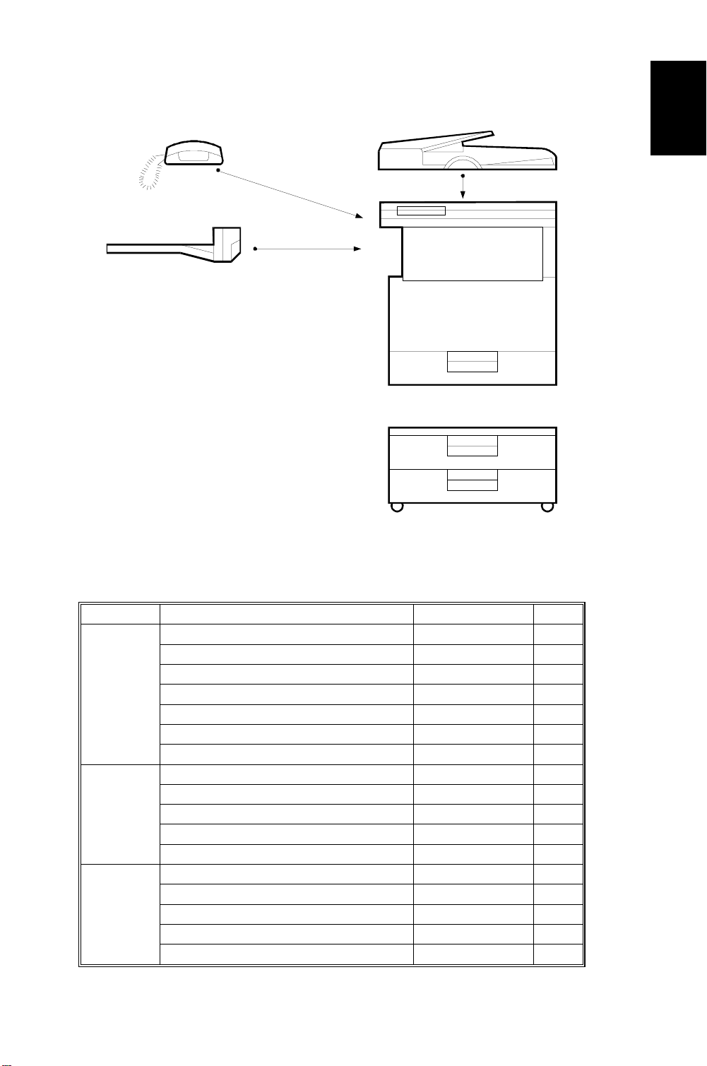
1.2 MACHINE CONFIGURATION
A
B
C
D
Overall
Information
A250V501.WMF
Version Item Machine Code No.
Copier
Fax
Printer
Copier A250 D
ADF (Optional) A859 C
Platen Cover (Optional) A893
Paper Tray Unit - 1 tray (Optional) A861
Paper Tray Unit - 2 trays (Optional) A860 E
1-bin Sorter (Optional) A869 B
Memory 48 MB (Optional) A887
Fax Controller (Optional) A891
Telephone (Optional) H160 A
ISDN (Optional) A890
PC Fax Expander (Optional) A894
Fax Function Expander (Optional) A892
Printer Controller (Optional) B305
PS Option (Optional) B308
HDD (Optional) G690
NIB (Optional) B307
Memory 32 or 64 MB (Optional) G688
E
1-5
PAPER PATH 17 May, 1999
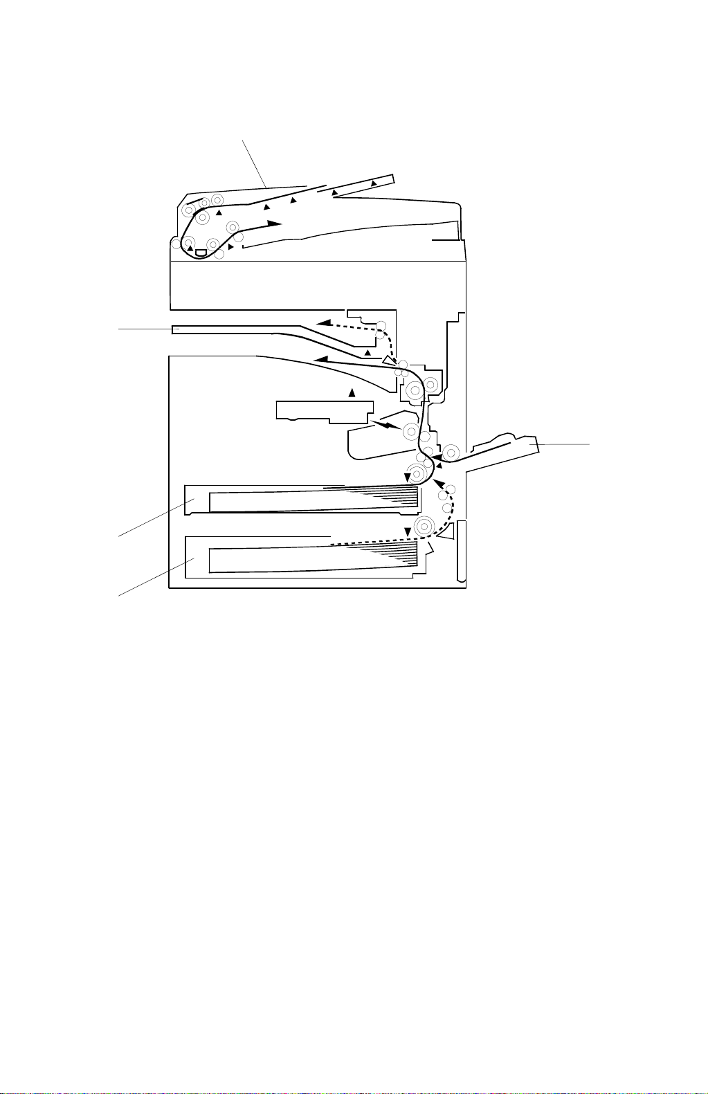
1.3 PAPER PATH
1
5
2
4
3
1. Optional ADF
2. By-pass feed tray
3. Optional paper tray (1 tray)
4. Paper tray
5. Optional 1-bin sorter
A250V000.WMF
1-6
17 May, 1999 MECHANICAL COMPONENT LAYOUT
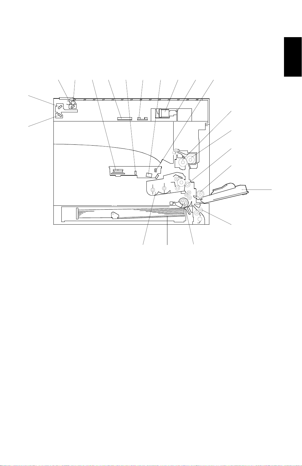
1.4 MECHANICAL COMPONENT LAYOUT
1 2 3 4 5 6 7 8 9 10
21
11
Overall
Information
20
1. 1st mirror (scanner)
2. Exposure lamp
3. Polygonal mirror motor
4. Original width sensor
5. 1st mirror (laser unit)
6. Original length sensor
7. Barrel toroidal lens (BTL)
8. Lens
9. SBU board
10. F-theta mirror
11. Hot roller
12
13
14
15
16
19 18 17
A250V561.WMF
12. Pressure roller
13. Transfer roller
14. By-pass feed roller
15. By-pass table
16. Vertical transport roller
17. Paper feed roller
18. Bottom plate
19. All-in-one cartridge (AIO cartridge)
20. 3rd mirror
21. 2nd mirror
1-7

ELECTRICAL COMPONENT DESCRIPTIONS 17 May, 1999
1.5 ELECTRICAL COMPONENT DESCRIPTIONS
Refer to the electrical component layout on the reverse side of the point-to-point
diagram for the location of the components, using the symbols and index numbers.
1.5.1 COPIER ENGINE
Symbol Name Function Index No.
Motors
M1 Scanner Drives the 1st and 2nd scanners. 4
M2 Polygonal Mirror Turns the polygonal mirror. 28
M3 Main Drives the main unit components. 12
M4 Exhaust Fan Removes heat from around the fusing unit. 46
Magnetic Clutches
MC1 Paper Feed Starts paper feed from the tray. 14
MC2 By-pass Feed Starts paper feed from the by-pass table. 15
MC3 Vertical Transport Drives the vertical transport rollers. 18
MC4 Registration Drives the registration rollers. 13
Switches
Main Provides power to the machine. If this is
SW1
SW2 Right Door Switch 1 Cuts the +5 V LD dc power line. 30
Right Door Switch 2
SW3
Vertical Transport
SW4
SW5 Paper Size Detects paper size. 24
Sensors
S1
S2
S3
S4
S5 Toner Near-End Detects toner near-end. 21
S6
S7
Cover Switch
Scanner HP
Original Width Detects original width. This is one of the
Original Length 1 Detects original length. This is one of the
Original Length 2
Paper End Informs the CPU when the tray runs out of
Paper Near-End Informs the CPU when the paper in the
off, there is no power supplied to the
machine.
Detects if the front door is open or not, and
cuts the +24 V dc power line for the main
motor and power pack.
Detects if the front door is open or not, and
cuts the +24 V dc power line for the vertical
transport clutch.
Informs the CPU when the 1st and 2nd
scanners are at home position.
APS (Auto Paper Select) sensors.
APS (Auto Paper Select) sensors.
Detects original length. This is one of the
APS (Auto Paper Select) sensors.
paper.
tray is almost finished. The printer
controller uses this sensor.
40
31
25
3
37
6
6
23
19
1-8

17 May, 1999 ELECTRICAL COMPONENT DESCRIPTIONS
Symbol Name Function Index No.
S8
By-pass Tray Paper
Informs the CPU that there is paper in the
by-pass feed table.
16
S9 By-pass Paper Size Detects the paper size in the by-pass tray. 20
S10 Vertical Transport Detects misfeeds. 22
S11
Registration
Detects misfeeds and controls registration
clutch off-on timing.
17
S12 Fusing Exit Detects misfeeds. 35
S13
Exit Tray Paper Detects if there is paper on the exit tray or
not.
27
Platen Cover Informs the CPU that the platen cover is in
S14
the up or down position (related to the
5
APS/ARE functions).
S15 AIO Set Informs the CPU that an AIO is installed. 33
PCBs
PCB1
PCB2
PCB3
PCB4
BICU
PSU Provides dc power to the system and ac
IOB Controls the fusing lamp and the
SBU
Controls all base engine functions both
directly and through other control boards.
power to the fusing lamp and heaters.
mechanical parts of the machine.
Contains the CCD, and outputs a video
signal to the BICU board.
44
39
45
8
PCB5 Lamp Stabilizer Stabilizes the power to the exposure lamp. 7
PCB6 LD Unit Cont rols the laser diode. 26
PCB7 Operation Panel Controls the operation panel. 36
PCB8 Memory (Option) Expands memory capacity. —
PCB9
PCB10
PCB11
Printer Controller
(Option)
FCU (Option) Controls all fax communications and fax
NCU (Option) Switches the analog line between the fax
Receives print data from a PC.
features, in cooperation with the BICU.
unit and the external telephone.
42
43
47
Overall
Information
Lamps
L1
Exposure Lamp Applies hig h int ensity light t o the original
for exposure.
L2 Fusing Lamp Heats the hot roller. 10
Heaters
H1
Anti-condensation
(Option)
Turns on when the main switch is off to
prevent moisture from forming on the
optics.
Drum (Option) Turns on when the main switch is off to
H2
prevent moisture from forming around the
drum.
1-9
2
1
—

ELECTRICAL COMPONENT DESCRIPTIONS 17 May, 1999
Symbol Name Function Index No.
Others
TF1
Fusing Thermofuse
Opens the fusing lamp circuit if the fusing
unit overheats.
9
TH1 Fusing Thermistor Detects the temperature of the hot roller. 11
PP1
LSD 1
CO1
CO2
C/B/T Power Pack
Laser Synchronization
Detector
Total Counter Keeps track of the total number of prints
Key Counter (Option)
Provides high voltage for the charge,
development and transfer rollers.
Detects the laser beam at the start of the
main scan.
made.
Used for control of authorized use. If this
feature is enabled for coping, coping will be
38
29
48
—
impossible until it is installed.
LED1 Exit Tray Indicates if there is paper on the exit tray. 32
LED2
1-bin Sorter Indicates if there is paper on the 1-bin
sorter. 1-bin sorter is option.
34
SP1 Speaker T urns on during fax communication. 41
1-10
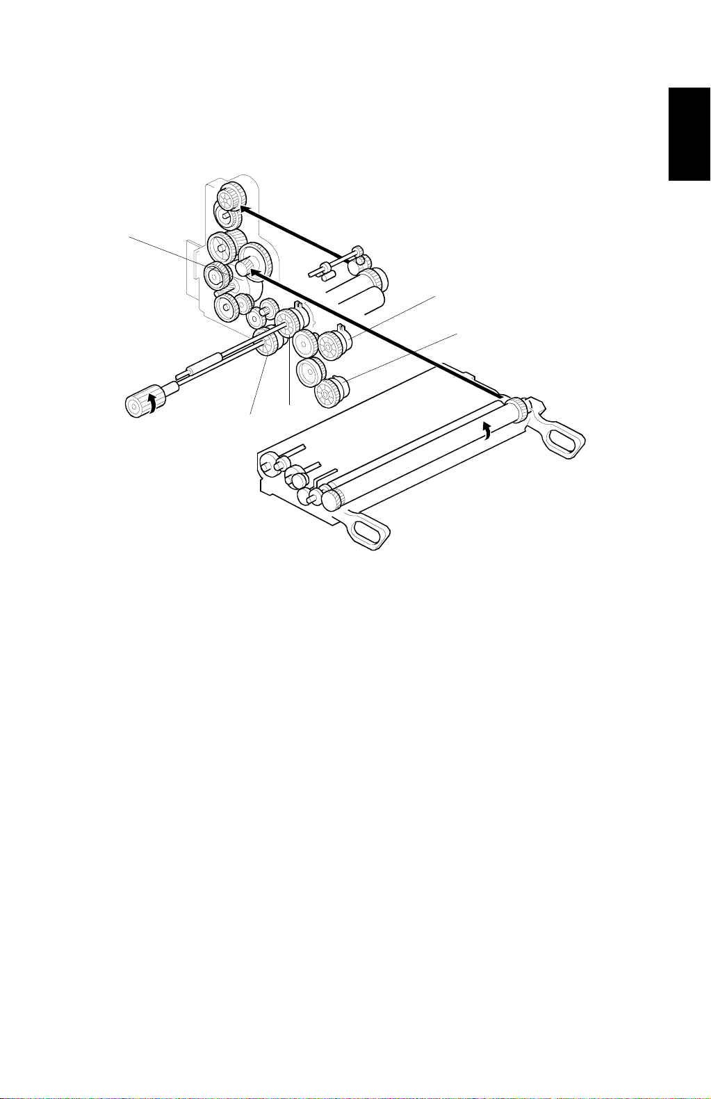
17 May, 1999 DRIVE LAYOUT
1.6 DRIVE LAYOUT
5
1
2
3
4
Overall
Information
1. By-pass feed clutch
2. Vertical transport clutch
3. Registration clutch
4. Paper feed clutch
5. Main motor
A250V109.WMF
1-11
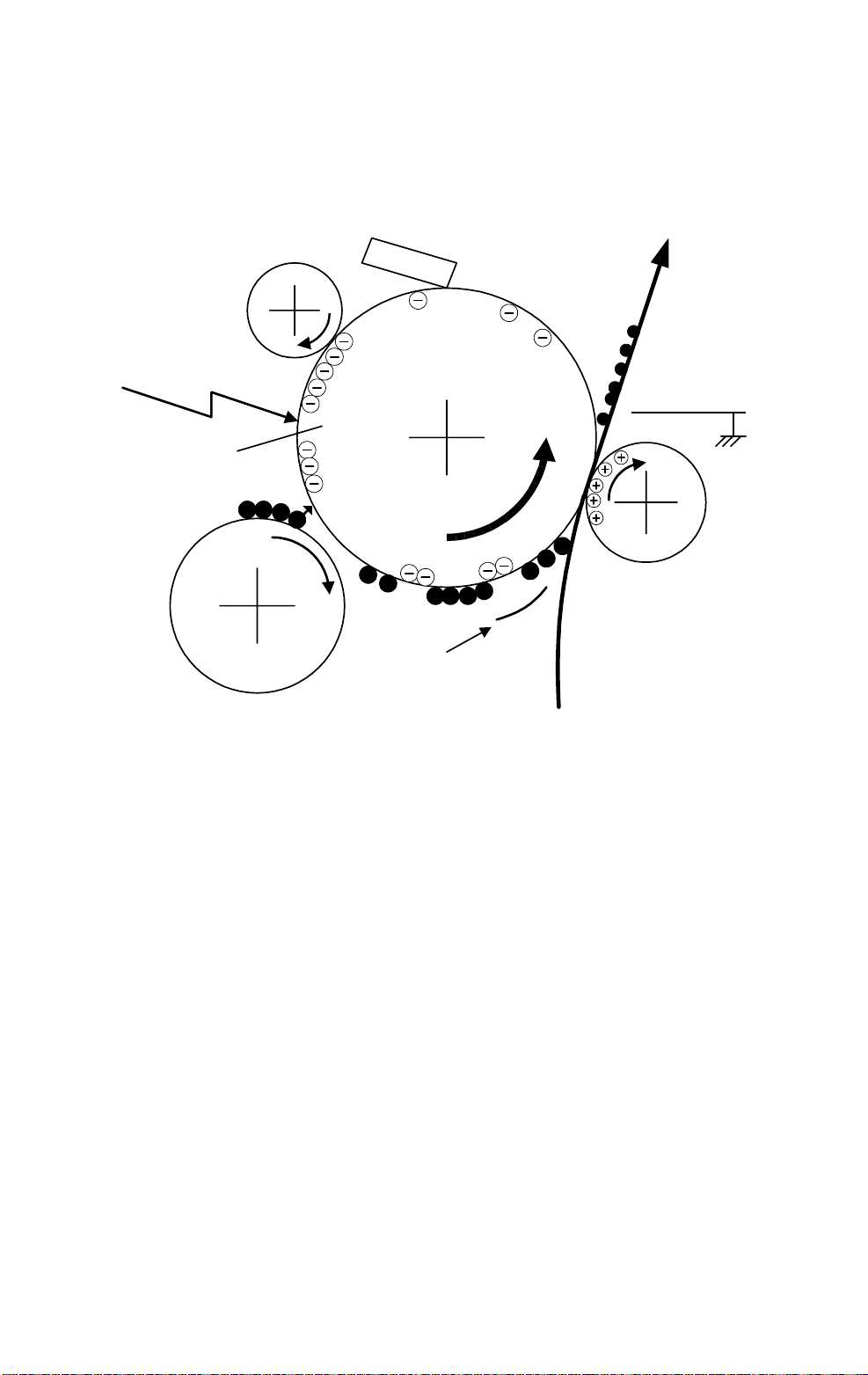
COPY PROCESS 17 May, 1999
1.7 COPY PROCESS
1.7.1 OVERVIEW
6
1
OPC
–600 V
5
2
–100 V
4
3
–400 V
A250V507.WMF
1. DRUM CHARGE
In the dark, the charge roller gives a negative charge of –600 volts to the
organic photo-conductive (OPC) drum. The charge remains on the surface of
the drum because the OPC layer has a high electrical resistance in the dark.
2. LASER EXPOSURE
The processed data scanned from the original is retrieved from the memory
and transferred to the drum by a laser beam, which forms an electrical latent
image on the drum surface. The amount of charge remaining as a latent image
on the drum (about –100 volts) depends on the laser beam intensity, which is
controlled by the BICU board.
3. DEVELOPMENT
The development roller charges the toner with a negative bias of –400 volts.
Toner particles jump across to the drum and electrostatically attach to the
areas of the drum surface where the laser reduced the negative charge on the
drum.
1-12

17 May, 1999 COPY PROCESS
4. IMAGE TRANSFER
Paper is fed to the area between the drum surface and the transfer roller at the
proper time for aligning the copy paper and the developed image on the drum
surface. Then, the transfer roller applies a high positive charge to the reverse
side of the paper. This positive charge pulls the toner particles from the drum
surface onto the paper. At the same time, the paper is electrostatically attracted
to the transfer roller.
5. PAPER SEPARATION
Paper separates from the drum as a result of the electrostatic attraction
between the paper and the transfer roller. The discharge plate helps separate
the paper from the drum.
6. CLEANING
The cleaning blade removes any toner remaining on the drum surface after the
image transfers to the paper.
7. QUENCHING
There is no quenching lamp. The power supply board applies 1.6 kVp-p (1.05
mA) 1 kHz AC to the charge roller. This current removes any remaining voltage
on the drum surface.
Overall
Information
1-13
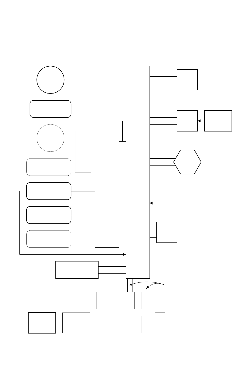
BOARD STRUCTURE 17 May, 1999
1.8 BOARD STRUCTURE
1.8.1 OVERVIEW
Scanner
Motor
Scanner Sensors
DF
Motor
DF Sensors,
Solenoids
Laser Printer
Sensors, Solenoids,
Motors, Clutches
PSU
DF
Drive
PCB
IOB
BICU
Flat Cable
Harness
Harness
Laser Synchronization
Signal = Fibre Optic Cable
SBU
LDD
Circuit
Board
Polygon
Mirror
Motor
Photo
Diode
Peripheral Sensors,
Motors, Solenoids,
Clutches
Operation Panel
Standard Option
EMB
Harness
Flat Cable
Fax Controller Mother Board
Printer Controller
A250V504.WMF
1-14

17 May, 1999 BOARD STRUCTURE
1.8.2 DESCRIPTION
1. BICU (Base Engine and Image Control Unit)
The main board controls the following functions:
·
Engine sequence
·
Scanner, laser printer engine
·
Timing control for peripherals
·
Image processing, video control
·
Operation control
·
Various application boards (fax, printer)
·
Machine control, system control
2. IOB (I/O Board)
The IOB handles the following functions:
·
Drive control for the sensors, motors, and solenoids of the printer and
scanner
·
High voltage control board control
·
Serial interfaces with peripherals
·
Fusing control
3. SBU (Sensor Board Unit)
Overall
Information
The SBU deals with the analog signals from the CCD and converts them into digital
signals.
4. EMB (Extended Memory Board) (Option)
The EMB stores the image data. An extra 48 MB of memory can be added. This
increases the number of pages that can be stored.
1-15
17 May, 1999 SCANNING
2. DETAILED SECTION DESCRIPTIONS
2.1 SCANNING
2.1.1 OVERVIEW
[E] [A] [D] [C]
[G] [F] [B]
Detailed
Descriptions
A250D003.WMF
An exposure lamp [A], a xenon lamp in this model, illuminates the original. The 1st,
2nd, 3rd mirrors, and lens [B] reflect the image onto the CCD (charge coupled
device) [C]. The SBU (Sensor Board Unit) consists of the CCD and the lens.
The 1st scanner [D] consists of the exposure lamp, a reflector [E], and the 1st
mirror [F].
The exposure lamp is energized by a DC supply to avoid uneven light intensity as
the 1st scanner moves in the sub-scan direction. The entire exposure lamp surface
is frosted to ensure even exposure in the main scan direction.
The light reflected by the reflector is of almost equal intensity to the light from the
exposure lamp, to reduce shadows on pasted originals.
An optics anti-condensation heater [G] is available as an option. It can be installed
on the left side of the scanner unit. It turns on whenever the power cord is plugged
in and the machine is in off condition.
2-1

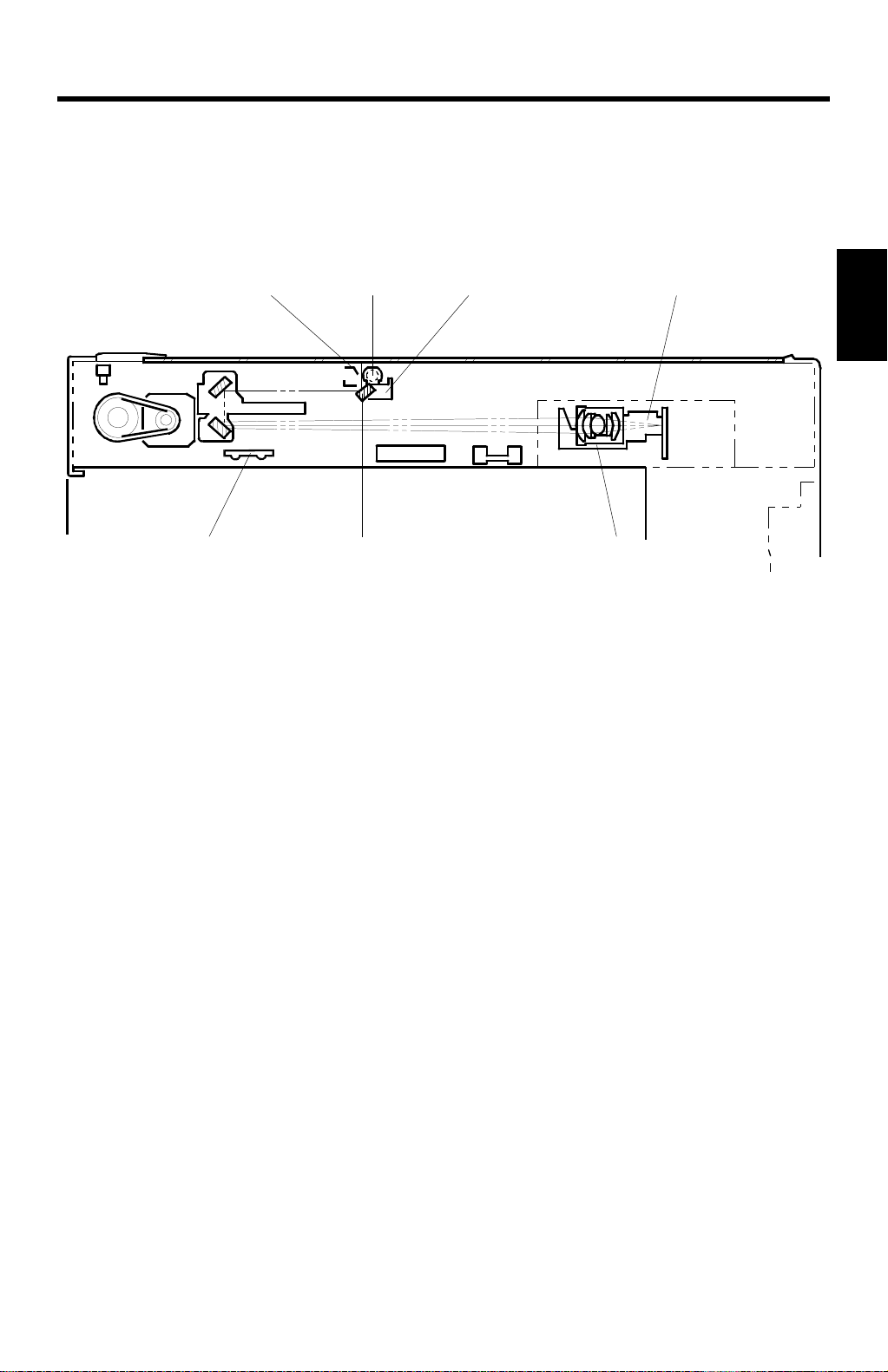
SCANNING 17 May, 1999
2.1.2 SCANNER DRIVE
[A]
[E]
[D]
[C]
[B]
[D]
A250D001.WMF
The scanner drive motor [A] (a stepper motor) drives the 1st and 2nd scanners [B,
C] through the timing belts [D], scanner drive pulley [E], and the Accuride rail at the
rear.
Book Mode
The main CPU controls and operates the scanner drive motor. In full size mode,
the 1st scanner speed is 92 mm/s during scanning. The 2nd scanner speed is half
that of the 1st scanner.
In reduction or enlargement mode, the scanning speed depends on the
magnification ratio (M: 0.5 to 2.00). The returning speed is always the same,
whether in full size or magnification mode.
Changing the scanner drive motor speed changes the magnification in the subscan direction. Use SP mode (SP4-101) to adjust this.
In the main scan direction, magnification is done by image processing on the BICU
(Base Engine Image Control Unit) board. Adjust magnification in the main scan
direction with SP4-008.
ADF Mode
The scanners remain in their home position (the scanner H.P sensor detects the
1st scanner) to scan the original. The ADF motor feeds the original through the
ADF.
In reduction/enlargement mode, changing the ADF motor speed adjusts the image
length in the sub-scan direction (adjust with SP6-007). The BICU board adjusts the
magnification in the main scan direction, in the same way as in book mode (adjust
with SP4-008).
2-2
17 May, 1999 SCANNING
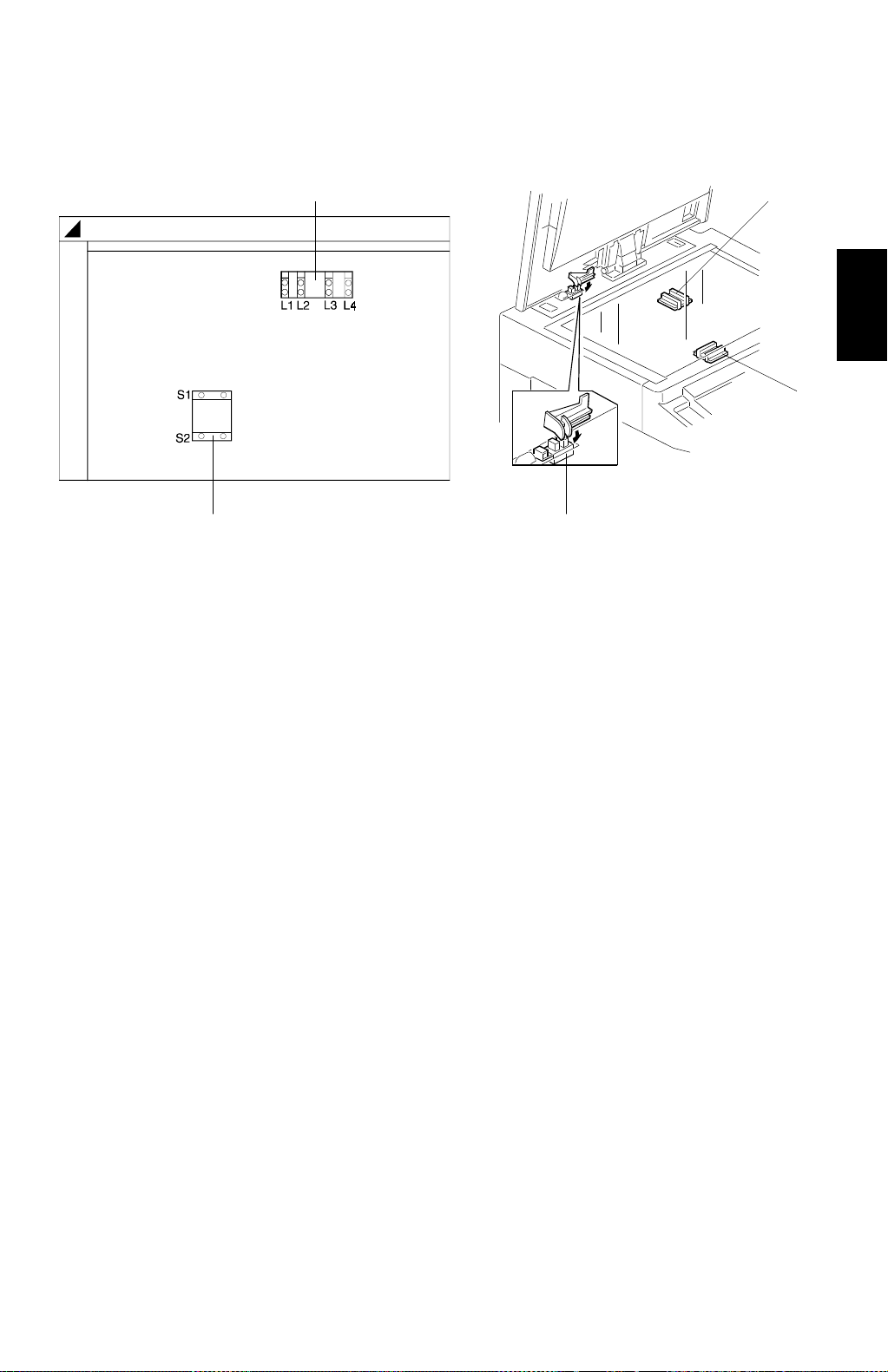
2.1.3 ORIGINAL SIZE DETECTION IN PLATEN MODE
[B]
[B]
[A]
A250D526.WMF
[A]
[C]
A250D002.WMF
In the optics cavity, there are four reflective sensors in the 115 V machines, and six
reflective sensors in the 230 V machines. These are the original width sensors [A]
and the original length sensors [B], and they detect the length and width of the
original. They are also known as the APS (Auto Paper Selection) sensors.
Detailed
Descriptions
While the main switch is on, these sensors are active and the original size data is
always sent to the CPU. However, the CPU checks the data only when the platen
cover is opened.
The main CPU takes the original size data when the platen cover sensor [C]
activates. This is when the platen is about 15 cm above the exposure glass. At this
time, only the sensor(s) located underneath the original receive the reflected light
and switch on. The other sensor(s) remain off. The main CPU can recognize the
original size from the on/off signals from the APS sensors.
If the copy is made with the platen fully open, the main CPU decides the original
size from the sensor outputs when the Start key is pressed.
2-3

SCANNING 17 May, 1999
Original Size Length Sensors Width Sensors
A4/A3 ver sion LT/DLT version L1 L2 L3 L4 S1 S2
A3 11" x 17"
B4 10" x 14"
F4 8
A4-L 8
B5-L —
A4-S 11" x 8
B5-S —
1/2
" x 14" (8" x 13")
1/2
" x 11"
1/2
"
mmmmmm
mmmmm7
mmm7 77
mm7777
m77777
7777mm
7777m7
m
: ON 7: OFF
NOTE:
The length sensors L1 and L2 are used only for 230 V machines.
For other combinations, the operation panel will display “CANNOT DETECT ORIG.
SIZE”.
The above table shows the sensor output for each original size. This original size
detection method eliminates the necessity for pre-scanning and increases the
machine's productivity.
However, if the by-pass feed table is used, note that the machine assumes that the
copy paper is lengthwise. For example, if A4 sideways paper is placed on the bypass tray, the machine assumes it is A3 paper and scans a full A3 area,
disregarding the original size sensors. However, for each page, the data signal to
the laser diode is stopped to match the copy paper length detected by the
registration sensor. This means that copy time for the first page may be slower
(because of the longer time required for scanning), but it will be normal for the rest
of the job.
2-4

17 May, 1999 IMAGE PROCESSING
g
g
g
2.2 IMAGE PROCESSING
2.2.1 OVERVIEW
Circuit
Data from SBU
IPU
Detailed
Descriptions
Auto Shadin
Scanner Gamma
Correction
Magnification
Filterin
ID Gamma
Correction
Application
(Fax or
Printer Unit)
Gradation Processin
Video Data Control
FCI
Printer Gamma
Correction
LD Controller
EMB
LD Unit
VCU
A250D500.WMF
The CCD generates an analog video signal. The SBU (Sensor Board Unit)
converts the analog signal to an 8-bit digital signal, then it sends the digital signal
to the BICU (Base-engine and Image Control Unit) board.
The BICU board is divided into two image processing blocks; the IPU (Image
Processing Unit), and memory.
·
IPU: Auto shading, filtering, magnification, gamma (g) correction, and
gradation processing
Finally, the BICU board sends the video data to the LD unit at the correct time.
LD unit is divided into two blocks, VCU (Video Control Unit) and LD controller.
·
VCU:
FCI (Fine Character Image) – Smoothing, Printer gamma (g)
correction
·
LD controller:
LD print timing control
2-5
 Loading...