

Page 1

MODEL MT
(Machine Code: B064/B065)
SERVICE MANUAL
Subject to change
Ricoh Technical Service
April 26, 2002
Page 2

!
IMPORTANT SAFETY NOTICES
PREVENTION OF PHYSICAL INJURY
1. Before disassembling or assembling parts of the copier and peripherals,
make sure that the copier power cord is unplugged.
2. The wall outlet should be near the copier and easily accessible.
3. Note that some components of the copier and the paper tray unit are
supplied with electrical voltage even if the main power switch is turned off.
4. If any adjustment or operation check has to be made with exterior covers off
or open while the main switch is turned on, keep hands away from electrified
or mechanically driven components.
5. If the Start key is pressed before the copier completes the warm-up period
(the Start key starts blinking red and green alternatively), keep hands away
from the mechanical and the electrical components as the copier starts
making copies as soon as the warm-up period is completed.
6. The inside and the metal parts of the fusing unit become extremely hot while
the copier is operating. Be careful to avoid touching those components with
your bare hands.
HEALTH SAFETY CONDITIONS
1. Never operate the copier without the ozone filters installed.
2. Always replace the ozone filters with the specified ones at the specified
intervals.
3. Toner and developer are non-toxic, but if you get either of them in your eyes
by accident, it may cause temporary eye discomfort. Try to remove with eye
drops or flush with water as first aid. If unsuccessful, get medical attention.
OBSERVANCE OF ELECTRICAL SAFETY STANDARDS
1. The copier and its peripherals must be installed and maintained by a
customer service representative who has completed the training course on
those models.
2. The NVRAM on the system control board has a lithium battery which can
explode if replaced incorrectly. Replace the NVRAM only with an identical
one. The manufacturer recommends replacing the entire NVRAM. Do not
recharge or burn this battery. Used NVRAM must be handled in accordance
with local regulations.
Page 3
SAFETY AND ECOLOGICAL NOTES FOR DISPOSAL
1. Do not incinerate toner bottles or used toner. Toner dust may ignite suddenly
when exposed to an open flame.
2. Dispose of used toner, developer, and organic photoconductors in
accordance with local regulations. (These are non-toxic supplies.)
3. Dispose of replaced parts in accordance with local regulations.
4. When keeping used lithium batteries in or der to dispose of them later, do not
put more than 100 batteries per sealed box. Storing larger numbers or not
sealing them apart may lead to chemical reactions and heat build-up.
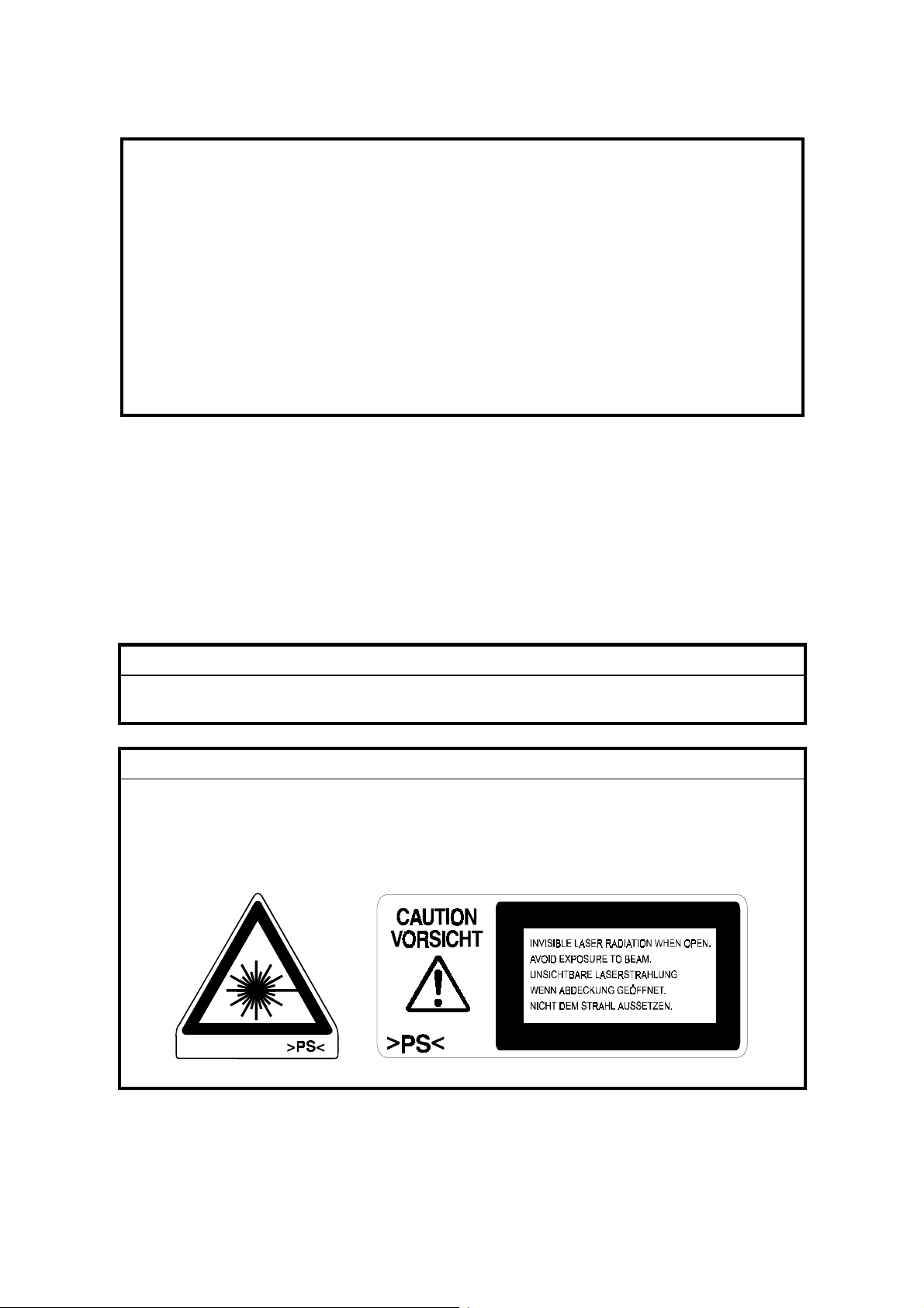
LASER SAFETY
The Center for Devices and Radiological Health (CDRH) prohibits the repair of
laser-based optical units in the field. The optical housing unit can only be repaired
in a factory or at a location with the requisite equipment. The laser subsystem is
replaceable in the field by a qualified Customer Engineer. The laser chassis is not
repairable in the field. Customer engineers are therefore directed to return all
chassis and laser subsystems to the factory or service depot when replacement of
the optical subsystem is required.
!
WARNING
Use of controls, or adjustment, or performance of procedures other than
those specified in this manual may result in hazardous radiation exposure.
!
WARNING
WARNING: Turn off the main switch before atte mpting any of the
procedures in the Laser Unit section. Laser beams can
seriously damage your eyes.
CAUTION MARKING:
Page 4

What This Manual Contains
This preliminary manual describes the installation procedures for the B064/B065
Copier and its peripheral devices:
Main unit
• B064/065 Copier with ADF, Tandem Tray
Peripherals
• B473 LCT. (Attached to the right side of the machine). Provides an additional
feed station of 4,000 sheets.
• B474 LG/B4 Feeder Kit (Attached to B473 LCT). Converts the LCT to a feed
station for legal or B4 size paper.)
• B475 A3/DLT Feeder Kit (Installed in Tandem Tray). Converts the top tray to a
feed station for A3 paper.
• B468/B469 3000-Sheet Finishers (Attached to B064/B065). Both finishers
provide punch, staple, and shift capability. The B468 provides saddle-stitching
with staples, the B469 does not provide saddle-stitching.
• B470 Cover Interposer Tray (Attached to B468/B469). Mounted on top of the
B468/B469 finisher, provides a feed station for inserting cover sheets.
• B471 9-Bin Mailbox (Attached to B468/B469). Mounted on top of the B468/B469
provides 9 output trays, each assigned to a different user.
Conventions in this Manual
This manual uses several symbols.
Symbol What it means
☛
!
"
#
$
%
Refer to section number
See Core Tech Manual for detail s
Screw
Connector
E-ring
Clip ring
Long Edge Feed (LEF)Short Edge Feed (SEF)
Page 5

TABLE OF CONTENTS
1. INSTALLA TION .......................................................................... 1-1
1.1 INSTALLATION REQUIREMENTS...........................................................1-1
1.1.1 OPERATING ENVIRONMENT.........................................................1-1
1.1.2 MACHINE LEVEL.............................................................................1-2
1.1.3 MINIMUM SPACE REQUIREMENTS...............................................1-3
1.1.4 DIMENSIONS...................................................................................1-3
1.1.5 POWER REQUIREMENTS..............................................................1-4
1.2 MAIN MACHINE (B064/B065)...................................................................1-5
1.2.1 ACCESSORY CHECK......................................................................1-5
1.2.2 INSTALLATION PROCEDURE........................................................1-6
Removing Tapes and Retainers ...........................................................1-6
Connecting the ADF..............................................................................1-8
Removing and Filling the Development Unit.........................................1-9
Re-installing the Development Unit.....................................................1-11
Initializing the Drum Settings.............................................................. 1-12
Tandem Tray ......................................................................................1-13
Machine Level.....................................................................................1-15
Date/Time Setting...............................................................................1-15
SP Codes............................................................................................1-15
1.3 A3/DLT FEEDER KIT (B475)...................................................................1-16
1.3.1 ACCESSORY CHECK....................................................................1-16
1.3.2 INSTALLATION PROCEDURE......................................................1-17
1.4 LCT (B473)..............................................................................................1-19
1.4.1 ACCESSORY CHECK....................................................................1-19
1.4.2 INSTALLATION PROCEDURE......................................................1-20
Removing Tape ..................................................................................1-20
Preparing the Main Machine...............................................................1-21
Installing the LCT................................................................................1-21
1.5 LG/B4 FEEDER KIT (B474)....................................................................1-23
1.5.1 ACCESSORY CHECK....................................................................1-23
1.5.2 INSTALLATION PROCEDURE......................................................1-24
1.6 3000-SHEET FINISHERS (B468/B469)..................................................1-27
1.6.1 ACCESSORY CHECK....................................................................1-27
1.6.2 INSTALLATION PROCEDURE......................................................1-28
Removing Tapes and Retainers .........................................................1-28
B468/B469 Installation........................................................................1-29
Selecting the Staple Supply Name ..................................................... 1-31
Enabling Booklet Binding....................................................................1-31
1.7 PUNCH UNIT (B377)...............................................................................1-32
1.7.1 ACCESSORY CHECK....................................................................1-32
1.7.2 INSTALLATION PROCEDURE......................................................1-33
1.8 COVER INTERPOSER TRAY (B470).....................................................1-35
1.8.1 ACCESSORY CHECK....................................................................1-35
1.8.2 INSTALLATION PROCEDURE......................................................1-36
Removing Tapes and Retainers .........................................................1-36
i
Page 6

1.9 9-BIN MAILBOX (B471)...........................................................................1-39
1.9.1 ACCESSORY CHECK....................................................................1-39
1.9.2 INSTALLATION PROCEDURE......................................................1-40
Removing Tapes and Retainers .........................................................1-40
Installation...........................................................................................1-40
1.10 PRINTER/SCANNER KIT (G338), PRINTER KIT (G339).....................1-42
1.10.1 ACCESSORY CHECK..................................................................1-42
1.10.2 INSTALLATION PROCEDURE....................................................1-43
Inserting DIMMs..................................................................................1-43
Installation Procedure.........................................................................1-44
1.11 PS3 (B525-08).......................................................................................1-46
1.11.1 INSTALLATION PROCEDURE....................................................1-46
1.12 USB 2.0 (B525-01)................................................................................1-47
1.12.1 ACCESSORY CHECK..................................................................1-47
1.12.2 INSTALLATION PROCEDURE....................................................1-48
1.12.3 USB SP SETTINGS......................................................................1-49
1.13 IEEE1394 (G561) FIREWIRE INTERFACE ..........................................1-50
1.13.1 ACCESSORY CHECK..................................................................1-50
1.13.2 INSTALLATION PROCEDURE....................................................1-51
1.13.3 UP MODE SETTINGS FOR IEEE 1394 .......................................1-52
1.13.4 SP MODE SETTINGS FOR IEEE 1394........................................1-53
1.14 802.11B WIRELESS LAN (G628)..........................................................1-54
1.14.1 ACCESSORY CHECK..................................................................1-54
1.14.2 INSTALLATION PROCEDURE....................................................1-55
1.14.3 UP MODE SETTINGS FOR WIRELESS LAN..............................1-56
1.14.4 SP MODE SETTINGS FOR 802.11B WIRELESS LAN................1-58
2. PREVENTIVE MAINTENANCE................................................... 2-1
2.1 PM TABLES ..............................................................................................2-1
2.1.1 MAIN MACHINE...............................................................................2-1
2.1.2 ADF ..................................................................................................2-4
2.1.3 OPTIONAL PERIPHERAL DEVICES...............................................2-5
LCT (Large Capacity Tray) B473..........................................................2-5
Cover Interposer Tray B470..................................................................2-5
3000-Sheet Finisher with 50-sheet stapler and Saddle-Stitching
B468B469.............................................................................................2-5
2.2 RELATED SP CODES ..............................................................................2-5
3. REPLACEMENT AND ADJUSTMENT........................................ 3-1
3.1 GENERAL CAUTIONS..............................................................................3-1
3.1.1 DRUM...............................................................................................3-1
3.1.2 DRUM UNIT .....................................................................................3-1
3.1.3 TRANSFER BELT UNIT...................................................................3-2
3.1.4 SCANNER UNIT...............................................................................3-2
3.1.5 LASER UNIT ....................................................................................3-2
3.1.6 CHARGE CORONA..........................................................................3-3
3.1.7 DEVELOPMENT ..............................................................................3-3
3.1.8 CLEANING.......................................................................................3-4
3.1.9 FUSING UNIT...................................................................................3-4
ii
Page 7

3.1.10 PAPER FEED.................................................................................3-4
3.1.11 USED TONER................................................................................3-4
3.2 SPECIAL TOOLS AND LUBRICANTS................................................3-5
3.2.1 SPECIAL TOOLS.............................................................................3-5
3.2.2 LUBRICANTS...................................................................................3-5
3.3 OPERATION PANEL AND EXTERNAL COVERS....................................3-6
3.3.1 OPERATION PANEL........................................................................3-6
3.3.2 FRONT DOOR .................................................................................3-6
3.3.3 RIGHT COVERS..............................................................................3-7
3.3.4 LEFT COVERS.................................................................................3-8
3.3.5 REAR COVERS ...............................................................................3-9
3.4 SCANNER...............................................................................................3-10
3.4.1 ADF AND TOP COVERS ...............................................................3-10
ADF.....................................................................................................3-10
Top Covers.........................................................................................3-11
3.4.2 EXPOSURE GLASS.......................................................................3-12
3.4.3 SCANNER ORIGINAL SIZE SENSORS.........................................3-13
3.4.4 LENS BLOCK.................................................................................3-14
3.4.5 EXPOSURE LAMP.........................................................................3-15
3.4.6 LAMP REGULATOR.......................................................................3-16
3.4.7 SCANNER MOTOR DRIVE BOARD (SDRB).................................3-17
3.4.8 SCANNER MOTOR........................................................................3-18
3.4.9 SCANNER HP SENSOR................................................................3-19
3.4.10 SCANNER WIRE REPLACEMENT..............................................3-20
Preparation for Removal.....................................................................3-20
Wire Removal: Back...........................................................................3-21
Wire Removal: Front...........................................................................3-22
Attaching the New Wire ......................................................................3-23
3.4.11 SCANNER HEATER.....................................................................3-25
3.5 LASER UNIT...........................................................................................3-26
3.5.1 CAUTION DECALS........................................................................3-26
3.5.2 LD UNIT AND POLYGON MOTOR................................................3-27
3.5.3 LASER SYNCHRONIZATION DETECTOR REPLACEMENT........3-29
3.5.4 LASER UNIT ALIGNMENT.............................................................3-30
3.6 DRUM UNIT ............................................................................................3-32
3.6.1 DEVELOPMENT UNIT REMOVAL.................................................3-32
Removal..............................................................................................3-32
Re-installation.....................................................................................3-33
Replacement with a used Development Unit......................................3-33
3.6.2 CHARGE CORONA UNIT..............................................................3-34
3.6.3 CHARGE CORONA WIRE AND GRID...........................................3-35
3.6.4 CHARGE CORONA WIRE CLEANING PADS...............................3-36
3.6.5 OPC DRUM REMOVAL..................................................................3-37
3.6.6 QUENCHING LAMP.......................................................................3-38
3.6.7 DRUM POTENTIAL SENSOR........................................................3-38
3.6.8 CLEANING FILTER........................................................................3-39
3.6.9 CLEANING BLADE.........................................................................3-39
3.6.10 CLEANING BRUSH......................................................................3-40
3.6.11 PICK-OFF PAWLS.......................................................................3-41
iii
Page 8

3.6.12 ID SENSOR..................................................................................3-41
3.6.13 DRUM MOTOR.............................................................................3-42
3.6.14 TONER COLLECTION BOTTLE..................................................3-43
3.6.15 TONER SEPARATION UNIT........................................................3-43
3.6.16 OZONE FILTERS.........................................................................3-44
3.6.17 OPTICS DUST FILTER................................................................3-44
3.6.18 INTERNAL DUST FILTER ............................................................3-44
3.7 DEVELOPMENT UNIT............................................................................3-45
3.7.1 DEVELOPER REPLACEMENT......................................................3-45
3.7.2 DEVELOPMENT FILTER............................................................... 3-47
3.7.3 ENTRANCE SEAL AND SIDE SEALS ...........................................3-48
3.7.4 TD SENSOR...................................................................................3-49
3.7.5 TONER END SENSOR ..................................................................3-49
3.7.6 TONER SUPPLY MOTOR..............................................................3-50
3.7.7 DEVELOPMENT MOTOR..............................................................3-51
3.8 TRANSFER BELT UNIT..........................................................................3-52
3.8.1 TRANSFER BELT UNIT.................................................................3-52
3.8.2 TRANSFER BELT ..........................................................................3-53
3.8.3 TRANSFER ROLLER CLEANING BLADE.....................................3-55
3.8.4 DISCHARGE PLATE......................................................................3-56
3.8.5 TRANSFER POWER PACK...........................................................3-57
3.9 FUSING UNIT..........................................................................................3-58
3.9.1 FUSING UNIT.................................................................................3-58
3.9.2 FUSING UNIT THERMISTORS AND THERMOSTATS.................3-59
3.9.3 WEB CLEANING ROLLER.............................................................3-60
Web Unit Disassembly........................................................................3-60
Web Unit Assembly.............................................................................3-61
3.9.4 WEB MOTOR AND WEB END SENSOR.......................................3-62
3.9.5 PRESSURE ROLLER CLEANING UNIT........................................3-63
3.9.6 FUSING LAMPS, HOT ROLLER, AND PRESSURE ROLLER.......3-64
Important Notes about Fusing Unit Assembly.....................................3-67
3.9.7 PRESSURE ROLLER.....................................................................3-68
3.9.8 STRIPPER PAWLS........................................................................3-69
3.9.9 NIP BAND WIDTH ADJUSTMENT.................................................3-70
3.9.10 FUSING UNIT EXIT SENSOR......................................................3-71
3.9.11 FUSING/EXIT MOTOR.................................................................3-72
3.9.12 FUSING EXIT AND EXIT UNIT ENTRANCE SENSORS.............3-73
3.10 DUPLEX UNIT.......................................................................................3-74
3.10.1 DUPLEX UNIT REMOVAL ...........................................................3-74
3.10.2 DUPLEX UNIT SIDE-TO-SIDE ADJUSTMENT............................3-75
3.10.3 JOGGER FENCE ADJUSTMENT................................................3-75
3.10.4 DUPLEX MOTORS.......................................................................3-76
Duplex Inverter Motor.........................................................................3-76
Duplex Jogger and Transport Motors..................................................3-77
3.10.5 DUPLEX TRANSPORT CLUTCH/JOGGER HP SENSOR...........3-78
3.10.6 DUPLEX ENTRANCE SENSOR ..................................................3-79
3.10.7 DUPLEX TRANSPORT SENSOR 3.............................................3-80
3.10.8 INVERTER EXIT SENSOR, TRANSPORT SENSORS 1 & 2.......3-81
3.10.9 DUPLEX JOGGER BELT ADJUSTMENT.................................... 3-82
iv
Page 9

3.11 PAPER FEED........................................................................................3-83
3.11.1 PAPER TRAY REMOVAL............................................................3-83
Tandem Tray Removal.......................................................................3-83
3.11.2 REAR FENCE RETURN SENSOR REPLACEMENT...................3-85
3.11.3 REAR FENCE HP SENSOR REPLACEMENT.............................3-86
3.11.4 TANDEM RIGHT TRAY PAPER SENSOR REPLACEMENT.......3-87
3.11.5 BOTTOM PLATE LIFT WIRE REPLACEMENT ...........................3-88
3.11.6 TANDEM LCT PAPER SIZE CHANGE........................................3-90
3.11.7 PICK-UP, FEED, SEPARATION ROLLER REPLACEMENT .......3-93
3.11.8 FEED UNIT...................................................................................3-94
3.11.9 SEPARATION ROLLER PRESSURE ADJUSTMENT..................3-96
3.11.10 RELAY SENSOR........................................................................3-97
3.11.11 BY-PASS PAPER SIZE DETECTION BOARD...........................3-98
3.11.12 BY-PASS TRAY ROLLERS........................................................3-99
3.11.13 BY-PASS SEPARATION ROLLER PRESSURE
ADJUSTMENT .........................................................................3-100
3.11.14 REGISTRATION SENSOR.......................................................3-101
3.11.15 REGISTRATION AND BY-PASS UNIT REMOVAL..................3-102
3.12 PCBS AND HDD .................................................................................3-104
3.12.1 BCU BOARD (BASE ENGINE CONTROL UNIT).......................3-104
3.12.2 CONTROLLER BOARD .............................................................3-105
3.12.3 IPU BOARD (IMAGE PROCESSING UNIT)...............................3-106
3.12.4 DEVELOPMENT POWER PACK ...............................................3-106
3.12.5 PSU, PFC BOARDS...................................................................3-107
3.12.6 HDD ............................................................................................3-107
3.12.7 NVRAM.......................................................................................3-108
3.13 ADF.....................................................................................................3-109
3.13.1 ADF COVERS............................................................................3-109
3.13.2 FEED UNIT.................................................................................3-110
3.13.3 FEED BELT AND PICK-UP ROLLER.........................................3-111
3.13.4 SEPARATION ROLLER.............................................................3-112
3.13.5 REGISTRATION SENSOR.........................................................3-113
3.13.6 ADF CONTROL BOARD............................................................3-114
3.13.7 ORIGINAL WIDTH, INTERVAL, AND SKEW CORRECTION
SENSORS..................................................................................3-115
3.13.8 ORIGINAL LENGTH SENSORS ................................................3-116
3.13.9 DF POSITION AND APS SENSOR............................................3-117
3.13.10 OTHER ADF SENSORS ..........................................................3-118
3.13.11 BOTTOM PLATE LIFT MOTOR ...............................................3-119
3.13.12 FEED MOTOR..........................................................................3-120
3.13.13 EXIT MOTOR AND TRANSPORT MOTOR .............................3-121
3.13.14 PICK-UP ROLLER MOTOR AND HP SENSOR.......................3-122
3.13.15 CIS POWER SUPPLY BOARD AND CIS UNIT .......................3-123
3.13.16 ADF EXIT SENSOR.................................................................3-124
3.14 COPY IMAGE ADJUSTMENTS: PRINTING/SCANNING ...................3-125
3.14.1 PRINTING ..................................................................................3-125
Registration - Leading Edge/Side-to-Side.........................................3-125
Blank Margin.....................................................................................3-126
Registration Buckle Adjustment........................................................3-126
v
Page 10

3.14.2 SCANNING.................................................................................3-127
Registration: Platen Mode.................................................................3-127
Magnification.....................................................................................3-127
3.14.3 ADF SCANNING ADJUSTMENTS.............................................3-128
Vertical Black Lines ..........................................................................3-128
DIP Switch Settings (ADF Main Board).............................................3-128
ADF Skew Correction.......................................................................3-129
3.15 TOUCH SCREEN CALIBRATION.......................................................3-130
4. TROUBLESHOOTING ................................................................ 4-1
4.1 PROGRAM DOWNLOAD..........................................................................4-1
4.1.1 OVERVIEW......................................................................................4-1
4.1.2 RECOVERY METHODS...................................................................4-1
4.1.3 IMPORTANT SP CODES.................................................................4-2
4.1.4 DOWNLOAD ERROR CODES.........................................................4-3
4.2 CONTROLLER BOARD SELF-DIAGNOSTIC TEST.................................4-5
4.3 JAM DETECTION......................................................................................4-6
4.3.1 SENSOR LOCATIONS.....................................................................4-6
4.3.2 TIMING CHARTS.............................................................................4-7
Feed, Transport, Feed Out: Face-up ....................................................4-7
Transport, Inverter, Feed Out: Face-down............................................4-8
Duplex Transport..................................................................................4-9
4.4 SERVICE CALL CONDITIONS...............................................................4-10
4.4.1 SUMMARY.....................................................................................4-10
4.4.2 SC CODE DESCRIPTIONS ...........................................................4-11
Scanning System................................................................................4-11
Image Development System (1) .........................................................4-14
Image Development System (2) .........................................................4-19
Feed, Transport, Duplexing, and Fusing Systems..............................4-20
Data Communication..........................................................................4-23
Peripherals.......................................................................................... 4-25
Overall System ...................................................................................4-28
Miscellaneous.....................................................................................4-31
4.4.3 ADDITIONAL SC CODES PRINTED IN SMC REPORT ................4-33
4.5 BLOWN FUSE CONDITIONS.................................................................4-35
4.6 COMMON PROBLEMS...........................................................................4-35
5. SERVICE TABLES...................................................................... 5-1
5.1 SERVICE PROGRAM MODE....................................................................5-1
5.1.1 SERVICE PROGRAM MODE OPERATION.....................................5-1
To Enter and Exit the SP Mode ............................................................5-1
To Switch to the Copy Window for Test Printing...................................5-1
Using the SP Mode...............................................................................5-2
SP Mode Button Summary...................................................................5-3
5.2 RESETS....................................................................................................5-4
5.2.1 MEMORY ALL CLEAR: SP5801 ......................................................5-4
5.2.2 SOFTWARE RESET........................................................................5-5
5.3 TEST PATTERN PRINTING......................................................................5-6
5.3.1 IPU FRONT/BACK TEST PATTERNS: SP2902 001,002.................5-6
vi
Page 11

Test Pattern Table................................................................................5-7
5.3.2 PRINTING TEST PATTERN: SP2902 003.......................................5-8
5.3.3 IPU PRINTING TEST PATTERN: SP2902 004................................5-9
5.4 SOFTWARE UPDATE.............................................................................5-10
5.4.1 OVERVIEW....................................................................................5-10
5.4.2 SOFTWARE UPDATE PROCEDURE............................................5-11
GW Controller/BCU Update................................................................5-11
Forced Update....................................................................................5-12
Stamp Data Update............................................................................5-12
Operation Panel Software Update......................................................5-13
Printer Update.....................................................................................5-13
Scanner Update..................................................................................5-14
NIB Update.........................................................................................5-14
NetFile Firmware Update....................................................................5-14
NVRAM Firmware Update..................................................................5-15
5.5 USER TOOLS.........................................................................................5-16
5.5.1 OVERVIEW....................................................................................5-16
5.5.2 SYSTEM SETTINGS......................................................................5-17
5.5.3 COPIER/DOCUMENT SERVER FEATURES ................................5-18
5.5.4 PRINTER........................................................................................ 5-20
5.5.5 SCANNER......................................................................................5-21
5.5.6 INQUIRY.........................................................................................5-21
5.5.7 COUNTER......................................................................................5-21
5.6 SERVICE PROGRAM MODE TABLES...................................................5-22
5.6.1 COPIER SERVICE TABLE.............................................................5-22
SP1-xxx Feed.....................................................................................5-22
SP2-xxx Drum.....................................................................................5-26
SP3xxx Processing.............................................................................5-40
SP4-xxx Scanner................................................................................5-42
SP5-xxx Mode ....................................................................................5-52
SP6-xxx Peripherals...........................................................................5-68
SP7-xxx Data Logs.............................................................................5-71
5.6.2 PRINTER SERVICE TABLE...........................................................5-78
5.6.3 SCANNER SERVICE TABLE.........................................................5-79
5.7 INPUT/OUTPUT CHECK ........................................................................5-86
5.7.1 INPUT CHECK: SP5803.................................................................5-86
5.7.2 OUTPUT CHECK: SP5804.............................................................5-91
5.7.3 ADF INPUT CHECK: SP6007 ........................................................5-92
5.7.4 ADF OUTPUT CHECK: SP6008 ....................................................5-93
6. DETAILED DESCRIPTIONS....................................................... 6-1
6.1 OVERVIEW...............................................................................................6-1
6.1.1 PAPER PATH (WITH COVER INTERPOSER TRAY)......................6-3
6.1.2 PAPER PATH (WITH 9-BIN MAILBOX) ...........................................6-4
6.1.3 DRIVE LAYOUT...............................................................................6-5
6.2 BOARD STRUCTURE...............................................................................6-6
6.2.1 BLOCK DIAGRAM............................................................................6-6
6.2.2 COMPONENT DESCRIPTIONS ......................................................6-7
BCU (Base Engine Control Unit)...........................................................6-7
vii
Page 12

Controller Board....................................................................................6-7
MB (Mother Board)...............................................................................6-7
IPU (Image Processing Unit)................................................................6-7
SBU (Sensor Board Unit)......................................................................6-8
PFC (Paper Feed Control)....................................................................6-8
SDRB (Scanner Driver Board)..............................................................6-8
VIB (Video Interface Board)..................................................................6-8
DRB (Drive Board)................................................................................6-8
CNB (Connection Board)......................................................................6-8
HDD (Hard Disk Drive)..........................................................................6-9
6.3 COPY PROCESS OVERVIEW ...............................................................6-10
6.4 ADF.........................................................................................................6-12
6.4.1 OVERVIEW....................................................................................6-12
6.4.2 ADF DRIVE LAYOUT..................................................................... 6-13
6.4.3 PICK-UP ROLLER LIFT .................................................................6-14
6.4.4 BOTTOM PLATE LIFT....................................................................6-15
6.4.5 ORIGINAL SEPARATION..............................................................6-16
6.4.6 ORIGINAL TRANSPORT............................................................... 6-17
6.4.7 ORIGINAL SKEW CORRECTION.................................................. 6-18
6.4.8 ORIGINAL SIZE DETECTION........................................................6-20
6.4.9 ADF SCANNING.............................................................................6-23
6.4.10 JAM DETECTION.........................................................................6-24
6.5 SCANNING..............................................................................................6-25
6.5.1 OVERVIEW....................................................................................6-25
6.5.2 SCANNER DRIVE..........................................................................6-26
6.5.3 ORIGINAL SIZE DETECTION........................................................6-27
Sensors...............................................................................................6-27
Detection Timing.................................................................................6-28
6.5.4 SCANNING MAGNIFICATION.......................................................6-29
Book Mode..........................................................................................6-29
6.5.5 AUTO IMAGE DENSITY (ADS)......................................................6-30
Xenon Lamp ! CCD ADS..................................................................6-30
CIS ADS .............................................................................................6-30
6.6 IMAGE PROCESSING............................................................................6-31
6.6.1 OVERVIEW....................................................................................6-31
6.6.2 IMAGE PROCESSING FLOW........................................................6-32
6.6.3 IMAGE PROCESSING MODES.....................................................6-33
6.6.4 IMAGE QUALITY SP ADJUSTMENTS...........................................6-34
6.6.5 RELATION BETWEEN THE SP AND UP SETTINGS ....................6-40
6.6.6 IMAGE PROCESSING TROUBLESHOOTING ..............................6-42
6.7 LASER EXPOSURE................................................................................6-45
6.7.1 OVERVIEW....................................................................................6-45
OPTICAL PATH..................................................................................6-46
6.7.3 FOUR-BEAM EXPOSURE.............................................................6-47
6.7.4 COOLING FAN...............................................................................6-48
6.7.5 LD SAFETY SWITCHES................................................................6-49
6.8 DRUM UNIT ............................................................................................6-50
6.8.1 OVERVIEW....................................................................................6-50
6.8.2 OPC DRUM....................................................................................6-51
viii
Page 13

6.8.3 DRUM DRIVE.................................................................................6-51
6.8.4 DRUM CHARGE.............................................................................6-51
6.8.5 CHARGE CORONA WIRE CLEANING..........................................6-52
6.8.6 DRUM PICK-OFF MECHANISM.................................................... 6-53
6.8.7 DRUM CLEANING..........................................................................6-54
6.8.8 DRUM VENTILATION AND OZONE FILTER.................................6-55
6.8.9 TONER RECYCLING.....................................................................6-56
6.8.10 WASTE TONER COLLECTION ...................................................6-57
Mechanism .........................................................................................6-57
Error Detection....................................................................................6-57
6.8.11 PROCESS CONTROL..................................................................6-58
What Happens at Power On...............................................................6-58
Drum Potential Sensor Calibration......................................................6-59
Development Bias, Bias Grid, and LD Adjustment..............................6-60
ID Sensor Calibration (Vsg)................................................................6-62
TD Sensor Calibration (Vref)...............................................................6-62
6.9 DEVELOPMENT AND TONER SUPPLY................................................6-63
6.9.1 OVERVIEW....................................................................................6-63
Development Unit...............................................................................6-63
Toner Supply ......................................................................................6-64
6.9.2 DEVELOPMENT UNIT...................................................................6-65
6.9.3 DEVELOPER/TONER MIXING (AGITATION)................................6-66
6.9.4 DEVELOPMENT BIAS...................................................................6-67
6.9.5 TONER SUPPLY............................................................................6-68
6.9.6 DEVELOPMENT UNIT DRIVE AND VENTILATION......................6-69
6.9.7 TONER END SENSOR ..................................................................6-70
6.9.8 SHUTTER MECHANISM................................................................6-70
6.9.9 TONER BOTTLE SUPPLY AND VENTILATION............................6-71
6.9.10 TONER SUPPLY CONTROL .......................................................6-72
Sensor Control Mode..........................................................................6-72
Pixel Count Toner Supply Mode.........................................................6-73
TD Sensor Initialization.......................................................................6-74
Determining Vref.................................................................................6-74
Toner Supply without ID Sensor and TD Sensors.............................. 6-75
Abnormal TD Sensor Output...............................................................6-75
Abnormal ID Sensor Output................................................................6-75
Toner End Detection...........................................................................6-76
Toner End Recovery...........................................................................6-76
6.10 IMAGE TRANSFER AND PAPER SEPARATION.................................6-77
6.10.1 OVERVIEW..................................................................................6-77
6.10.2 TRANSFER BELT LIFT................................................................6-78
Mechanism .........................................................................................6-78
Timing.................................................................................................6-79
6.10.3 TRANSFER BELT CHARGE........................................................6-80
6.10.4 TRANSFER CURRENT SETTINGS.............................................6-81
6.10.5 TRANSFER CURRENT CIRCUIT................................................6-82
6.10.6 TRANSFER BELT DRIVE AND PAPER TRANSPORT................6-83
6.10.7 TRANSFER BELT CLEANING.....................................................6-84
6.10.8 ANTI-CONDENSATION HEATER................................................6-85
ix
Page 14

6.11 PAPER FEED........................................................................................6-86
6.11.1 OVERVIEW..................................................................................6-86
Tray Capacities...................................................................................6-87
Built-in Feed Stations..........................................................................6-87
By-pass Feed......................................................................................6-87
Paper Registration..............................................................................6-87
Jam Removal......................................................................................6-87
6.11.2 DRIVE...........................................................................................6-88
6.11.3 TRAY AND PAPER LIFT MECHANISM – TRAY 2,3....................6-89
Bottom Plate Lift .................................................................................6-89
Lift Sensor...........................................................................................6-90
6.11.4 PAPER FEED AND SEPARATION MECHANISM........................6-91
Paper Feed and Separation: No Paper Present .................................6-91
Paper Feed and Separation................................................................6-92
Separation Roller Release Mechanism...............................................6-93
6.11.5 PAPER NEAR-END AND PAPER END – TRAYS 2 AND 3.........6-94
6.11.6 PAPER SIZE DETECTION...........................................................6-95
Tandem Tray (Tray 1).........................................................................6-95
Universal Paper Cassettes (Tray 2, 3)................................................6-95
6.11.7 ANTI-CONDENSATION HEATERS..............................................6-96
6.11.8 TANDEM TRAY – TRAY 1...........................................................6-97
Overview............................................................................................. 6-97
Connecting the Left and Right Sides of the Tray................................6-98
Paper Lift/Remaining Paper Detection................................................6-99
Fence Drive ......................................................................................6-101
Rear Fence Drive..............................................................................6-102
Tray Side-to-side Positioning............................................................6-103
6.11.9 TRAY POSITIONING MECHANISM – TRAYS 1 TO 3...............6-104
6.11.10 BY-PASS TRAY........................................................................6-105
By-pass Feed and Separation ..........................................................6-105
By-pass Tray Paper End Detection...................................................6-106
By-pass Paper Size Detection..........................................................6-107
6.11.11 PAPER REGISTRATION..........................................................6-108
Overview........................................................................................... 6-108
Paper Registration Drive...................................................................6-109
Jam Removal at Paper Registration.................................................6-110
6.12 IMAGE FUSING AND PAPER EXIT....................................................6-111
6.12.1 OVERVIEW................................................................................6-111
6.12.2 FUSING MECHANISM...............................................................6-112
6.12.3 PRESSURE ROLLER.................................................................6-113
6.12.4 HOT ROLLER CLEANING .........................................................6-114
Overview........................................................................................... 6-114
Web Drive.........................................................................................6-115
Web Near-end ..................................................................................6-115
Web End...........................................................................................6-115
6.12.5 FUSING UNIT ENTRANCE GUIDE............................................6-116
6.12.6 FUSING UNIT DRIVE.................................................................6-117
6.12.7 CPM DOWN MODE....................................................................6-118
6.12.8 FUSING TEMPERATURE CONTROL........................................6-118
x
Page 15

6.12.9 EXIT............................................................................................6-120
6.12.10 EXIT JUNCTION GATE............................................................6-121
6.13 DUPLEX UNIT.....................................................................................6-122
6.13.1 OVERVIEW................................................................................6-122
6.13.2 DUPLEX DRIVE.........................................................................6-123
6.13.3 INVERTER OPERATION...........................................................6-124
Inverter Feed-in and Jogging............................................................6-124
Inverter Feed-out..............................................................................6-125
6.13.4 DUPLEX TRAY FEED................................................................6-126
6.13.5 DUPLEX INTERLEAVE FEED ...................................................6-127
6.14 ENERGY SAVER MODES..................................................................6-129
6.14.1 OVERVIEW................................................................................6-129
6.14.1 ENERGY SAVER MODE............................................................6-130
Entering the energy saver mode.......................................................6-130
What happens in energy saver mode...............................................6-130
Return to stand-by mode..................................................................6-130
6.14.2 LOW POWER MODE.................................................................6-131
Entering the low power mode ...........................................................6-131
What happens in low power mode....................................................6-131
Return to stand-by mode..................................................................6-131
6.14.3 AUTO OFF MODE......................................................................6-132
Entering auto off mode......................................................................6-132
What happens in auto off mode........................................................6-132
Returning to stand-by mode..............................................................6-132
Disabling auto off mode....................................................................6-132
6.14.4 NIGHT MODE.............................................................................6-133
Entering night stand-by and night modes..........................................6-133
What happens in night stand-by and night modes............................6-133
Returning to stand-by mode..............................................................6-133
xi
Page 16

PERIPHERALS
A3/DLT FEEDER KIT (B475)
1. REPLACEMENT AND ADJUSTMENT..................................B475-1
1.1 BOTTOM PLATE LIFT WIRE REPLACEMENT................................. B475-1
1.1.1 REMOVING THE LIFT WIRE.................................................... B475-1
1.1.2 INSTALLING THE LIFT WIRE................................................... B475-2
2. DETAILS...............................................................................B475-3
LCT (B473)
1. REPLACEMENT AND ADJUSTMENT..................................B473-1
1.1 EXTERNAL COVERS ........................................................................ B473-1
1.2 PICK-UP/FEED/SEPARATION ROLLERS......................................... B473-2
1.3 PICK-UP SOLENOID......................................................................... B473-3
1.4 PAPER END SENSOR, UPPER COVER SWITCHES....................... B473-4
1.5 TRAY MOTOR.................................................................................... B473-5
1.6 PAPER STACK SENSOR.................................................................. B473-5
1.7 PAPER SIZE ADJUSTMENT............................................................. B473-6
2. DETAILS...............................................................................B473-7
2.1 OVERVIEW........................................................................................ B473-7
2.1.1 LCT MAIN COMPONENTS....................................................... B473-7
2.1.2 LCT DRIVE LAYOUT................................................................. B473-9
2.2 PAPER FEED AND SEPARATION.................................................. B473-10
2.2.1 STARTING PAPER FEED....................................................... B473-10
2.2.2 FEED AND SEPARATION...................................................... B473-11
2.3 PAPER LIFT..................................................................................... B473-12
2.4 PAPER HEIGHT DETECTION......................................................... B473-14
2.5 PAPER END DETECTION............................................................... B473-15
3000-SHEET FINISHERS (B468/B469)
1. REPLACEMENT AND ADJUSTMENT..................................B468-1
1.1 EXTERNAL COVERS ........................................................................ B468-1
1.2 POSITIONING ROLLER..................................................................... B468-2
1.3 INNER COVER...................................................................................B468-2
1.4 BRUSH ROLLER................................................................................ B468-3
1.5 LOWER TRAY PAPER HEIGHT SENSORS 1, 2............................... B468-4
1.6 PROOF TRAY EXIT AND FULL SENSORS ...................................... B468-5
1.7 EXIT SENSOR ................................................................................... B468-6
1.8 FINISHER, STAPLER ENTRANCE SENSORS................................. B468-7
1.9 SADDLE-STITCH STAPLER REPLACEMENT.................................. B468-8
xii
Page 17

1.10 PUNCH POSITION ADJUSTMENT................................................ B468-10
1.11 JAM DETECTION........................................................................... B468-11
1.12 DIP SW 100 (MAIN BOARD).......................................................... B468-12
2. DETAILS.............................................................................B468-13
2.1 OVERVIEW...................................................................................... B468-13
2.2 DRIVE LAYOUT............................................................................... B468-14
2.3 TRAY/STAPLER JUNCTION GATES.............................................. B468-16
2.4 PRE-STACKING............................................................................... B468-17
2.5 VERTICAL LIFT MECHANISM......................................................... B468-18
2.5.1 OVERVIEW............................................................................. B468-18
2.5.2 UPPER TRAY.......................................................................... B468-19
Just After the Power is Switched on ............................................ B468-19
Height Adjustment During Feed-Out............................................ B468-19
Upper Tray Full............................................................................ B468-19
2.5.3 LOWER TRAY......................................................................... B468-20
Just After the Power is Switched on ............................................ B468-20
Positioning the Lower Tray for Feed-out...................................... B468-20
Lower Tray Height Adjustment During Feed-out .......................... B468-20
Lower Tray Full............................................................................ B468-21
2.6 SHIFT MECHANISM........................................................................ B468-22
2.7 PAPER POSITIONING..................................................................... B468-23
2.8 STAPLER......................................................................................... B468-24
2.8.1 STAPLING MECHANISM........................................................ B468-24
2.8.2 STAPLER MOVEMENT........................................................... B468-25
Horizontal Stapler Movement.......................................................B468-25
Rotational Stapler Movement....................................................... B468-26
2.8.3 FEED OUT .............................................................................. B468-27
2.9 BOOKLET FINISHING ..................................................................... B468-28
2.9.1 OVERVIEW............................................................................. B468-28
2.9.2 BOOKLET STAPLING AND FOLDING....................................B468-28
2.9.3 INITIAL FOLDING....................................................................B468-29
2.9.4 FINAL FOLDING AND FEED-OUT.......................................... B468-30
PUNCH UNIT (B377)
1. REPLACEMENT AND ADJUSTMENT..................................B377-1
1.1 PUNCH POSITION ADJUSTMENT.................................................... B377-1
2. DETAILS...............................................................................B377-2
2.1.1 PUNCH DRIVE MECHANISM................................................... B377-2
2.1.2 PUNCH WASTE COLLECTION................................................ B377-4
COVER INTERPOSER TRAY (B470)
1. REPLACEMENT AND ADJUSTMENT..................................B470-1
1.1 EXTERNAL COVERS ........................................................................ B470-1
xiii
Page 18

1.2 FEED UNIT AND PICK-UP ROLLER................................................. B470-2
1.3 FEED BELT........................................................................................ B470-3
1.4 GUIDE PLATE ADJUSTMENT........................................................... B470-4
1.5 MAIN BOARD..................................................................................... B470-5
1.6 MOTOR REPLACEMENT.................................................................. B470-6
1.6.1 VERTICAL TRANSPORT MOTOR............................................ B470-6
1.6.2 BOTTOM PLATE LIFT MOTOR ................................................ B470-6
1.6.3 FEED MOTOR, TRANSPORT MOTOR .................................... B470-7
2. DETAILS...............................................................................B470-8
2.1 OVERVIEW........................................................................................ B470-8
2.1.1 MAIN LAYOUT.......................................................................... B470-8
2.1.2 DRIVE LAYOUT........................................................................ B470-9
2.1.3 PAPER SIZE DETECTION...................................................... B470-10
2.1.4 PAPER PATH.......................................................................... B470-13
2.2 PAPER FEED................................................................................... B470-14
Power On..................................................................................... B470-14
Paper Separation and Feed......................................................... B470-14
Bottom Tray Lift ........................................................................... B470-14
Paper Near-end........................................................................... B470-14
Paper End.................................................................................... B470-14
9-BIN MAILBOX (B471)
1. REPLACEMENT AND ADJUSTMENT..................................B471-1
1.1 COVERS AND TRAYS....................................................................... B471-1
1.2 SENSORS.......................................................................................... B471-2
1.3 MAIN MOTOR AND CONTROL BOARD ........................................... B471-3
2. DETAILS...............................................................................B471-4
2.1 OVERVIEW........................................................................................ B471-4
2.1.1 MAIN COMPONENT LAYOUT.................................................. B471-4
2.1.2 DRIVE LAYOUT........................................................................ B471-5
2.1.3 PAPER PATH............................................................................ B471-6
2.2 BASIC OPERATION........................................................................... B471-7
2.2.1 PAPER PATH............................................................................ B471-7
2.3 OVERFLOW DETECTION................................................................. B471-8
2.3.1 OVERVIEW............................................................................... B471-8
2.3.2 DETECTION TIMING................................................................ B471-9
2.4 PAPER MISFEED DETECTION TIMING......................................... B471-10
2.4.1 A4 SIDEWAYS (LEF) ! 1ST BIN TRAY................................. B471-10
2.4.2 A4 SIDEWAYS (LEF) ! 2ND ~ 9TH BIN TRAY..................... B471-10
PRINTER/SCANNER KIT (G338), PRINTER UNIT (G339)
1. DETAILS...............................................................................G338-1
1.1 MACHINE LAYOUT............................................................................G338-1
xiv
Page 19

1.2 CONTROLLER BOARD.....................................................................G338-2
1.2.1 CONTROLLER BOARD LAYOUT.............................................G338-2
1.2.2 CONTROLLER BOARD DIP SWITCHES..................................G338-4
1.2.3 LED INDICATORS.....................................................................G338-4
1.3 ETHERNET BOARD ..........................................................................G338-5
1.3.1 ETHERNET BOARD LAYOUT ..................................................G338-5
1.3.2 ETHERNET BOARD OPERATION............................................G338-6
1.4 IEEE1394 BOARD (FIREWIRE).........................................................G338-7
1.4.1 OVERVIEW...............................................................................G338-7
1.5 USB....................................................................................................G338-9
1.5.1 SPECIFICATIONS.....................................................................G338-9
1.5.2 USB 1.1/2.0...............................................................................G338-9
1.5.3 USB CONNECTORS...............................................................G338-10
1.5.4 PIN ASSIGNMENT..................................................................G338-10
1.5.5 REMARKS ABOUT USB.........................................................G338-11
Related SP Mode.........................................................................G338-11
1.6 IEEE802.11B (WIRELESS LAN)......................................................G338-12
1.6.1 SPECIFICATIONS...................................................................G338-12
1.6.2 BLOCK DIAGRAM...................................................................G338-13
1.6.3 TRANSMISSION MODES.......................................................G338-14
Ad Hoc Mode...............................................................................G338-14
Infrastructure Mode......................................................................G338-14
1.6.4 SECURITY FEATURES..........................................................G338-15
Using the SSID in Ad hoc mode ..................................................G338-15
1.6.5 WIRELESS LAN TROUBLESHOOTING NOTES....................G338-16
Communication Status.................................................................G338-16
Channel Settings .........................................................................G338-16
Troubleshooting Procedure..........................................................G338-17
2. SPECIFICAT ION S...............................................................G338-18
2.1 SCANNER........................................................................................G338-18
2.2 PRINTER..........................................................................................G338-19
2.3 CONTROLLER BOARD CONFIGURATION....................................G338-20
2.4 SOFTWARE ACCESSORIES..........................................................G338-21
2.4.1 PRINTER.................................................................................G338-21
Printer Drivers..............................................................................G338-21
Printer Utility Software .................................................................G338-21
2.5 PAPER SIZES SUPPORTED BY THE PRINTER............................G338-22
2.6 USB SPECIFICATIONS.............................................................G338-23
2.7 IEEE 802.11B SPECIFICATIONS ..............................................G338-23
xv
Page 20

SPECIFICATIONS
SPECIFICATIONS.....................................................................SPEC-1
1. GENERAL SPECIFICATIONS.............................................................SPEC-1
1.1 COPIER .......................................................................................SPEC-1
1.2 ADF .............................................................................................SPEC-2
1.3 POWER CONSUMPTION...........................................................SPEC-3
2. MACHINE CONFIGURATION.............................................................SPEC-4
3. OPTIONAL EQUIPMENT....................................................................SPEC-5
3.1 A3/DLT KIT B475 ........................................................................SPEC-5
3.2 LCT (LARGE CAPACITY TRAY) B473........................................SPEC-5
3.3 3000-SHEET FINISHER WITH SADDLE-STITCH AND
50-SHEET STAPLER B468.........................................................SPEC-5
3.3.1 UPPER TRAY.....................................................................SPEC-5
3.3.2 LOWER TRAY....................................................................SPEC-6
3.3.3 PROOF TRAY.....................................................................SPEC-6
3.3.4 STAPLE SPECIFICATIONS...............................................SPEC-6
3.3.5 LOWER TRAY....................................................................SPEC-6
3.4 3000-SHEET FINISHER WITH 50-SHEET STAPLER B468.......SPEC-7
3.4.1 LOWER TRAY....................................................................SPEC-7
3.4.2 PROOF TRAY.....................................................................SPEC-7
3.4.3 STAPLE SPECIFICATIONS...............................................SPEC-7
3.4.4 LOWER TRAY....................................................................SPEC-7
3.5 PUNCH UNIT FOR B468/B469...................................................SPEC-8
3.6 COVER INTERPOSER TRAY B470............................................SPEC-8
3.7 9-BIN MAILBOX B471.................................................................SPEC-9
xvi
Page 21
26 April, 2002 INSTALLATION REQUIREMENTS
1. INSTALLATION
1.1 INSTALLATION REQUIREMENTS
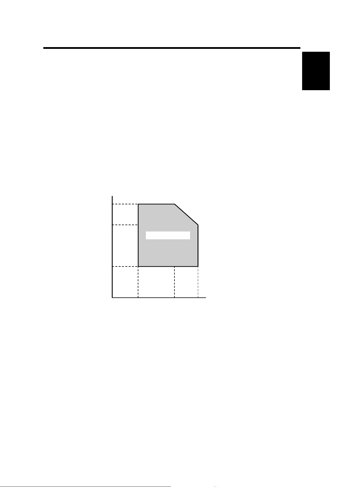
1.1.1 OPERATING ENVIRONMENT
1. Temperature Range:
2. Humidity Range:
3. Ambient Illumination: Less than 1,500 lux (do not expose to direct sunlight or
4. Ventilation: Room air should turn over at least 3 times per hour
5. Ambient Dust: Less than 0.10 mg/m
Humidity
80%
54%
Recommended: 15°C to 25°C (59°F to 77°F)
Possible: 10°C to 32°C (50°F to 90°F)
15% to 80% RH (27°C 80%, 32°C 54%)
strong light.)
3
Operation range
Installation
15%
10°C
(50°F)
27°C
(80.6°F)
32°C
(89.6°F)
Temperature
B039I502.WMF
6. If the place of installation is air-conditioned or heated, do not place the machine
where it will be:
1) Subjected to sudden temperature changes
2) Directly exposed to cool air from an air-conditioner
3) Directly exposed to heat from a heater
1-1
Page 22

INSTALLATION REQUIREMENTS 26 April, 2002
7. Do not place the machine where it will be expos ed to corrosive gases.
8. Do not install the machine at any location over 2,000 m (6,500 feet) above sea
level.
9. Place the copier on a strong and level base with the front and back of the
machine within ±5 mm (0.2") of level.
10. Do not place the machine where it may be subjected to strong vibrations.
11. Do not connect the machine to a power source shared with another electrical
appliance.
12. The machine can generate a an electromagnetic field which could interfere with
radio or television reception.
1.1.2 MACHINE LEVEL
1. Front to back:
2. Right to left:
The machine legs may be screwed up or down in order to level the machine. Set a
carpenter’s level on the exposure glass.
Within ±5 mm (0.2") of level
Within ±5 mm (0.2") of level
1-2
Page 23
26 April, 2002 INSTALLATION REQUIREMENTS
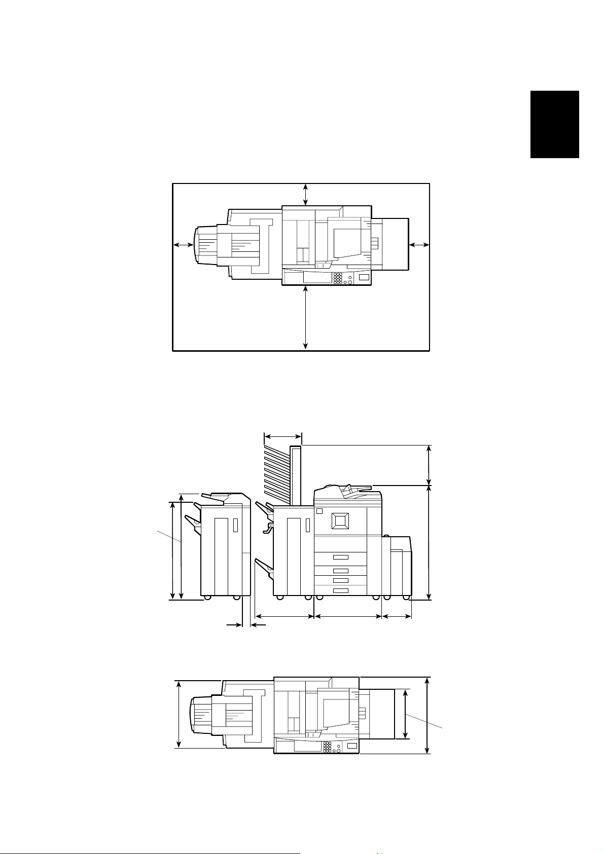
1.1.3 MINIMUM SPACE REQUIREMENTS
Place the copier near the power source, providing minimum clearance as shown
below. The same amount of clearance is necessary when optional peripheral
devices are installed.
50 mm (2") Back
Installation
100 mm (4") Left
1.1.4 DIMENSIONS
1,198 mm (43.2")
700 mm (27.6") Front
480 mm (18.9")
40 mm (1.6") Right
B064I001.WMF
425 mm (16.7")
1,165 mm (45.9")
1,014 mm (39.9")
620 mm (24.4")
90 mm (3.5")
690 mm (27.2")734 mm (28.9")
314 mm (12.4")
B064I003.WMF
750 mm (29.5")
458 mm (18")
B064I002.WMF
1-3
Page 24

INSTALLATION REQUIREMENTS 26 April, 2002
1.1.5 POWER REQUIREMENTS
!
CAUTION
1. Make sure that the wall outlet is near the main machine and easily
accessible. Make sure the plug is firmly inserted in the outlet.
2. Avoid multi-wiring.
3. Be sure to ground the machine.
4. Never set anything on the power cord.
North America 120 V, 60 Hz: More th an 12 AInput voltage level
Europe/Asia 220 V ~ 240 V, 50 Hz/60 Hz: more than 8 A
Permissible voltage fluctuation
!
CAUTION
Never turn off the main power switch when the power LED is lit or flashing.
To avoid damaging the hard disk or memory, press the operation power
switch to switch the power off, wait for the power LED to go off, and then
switch the main power switch off.
±10%
The Main Power LED (!) lights or flashes at the following times:
• While the platen cover or ADF is open
• While the main machine is communicating with the network server
• While the machine is accessing the hard disk or memory when reading or
writing data.
There are two power switches on the machine:
• Main Power Switch.
Located on the front left corner of the mac hine a nd cov er ed by a plastic cover.
This switch should always remain on unless the machine is being serviced.
• Operation Power Switch.
Located on the right side of the operation panel. This is the switch normally used
by the customer to power the machine on and off.
1-4
Page 25

26 April, 2002 MAIN MACHINE (B064/B065)
1.2 MAIN MACHINE (B064/B065)
1.2.1 ACCESSORY CHECK
Check the quantity and condition of the accessories in the box against the following
list:
Description Q’ty
1. Model Name Decal................................................................ 1
2. Operation Instructions............................................................ 2
3. NECR with Envelope............................................................. 1
4. Operation Panel Brand Decal................................................ 1
5. Paper Size Decal................................................................... 1
6. Decal – Face Up.................................................................... 1
7. Leveling Shoes...................................................................... 2
8. Operation Instruction Holder.................................................. 1
9. Decal – Cleaning ................................................................... 1
Installation
1-5
Page 26
MAIN MACHINE (B064/B065) 26 April, 2002
1.2.2 INSTALLATION PROCEDURE
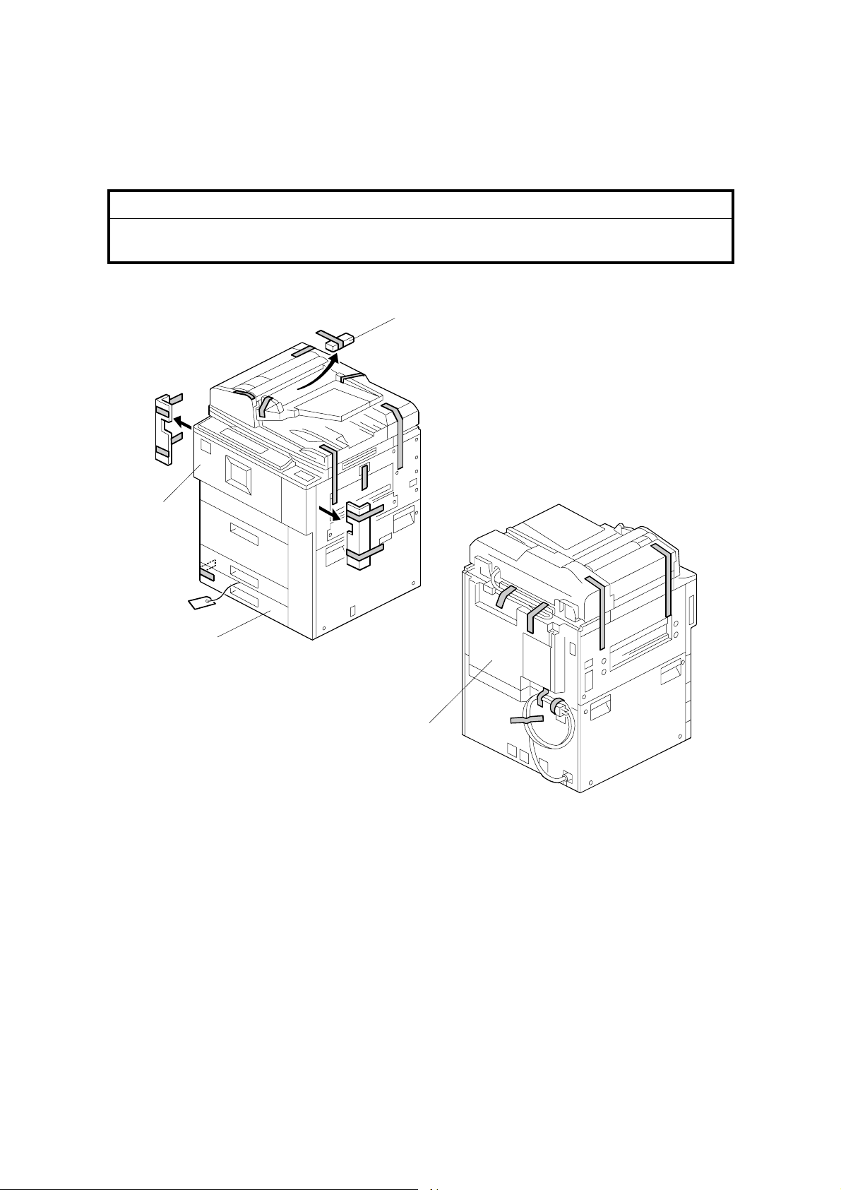
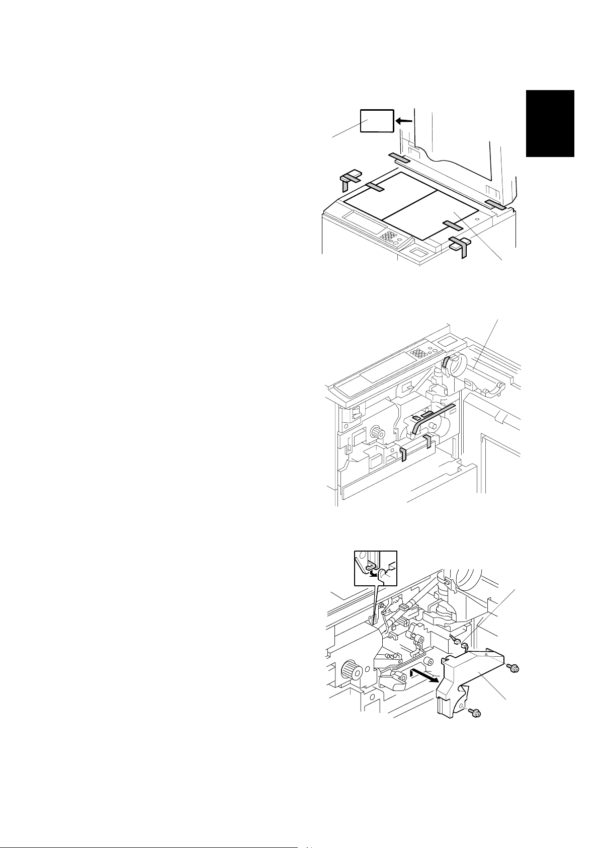
Removing Tapes and Retainers
!
CAUTION
To avoid serious injury, do not connect the power plug to the machine until
you are instructed to do so.
[C]
[A]
[B]
B064I403.WMF
[D]
1. Unpack the machine and remove all the wrapping.
2. Remove all filament tape from the front [A] of the machine.
B064I404.WMF
3. Open the lower tray [B] and remove the operating instructions holder and foot
risers.
4. Open the ADF feed cover and remove the tape and retainer [C].
5. Remove the tape from the back [D] of the machine.
NOTE: Save the filament tape and shipping retainers to prepare the machine
for shipping in the future.
1-6
Page 27
26 April, 2002 MAIN MACHINE (B064/B065)
6. Raise the ADF and remove all the
tape and shipping retainers around the
exposure glass [A] and operation
[B]
panel.
7. Remove the shipping retaining sheet
[B] under the white pad.
[A]
B064I005.WMF
[C]
8. Open the front door, open the toner
bottle holder [C], then remove all tape
and shipping retainers.
Installation
9. Remove the PCU inner cover [D] ("
x2) and disconnect the fan motor [E]
(# x 1).
B064I007.WMF
[E]
[D]
B064I008.WMF
1-7
Page 28
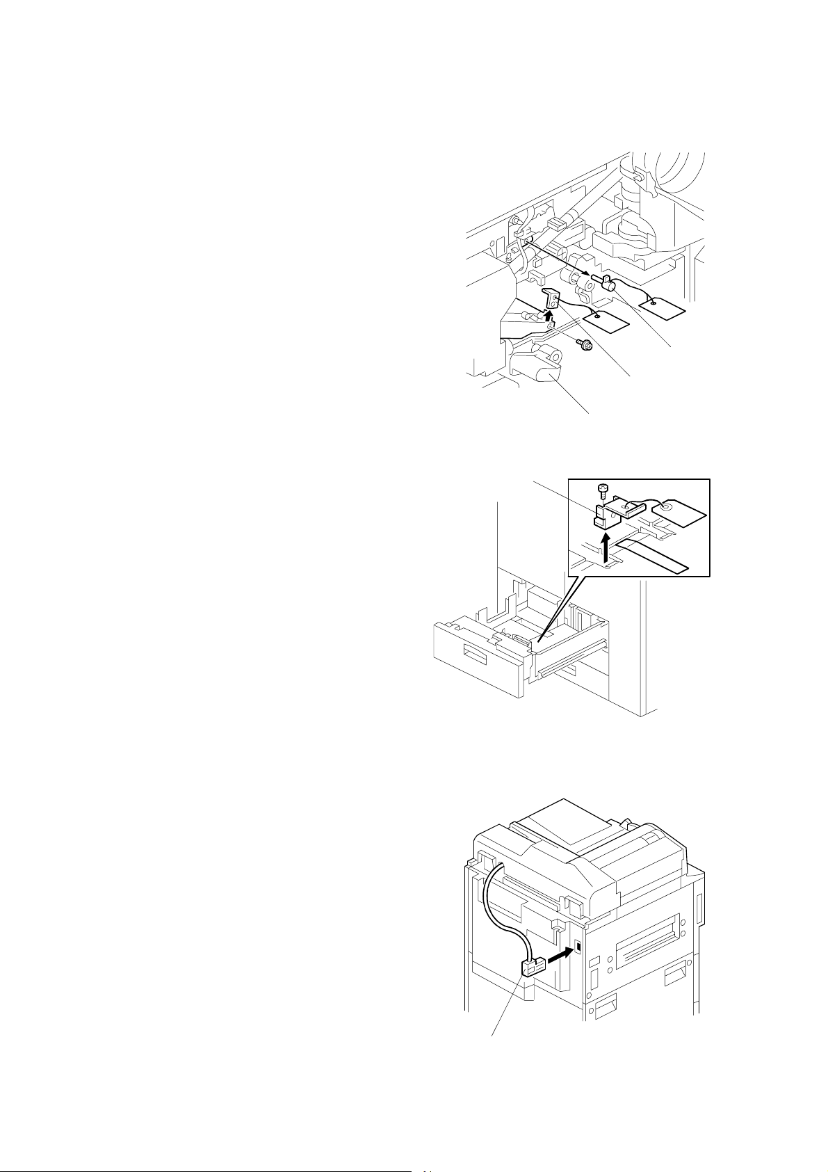
MAIN MACHINE (B064/B065) 26 April, 2002
10. Lower the transfer unit by turning its
knob [A].
11. Remove the bracket [B], and the red
tag from the transfer belt (" x1).
12. Remove the pin [C], and the red tag
from the cleaning plate.
[C]
[B]
13. Open the tandem tray (top paper
tray) and remove the metal retainer
bracket [D] (" x1), wire, and red tag.
Connecting the ADF
Connect the ADF plug [A] to the
connector on the back of the machine.
[D]
[A]
B064I009.WMF
B064I401.WMF
1-8
[A]
B064I405.WMF
Page 29
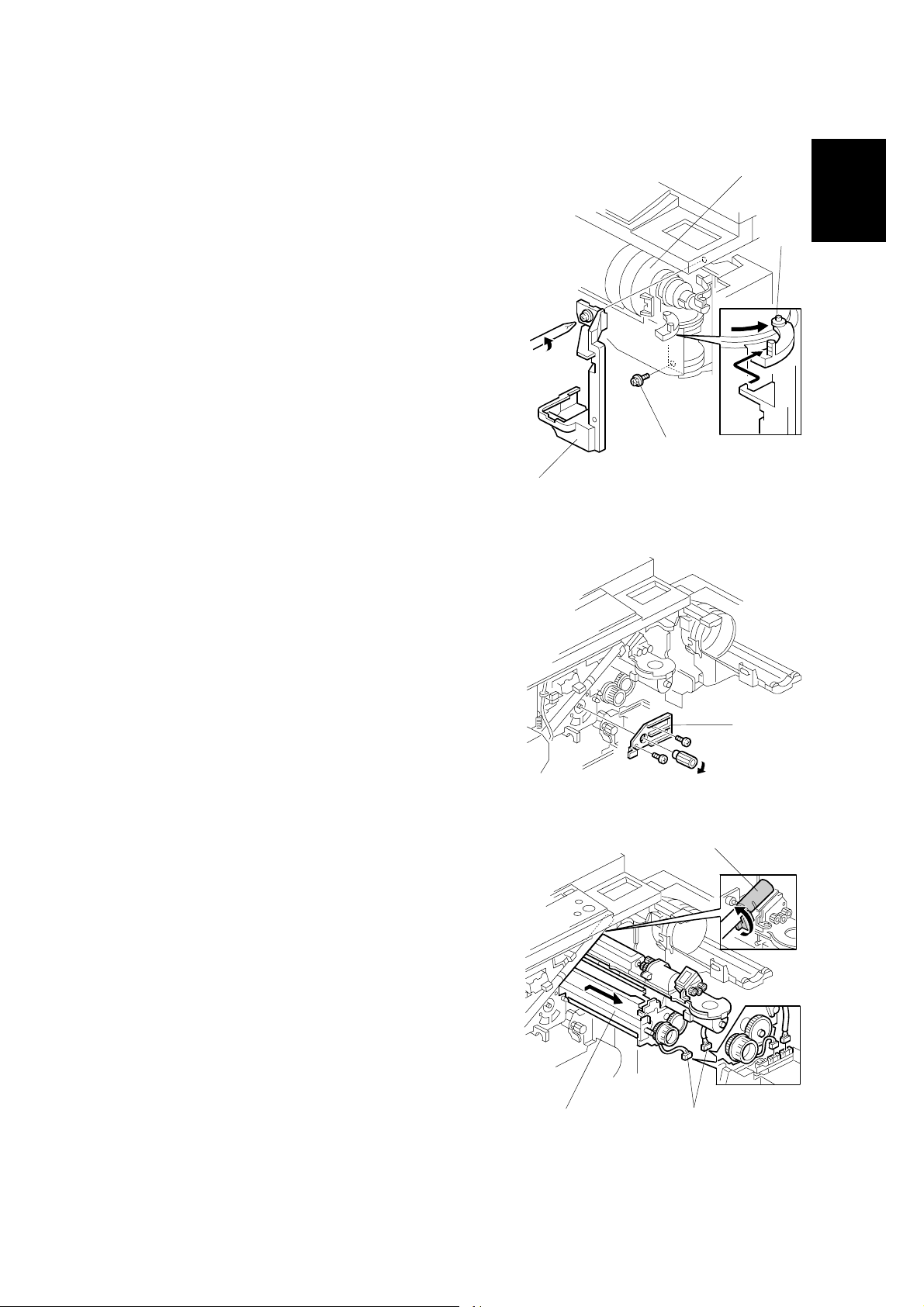
26 April, 2002 MAIN MACHINE (B064/B065)
Removing and Filling the Development Unit
1. Remove shutter cover [A] of the toner
supply unit (" x1).
2. Remove the lock screw [B] from the toner
bottle open/close bracket.
3. Make sure that the shipping tape at [C]
has been removed.
4. Pull the toner bottle holder out and swing
the toner bottle holder to the right.
NOTE: After re-installation, the tab [D]
should be behind the stay and
its pin below should be in the
open track below.
5. Remove the face plate [E] of the
development unit (knob x1, " x2).
[A]
[C]
Installation
[D]
[B]
B064I300.WMF
6. Disconnect the development unit [F]
(# x2).
NOTE: If the LCT is installed, you may
need to disconnect it so the front
door can open far enough to
allow removal of the
development unit.
7. Close the supply pipe shutter [G], and
then while allowing the development unit
[H] to slip to the right, slowly pull it out of
the machine.
[H]
[G]
[F]
[E]
B064I302.WMF
B064I303.WMF
1-9
Page 30

MAIN MACHINE (B064/B065) 26 April, 2002
8. Remove the toner hopper [A] (" x2).
9. Rotate the toner hopper [B] slightly
[A]
10° to 20° as you slide it up to
remove it.
[B]
B064I304.WMF
10. While turning the knob [C] slowly,
pour in one pack of developer [D]
from one end of the development
unit to the other.
NOTE: Make sure that the
developer is evenly
distributed. Note the
developer lot number
printed on the top edge of
the bag. You will need the
lot number when you
execute SP2963
(Installation Mode).
11. Assembly the developer unit then
re-install it in the machine.
12. Follow the instructions printed on
the inside of the front door to install
the toner bottle.
NOTE: If the door does not close,
make sure that the pipe line
shutter is rotated down.
(See Step 7 above.)
[D]
[C]
B064I305.WMF
1-10
Page 31

26 April, 2002 MAIN MACHINE (B064/B065)
Re-installing the Development Unit
[A]
B064I310.WMF
When re-installing the development unit, engage the plate ➀ on the front of the
development unit with the silver pin [A] inside the machine, then slide it to the left
➁
toward the drum.
If the unit is installed correctly, you should see the pin above the plate, and the
plate should be flat against the front of the development unit.
Installation
If the development unit will not move past the pin, the couplin gs are not aligned
correctly at the back of the machine. Turn the gear on the front of the developer
unit until the couplings engage at the rear of the machine.
Before closing the front door, make sure that the pipe line shutter is rotated down
to the open position.
1-11
Page 32

MAIN MACHINE (B064/B065) 26 April, 2002
Initializing the Drum Settings
After switching on the machine, you must execute SP2963 (Installation Mode)
within 60 seconds to 1) Initialize the developer and force toner supply to the
development unit, and 2) Initialize the auto process control settings.
• SP2963 must be executed before sample copying or test printing.
• If you do not press “Execute” in Step 2 in the following procedure within 60
seconds after the machine is switched on, the auto process control features
(potential sensor calibration, Vsg, Vref , et c.) will not initialize co rrectly.
• If the machine starts the auto process control routine before you have a chance
to press Execute, switch the machine off and try again.
1. Connect the power cord.
2. Within one minute, before the auto process control settings initialize, execute
SP2963.
• Press Clear Modes ".
• On the operation panel keypad, press #$%.
• Hold down Clear/Stop & for more than 3 seconds.
• Press “Copy SP” on the touch-panel.
• Press '()*.
• Press Enter +.
• Enter the Developer Lot No. with the key display, then press “Execute”.
About four minutes is required to initialize toner supply and the auto process
control settings.
3. Press “Exit” to leave the SP mode.
4. Attach the appropriate decals (provided) to the paper trays.
5. Check copy quality and machine operation.
NOTE: At installation, use SP2963 to enter the lot number, initialize the developer,
and to force toner supply to the toner hopper.
After replacing developer in a machine that has already been installed, do
not use SP2963; execute SP2801 (TD Sensor Initial Setting) instead to
enter the lot number and initialize the TD sensor. (☛ 3.7.1)
1-12
Page 33

26 April, 2002 MAIN MACHINE (B064/B065)
Tandem Tray
Before shipping the machine, the tandem tray is set for A4 or LT LEF and must be
adjusted if the customer wants to use the tandem tray for another paper size.
Feed Station Allowed Size
Tandem Tray (Tray 1) A4 LEF, LT LEF
Universal Trays (Trays 1, 2) A3, B4, A4 SEF, DLT, LG, LT SEF
1. Open the front cover.
2. Completely pull out the tandem feed
tray [A] so that the right tandem tray
[B] separates from the left tandem
tray.
Installation
[B]
[A]
B064I564.WMF
3. Remove the right tandem inner cover
[C].
4. Re-position the side fences [D] ("
x2). The outer slot position is used
when loading A4 size paper.
5. Re-install the right tandem in ner
cover [C].
[D]
[C]
B064I565.WMF
1-13
Page 34

MAIN MACHINE (B064/B065) 26 April, 2002
[B]
6. Remove the tray cover [A] (" x2).
7. Remove the motor cover [B] (" x4).
[A]
B064I566.WMF
[C]
8. Re-position the side fences [C] (" x8).
The outer slot position is used when
loading A4 size paper.
9. Re-install the motor cover and the tray
cover.
10. Remove the rear bottom plate [D]
(" x1).
11. Re-position the return position sensor
bracket [E] (" x1). To use the paper
tray for A4 size, put the screw in the
left hole as shown. (For LT size, the
screw should be placed on the right.)
12. Re-install the rear bottom plate.
B064I523.WMF
[D]
[E]
13. Change the paper size using SP5959001 (Paper Size – Tray 1). For details,
see SP5959 in section “5. Service
Tables”.
1-14
B064I024.WMF
Page 35

26 April, 2002 MAIN MACHINE (B064/B065)
Machine Level
1. Set a stand [A] at each corner of the
machine.
2. Place a level on the exposure glass
and use a wrench to turn each nut [B]
and level the machine to ±5 mm of the
horizontal.
3. Check the machine operation. With
[B]
the customer, determine the best
place to attach the cleaning reminder
decal.
Installation
[A]
Date/Time Setting
Use the User Tools menu to set the current date and time.
• On the operation panel, press the User Tools key.
• On the touch-panel, press “System Settings”.
• Press the “Timer Setting” tab.
• Press “Set Date” the enter the date.
• Press “Set Time” to enter the time.
SP Codes
SP5812 001~002
SP5841 001 Supply Name Setting
SP7825 Total Counter Reset
Service Telephone
Number Settings
– Toner Name
Setting: Black
Execute this SP and enter the contact
numbers of the custom engineer. Th ese are
the numbers displayed when a serv ice call is
issued.
This name appears when the user presses t he
Inquiry on the User Tools scre en.
Execute after installation and af t er maki ng al l
test copies to reset the electronic cou nt er
total.
B064I010.WMF
1-15
Page 36

A3/DLT FEEDER KIT (B475) 26 April, 2002
1.3 A3/DLT FEEDER KIT (B475)
1.3.1 ACCESSORY CHECK
Check the quantity and condition of the accessories in the box against the following
list:
Description Q’ty
1. A3/DLT Tray .......................................................................... 1
2. Short connector ..................................................................... 1
3. Page size decals.................................................................... 1
3
2
B475I001.WMF
1
1-16
Page 37

26 April, 2002 A3/DLT FEEDER KIT (B475)
1.3.2 INSTALLATION PROCEDURE
!
CAUTION
Switch the machine off and unplug the machine before starting the
following procedure.
1. Draw out the tandem tray completely
to separate the left and right sides of
the tray, then remove the front cover
[A] (" x2).
2. Push in the right tandem tray [B].
[B]
[A]
Installation
3. Remove the left tandem tray [C]
(" x5). Save these screws.
B475I707.WMF
[C]
B475I708.WMF
1-17
Page 38

A3/DLT FEEDER KIT (B475) 26 April, 2002
4. Remove the right tandem tray [A] ("
x2). Save these screws.
5. Connect the short connector [B] to the
right tandem tray terminal [C].
[A]
B475I709.WMF
6. Remove the stay [D] (" x2) and reinstall it.
7. Attach the A3/DLT tray [E], using the
screws removed earlier.
8. Re-install the front cover.
9. Switch the machine on, enter the SP
mode and select the paper size for
Tray 1 with SP5959 001 (Paper Size –
Tray 1) For details, see SP5959 in
section “5. Service Tables”.
10. Attach the appropriate decal for the
selected paper size.
[C]
[D]
[B]
B475I201.WMF
[E]
B475I202.WMF
1-18
Page 39

26 April, 2002 LCT (B473)
1.4 LCT (B473)
1.4.1 ACCESSORY CHECK
Check the quantity and condition of the accessories in the box against the following
list:
Description Q’ty
1. Flat-head shoulder screw - M4x6........................................... 1
2. Upper docking pins (grooved)................................................ 2
3. Lower docking pin (not grooved)............................................ 1
4. Installation Instructions .......................................................... 1
5. Paper Set Decal..................................................................... 1
Installation
1-19
Page 40

LCT (B473) 26 April, 2002
1.4.2 INSTALLATION PROCEDURE
Removing Tape
[B]
[A]
[C]
B473I001.WMF
B473I002.WMF
1. Remove the filament tape from the body [A] and top cover [B] of the LCT.
2. Remove the tape under the lid [C] of the LCT.
1-20
Page 41

26 April, 2002 LCT (B473)
Preparing the Main Machine
!
CAUTION
Switch the machine off and unplug the machine before starting the
following procedure.
1. Remove the LCT installation cover
[A] from the right side of the machine.
(# x2).
2. Save the screw on the left [B]. You
will need it to install the LCT.
[C]
3. Remove the LCT connector cover [C]
(x1) and the covers over the holes for
the docking pins [D]. (x3)
[A]
Installation
Installing the LCT
1. Insert the two upper docking pins
(grooved) [A] into the upper slots
and the lower docking pin [B] into
the lower slot.
[B]
[D]
B473I003.WMF
[A]
1-21
[B]
B473I004.WMF
Page 42

LCT (B473) 26 April, 2002
[D]
[C]
[B] [A]
2. Align the holes on the side of the LCT
[A] with the docking pins on the side of
the machine [B], then slowly push the
LCT onto the pins.
NOTE: The release button [C] is used
to unlock the LCT so it can be
disconnected from the
machine.
3. Connect the plug [D] of the LCT power
cord to the side of the machine.
4. Insert the flat-head shoulder screw [E]
into the hole and fasten it to lock the
release lever in place.
For easier access to the hole for the
screw [E], you can remove the right
panel [F] (" x2).
B473I005.WMF
[E]
[F]
B473I006.WMF
5. Switch the machine on and execute
SP5959 005 (Paper Size – Tray 4
(LCT)) to select the paper size. For
details, see SP5959 in section “5.
Service Tables.”
1-22
Page 43

26 April, 2002 LG/B4 FEEDER KIT (B474)
1.5 LG/B4 FEEDER KIT (B474)
1.5.1 ACCESSORY CHECK
Check the quantity and condition of the accessories in the box against the following
list:
Description Q’ty
1. Tapping screws - M4x8.......................................................... 4
2. Tapping hex screws - M4x8................................................... 6
3. Harness clamp....................................................................... 1
4. B4/LG frame .......................................................................... 1
5. Front bracket.......................................................................... 1
6. Rear bracket.......................................................................... 1
7. Bottom plate extension .......................................................... 1
8. Cover..................................................................................... 1
Installation
1-23
Page 44

LG/B4 FEEDER KIT (B474) 26 April, 2002
1.5.2 INSTALLATION PROCEDURE
If the LCT is connected to the machine
1. Open the cover and remove the paper.
[A]
2. Lower the LCT tray. Cover the near end
sensor [A], then press the tray down button
[B] to lower the tray bottom plate.
3. Disconnect the LCT from the machine
(☛ 1.4.2).
!
CAUTION
Switch the machine off and unplug the machine before starting the
following procedure.
[B]
B474I507.WMF
4. Remove the LCT upper cover [C].
[C]
B474I504.WMF
1-24
Page 45

26 April, 2002 LG/B4 FEEDER KIT (B474)
5. Remove the LCT cover [A] (" x1).
6. Remove the right stay [B] and reattach it below (" x2).
7. Remove the right cover [C] (" x2).
8. Attach the front bracket [D] with the
beveled corner down (" x2).
NOTE: If the brackets are difficult to
install, raise the bottom plate
with your hand.
9. Attach the rear bracket [E] with the
beveled corner down (" x2).
10. Attach the bottom plate extension [F]
with the hex nuts (" x4).
[B]
[C]
B474I001.WMF
[E]
[A]
[F]
Installation
11. Align the positioning pin [G].
12. Attach the B4/LG frame [H] with the
hex nuts (" x2).
The kit is set for B4. If you need to
change the paper size to LG, do the
following steps.
1-25
[D]
[H]
B474I502.WMF
[G]
B474I553.WMF
Page 46

LG/B4 FEEDER KIT (B474) 26 April, 2002
13. Move the front side fence [A] to the LG
position and fasten (" x1).
14. Move the rear side fence [B] to the LG
position and fasten (" x1).
15. Change the position of the lower limit
sensor [C] (" x1).
16. Attach the harness (not shown) to the
back of the plate and secure the
sensor connector wire.
[B]
[A]
B474I555.WMF
17. Attach the LCT cover [D] provided with
the kit (" x1).
18. Re-attach the right cover [E] (" x2).
19. Connect the LCT to the machine
(☛ 1.4.2).
20. Switch the machine on, enter the SP
mode, then use SP5959 005 (Paper
Size – Tray 4 (LCT) to select the new
paper size. For details, see SP5959 in
section “5. Service Tables”.
1-26
[C]
B474I508.WMF
[D]
[E]
B474I506.WMF
Page 47

26 April, 2002 3000-SHEET FINISHERS (B468/B469)
1.6 3000-SHEET FINISHERS (B468/B469)
1.6.1 ACCESSORY CHECK
Check the quantity and condition of the accessories in the box against the following
list:
Description Q’ty
1. Rear joint bracket................................................................... 1
2. Front joint bracket.................................................................. 1
3. Upper output tray................................................................... 1
4. Lower output tray................................................................... 1
5. Tapping screws - M3x6.......................................................... 2
6. Tapping screws - M4x8.......................................................... 4
7. Tapping screws - M4x14........................................................ 4
8. Cushion (with double-sided tape) .......................................... 1
9. Ground (earth) plate .............................................................. 1
10. Installation Instructions.......................................................... 1
Installation
1-27
Page 48

3000-SHEET FINISHERS (B468/B469) 26 April, 2002
1.6.2 INSTALLATION PROCEDURE
This section describes the common installation instructions for two peripheral
devices:
• B468 Finisher, capable of punching, shifting, stapling, and saddle-stitching with
staples.
• B469 Finisher, capable of punching, shifting, and stapling but with no saddle-
stitching unit.
NOTE: Differences in the installation procedure are noted as “B468” or “B469”.
Removing Tapes and Retainers
B469B468
B468I001.WMF
1. Unpack the machine and remove
all the wrapping.
2. Remove all filament tape and
shipping retainers from the front
of the finisher.
3. Open the front door [A] and
remove all the tape and shipping
retainers from inside the finisher.
B469I001.WMF
[A]
B468I002.WMF
1-28
Page 49

26 April, 2002 3000-SHEET FINISHERS (B468/B469)
B468/B469 Installation
!
CAUTION
Switch the machine off and unplug the machine before starting the
following procedure.
1. Install the front [A] and rear [B] joint
brackets (" x2 each, M4x14).
[B]
2. Install the ground plate [C] (" x2,
M3x6).
Installation
3. Peel the cover tape from the sponge
cushion [D], then install it in the upper
slot.
4. Remove the screw [E] to release the
lock lever (" x1).
5. Align the brackets [F] with the slots in
the finisher.
6. Slowly and carefully, to avoid bending
the entrance guide plates of the
finisher, push the finisher against the
side of the machine until the brackets
enter the slots.
7. Using the screw [E] removed above,
secure the lock lever [G] (" x1).
8. Connect the plug [H] of the finisher
power cord to the connector on the
machine.
[C]
[E]
[G]
[D]
[A]
B468I003.WMF
[H]
[F]
B468I004.WMF
!
CAUTION
Always move the finisher slowly to avoid bending the entrance guide
plates. Bent guide plates could interfere with paper transport from the
finisher to the machine.
1-29
Page 50

3000-SHEET FINISHERS (B468/B469) 26 April, 2002
[D]
B468
[C]
[B]
[A]
B468I005.WMF
B469
[E]
B468
1. Install the lower output tray [A] (" x2).
NOTE: Only the lower output tray has a movable support tray [B].
[F]
B469I005.WMF
2. Install the upper output tray [C] (" x2).
3. Attach the staple position decal [D] to the ADF.
B469
1. Install the output tray [E] (" x2).
2. Attach the staple position decal [F].
1-30
Page 51

26 April, 2002 3000-SHEET FINISHERS (B468/B469)
Selecting the Staple Supply Name
Enter the SP mode and execute the follow i ng informa ti on.
5841*
Supply Name Setting
005 Staple Std Enter the name of the staples in use for normal st apl ing
006 Staple Bind Enter the name of the staples in use for boo kl et stapling
These names appear when the user presses the Inquiry
button on the initial User Tools scre en.
(not booklet stapling). This set t i ng should be done for both
the B468 and B469.
(saddle-stitching). This setti ng i s requi r ed only for the
B468.
Enabling Booklet Binding
To enable booklet binding, you must select the ‘center stapling’ position.
1. Press the User Tools key.
2. Touch “Copier/Document Server Features”.
3. Touch the “Input/Output” tab, then access “Select Stapling Position”.
4. Touch any “Stapling Position” button and touch the center stapling symbol.
5. Exit the User Tools mode. Specify the number of copies, touch the center
stapling symbol on the operation panel, then start the print job.
These SP adjustments are available but not required at installation.
Installation
SP6902 Fold Position
Adjustment
SP6120
Staple Jogger
Adjustment
Use this SP to fine adjust the fold and staple positions if th ey
are not aligned correctly. See “5. Service Tables”.
Allows fine adjustment of the staple unit jogger fences for
different paper sizes, if required. See “5. Service Tables”.
1-31
Page 52

PUNCH UNIT (B377) 26 April, 2002
1.7 PUNCH UNIT (B377)
1.7.1 ACCESSORY CHECK
Check the quantity and condition of the accessories in the box against the following
list:
Description Q’ty
1. Punch unit.............................................................................. 1
2. Sensor arm............................................................................ 1
3. Hopper................................................................................... 1
4. Step screw............................................................................. 1
5. Spring.................................................................................... 1
6. Spacer (2 mm)....................................................................... 1
7. Spacer (1 mm)....................................................................... 1
8. Tapping screw - M3x8............................................................ 1
9. Tapping screw - M3x10.......................................................... 2
1-32
Page 53

26 April, 2002 PUNCH UNIT (B377)
1.7.2 INSTALLATION PROCEDURE
[A]
[B]
B377I201.WMF
Installation
[C]
[E]
[D]
B377I202.WMF
!
CAUTION
[F]
Switch off the main machine and unplug its power cord.
1. If the finisher is connected to the machine, disconnect it.
2. Unpack the punch unit and remove all tapes and shipping retainers.
3. Open the front door and remove the rear cover [A] (" x4).
4. Remove the bracket [B] (" x2) and paper guide [C] (" x1).
B377I103.WMF
5. Remove the plastic knockout [D].
6. Install the sensor arm [E] (" x1).
7. Install the spring [F].
1-33
Page 54

PUNCH UNIT (B377) 26 April, 2002
[A]
[C]
[B]
B377I203.WMF
[D]
B377I105.WMF
[F]
[E]
B377I106.WMF
8. Remove the shipping bracket [A] (" x2).
9. Position the 2 mm spacer [B] and secure the punch unit (" x2).
10. Secure the punch unit at the front with the shoulder screw [C] (" x1).
11. Connect the harnesses [D] and clamp them as shown.
NOTE: No special DIP switch settings are required for this punch unit. The
punch unit sends an identification signal to the machine, so it knows
what type of punch unit has been installed.
12. Slide the hopper [E] into the machine.
13. Fasten the two 1 mm spacers [F] to the rear frame. These may be used during
future adjustments.
NOTE: The spacers are used to adjust the horizontal positioning of the holes.
14. Reassemble the finisher an d check the punch op er ati o n.
1-34
Page 55

26 April, 2002 COVER INTERPOSER TRAY (B470)
1.8 COVER INTERPOSER TRAY (B470)
1.8.1 ACCESSORY CHECK
Check the quantity and condition of the accessories in the box against the following
list:
Description Q’ty
1. Shoulder screws.................................................................... 3
2. Upper front door extension.................................................... 1
3. Lower front door extension.................................................... 1
4. Lower cover extension........................................................... 1
5. Lower plate............................................................................ 1
6. Cover spacer ......................................................................... 2
*1
7. Tapping screws - M3x6.......................................................... 5
8. Tapping screws - M4x8.......................................................... 4
9. Tapping screws - M4x6.......................................................... 2
10. Installation Instructions.......................................................... 1
*1:
The extra spacer is provided for the B478 3000-Sheet Finisher.
Installation
1-35
Page 56

COVER INTERPOSER TRAY (B470) 26 April, 2002
1.8.2 INSTALLATION PROCEDURE
NOTE: If the B468/B469/B478 Finisher is connected to the machine, disconnect it.
Removing Tapes and Retainers
1. Remove all the filament tape and
shipping retainers.
2. Remove the cover [A] of the relay
connector.
3. Remove the bracket [B] (" x1).
NOTE: Loosen the screw. Do not
remove it.
4. Remove the guide plate [C]
(" x2).
[A]
B470I001.WMF
[B]
[C]
B470I002.WMF
1-36
Page 57

26 April, 2002 COVER INTERPOSER TRAY (B470)
[A]
[E]
[F]
[D]
[C]
Installation
[B]
B470I003.WMF
!
CAUTION
Switch the machine off and unplug the machine before starting the
following procedure.
5. Attach the three shoulder screws [A] (" x3).
6. Attach the bottom plate [B] (" x2, M3x6).
7. Remove the ground plate [C] from the finisher, then attach it to the bottom plate
(" x2, M3x6).
8. Attach the lower front door extension [D] (" x2, M4x8).
9. Attach the upper front door extension [E] (" x2, M4x8).
10. Attach the lower cover extension [F] (" x2, M4x6).
1-37
Page 58

COVER INTERPOSER TRAY (B470) 26 April, 2002
[D]
11. Insert the spacer [A] and snap it
[C]
into position.
12. Lower the transport guide plate [B].
13. Pick up the cover interposer, align
the keyholes [C] with the shoulder
screws [D], then set the cover
interposer onto the screws.
14. Secure the cover interposer with
the tapping screw [E] (" x1, M3x6).
15. Raise the transport guide plate [B]
to close it.
16. Take the sponge cushion [F] out of
the finisher and set it on the right
side of the cover interposer.
17. Attach the guide plate [G]
(removed from the finisher) to the
cover interposer (" x2).
18. Release the lock lever [H] on the
LCT (" x1).
19. Slowly and carefully, to avoid
bending the entrance guide plates
of the finisher, push the finisher
against the side of the machine
until the brackets [I] enter the slots.
20. Secure the lock lever [H] (" x1).
[H]
[A]
[F]
[B]
[G]
[I]
[E]
B470I004.WMF
B470I005.WMF
!
CAUTION
Dock the finisher carefully to avoid bending the entrance guide plates. Bent
guide plates could interfere with paper transport from the finisher to the
machine.
1-38
Page 59

26 April, 2002 9-BIN MAILBOX (B471)
1.9 9-BIN MAILBOX (B471)
1.9.1 ACCESSORY CHECK
Check the quantity and condition of the accessories in the box against the following
list:
Description Q’ty
1. Trays...................................................................................... 9
2. Guide plate ............................................................................ 1
3. Decals (bin display) ............................................................... 1
4. Tapping screws - M3x8.......................................................... 6
5. Installation Instructions .......................................................... 1
Installation
1-39
Page 60

9-BIN MAILBOX (B471) 26 April, 2002
1.9.2 INSTALLATION PROCEDURE
Removing Tapes and Retainers
1. Remove the filament tape [A].
NOTE: Handle the mailbox carefully.
The corner leaf [B] can be
damaged easily.
[A]
[B]
B471I001.WMF
Installation
!
CAUTION
Switch the machine off and unplug the machine before starting the
following procedure.
If the Cover Interposer Tray B470 is installed on the Finisher B468/B469, remove it.
The cover interposer tray and mailbox cannot be installed on the finisher at the
same time.
1. Remove the top cover [A] of the finisher
(" x1).
[A]
2. Remove the bracket [B] (" x1).
NOTE: Loosen the screw. Do not
remove it.
[B]
1-40
B471I002.WMF
Page 61

26 April, 2002 9-BIN MAILBOX (B471)
3. Attach the guide plate [A] to the top
of the finisher (" x2, M3x8).
4. Attach the mailbox [B] to the top of
the finisher (" x4, M3x8).
5. Attach the 9 trays [C] to the mailbox.
[A]
Installation
B471I003.WMF
[B]
[C]
[D]
6. Give the decals [D] to the customer
for notation and pasting at the
correct location.
B471I004.WMF
1-41
Page 62

PRINTER/SCANNER KIT (G338), PRINTER KIT (G339) 26 April, 2002
1.10 PRINTER/SCANNER KIT (G338), PRINTER KIT (G339)
1.10.1 ACCESSORY CHECK
Check the quantity and condition of the accessories in the box against the following
list:
Description Q’ty
1. Scanner/Printer DIMM (G338) or Printer DIMM (G339) ........ 1
2. Centronics Interface.............................................................. 1
3. NIB........................................................................................ 1
4. Screws - M3x8....................................................................... 2
5. Ferrite Core........................................................................... 1
6. Key Top Assembly ................................................................ 1
7. Operating Instructions – Printer............................................. 1
8. Installation Instructions.......................................................... 1
9. FCC Label ............................................................................ 1
10. Software CD-ROM ................................................................ 3
1-42
Page 63

26 April, 2002 PRINTER/SCANNER KIT (G338), PRINTER KIT (G339)
1.10.2 INSTALLATION PROCEDURE
Inserting DIMMs
Read this section carefully before installation so you know how to insert the DIMMs
correctly.
!
CAUTION
Follow the procedure below to connect the DIMMs to the controller board.
Incorrect insertion can damage the controller board or cause a bad
connection between the DIMM and controller contacts. If the upper contact
is pressed in and bent, the resulting poor connection could cause the
entire system to not operate.
[A]
[B]
Installation
[C]
G338I901.WMF
1. Hold the ROM DIMM with the edge connector [A] pointing toward the slot and
the notch [B] on the DIMM in the upper right corner.
2. Insert the edge connector [C] into the slot at a 30-degree angle from the
surface of the board.
NOTE: If the angle is too low, the upper contact could bend.
3. Move the outside edge of the ROM DIMM up and down slightly until it works
into the connector, then gently press it down level with the controller board.
1-43
Page 64

PRINTER/SCANNER KIT (G338), PRINTER KIT (G339) 26 April, 2002
Installation Procedure
[D]
[C]
[E]
G338I201.WMF
!
CAUTION
Switch the machine off and unplug the machine before starting the
following procedure.
NOTE: The printer/scanner unit requires at least 128 MB of memory (more is
recommended). Memory chips are not packaged with this unit.
[A]
[F]
[B]
1. Disconnect the ADF cable.
2. Remove the rear upper cover (" x2).
3. Remove the controller cover (" x10).
!
CAUTION
Make sure that the DIMMs are inserted correctly. (☛☛☛☛ 1.10.2)
4. Insert the SDRAM DIMM (expansion memory 128 MB or 256 MB) [A] into
PC133 on the controller.
5. Insert the ROM DIMM [B] (printer/scanner) board into Slot 1.
6. Remove the Centronics connector cover [C] and insert the Centronics
connector [D] into CN310 and fasten with the provided screws (" x2).
Rating voltage of interface connectors: Max. DC 5V
7. Remove the slot covers [E] (" x2).
8. Install the NIB [F] into CN311 (" x1).
Rating voltage of interface connectors: Max. DC 5V
1-44
Page 65

26 April, 2002 PRINTER/SCANNER KIT (G338), PRINTER KIT (G339)
9. Make sure that the following SP commands are set correctly.
• SP5811 – Machine No. Setting
• SP5907 – Plug & Play
10. Attach the provided decal near the machine name on the copier.
11. Wrap the Ethernet cable three times inside the ferrite core, close the ferrite
core, then connect the modular jack to the NIB.
12. Follow the procedures in the instruction manuals to perform the user settings.
13. Replace the key top assembly [G].
[G]
Installation
G338I402.WMF
1-45
Page 66

PS3 (B525-08) 26 April, 2002
1.11 PS3 (B525-08)
1.11.1 INSTALLATION PROCEDURE
[A]
B064I204.WMF
1. Remove the rear upper cover (" x2).
2. Remove the controller cover (" x9).
3. Insert the PS3 module [A] into Slot 2.
!
CAUTION
Make sure that the DIMM is inserted correctly. (☛☛☛☛1.10.2)
1-46
Page 67

26 April, 2002 USB 2.0 (B525-01)
1.12 USB 2.0 (B525-01)
1.12.1 ACCESSORY CHECK
Check the quantity and condition of the accessories in the box against the following
list:
Description Q’ty
1. USB 2.0 PCB......................................................................... 1
Installation
1-47
Page 68

USB 2.0 (B525-01) 26 April, 2002
1.12.2 INSTALLATION PROCEDURE
[A]
[B]
B064I202.WMF
!
CAUTION
Switch the machine off and unplug the machine before starting the
following procedure.
1. Remove the rear upper cover (" x2).
2. Remove the controller cover (" x9).
3. Remove the slot cover [A] (" x2).
4. Insert the USB board [B] into the PCI slot.
5. Fasten the slot cover to the USB board (" x2).
6. Use SP5990 005 to print a Self-Diagnostic Report with the system settings and
confirm that the machine correctly recognizes the interface.
1-48
Page 69

26 April, 2002 USB 2.0 (B525-01)
1.12.3 USB SP SETTINGS
The following SP commands are available. However, only one setting may require
adjustment and this setting should be performed only if the customer is
experiencing USB data transmission errors.
NOTE: Do not change the settings marked “DFU”. These settings are for design
and factory use only.
To enter the SP mode:
Installation
1. Press Clear Modes
"
2. On the operation panel keypad, press #$%.
3. Hold down Clear/Stop & for more than 3 seconds.
4. Press “Copy SP” on the touch-panel to open the SP command selection
screen.
14APR 2002 03:25
SP Mode (Service)
SP1XXX
SP2XXX
SP3XXX
SP4XXX
SP5XXX
SP6XXX
SP7XXX
SP8XXX
Feed
Drum
Process
Periphs
Data Log2
Scanner
Mode
Data Log
Close All Copy Window SP DirectOpen All
Group
COPY: SP1-001-001
Page
Line
Line
Page
Group
Initial 0
X-XXX-XXX
21
Prev Page Next Page
Exit
B064I999.WMF
5. Enter ,-...
SP No. Name Function
5844 001 Transfer Rate
5844 002 Vendor ID
5844 003 Product ID
5844 004 Dev. Release Num
Adjusts the USB transfer rate. Do not change the setting
unless there is a data transfer error using the USB high
speed mode.
HS/FS: High speed/Full speed auto adjust
(480Mbps/12Mbps)
FS: Full speed (12Mbps fixed)
Displays the vendor ID. DFU
Displays the product ID. DFU
Displays the development release version number. DFU
1-49
Page 70

IEEE1394 (G561) FIREWIRE INTERFACE 26 April, 2002
1.13 IEEE1394 (G561) FIREWIRE INTERFACE
1.13.1 ACCESSORY CHECK
Check the quantity and condition of the accessories in the box against the following
list:
Description Q’ty
1. IEEE-1394 Cable 2M 4PI...................................................... 1
2. IEEE-1394 Cable 2M 6PI...................................................... 1
3. PCB GW1394........................................................................ 1
1-50
Page 71

26 April, 2002 IEEE1394 (G561) FIREWIRE INTERFACE
1.13.2 INSTALLATION PROCEDURE
[A]
Installation
[B]
[C]
B064I205.WMF
!
CAUTION
Switch the machine off and unplug the machine before starting the
following procedure.
1. Remove the rear upper cover (" x2).
2. Remove the controller cover (" x9).
3. Remove the slot cover [A] (" x2).
4. Attach the IEEE1394 board [B].
5. Use the provided cable to connect the machine and the computer.
6. Make sure that the jumper is on TB2 [C].
7. Print a system settings list and confirm that the machine correctly recognizes
the interface.
1-51
Page 72

IEEE1394 (G561) FIREWIRE INTERFACE 26 April, 2002
1.13.3 UP MODE SETTINGS FOR IEEE 1394
Enter the UP mode and follow the procedure below to perform the initial interface
settings for IEEE 1394. These settings take effect every time the machine is
powered on.
1. Press User Tools/Counter.
2. On the touch panel, press System Settings.
3. Press Interface Settings.
System Intialization Settings End
Select the desired settings.
Network Parallel Interface
IP Address
Subnet Mask
IP Over 1394
SCSI Print
IEEE 1394 IEEE 802.1b
0000.0000.0000.0000
0000.0000.0000.0000
Enabled
Enabled
SCSI Print Bi-directional On
B064I998.WMF
4. Press the key and enter the following settings:
• IP Address
• Subnet Mask
• IP Over 1394. Enable or disable this setting as required. This setting enables
IP Over 1394 as the default setting for the printing method.
• SCSI Print. Enable or disable this setting as required. This setting enables
SCSI Print as the default setting for the printing method.
• SCSI Print Bi-directional. Switch bi-directional printing on or off for SCSI print.
1-52
Page 73

26 April, 2002 IEEE1394 (G561) FIREWIRE INTERFACE
1.13.4 SP MODE SETTINGS FOR IEEE 1394
The following SP commands can be set for IEEE 1394.
To enter the SP mode:
1. Press Clear Modes
"
2. On the operation panel keypad, press #$%.
3. Hold down Clear/Stop & for more than 3 seconds.
4. Press “Copy SP” on the touch-panel to open the SP command selection
screen.
14APR 2002 03:25
SP Mode (Service)
SP1XXX
SP2XXX
SP3XXX
SP4XXX
SP5XXX
SP6XXX
SP7XXX
SP8XXX
Feed
Drum
Process
Periphs
Data Log2
Scanner
Mode
Data Log
Close All Copy Window SP DirectOpen All
Group
COPY: SP1-001-001
Page
Line
Line
Page
Group
Initial 0
X-XXX-XXX
21
Prev Page Next Page
Exit
B064I999.WMF
5. Enter ,-*(.
Installation
SP No. Name Function
5839 004 Device Name
Sets the names for all the physical devices connected ot
the the IEEE 1394 firewire network.
5839 007 Cycle Master
Enables or disables cycle master function of the IEEE 1394
standard bus.
5839 008 BCR Mode Sets the BCR (Broadcast Channel Register) setting for the
Auto Node operation for the standard IEEE1394 bus for
when IRM is not in use. Three settings are available: 00,
01, 11.
5839 009 IRM 1394a Check
Determines whether an IRM check for IEEE 1394 is
conducted for the Auto Node when IRM is not used.
5839 010 Unique ID Enables the “Node_Unique_Id” setting for enumeration on
the standard IEEE 1394 bus.
5839 011 Logout Determines how successive initiator login in requests are
handled during login in for SBP-2.
5839 012 Login Enables or disables exclusive login for SBP-2.
5839 013 Login MAX
Sets the limit for the number of logins for SBP-2. Range: 1
~ 62.
1-53
Page 74

802.11B WIRELESS LAN (G628) 26 April, 2002
1.14 802.11B WIRELESS LAN (G628)
1.14.1 ACCESSORY CHECK
Check the quantity and condition of the accessories in the box against the following
list:
Description Q’ty
1. Wireless LAN PCB (GW-WLAN)........................................... 1
2. Antenna (GW-WLAN) (options)............................................. 2
3. Card (GW-WLAN) ................................................................. 1
4. Wireless LAN Insructions...................................................... 1
1-54
Page 75

26 April, 2002 802.11B WIRELESS LAN (G628)
1.14.2 INSTALLATION PROCEDURE
40 ~ 60 mm
[E]
Installation
[A]
[C]
[B]
[D]
!
CAUTION
B064I206.WMF
Switch the machine off and unplug the machine before starting the
following procedure.
1. Remove the rear upper cover (" x2).
2. Remove the controller cover (" x9).
3. Remove the slot cover [A] (" x2).
4. Insert the wireless LAN board [B] into the PCI Slot 1.
5. Fasten the slot cover to the wireless LAN board (" x2).
6. Set the jumper [C] between pins 3 and 4 on the wireless LAN board.
B064I207.WMF
7. Insert the LAN PC card [D] into the wireless LAN board.
8. Connect the antennas. Use the provided double-sided tape to attach the
antennas [E] to the side of the machine.
NOTE: 1) Set the antennas 40~60 mm apart (1.5~2.5”).
2) Attach the antennas where they will not be moved or damaged by
opening and closing the door of the machine.
3) Set up the antenna in an area that is free of interference from electrical
equipment that generates a strong electromagnetic field.
4) Always remove the antenna before moving the machine.
5) If reception is poor, move the machine and antenna closer to the access
point.
9. Print a system settings list and confirm that the machine correctly recognizes
the interface.
1-55
Page 76

802.11B WIRELESS LAN (G628) 26 April, 2002
1.14.3 UP MODE SETTINGS FOR WIRELESS LAN
Enter the UP mode and follow the procedure below to perform the initial interface
settings for IEEE 802.11. These settings take effect every time the machine is
powered on.
NOTE: The wireless LAN cannot be used if Ethernet is being used.
1. Press the User Tools/Counter key.
2. On the touch panel, press System Settings.
NOTE: The Network I/F (default: Ethernet) must be set for either Ethernet or
wireless LAN.
3. Select Interface Settings ! Network (tab) ! Network I/F Settting
4. Select either “Ethernet” or “IEEE 802.11b”.
5. Press IEEE 802.11b. Only the wireless LAN options are displayed.
System Intialization Settings
Select the desired settings.
Network Parallel Interface IEEE 1394
Transmission Speed
SSID Setting
Channel
WEP (Privacy) Setting
802.11 Ad Hoc Mode
ASSID
11
Disabled
IEEE 802.1b
Bandwidth Status
1/2
End
NextPrevious
B064I997.WMF
6. Transmission Mode. Select either “Ad Hoc Mode” or “Infrastructure Mode”.
7. SSID Setting. Enter the SSID setting. (The setting is case sensitive.)
8. Channel. This setting is required when Ad Hoc Mode is selected.
Range: 1 ~ 14 (default: 11)
NOTE: The allowed range for the channel settings may vary for different
countries.
1-56
Page 77

26 April, 2002 802.11B WIRELESS LAN (G628)
9. WEP (Privacy) Setting. The WEP (Wired Equivalent Privacy) setting is
designed to protect wireless data transmission. In order to unlock encoded
data, the same WEP key is required on the receiving side. There are 64 bit and
128 bit WEP keys.
Range of Allowed Settings:
64 bit 10 characters
128 bit 26 characters
10. Bandwidth Status. This setting is enabled only for the Infrastructure Mode.
Press here to display the current status of the bandwidth. One of the following
is displayed to reflect the reception status of the wireless LAN:
Good 76 ~ 100%
Fair 41 ~ 75%
Poor 21 ~ 40%
Unavailable 0 ~ 20%
11. Transmission Speed. Press the Next button to display more settings, then
select the transmission speed for the mode: Auto, 11 Mbps, 5.5 Mbps, 2 Mbps,
1 Mbps (default: Auto). This setting should match the distance between the
closest machine or access point, depending on which mode is selected.
NOTE: For the Ad Hoc Mode, this is the distance between the machine and
the closest PC in the network. For the Infrastructure Mode, this is the
distance between the machine and the closest access point.
Installation
11 Mbps 140 m (153 yd.)
5.5 Mbps 200 m (219 yd.)
2 Mbps 270 m (295 yd.)
1 Mbps 400 m (437 yd.)
12. To initialize the wireless LAN settings, use page 2/2. Press Execute to initialize
the following settings:
• Transmission mode
• Channel
• Transmission Speed
• WEP
• SSID
• WEP Key
1-57
Page 78

802.11B WIRELESS LAN (G628) 26 April, 2002
1.14.4 SP MODE SETTINGS FOR 802.11B WIRELESS LAN
The following SP commands can be set for 802.11b
1. Press Clear Modes
"
2. On the operation panel keypad, press #$%.
3. Hold down Clear/Stop & for more than 3 seconds.
4. Press “Copy SP” on the touch-panel to open the SP command selection
screen.
14APR 2002 03:25
SP Mode (Service)
SP1XXX
SP2XXX
SP3XXX
SP4XXX
SP5XXX
SP6XXX
SP7XXX
SP8XXX
Feed
Drum
Process
Scanner
Mode
Periphs
Data Log
Data Log2
Close All Copy Window SP DirectOpen All
Group
COPY: SP1-001-001
Page
Line
Line
Page
Group
Initial 0
X-XXX-XXX
21
Prev Page Next Page
Exit
B064I999.WMF
5. Enter ,-.$.
SP No. Name Function
5840 004 SSID Used to confirm the current SSID setting.
5840 006 Channel MAX Sets the maximum range of the channel settings for the
country.
5840 007 Channel MIN
5840 010 WEP Key Used to confirm the current WEP key setting.
5840 011 WEP Key Select Used to select the WEP key (Default: 00).
5840 020 WEP Mode Used to display the maximum length of the string that can
Sets the minimum range of the channels settings allowed
for your country.
be used for the WEP Key entry.
1-58
Page 79

26 April, 2002 PM TABLES
2. PREVENTIVE MAINTENANCE
2.1 PM TABLES
The amounts mentioned (K=1,000) as the PM interval indicate the number of prints
or copies unless stated otherwise. These numbers are based on the PM counter.
Symbol key: C: Clean, R: Replace, L: Lubricate, I: Inspect,
EM: Emergency Maintenance
!
WARNING
Turn off the main power switch and unplug the machine before performing
any procedure in this section. Laser beams can seriously damage the eyes.
2.1.1 MAIN MACHINE
EM 300K 450K 600K Expected K Note
SCANNER OPTICS
1st, 2nd, 3rd Mirror C C C Optics cloth
Exposure Glass C C C C Dry cloth or alcohol
Scanner Guide Rails L L L After cleaning with alcohol,
lubricate scanner guide rails
with Grease 501.
Toner Shield Glass C C C C Optics cloth
Reflector C C C Optics cloth
Preventive
Maintenance
EM 300K 450K 600K Expected K Note
AROUND THE DRUM
Charge Corona Grid R R 450 Blower brush.
Charge Corona Wire R C R 450 Alcohol, or clean damp cloth.
Charge Wire Cleaning
Pad
Cleaning Blade R R 500
Cleaning Brush R R 500
Charge Corona Casing C C Alcohol, or clean damp cloth.
Internal Dust Filter C C C Blower brush.
ID Sensor
Pick-off Pawls I I Replace if necessary.
Potential Sensor C C C Blower brush.
Quenching Lamp C C C Dry cloth.
Transfer Entrance Stay C C C Dry cloth.
Ozone Filter (Top) R R
Cleaning Filter R R
Cleaning Side Seal C C C Dry cloth.
Cleaning Entrance Seal C C C Dry cloth.
R R 450
CCC
Blower brush. Do SP 3001 002
after cleaning.
2-1
Page 80

PM TABLES 26 April, 2002
EM 300K 450K 600K Expected K Note
DEVELOPMENT UNIT
Developer R R (☛ 3.7.1)
Development Roller
Shaft
Development Roller C C
Development Filter R I R Blower brush.
Development Sleeve
Surface
Drive Gears C C C Blower brush.
Entrance Seal C C C Blower brush, dry cloth.
Side Seals C C C Blower brush, dry cloth.
Toner Bottle Holder C C C Dry cloth.
Paddle Roller Shaft C C C Blower brush, dry cloth.
Used Toner Separation
Unit
EM 300K 450K 600K Expected K Note
PAPER FEED
Registration Rollers C C Alcohol
Relay Rollers C C Alcohol
Paper Dust Mylar C C C Dry cloth
Registration Sensor C C Blower brush
Relay Sensor C C Blo wer brus h
Feed Rollers R R 450
Pick-up Rollers R R 450
Separation Rollers R R 450
By-pass Feed Rollers R R 450
By-pass Pick-up Rollers R R 450
By-pass Separatio n
Rollers
By-pass Paper End
Sensor
Grip Rollers C C Dry cloth, blower brush
Paper Feed Guide Plate C C Dry cloth
Vertical Transport
Rollers
Paper Feed Sensors C C C Blower brush
Paper End Sensors C C C Blower brush
CC
CCC
IR
R R 450
CC
CCC
Clean with blower brush and
dry cloth every time the
developer is replaced.
Dry cloth.
See NOTE below this table.
See NOTE below this table.
Dry cloth, blower brush
Alcohol
NOTE: Replace pick-up, feed and separation rollers as a set. Check the counter
value for each paper tray station with SP7204 (Copy Counter – Paper
Trays). If the value has reached 300K, replace the rollers. After replacing
the rollers, reset the counter with SP7816 (Copy Counter Reset).
2-2
Page 81

26 April, 2002 PM TABLES
EM 300K 450K 600K Expected K Note
TRANSFER BELT UNIT
Transfer Belt C R C 750
Transfer Roller
Cleaning Blade
Transfer Entrance
Guide Plate
Transfer Drive Roller C C Dry cloth
Transfer Drum Roller C C Dry cloth
Transfer Bias Roller C C Dry cloth
Transfer Exit Guide
Plate
Discharge Plate R R
EM 300K 500K 600K Expected K Note
FUSING UNIT AND PAPER EXIT
Cleaning Web R R
Cleaning Web Pressure
Roller
Cleaning Web Pressure
Roller Bearings
De-Curler Rollers C C Alcohol
Exit Rollers C C Alcohol
Exit Static Discharge
Brush
Fusing Entrance Guide
Plate
Fusing Exit Guide Plate C C Dry cloth.
Hot Roller R 600
Hot Roller Bearings R 1000
Hot Roller Strippers R R 600
Pressure Cleaning
Roller
Pressure Cleaning
Roller Bearings
Pressure Cleaning
Roller Spring Plate
Pressure Roller R 600
Pressure Roller
Bearings
Thermistors I I I
Transport Rollers C C Alcohol
Fusing Lamp I I I
CC
CC
CC
RR
RIR
R 750
R
R
II
II
I R I 600
Use dry cloth to clean transfer
belt. Always replace transfer
belt and transfer roller cleaning
blade together.
Dry cloth
Dry cloth
Replace roller and bushings
together.
Dry cloth.
Replace hot roller, bearings
together.
Replace as a set.
Replace pressure roller and
bearings together.
Preventive
Maintenance
2-3
Page 82

PM TABLES 26 April, 2002
EM 300K 450K 600K Expected K Note
DUPLEX
Entrance Sensor C C C Blower brush
Inverter Exit Rollers C C Alcohol
Transport Rollers C C Dry cloth
Reverse Trigger Rollers C C Dry cloth
Inverter Entrance Roller C C Dry cloth
Entrance Anti-Static
Brush
Reverse Junction Gate C C C Dry cloth
CC
Blower brush
2.1.2 ADF
EM 80K 160K 240K Expected K Note
The PM interval is for the number of originals that have been fed.
Pick-up Roller C R R R
Separation Roller C R R R
Paper Feed Belt C R R R
CIS Glass C C C Dry cloth
White Guide Plate C C C Dry cloth
Sensors C C C C Blower brush.
Platen Cover Sheet C C C C Water or alcohol
Drive Gears L L L Grease G501.
Transport Rollers C C C
Entrance Roller C C C
White Platen Roller C C C
Pre-Scanning Roller C C C
Scanning Roller C C C
Exit Roller CCC
Water or alcohol, belt cleaner
to clean paper feed belt.
Replace these items together.
Water or alcohol
2-4
Page 83

26 April, 2002 RELATED SP CODES
2.1.3 OPTIONAL PERIPHERAL DEVICES
LCT (Large Capacity Tray) B473
EM 300K 450K 600K Expected K Note
ROLLERS
Pick-up Roller R R 450
Feed Roller R R 450
Separation Roller R R 450
NOTE: Replace pick-up, feed and separation rollers as a set. Check the counter
value for each paper tray station with SP7204 (Copy Counter – Paper
Trays). If the value has reached 300K, replace the rollers. After replacing
the rollers, reset the counter with SP7816 (Copy Counter Reset).
Cover Interposer Tray B470
EM 80K 160K 240K Note
The PM interval is for the number of sheets that have been fed.
Feed Belt R R R
Pick-up Roller R R R
Separation Roller
Driver Rollers C C C
Idle Rollers C C C
Discharge Brush C C C
Bushings L Lubricate with silicone oil if noisy.
Sensors C C C Blower brush.
Feed Drive Gear L Lubricate with silicone oil if noisy.
RRR
Replace as a set.
Damp clean cloth.
See
below this table.
NOTE
Preventive
Maintenance
3000-Sheet Finisher with 50-sheet stapler and Saddle-Stitching B468B469
EM 300K 450K 600K Note
Driver Rollers C C C
Idle Rollers C C C
Discharge Brush C C C
Bushings L Lubricate with silicone oil if noisy.
Sensors C C C Blower brush.
Jogger Fences I I I Make sure screws are tight.
Dry cloth
2.2 RELATED SP CODES
This is a list of the PM related SP codes. For details, refer to Section “5 Service
Tables”.
7803* PM Counter Display Displays the PM cou nt since the last PM.
7804* PM Counter Reset Resets the PM count.
2-5
Page 84

26 April, 2002 GENERAL CAUTIONS
3. REPLACEMENT AND ADJUSTMENT
3.1 GENERAL CAUTIONS
Do not turn off either of the power switches while any of the electrical components
are active. Doing so might cause damage to units such as the transfer belt, drum,
and development unit when they are pulled out of or put back into the copier.
3.1.1 DRUM
An organic photoconductor (OPC) drum is more sensitive to light and ammonia gas
than a selenium drum. Follow the cautions below when handling an OPC drum.
1. Never expose the drum to direct sunlight.
2. Never expose the drum to direct light of more than 1,000 Lux for more than a
minute.
3. Never touch the drum surface with bare hands. When the drum surface is
touched with a finger or becomes dirty, wipe it with a dry cloth or clean it with
wet cotton. Wipe with a dry cloth after cleaning with wet cotton.
4. Never use alcohol to clean the drum; alcohol dissolves the drum surface.
5. Store the drum in a cool, dry place away from heat.
6. Take care not to scratch the drum as the drum layer is thin and is easily
damaged.
7. Never expose the drum to corrosive gases such as ammonia gas.
8. Always keep the drum in the protective sheet when keeping the drum unit, or
the drum itself, out of the copier. Doing so avoids exposing it to bright light or
direct sunlight, and will protect it from light fatigue.
9. Dispose of used drums in accordance with local regulations.
10. When installing a new drum, execute SP2962 (Adjustment of Drum
Conditions).
Adjustment
Replacement
3.1.2 DRUM UNIT
1. Before pulling o ut the drum unit, place a sheet of paper under the drum unit to
catch any spilt toner.
2. Make sure that the drum unit is set in position and the drum stay is secured
with a screw before the main switch is turned on. If the drum unit is loose, poor
contact of the drum connectors may cause electrical noise, resulting in
unexpected malfunctions (RAM data change is the worst case).
3. To prevent drum scratches, remove the development unit before removing the
drum unit.
3-1
Page 85

GENERAL CAUTIONS 26 April, 2002
3.1.3 TR ANSFER BELT UNIT
1. Never touch the transfer belt surface with bare hands.
2. Take care not to scratch the transfer belt, as the surface is easily damaged.
3. Before installing the new transfer belt, clean all the rollers and the in ner part of
the transfer belt with a dry cloth to prevent the belt from slipping.
3.1.4 SCANNER UNIT
1. When installing the exposure glass, make sure that the white paint is at the rear
left corner.
2. Clean the exposure glass with alcohol or glass cleaner to reduce the amount of
static electricity on the glass surface.
3. Use a cotton pad with water or a blower brush to clean the mirrors and lens.
4. Do not bend or crease the exposure lamp flat cable.
5. Do not disassemble the lens un it. Doing so will throw the lens and the copy
image out of focus.
6. Do not turn any of the CCD positionin g screws. Doing so will throw the CCD out
of position.
3.1.5 LASER UNIT
1. Do not loosen the screws that secure the LD drive board to the laser diode
casing. Doing so would throw the LD unit out of adjustment.
2. Do not adjust the variable resistors on the LD unit, as they are adjusted in the
factory.
3. The polygon mirror and F-theta lenses are very sensitive to dust. Do not open
the optical housing unit.
4. Do not touch the glass surface of the polygon mirror motor unit with bare
hands.
5. After replacing the LD unit, do the laser beam pitch adjustment. Otherwise, an
SC condition will be generated.
3-2
Page 86

26 April, 2002 GENERAL CAUTIONS
3.1.6 CHARGE CORONA
1. Clean the corona wires with a dry cloth. Do not use sandpaper or solvent.
2. Clean the charge corona casing with water first to remove NOx based
compounds. Then clean it with alcohol if any toner still remains on the casing.
3. Clean the end block with a blower brush first to remove toner and paper dust.
Then clean with alcohol if any toner still remains.
4. Do not touch the corona wires with bare hands. Oil stains from fingers may
cause uneven image density on copies.
5. Make sure that the wires are correctly between the cleaner pads and that there
is no foreign material (iron filings, etc.) on the casing.
6. When installing new corona wires, do not bend or scratch the wire surface.
Doing so may cause uneven charge. Also be sure that the corona wires are
correctly positioned in the end blocks.
7. Clean the grid plate with a blower brush (not with a dry cloth).
8. Do not touch the charge grid plate with bare hands. Also, do not bend the
charge grid plate or make any dent in it. Doing so may cause uneven charge.
Adjustment
Replacement
3.1.7 DEVELOPMENT
1. Be careful not to nick or scratch the development roller.
2. Place the development unit on a sheet of paper after removing it from the
copier.
3. Never disassemble the development roller assembly. The position of the doctor
plate is set with special tools and instruments at the factory to ensure the
proper gap between the doctor blade and the development roller.
4. Clean the drive gears after removing used developer.
5. Dispose of used developer in accordance with local regulations.
6. Never load types of developer and toner into the development unit other than
specified for this model. Doing so will cause poor copy quality and toner
scattering.
7. Immediately after installing new developer, the TD sensor initial setting
procedure should be performed with SP2810 (TD Sensor Initialization) to avoid
damage to the copier. Do not perform the TD sensor initial setting with used
developer. Do not make any copies before doing the TD sensor initial setting.
8. When using a vacuum cleaner to clean the develop ment unit casing, al ways
ground the casing with your fingers to avoid damaging the toner density sensor
with static electricity.
9. When replacing the TD sensor, replace the developer, then execute SP2801
(TD Sensor Initialization) and SP2962 (Adjustment of Drum Conditions).
3-3
Page 87

GENERAL CAUTIONS 26 April, 2002
3.1.8 CLEANING
1. When servicing the cleaning section, be careful not to damage the edge of the
cleaning blade.
2. Do not touch the cleaning blade with bare hands.
3. Before disassembling the cleaning section, place a sheet of paper under it to
catch any toner falling from it.
3.1.9 FUSING UNIT
1. After installing the fusing thermistor, make sure that it is in contac t with the hot
roller and that it is movable.
2. Be careful not to damage the edges of the hot roller strippers or their tension
springs.
3. Do not touch the fusing lamp and rollers with bare hands.
4. Make sure that the fusing lamp is positioned correctly and that it does not touch
the inner surface of the hot roller.
3.1.10 PAPER FEED
1. Do not touch the surface of the pick-up, feed, and separation rollers.
2. To avoid paper misfeeds, the side fences and end fence of the paper tray must
be positioned correctly to align with the actual paper size.
3.1.11 USED TONER
1. We recommend checking the amount of used toner at every EM.
2. Dispose of used toner in accordance with local regulations. Never throw toner
into an open flame, for toner dust may ignite.
3-4
Page 88

26 April, 2002 SPECIAL TOOLS AND LUBRICANTS
3.2 SPECIAL TOOLS AND LUBRICANTS
3.2.1 SPECIAL TOOLS
Part No. Description
A0069104 Scanner Positioning Pin (4 pcs./set)
A2929500 Test Chart – S5S (10 pcs./set)
A0299387 Digital Multimeter – FLU KE 87
N8036701 Flash Memory Card – 4 MB
N8036701 Case – Flash Memory Card
G0219350 Loop Back Connector
3.2.2 LUBRICANTS
Part No. Description
A2579300 Grease Barrierta – JFE 5 5/2
52039502 Silicon Grease G- 501
Adjustment
Replacement
3-5
Page 89

OPERATION PANEL AND EXTERNAL COVERS 26 April, 2002
3.3 OPERATION PANEL AND EXTERNAL COVERS
3.3.1 OPERATION PANEL
[A]
[B]
B064R801.WMF
[A]: Shoulder screws (! x2)
[B]: Operation panel (" x1)
3.3.2 FRONT DOOR
[A]
[B]
B064R802.WMF
While supporting the front door [A] with one hand, press down on the hinge bracket
[B] then raise the door slightly to remove it.
3-6
Page 90

26 April, 2002 OPERATION PANEL AND EXTERNAL COVERS
3.3.3 RIGHT COVERS
[C]
[B]
[A]
Adjustment
Replacement
[E]
B064R803.WMF
[D]
1. LCT entrance guide cover [A] (! x2)
2. Right upper cover [B] (! x2)
• To remove the right cover, remove the LCT entrance guide plate, open the
by-pass tray, then slide the right upper cover down to remove it.
• When re-attachi ng, before tightening the screws make sure that 1) the tabs
[C] on the cover are engaged with the grooves on the machine, and 2) the
catches on the cover are engaged with the shoulder screws.
3. Lower right cover [D] (! x2)
• After removing the screws, slide the cover down to remove it.
• When re-attachi ng, before tightening the screws make sure that the t abs [E]
on the cover are engaged with the grooves on the machine.
3-7
Page 91

OPERATION PANEL AND EXTERNAL COVERS 26 April, 2002
3.3.4 LEFT COVERS
[A]
[B]
B064R804.WMF
[A]: Left upper cover (! x2)
• Slide down to remove.
• When re-attachin g, before tightening the scr ews make sure that 1) the tabs
on the cover are engaged with the grooves on the machine, and 2) the
catches on the cover are engaged with the shoulder screws.
[B]: Left lower cover (! x2)
• Slide down to remove.
• When re-attachin g, before tightening the scr ews make sure that the tabs on
the cover are engaged with the grooves on the machine.
3-8
Page 92

26 April, 2002 OPERATION PANEL AND EXTERNAL COVERS
3.3.5 REAR COVERS
[A]
[B]
Adjustment
Replacement
[C]
B064R805.WMF
[A]: Disconnect the ADF plug.
[B]: Rear upper cover (! x3)
• Slide down to remove.
• When re-attachin g, before tightening the scr ews make sure that the tabs on
the cover are engaged with the shoulder screws.
[C]: Rear lower cover (! x2)
• When re-attachin g, before tightening the scr ews make sure that the tabs on
the cover are engaged with the shoulder screws.
3-9
Page 93

SCANNER 26 April, 2002
3.4 SCANNER
3.4.1 ADF AND TOP COVERS
ADF
[D]
B064R907.WMF
[C]
[A]
[B]
[E]
[E]
Rear upper cover. (☛ 3.3.5)
[A]: Cable bracket (! x1)
[B]: Controller/IPU panel (! x2)
• Swing open the panel so you can see the back.
[C]: Connector cover (! x2)
[D]: Connector (2nd from the top) (" x1)
[E]: ADF base left and right plates (! x2)
• While holding the ADF firmly, slide the ADF back and lift the large end of the
keyholes over the shoulder screws.
3-10
B064R906.WMF
Page 94

26 April, 2002 SCANNER
Top Covers
[A]
[B]
[C]
[D]
Adjustment
Replacement
ADF (☛ 3.4.1)
[A]: Top inside cover (! x2)
[B]: Top left cover (! x1)
[C]: Top right cover (! x1)
[D]: Operation panel (! x1) (☛ 3.3)
B064R010.WMF
3-11
Page 95

SCANNER 26 April, 2002
3.4.2 EXPOSURE GLASS
[A]
[B]
[D]
[C]
B064R001.WMF
[A]: Rear scale (! x3)
[B]: Left cover (! x3)
[C]: ADF exposure glass
[D]: Exposure glass
NOTE: Lift out the exposure glass and left scale together. The left scale is
permanently attached to the exposure glass with double-sided tape. Do not
remove the left scale from the exposure glass.
When re-installing the exposure glass:
• Position the exposure glass first. Make sure that the arrow mark is in the upper
left corner.
• When re-insta lling the left cover, make sure it is seated correctly.
3-12
Page 96

26 April, 2002 SCANNER
3.4.3 SCANNER ORIGINAL SIZE SENSORS
[A]
[B]
B064R004.WMF
Adjustment
Replacement
Exposure glass (☛ 3.4.2)
[A]: Original length sensor (! x1, " x1)
NOTE: In North America, two length sensors are provided.
[B]: Original width sensor (! x1, " x1)
3-13
Page 97

SCANNER 26 April, 2002
3.4.4 LENS BLOCK
[A]
[C]
[D]
[B]
B064R002.WMF
B064R003.WMF
Exposure glass (☛ 3.4.2)
Operation panel (☛ 3.3)
[A]: Top right cover (! x1)
[B]: Right upper stay (! x2)
[C]: Lens cover (! x2)
[D]: Lens block (! x2, " x3)
NOTE: To avoid damaging the lens block, never set it down on the side with the
PCB; turn it over with the PCB up.
Re-assemble the machine, then perform the scanner and printer adjustments.
(☛ 3.14)
3-14
Page 98

26 April, 2002 SCANNER
3.4.5 EXPOSURE LAMP
[D]
[B]
[A]
[C]
B064R005.WMF
Adjustment
Replacement
Exposure glass (☛ 3.4.2)
Push the 1st scanner [A] to the cutout [B] in the scanner frame.
[C]: Exposure lamp cover (! x2)
[D]: Exposure lamp (! x3, " x1)
NOTE: Never touch the surface of the exposure lamp with bare fingers.
3-15
Page 99

SCANNER 26 April, 2002
3.4.6 LAMP REGULATOR
[A]
[B]
[C]
B064R073.WMF
Operation panel (☛ 3.3.1)
Exposure glass (☛ 3.4.2)
Exposure lamp cover and exposure lamp (☛ 3.4.5)
[A]: Metal strip reflector
NOTE: Avoid touching the surface of the reflector and do not bend it.
[B]: Lamp regulator ribbon connector
[C]: Lamp regulator (! x 4, " x1)
3-16
Page 100

26 April, 2002 SCANNER
3.4.7 SCANNER MOTOR DRIVE BOARD (SDRB)
[A]
Adjustment
Replacement
Rear upper cover (☛ 3.3.5)
[A]: Scanner motor drive board (! x3, " x3)
B064R007.WMF
3-17
 Loading...