

Ricoh af1013 Service Manual

FAX UNIT
(Machine Code: B465)
SERVICE MANUAL
This manual explains the Fax Unit, as well as the following.
!
Handset (Machine Code: B433 - NA only)
24 July, 2001
Subject to change.

Lithium Batteries
!
CAUTION
The danger of explosion exists if battery on the FCU is incorrectly replaced.
Replace only with the same or an equivalent type recommended by the
manufacturer. Discard used batteries in accordance with the
manufacturer’s instructions.

TABLE OF CONTENTS
1 INSTALLATION ........................................................................... 1-1
1.1 INSTALLATION REQUIREMENTS...........................................................1-1
1.1.1 ENVIRONMENT...............................................................................1-1
1.1.2 MACHINE LEVEL.............................................................................1-1
1.1.3 MINIMUM SPACE REQUIREMENTS...............................................1-1
1.1.4 POWER REQUIREMENTS..............................................................1-1
1.2 FAX UNIT..................................................................................................1-2
1.2.1 ACCESSORY CHECK......................................................................1-2
1.2.2 INSTALLING THE FAX OPTION......................................................1-3
1.2.3 INITIAL PROGRAMMING.................................................................1-3
1.3 HANDSET.................................................................................................1-7
1.3.1 ACCESSORY CHECK......................................................................1-7
1.3.2 INSTALLATION PROCEDURE........................................................1-7
2 PREVENTIVE MAINTENANCE.................................................... 2-1
2.1 SPECIAL TOOLS AND LUBRICANTS......................................................2-1
2.2 PM TABLE.................................................................................................2-1
3 REMOVAL AND REPLACEMENT............................................... 3-1
3.1 PRECAUTION...........................................................................................3-1
3.2 FCU...........................................................................................................3-1
3.3 NCU...........................................................................................................3-1
3.4 MONITOR SPEAKER................................................................................3-1
4 TROUBLESHOOTING ................................................................. 4-1
4.1 ERROR CODES........................................................................................4-1
4.2 FAX SC CODES........................................................................................4-9
5 SERVICE TABLES....................................................................... 5-1
5.1 SERVICE LEVEL FUNCTIONS.................................................................5-1
5.1.1 HOW TO ENTER AND EXIT SERVICE MODE................................5-1
5.1.2 FUNCTION NO.................................................................................5-1
(1) 01. BIT SW......................................................................................5-1
(2) 02. PARAMETER LIST....................................................................5-2
(3) 03. ERROR CODE..........................................................................5-2
(4) 04. SERVICE REPORT...................................................................5-2
(5) 05. PROTOCOL DUMP...................................................................5-3
(6) 06. COUNTER R/W.........................................................................5-3
(7) 07. WORDING.................................................................................5-4
(8) 08. NCU...........................................................................................5-4
(9) 09. S.S. NUMBER...........................................................................5-5
(10) 10. WHITE ADJUST......................................................................5-5
i

5.2 BIT SWITCHES........................................................................................5-11
5.2.1 SYSTEM SWITCHES.....................................................................5-11
5.2.2 SCANNER SWITCHES..................................................................5-22
5.3.3 PLOTTER SWITCHES...................................................................5-27
5.3.4 COMMUNICATION SWITCHES.....................................................5-32
5.3.5 G3 SWITCHES...............................................................................5-37
5.4 NCU PARAMETERS...............................................................................5-45
5.5 DEDICATED TRANSMISSION PARAMETERS......................................5-56
5.5.1 PROGRAMMING PROCEDURE....................................................5-56
5.5.2 PARAMETERS...............................................................................5-57
5.6 SERVICE RAM ADDRESSES.................................................................5-60
6 DETAILED SECTION DESCRIPTIONS ....................................... 6-1
6.1 PCBS.........................................................................................................6-1
6.1.1 FCU..................................................................................................6-1
6.1.2 NCU ..................................................................................................6-1
SPECIFICATIONS.....................................................................SPEC-1
1. GENERAL SPECIFICATIONS.............................................................SPEC-1
2. FEATURES.........................................................................................SPEC-2
2.1 FEATURES LIST.........................................................................SPEC-2
2.2 CAPABILITIES OF PROGRAMMABLE ITEMS...........................SPEC-5
3. OVERALL MACHINE CONTROL........................................................SPEC-6
3.1 SYSTEM CONTROL...................................................................SPEC-6
3.2 POWER DISTRIBUTION.............................................................SPEC-6
3.3 MEMORY BACK-UP....................................................................SPEC-6
4. VIDEO DATA PATH............................................................................SPEC-7
4.1 TRANSMISSION.........................................................................SPEC-7
Memory Transmission and Parallel Memory Transmission...........SPEC-7
Immediate Transmission...............................................................SPEC-7
4.2 RECEPTION................................................................................SPEC-7
ii

24 July, 2001 INSTALLATION REQUIREMENTS
1. INSTALLATION
NOTES: 1) Never install telephone wiring during a lightning storm.
2) Never install a telephone jack in a wet location, unless the jack is
specifically designed for such a location.
3) Never touch uninsulated telephone wires or terminals unless the
telephone line has been disconnected at the network interface.
4) Use caution when installing and modifying telephone lines.
5) Avoid using telephones (other than cordless types) during an electrical
storm, as there may be a remote risk of electric shock from lightning.
6) Do not use a telephone in the vicinity of a gas leak. If you need to
report a leak, move to a different location before phoning.
!
CAUTION
1. Before installing the fax unit, switch off the main power and disconnect
the power cord.
2. The fax unit includes lithium battery(s). There is risk of explosion of a
battery of this type is replaced incorrectly. Replace only with the same
type or with an equivalent type recommended by the manufacturer.
Discard used batteries in accordance with the manufacturer’s
instructions.
Installation
1.1 INSTALLATION REQUIREMENTS
1.1.1 ENVIRONMENT
Refer to the service manual for the base copier.
1.1.2 MACHINE LEVEL
Refer to the service manual for the base copier.
1.1.3 MINIMUM SPACE REQUIREMENTS
Refer to the service manual for the base copier.
1.1.4 POWER REQUIREMENTS
Refer to the service manual for the base copier.
1-1

FAX UNIT 24 July, 2001
1.2 FAX UNIT
1.2.1 ACCESSORY CHECK
Confirm that you have the components and accessories indicated below.
No. Description Q’ty NA EU Asia
1
Fax operation panel
2 Monitor speaker 1 O O O
3 NCU (Network Control Unit) with bracket 1 O O O
4 Harness for NCU - FCU 1 O O O
5 FCU (Fax/Function Control Unit) 1 O O O
6 Copy Key Top 1 O O O
7 Screws 6 O O O
8 Super G3 decal 1 O O O
9
Handset bracket
10 Telephone cable 1 O – –
11 Label(s) 1 O – –
12 User function key decal 1 O V O
13 Operation panel sheet 1 # V #
14 Operators Instructions - Basic Featur es 1 O V O
Operators Instructions - Advanced
15
Features
16 Installation Procedure 1 O V O
1OOO
1O – –
1OV O
O: Included in package
V: Language kit
#: Adhered on the operation panel
1-2
24 July, 2001 FAX UNIT
1.2.2 INSTALLING THE FAX OPTION
!
CAUTION
1. Before starting installation, be sure to save the SRAM data (user
settings) from the existing FCU into an external memory card. After
completing the installation, load the save data into the new FCU.
2. If there is a printer option installed in the machine, proceed as follows.
1) Print out all print data from the printer buffer.
2) Remove the printer option from the machine.
3) Install the fax option.
4) Reinstall the printer option.
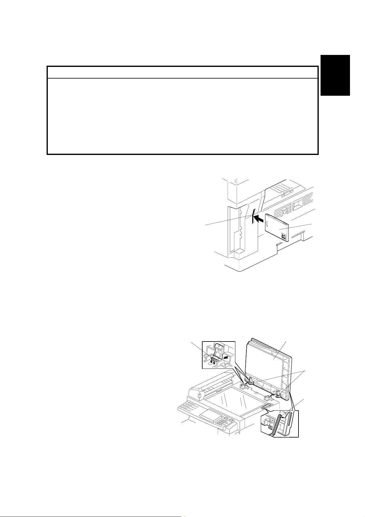
1. Turn the power off, and then insert a
memory card [A] into the card slot [B].
[B]
Installation
[A]
2. Turn the power on, and run SP5-824 to save
B465I500.WMF
(upload) the SRAM data from the current FCU into the memory card. (For
instructions, see Section 5.1.8 of the base copier's service manual.)
3. Turn off the main switch, remove the memory card, and disconnect the power
cord.
4. Remove the platen cover [C]. To
remove: Lift the cover, unlatch
[E]
[C]
the two latches [D] (press down
on the tabs [E] and push the
latch back), and detach the cover
from the hook [F].
[D]
[F]
B465I501.WMF
1-3
FAX UNIT 24 July, 2001
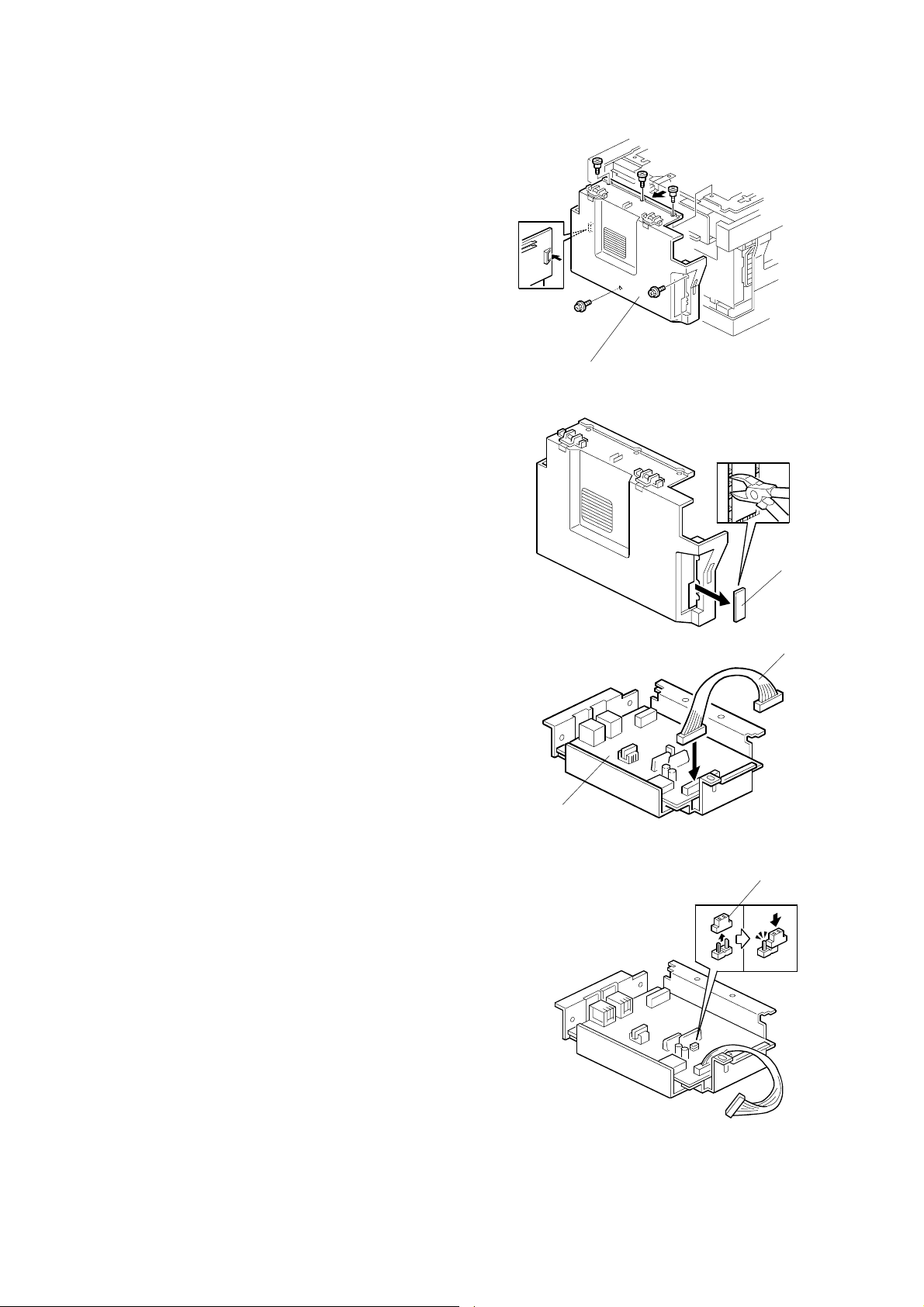
5. Remove the rear cover [A] (! x 5).
[A]
B465I502.WMF
6. Cut out area [B] from the rear cover.
7. Connect the supplied harness [C] to the
NCU [D].
8. On Hong Kong models only: On the NCU,
change the position of the TB1 jumper
connector [E] so that the jumper is open.
[B]
B465I503.WMF
[C]
[D]
B465I504.WMF
[E]
1-4
B465I505.WMF
24 July, 2001 FAX UNIT
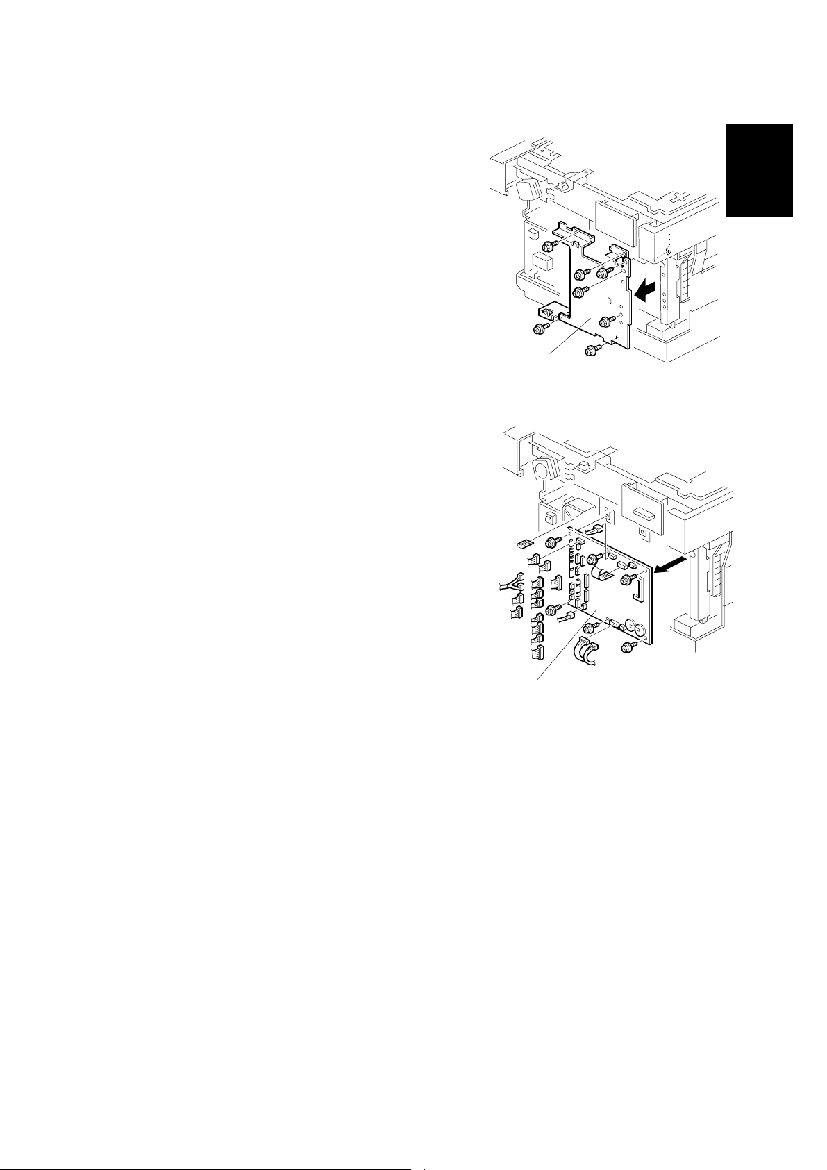
9. Remove the FCU cover plate [A] (! x 7).
[A]
Installation
10. Remove the FCU [B] that is currently
B465I506.WMF
installed on the machine (all connectors, 2 flat
cables, ! x 6).
[B]
B465I507.WMF
11. In place of the FCU that you just removed, install the FCU that came with the
fax option (! x 6, 2 flat cables, all connectors).
NOTE: Make sure that the battery switch on the FCU is turned on.
1-5
FAX UNIT 24 July, 2001
12. Reinstall the FCU cover plate that you removed
at Step 9.
13. Connect the supplied harness to CN1 on the NCU.
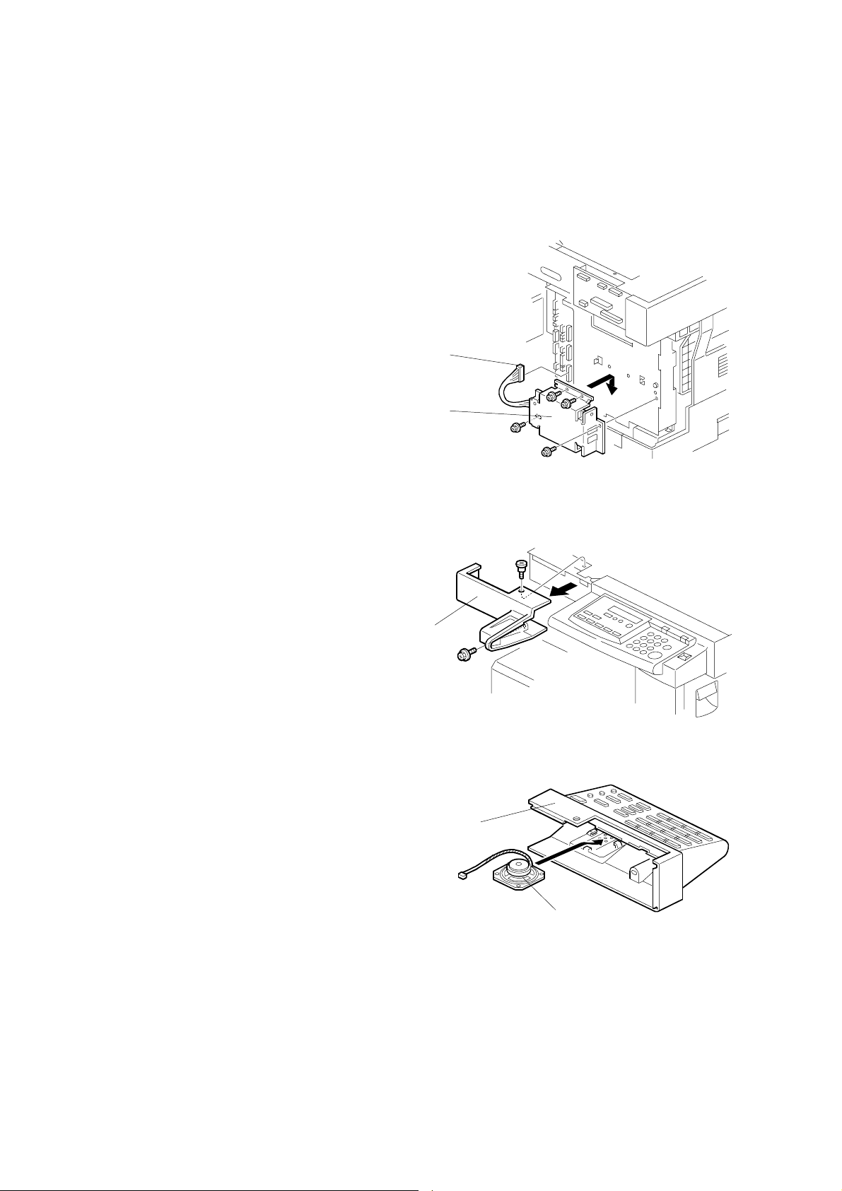
14. Attach the NCU-and-bracket [A] to the cover
plate with 4 of the supplied screws. Connect
the NCU cable [B] to CN33 on the FCU.
[B]
[A]
B046I136.WMF
15. Reattach the rear cover.
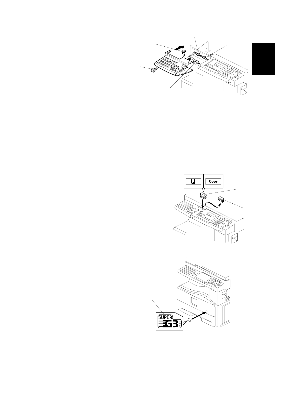
16. Remove the front left cover [C] (! x 2).
[C]
17. Set the monitor speaker [D] into the fax
operation panel [E], with the speaker
harness positioned as shown.
B465I510.WMF
[E]
[D]
B465I511.WMF
1-6
24 July, 2001 FAX UNIT
[B]
18. Connect the fax operation panel's
[E]
[C]
connector [A] to the connector on the
copier's operation panel.
[D]
[A]
B465I512.WMF
19. Connect the speaker's connector [B] to the connector [C] extending out from
the copier's operation panel.
20. Attach the fax operation panel to the copier with the 2 screws ([D] and [E])
removed at Step 15. For the upper screw [E], be sure to use the shorter,
headless screw.
NOTE: If you mistakenly use the longer screw at [E], the screw will block the
action of the scanner.
Installation
21. Remove the small cover [F], then attach the
copy key top [G].
22. Reattach the platen cover.
23. Affix the packed decal(s)/label(s) on the
front cover as shown.
Example: Super G3 decal [H]
[H]
[G]
[F]
B465I109.WMF
24. Insert the telephone cable into the
socket labeled “LINE” at the rear of the machine.
25. Plug in the machine and turn the main power switch on.
NOTE: Be sure to plug the machine in to a properly grounded outlet.
1-7
B465I111.WMF

FAX UNIT 24 July, 2001
26. Do the following to confirm that the fax unit is correctly installed. If results are
incorrect, go back and repeat the installation procedure.
1) Access SP5-992 and select "2" to print out a full SMC report. Confirm that
the report shows a "YES" for SP7-801-3.
2) Press the On Hook key on the fax operation panel, and confirm that you
hear a dial tone coming from the monitor speaker.
27. Turn the power off, and then insert the memory card that you used at Step 2 to
save the old FCU's SRAM data.
28. Turn the power on, and run SP5-825 to download the saved data from the card
into the new FCU. (For instructions, see Section 5.1.8 of the base copier's
service manual.)
29. Turn the power off, remove the memory card, and turn the power back on.
30. Program the items required for fax communication, as indicated below.
1-8
24 July, 2001 FAX UNIT
1.2.3 INITIAL PROGRAMMING
Items to Program (Service Level – Serv i ce Functions*1)Function No.
Country code (System switch 0F) 01
Protocol requirements (G3 switch 0 B) - E U only 01
PM call (System switch 01 – bit 0) 01
Country code (NCU parameter 0 0) 07
Service station's fax number 09
Items to Program (Service Level – SP Mode*1) SP No.
Machine's serial number 5-811
Language replacement (Fir mware download) 5-827
PSTN access code (RAM address 4000DB)
PSTN access method (RAM address 4000CD)
Periodic service call (RAM addresses 40054F to 400553)
*1: See Section 5.1.1 f or information about how to enter service functions.
Items to Program (User Administrator Level) User Tools
Monitor volume
Display contrast
Date and Time
Reception mode
Fax Header/Own Name/Own No. (TTI/RTI/CSI)
Reports on/off
Country Code (except NA)
Energy saver level System Settings
Language selection Language
Other initial progr amming items *2
7-955
Fax Features ->
Setup
Key Op. Tools
Installation
*2: Refer to the Operating Instructions for details.
1-9
HANDSET (OPTION FOR NA) 24 July, 2001
1.3 HANDSET (OPTION FOR NA)
1.3.1 ACCESSORY CHECK
Check that you have the components and accessories indicated below.
No. Description Q’ty
1
2
3
4 Handset manual 1
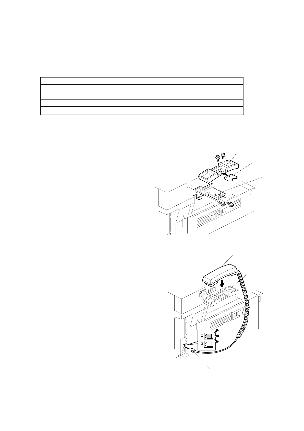
1.3.2 INSTALLATION PROCEDURE
Handset 1
Handset cradle 1
Screws 2
1. Attach the handset bracket [A]
included with the fax option, using
2 of the screws included with that
option.
2. Remove the label [B] from the handset
cradle [C]. Attach the cradle [C] to the
bracket [A] using the two supplied
screws. Then reattach the label.
3. Set the handset [D] on the cradle [C],
and then connect the cable [E] to the
TEL jack at the rear of the machine.
[C]
[B]
[A]
B465I514.WMF
[D]
[C]
1-10
[E]
B465I515.WMF

24 July, 2001 SPECIAL TOOLS AND LUBRICANTS
2. PREVENTIVE MAINTENANCE
2.1 SPECIAL TOOLS AND LUBRICANTS
• Flash Memory Card – 4MB (P/N: N8036701)
• Card Case (P/N: N8031000)
2.2 PM TABLE
No PM necessary for the fax option.
Preventive
Maintenance
2-1
24 July, 2001 PRECAUTION
3. REMOVAL AND REPLACEMENT
3.1 PRECAUTION
!
CAUTION
Before starting disassembly, be sure to print all message files in the SAF
memory. Then, turn off the main power switch and disconnect the power
cord and telephone cable for safety.
Lithium Battery
The danger of explosion exists if a battery of this type is incorrectly
replaced. Replace only with the same type or with an equivalent type
recommended by the manufacturer. Discard used batteries in accordance
with the manufacturer’s instructions.
3.2 FCU
Adjustment
Replacement
Refer to the service manual for the base copier.
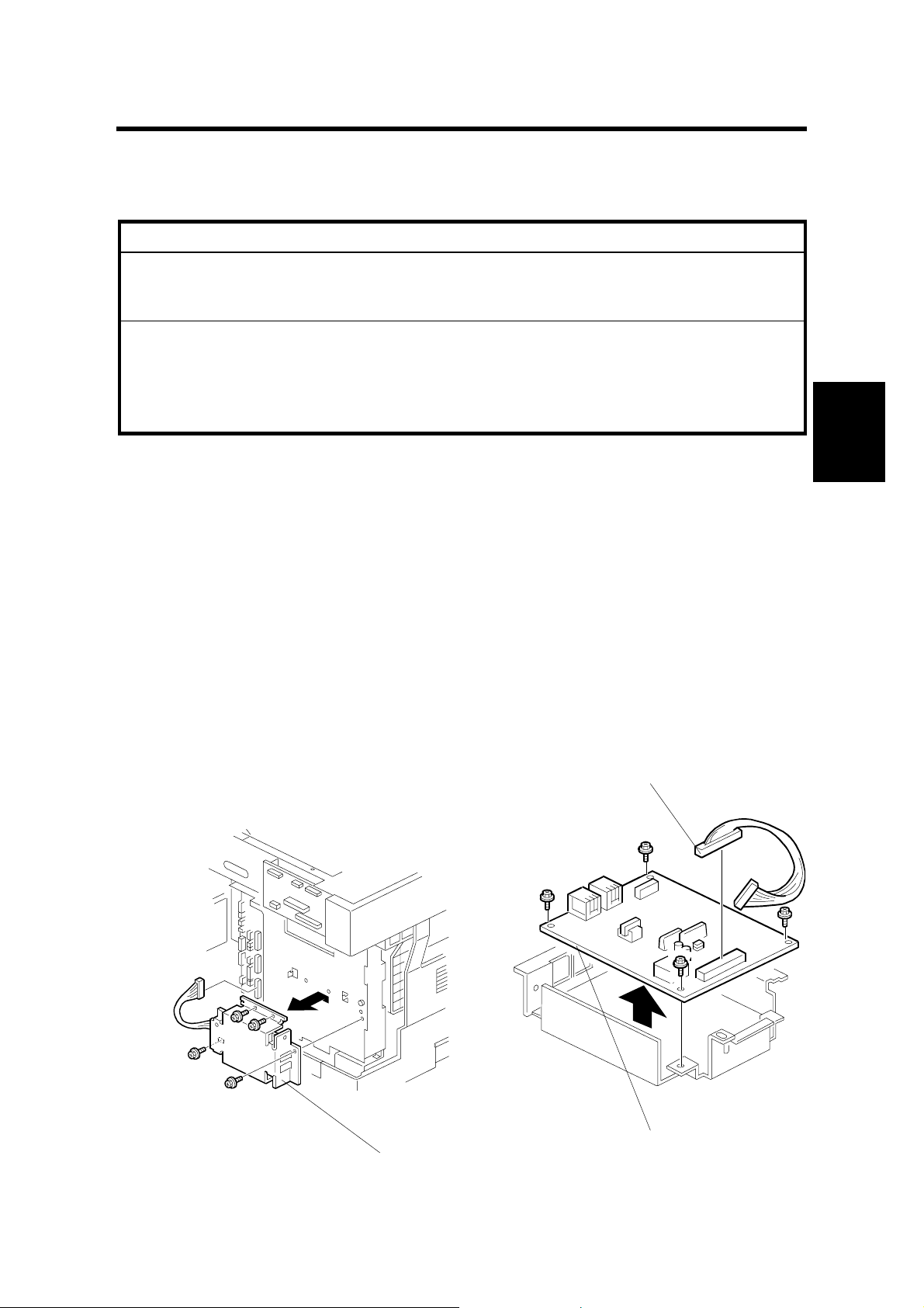
3.3 NCU
1. Rear cover (Refer to service manual for the base copier.)
2. NCU bracket (! × 4 ) [A]
3. Disconnect the harness [B] from the NCU.
4. NCU [C] (! × 4)
[B]
B046I120.WMF
[A]
B465R135.WMF
[C]
3-1

MONITOR SPEAKER 24 July, 2001
3.4 MONITOR SPEAKER
1. Fax operation panel [A] (! × 2, " × 2)
2. Speaker [B]
[A]
B465I512.WMF
[B]
B441I105.WMF
3-2

24 July, 2001 ERROR CODES
4. TROUBLESHOOTING
4.1 ERROR CODES
If an error code occurs, retry the communication. If the same problem occurs, try to
fix the problem as suggested below. Note that some error codes appear only in the
error code display and on the service report.
Code Meaning Suggested Cause/Action
0-00 DIS/NSF not detecte d within
40 s of Start being pressed
0-01 DCN received unexpectedly
0-03 Incompatible modem at the
other end
0-04 CFR or FTT not received
after modem training
0-05 Unsuccessful after modem
training at 2400 bps
• Check the line connection.
• Check the NCU - FCU connectors.
• The machine at the other end may be
incompatible.
• Replace the NCU or FCU.
• Check for DIS/NSF wit h an oscilloscope.
• If the rx signal is weak, there may be a bad line.
• The other party is out of paper or has a jammed
printer.
• The other party pressed Stop during
communication.
• The other terminal is incompatible.
• Check the line connection.
• Check the NCU - FCU connectors.
• Try changing the tx level and/or cable equalizer
settings.
• Replace the FCU or NCU.
• The other terminal may be faulty; try sending to
another machine.
• If the rx signal is weak or defectiv e, there may be
a bad line.
Cross reference
• Tx level - NCU Pa r ameter 01 (PSTN)
• Cable equalizer - G3 Switch 07 (PSTN)
• Dedicated Tx parameters
• Check the line connection.
• Check the NCU - FCU connectors.
• Try adjusting the tx level and/ or cable equalizer.
• Replace the FCU or NCU.
• Check for line problems.
Cross reference
• See error code 0-04.
Trouble-
shooting
4-1

ERROR CODES 24 July, 2001
Code Meaning Suggested Cause/Action
0-06 The other terminal did not
reply to DCS
0-07 No post-message response
from the other end after a
page was sent
0-08 The other end sent RTN or
PIN after receiving a page,
because there were too
many errors
0-14
Non-standard post messag e
response code received
• Check the line connection.
• Check the FCU - NCU connectors.
• Try adjusting the tx level and/ or cable equalizer
settings.
• Replace the NCU or FCU.
• The other end may be defective or incompatible;
try sending to another machine.
• Check for line problems.
Cross reference
• See error code 0-04.
• Check the line connection.
• Check the FCU - NCU connectors.
• Replace the NCU or FCU.
• The other end may have jammed or run out o f
paper.
• The other end user may have disconne ct ed t he
call.
• Check for a bad line.
• The other end may be defectiv e; t ry sending to
another machine.
• Check the line connection.
• Check the FCU - NCU connectors.
• Replace the NCU or FCU.
• The other end may have jammed, or run out of
paper or memory space.
• Try adjusting the tx level and/ or cable equalizer
settings.
• The other end may have a defectiv e
modem/NCU/FC U; try sending to another
machine.
• Check for line problems and noise.
Cross reference
• Tx level - NCU Pa r ameter 01 (PSTN)
• Cable equalizer - G3 Switch 07 (PSTN)
• Dedicated Tx parameters
• Check the FCU - NCU connectors.
• Incompatible or defective remote terminal; try
sending to another machin e.
• Noisy line: resend.
• Try adjusting the tx level and/ or cable equalizer
settings.
• Replace the NCU or FCU.
Cross reference
• See error code 0-08.
4-2

24 July, 2001 ERROR CODES
Code Meaning Suggested Cause/Action
0-15 The other terminal is not
capable of specific
functions.
The other terminal is not capa bl e of a ccepting the
following functions, or the other terminal’s memory
is full.
• Confidential rx
• Transfer function
• SEP/SUB/PWD/SID
0-17 Communication was
interrupted by pressing the
If the Stop key was not pressed and this error keeps
occurring, replace the operation p anel.
Stop key.
0-20 Facsimile data not received
within 6 s of retraining
• Check the line connection.
• Check the FCU - NCU connectors.
• Replace the NCU or FCU.
• Check for line problems.
• Try calling another fax machine.
• Try adjusting the reconstruction ti me for the first
line and/or rx cable equaliz er setting.
Cross reference
• Reconstruction time - G3 Switch 0A, bit 6
• Rx cable equalizer - G3 Swit ch 07 (PSTN)
0-21 EOL signal (end-of-line)
from the other end not
received within 5 s of the
previous EOL signal
• Check the connection s bet ween the FCU, NCU,
& line.
• Check for line noise or other line problems.
• Replace the NCU or FCU.
• The remote machine may be defective or may
have disconnected.
Cross reference
• Maximum interval between EOLs and between
ECM frames - G3 Bit Switch 0A, bit 4
0-22 The signal from the other
end was interrupted for
more than the acceptable
modem carrier drop time
(default: 200 ms)
• Check the line connection.
• Check the FCU - NCU connectors.
• Replace the NCU or FCU.
• Defective remote terminal.
• Check for line noise or other line problems.
• Try adjusting the acceptable mode m c arrier drop
time.
Cross reference
• Acceptable modem carrier drop time - G3 Sw itch
0A, bits 0 and 1
Trouble-
shooting
4-3

ERROR CODES 24 July, 2001
Code Meaning Suggested Cause/Action
0-23 Too many errors during
reception
0-24 Printer failure occurred while
the memory was full during
non-ECM reception;
negative response returned
0-29 Data block format fa ilure in
ECM reception
0-30 The other terminal did not
reply to NSS(A) in AI shor t
protocol mode
0-32 The other terminal sent a
DCS, which contained
functions that the receiv ing
machine cannot handle.
0-33 DCR timer runs out without
receiving certain amount of
data.
0-52 Polarity changed during
communication
0-70
The communication mode
specified in CM/J M was not
available
(V.8 calling and called
terminal)
• Check the line connection.
• Check the FCU - NCU connectors.
• Replace the NCU or FCU.
• Defective remote terminal.
• Check for line noise or other line problems.
• Try asking the other end to adjust t heir tx level.
• Try adjusting the rx cable equaliz er set t ing an d/ or
rx error criteria.
Cross reference
• Rx cable equalizer - G3 Swit ch 07 (PSTN)
• Rx error criteria - Communication Switch 02, bits
0 and 1
There is no memory space availab le, or substitute
reception is disabled.
• Try asking the user to add optional e xtra
memory.
Check for line noise or other line problems.
• Try receiving from another mach ine.
Replace the FCU.
• Check the line connection.
• Check the FCU - NCU connectors.
• Try adjusting the tx level and/ or cable equalizer
settings.
• The other terminal may not be co mp at ible.
Cross reference
• Dedicated tx parameters
• Check the protocol dump list .
• Ask the other party to contact the manufacturer.
• Check the connection s bet ween the FCU, NCU,
& line.
• Check for line noise or other line problems.
• Replace the NCU or FCU.
• The remote machine may be defective or may
have disconnected.
• Check the line connection.
Retry communication.
• The other terminal did not have a co mpatible
communication mode (e.g., t he ot her t erminal
was a V.34 data modem and not a fax modem.)
• A polling tx file was not ready at t he ot her
terminal when polling rx was initiated from the
calling terminal.
4-4

24 July, 2001 ERROR CODES
Code Meaning Suggested Cause/Action
0-74 The calling terminal fell back
to T.30 mode, because it
could not detect ANSam
after sending CI.
• The calling terminal coul d not detect ANSam due
to noise, etc.
• ANSam was too short to detect.
• Check the line connection an d condition.
• Try making a call to another V.8/ V. 34 fax.
0-75 The called terminal fell back
to T.30 mode, because it
could not detect a CM in
response to ANSam
• The terminal could not detect ANSam.
• Check the line connection an d condition.
• Try receiving a call from another V.8/V.34 fax.
(ANSam timeout).
0-76 The calling terminal fell back
to T.30 mode, because it
could not detect a JM in
response to a CM
• The called terminal could not det ect a CM due to
noise, etc.
• Check the line connection an d condition.
• Try making a call to another V.8/ V. 34 fax.
(CM timeout).
0-77 The called terminal fell back
to T.30 mode, because it
could not detect a CJ in
response to JM
(JM timeout).
• The calling terminal coul d not det ect a JM due to
noise, etc.
• A network that has narrow bandwidt h cannot
pass JM to the other end.
• Check the line connection an d condition.
• Try receiving a call from another V.8/V.34 fax.
0-79 The called terminal detected
CI while waiting for a V. 21
signal.
Check for line noise or other line problems.
If this error occurs, the called terminal falls back to
T.30 mode.
Trouble-
shooting
0-80 The line was disconnected
due to a timeout in V.34
phase 2 – line probing.
0-81 The line was disconnected
due to a timeout in V.34
phase 3 – equalizer trainin g .
0-82 The line was disconnected
due to a timeout in the V.34
phase 4 – control channel
start-up.
0-83 The line was disconnected
due to a timeout in the V.34
control channel restart
sequence.
0-84 The line was disconnected
due to abnormal signaling in
V.34 phase 4 – control
channel start-up.
0-85 The line was disconnected
due to abnormal signaling in
V.34 control channel restart.
• The guard timer expired while starting t hese
phases. Serious noise, narrow bandwidth, or low
signal level can cause t hese errors.
If these errors happen at the transmitti ng t erminal:
• Try making a call at a later time.
• Try using V.17 or a slower modem using
dedicated tx parameters.
• Try increasing the tx level.
• Try adjusting the tx cable equa lizer setting.
If these errors happen at the receiving t erminal:
• Try adjusting the rx cable equaliz er set t ing.
• Try increasing the tx level.
• Try using V.17 or a slower modem if the s ame
error is frequent when receiving from multiple
senders.
• The signal did not stop within 10 s.
• Turn off the machine, then turn it back on.
• If the same error is frequent, replace the FCU.
• The signal did not stop within 10 s.
• Turn off the machine, then turn it back on.
• If the same error is frequent, replace the FCU.
4-5

ERROR CODES 24 July, 2001
Code Meaning Suggested Cause/Action
0-86 The line was disconnected
because the other terminal
• The other terminal was incompatible.
• Ask the other party to contact the manufacturer.
requested a data rate using
MPh that was not available
in the currently selected
symbol rate.
0-87 The control channel started
after an unsuccessful
primary channel.
• The receiving terminal restarted the control
channel because data recept ion in the primary
channel was not successfu l.
• This does not result in an error communicat ion.
0-88
The line was disconnected
because PPR was
• Try using a lower data rate at the start.
• Try adjusting the cable equalizer setting.
transmitted/received 9
(default) times within the
same ECM frame.
1-00 Document jam
• Incorrectly inserted document or unsuitable
document type.
Check the ADF drive components and sensors.
1-01
Document length exceeded
the maximum
• Try changing the maximum acceptable document
length.
• Divide the document int o smaller pieces.
• Check the ADF drive components and sensors.
Cross reference
Max. document length - Scanner switch 00, bits 2
and 3
1-02 Shading error (Interval of
• Check the ADF drive components and sensors.
original documents is too
short)
1-08
1-10 Paper at the scan line when
1-17 Document jam in the feed-
1-20 Paper did not reach the
Shading error (No Xenon
lamp turns on)
the power was turned on.
out area
fusing exit at the end of
• Check the xenon lamp connection
• Replace the xenon lamp or FCU
• Remove the paper.
• Check the scan line sensor.
• Clear any debris from the sensor act uat or.
• Check the ADF drive components and sensors.
• Remove the paper.
• Check the printer drive components and sensors.
printing
1-21
Paper present at the fusing
exit after printing
1-30 Paper ran out during printing
• Add paper in the cassette.
1-34 Paper ran out after printing
1-35 Paper lift mechanism error
at the 1
1-71
The cover was opened or
st
optional paper tray
• Check the printer drive components and sensors
of optional paper tray.
• Close the cover or put back the cassett e.
the cassette was pulled out
during printing
2-10 The modem cannot enter tx
• Replace the FCU.
mode
2-11 Only one V.21 connection
• Replace the FCU.
flag was received
4-6
24 July, 2001 ERROR CODES
Code Meaning Suggested Cause/Action
2-12 Modem clock irregularity
2-13 Modem initialization error
• Replace the FCU.
• Turn off the machine, then turn it back on.
• Update the modem ROM.
• Replace the FCU.
2-20 Abnormal coding/decoding
• Replace the FCU.
(CPU not ready)
2-23
JBIG compression/
reconstruction error
• Turn off the machine, then turn it back on.
• Replace the FCU if the error occurs fre quently.
2-24 JBIG ASIC error
2-25
2-26
JBIG data reconstruction
error (BIH) error
JBIG data reconstruction
• JBIG data error.
• Check the remote terminal’s JBIG function.
• Replace the FCU if the error occurs fre quently.
error (Float marker error)
2-27 JBIG data reconstruction
error (End marker error)
2-28 JBIG data reconstruction
error (Timeout)
2-50 The machine resets itself for
a fatal FCU syst em error
2-51
The machine resets itse lf
because of a fatal
• If this is frequent, update the ROM, or replace the
FCU.
• If this is frequent, update the ROM, or replace the
FCU.
communication error
2-52 Memory resource releasing
error after communication
3-30 Mismatched specifications
(rx capability)
4-00
One page took longer than 8
minutes to transmit
Check the connection b et ween FCU and NCU
board.
• Check the receive capabilities requested from the
other terminal.
Check for a bad line.
Try the communication at a lower resolut ion, or
without halftone.
Change the FCU.
4-01
Line current was cut
• Check the line connector.
• Check the connection bet w een FCU and NCU.
• Check for line problems.
• Replace the FCU or the NCU .
4-02 The other end cut the
received page as it was
longer than the maximum
• Split the page into smaller pieces, or ask the
other end to change their maximum receive
length setting, then re-send.
limit.
4-10 Communication failed
because of an ID Code
mismatch (Closed Network)
• Get the ID Codes the same and/or the CSI s
programmed correctly, then resend.
• The machine at the other end may be defective.
or Tel. No./CSI mismatch
(Protection against Wrong
Connections)
5-00
Data construction not
• Replace the FCU.
possible
5-01
Data reconstruction not
possible
5-10 DCR timer expired
Trouble-
shooting
4-7

ERROR CODES 24 July, 2001
Code Meaning Suggested Cause/Action
5-20 Storage impossible because
of a lack of memory
5-21 Memory overflow
5-22 Mode table overflow after
the second page of a
scanned document
5-23
5-24 Memory overflow after the
5-25 SAF file access error
5-30
6-00 G3 ECM - T1 time out
6-01
6-02 G3 ECM - EOR was
6-03 G3 ECM - non-standard
6-04 G3 ECM - RTC not detected
6-05
6-06 G3 ECM - coding/decoding
6-08 G3 ECM - PIP/PIN received
6-09 G3 ECM - ERR received
Print data error when
printing a substitute rx or
confidential rx message
second page of a scanned
document
Mode table for the first page
to be printed was not
effective
during reception of facsi m ile
data
G3 ECM - no V.21 signal
was received
received
V.21 code received
G3 ECM - facsimile data
frame not received within 18
s of CFR, but there was no
line fail
error
in reply to PPS.NULL
• Temporary memory shortage.
• Test the SAF memory.
• Replace the FCU board
• Wait for the messages which are currently in the
memory to be sent or delete some files from
memory.
• Test the SAF memory.
• Ask the other end to resend the messag e.
• Replace the FCU board.
• Try using a lower resolution setting.
• Wait for the messages which are currently in the
memory to be sent or delete some files from
memory.
• Replace the FCU board.
• Replace the FCU or IC memory card.
• Try adjusting the rx cable equaliz er.
• Replace the FCU or NCU.
• The other terminal may be defective.
• Check the line connection.
• Check connections from t he NCU to the FCU.
• Check for a bad line or defective remote ter minal.
• Replace the FCU or NCU.
• Check the line connection.
• Check connections from t he NCU to the FCU.
• Check for a bad line or defective remote ter minal.
• Replace the FCU or NCU.
• Try adjusting the rx cable equaliz er
Cross reference
• Rx cable equalizer - G3 Swit ch 07 (PSTN)
• Defective FCU.
• The other terminal may be defective.
• The other end pressed Stop during
communication.
• The other terminal may be defective.
• Check for a noisy line.
• Adjust the tx levels of the communicating
machines.
• See code 6-05.
4-8
24 July, 2001 ERROR CODES
Code Meaning Suggested Cause/Action
6-10 G3 ECM - error frames still
received at the other end
after all communication
attempts at 2400 bps
• Check for line noise.
• Adjust the tx level (use NCU parameter 01 or the
dedicated tx parameter for that address).
• Check the line connection.
• Defective remote terminal.
6-11 G3 ECM - printing
• Check for problems in the printer mech anism.
impossible because of a
missing first line in the MMR
coding
6-21 V.21 flag detected during
high speed modem
• The other terminal may be defective or
incompatible.
communication
6-99
V.21 signal not stopped
• Replace the FCU.
within 6 s
9-00
PIN code response becaus e
• Fix and release the SC error
of printer SC error
9-02 DMA receiving error (PLU)
9-03
Paper eject error at the last
• Replace the FCU.
• Check the printer drive components and sensors
page (with image data)
9-04 Paper eject error at the last
page (without image data)
9-05 Paper eject error
9-07 Paper non-feed or jam at the
• If the problem persists, replace the FCU.
cassette entrance
9-08 Paper jam inside the
development area
9-09 Paper jam in the fusing exit
area
9-10 Toner end detected
9-12 Cover open detected during
• Replace the cartridge.
• Close the cover, or check the cover sensors.
printing
9-13 LD interlock error
• Replace the polygon motor
• Replace the LD unit
9-14 PSU overheat
• Check the machine’s environ ment
• Replace the PSU
9-17 Charge corona unit failure
9-20 Laser diode failure
• If the problem persists, replace the FCU.
• If the problem persists, replace the FCU.
9-22 Fusing lamp failure
9-23 Hexagonal mirror motor
failure
9-24 Main motor failur e
9-29 Power pack error
• Check the connections
• Replace the power pack or FCU
9-50 Paper non-feed or jam
inside the upper paper feed
unit
• Check if a recommended type of paper is use d.
• Check if the paper guides are aligned to the
paper correctly.
• Check the paper feed mechanism in the unit.
Trouble-
shooting
4-9

ERROR CODES 24 July, 2001
Code Meaning Suggested Cause/Action
9-51 Jam at the paper exit of the
upper paper feed unit.
9-60 Printer error occurs during
reception
9-61
9-80
9-81 Bypass feed - paper length
9-84
22-00
22-01 Memory overflow while
22-02 Tx or rx job stalled due to
22-04 The machine cannot store
23-00 Data read timeout during
25-00 The machine software
F0-xx V.34 modem error
Memory overflow occurs
during reception
Bypass feed - paper non-
feed or jam at the entrance
exceeds th e maximum limit
(600 mm)
Paper non-feed or jam at
the cassette entrance
Original length exc eeded the
maximum scan length
receiving
line disconnection at the
other end
received data in the SAF
construction
resets itself after a fatal
transmission error occurred
• Check for a blockage in the paper fee d pat h.
• Check the paper feed mecha nisms inside the
unit.
• Check if the sensor is defective.
If substitute reception is swit ched off and a paper
jam or other printer error occurs, the machine w i ll
terminate the reception.
• Check the printer mechanism.
• Check the SAF.
• Check the registration roller and sensor.
• Check the paper feed mechanism and sensors.
• Same as 9-07
• Divide the original into a few pages.
• Check the resolution used for sca nning. Lower
the scan resolution if possible.
• Add optional page memory.
• Wait for the files in the queue t o be sent .
• Delete unnecessary files from memory .
• Transfer the substitute reception files t o an
another fax machine, if the machine’s printer is
busy or out of order.
• Expand SAF memory.
• The job started normally but did not finish
normally; data may or may not have been
received fully .
• Restart the machine.
• Update the ROM
• Replace the FCU.
• Restart the machine.
• Replace the FCU
• Update the ROM
• Replace the FCU.
• Replace the FCU.
4-10

24 July, 2001 FAX SC CODES
4.2 FAX SC CODES
Same SC codes for fax communication as for the base copier are used.
Refer to section 4.1.2 in the service manual for the base copier.
Trouble-
shooting
4-11
24 July, 2001 SERVICE LEVEL FUNCTIONS
5. SERVICE TABLES
5.1 SERVICE LEVEL FUNCTIONS
5.1.1 HOW TO ENTER AND EXIT SERVICE MODE
To Enter Fax Service Mode:
1. Ensure that the machine is in standby mode.
2. Press ! " # $, then hold down
% for more than 3 seconds.
The SP mode main menu appears.
3. Press & to enter the fax service mode.
To Exit Fax Service Mode:
Press the ‘CANCEL’ key to exit the service
mode.
5.1.2 FUNCTION NO.
(1) 01. BIT SW
1. Enter the fax service mode.
2. Press ' (, then ‘OK’.
' - System Switches
( - Scanner Switches
) - Plotter Switches
* - Communication Switches
+ - G3 Switches
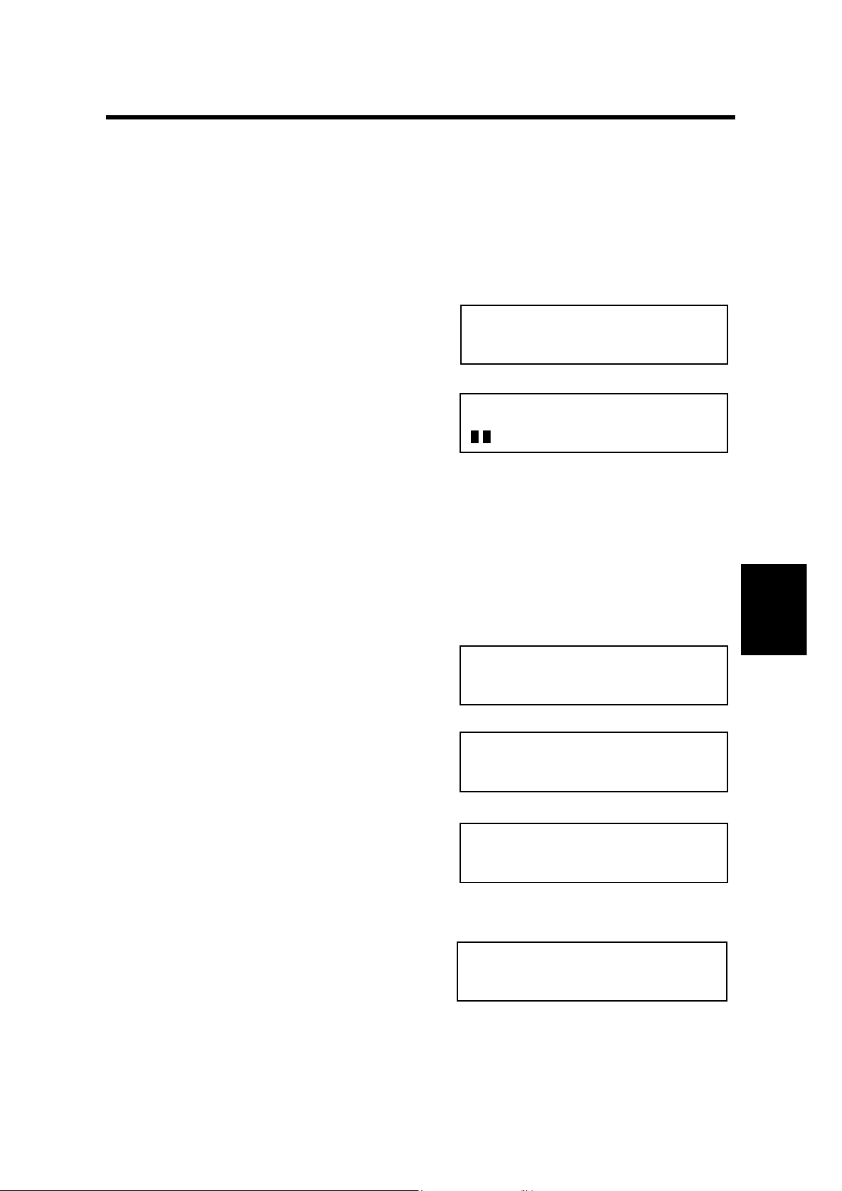
Example
[Service P-Mode] No._
1 Copy 2 Fax 3 Printer
B465S501.WMF
SERVICE FUNCTION
FUNCTION NO.
B465S502.WMF
SERVICE FUNCTION
01.BIT SW
B465S503.WMF
0.SYSTEM 1.SCANNER
2.PLOTTER 3.COMMUNI.
Tables
Service
1. Press '
2. Scroll through the bit switches.
To increment the bit switch number:
Press ‘→’
To decrement the bit switch number:
Press ‘←’
3. Adjust the bit switch.
Example: To change the value of bit 7,
press ,.
4. To adjust more bit switches, go to step
2.
To finish, press ‘OK’ then ‘CANCEL’.
5. Exit the service mode.
5-1
SYS DF :0000 0000
BITSW 00:0000 0000
B465S505
SYS DF :0000 0000
BITSW 00:1000 0000
B465S504.WMF
.WMF
B465S506.WMF
 Loading...