

Page 1

Model A-C2
PRINTER/SCANNER CONTROLLERS
(Machine Code: B361, B362)
SERVICE MANUAL
January 19th, 2001
Subject to change
Page 2

Trademarks
Microsoft®, Windows®, and MS-DOS® are registered trademarks of Microsoft
Corporation in the United States and /or other countries.
PostScript® is a registered trademark of Adobe Systems, Incorporated.
PCL® is a registered trademark of Hewlett-Packard Company.
Ethernet® is a registered trademark of Xerox Corporation.
Other product names used herein are for identification purposes only and may be
trademarks of their respective companies. We disclaim any and all rights involved
with those marks.
Page 3

TABLE OF CONTENTS
1 INSTALLATION ........................................................................... 1-1
1.1 INSTALLATION REQUIREMENTS...........................................................1-1
1.2 PRINTER INSTALLATION........................................................................1-1
1.3 POSTSCRIPT UNIT (G577)......................................................................1-7
1.4 MEMORY (G578/G579) ............................................................................1-8
1.5 NIB (G574)................................................................................................1-9
1.6 IEEE1394 INTERFACE (G590)...............................................................1-10
1.7 CHECKING THE CONNECTIONS..........................................................1-11
2 TROUBLESHOOTING ................................................................. 2-1
2.1 CONTROLLER ERRORS..........................................................................2-1
2.2 LEDS AND TEST POINTS........................................................................2-1
3 SERVICE TABLES....................................................................... 3-1
3.1 SERVICE PROGRAM MODE....................................................................3-1
3.1.1 ENABLING AND DISABLING SERVICE PROGRAM MODE...........3-1
3.2 PRINTER SERVICE MODE......................................................................3-2
3.2.1 SERVICE MODE TABLE..................................................................3-2
3.2.2 SP MODES RELATED TO PRINTER CONTROLLER.....................3-2
3.3 SCANNER SERVICE MODE.....................................................................3-3
3.3.1 SCANNER PROGRAM MODE TABLE.............................................3-3
3.4 FIRMWARE UPDATE PROCEDURE......................................................3-11
3.5 POWER-ON SELF TEST........................................................................3-11
3.6 SELF DIAGNOSTIC TEST......................................................................3-11
3.7 USER PROGRAM MODE.......................................................................3-12
3.7.1 PRINTER USER PROGRAM MODE..............................................3-12
3.7.2 SCANNER USER PROGRAM MODE............................................3-13
4 DETAILED SECTION DESCRIPTIONS ....................................... 4-1
4.1 OVERVIEW...............................................................................................4-1
4.2 CONTROLLER FUNCTIONS....................................................................4-2
4.2.1 SAMPLE PRINT...............................................................................4-2
4.2.2 LOCKED PRINT...............................................................................4-2
4.2.3 PAPER SOURCE SELECTION........................................................4-3
4.2.4 AUTO CONTINUE............................................................................4-4
4.2.5 PAPER OUTPUT TRAY...................................................................4-5
4.2.6 DUPLEX PRINTING......................................................................... 4-5
4.2.7 STAPLING ........................................................................................4-6
4.2.8 PUNCHING ......................................................................................4-6
4.3 SCANNER FUNCTIONS...........................................................................4-7
4.3.1 IMAGE PROCESSING FOR SCANNER MODE ..............................4-7
4.4 NIB ............................................................................................................4-8
4.4.1 BLOCK DIAGRAM............................................................................4-8
4.4.2 LED INDICATORS............................................................................4-8
4.5 IEEE1394 INTERFACE.............................................................................4-9
i
Page 4

4.5.1 SPECIFICATIONS............................................................................4-9
4.5.2 IEEE1394 .........................................................................................4-9
4.5.3 BLOCK DIAGRAM..........................................................................4-10
4.5.4 PIN ASSIGNMENT.........................................................................4-10
4.5.5 REMARKS ABOUT THIS INTERFACE KIT....................................4-11
4.5.6 TROUBLESHOOTING NOTES......................................................4-11
SPECIFICATIONS.....................................................................SPEC-1
1 GENERAL SPECIFICATIONS..............................................................SPEC-1
1.1 PRINTER.....................................................................................SPEC-1
1.2 SCANNER...................................................................................SPEC-3
2 SOFTWARE ACCESSORIES..............................................................SPEC-4
2.1 PRINTER.....................................................................................SPEC-4
2.2 SCANNER...................................................................................SPEC-5
3 MEACHINE CONFIGURATION............................................................SPEC-6
3.1 SYSTEM COMPONENTS...........................................................SPEC-6
ii
Page 5

19 January, 2001 INSTALLATION REQUIREMENTS
1. INSTALLATION
1.1 INSTALLATION REQUIREMENTS
Please refer to section 1 of the main unit service manual.
1.2 PRINTER INSTALLATION
Accessory Check
Check the accessories in the box against the following list:
No. Description Q’ty Note
1Cable 1
2 Paper Height Sensors 4
3 Edge Clamp 1
4 Cable Clamp 4
5 Paper Height Sensor Fe eler 2
6 Paper Sensor 1
7 Key Top - Printer 1
8 Key Top - Scanner 1 Included only in the B 362 (printer
and scanner) model
9 Paper Limit Sensor Unit 1
10 Tapping Screw - M3x8 2 To secure the paper limit sensor
unit
11 Pan Head Screw - M3x8 1 To secure the paper sensor
12 Installation Procedure 1
13 FCC Label 1 Included only in t he USA models.
Installation
1-1
Page 6
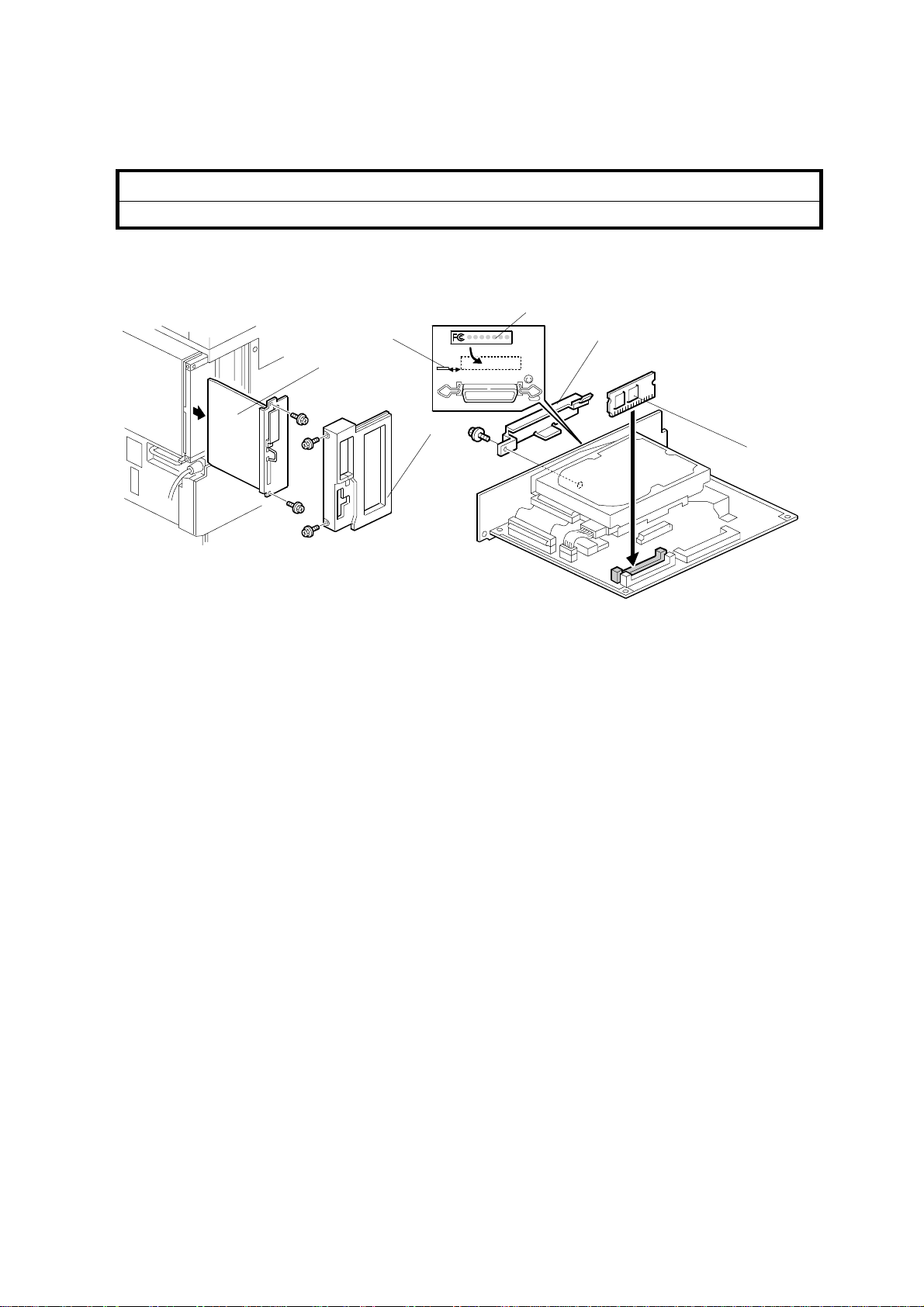
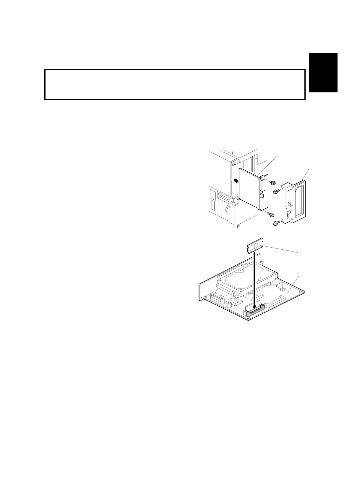
PRINTER INSTALLATION 19 January, 2001
Printer Controller Installation
!
CAUTION
Unplug the main machine power cord before starting the following procedure.
[E]
[F]
[D]
[B]
[A]
[C]
B361I101.WMF
B361I107.WMF
1. Remove the left rear cover [A] (2 screws) and slide out the controller board [B]
(2 screws).
2. Install the printer ROM DIMM [C] on the controller board.
3. Remove the parallel interface cover [D].
4. This step is required only in the USA models.
Attach the FCC label [E] on the controller panel board aligned with the slot [F]
so the label is hidden when the left rear cover is replaced.
NOTE: If the NIB (G574), Postscript kit (G577), memory board (G578/G579), or
IEEE1394 Interface (G590) are to be installed, remove the HDD and install
them before proceeding to the next step.
5. Put back the controller board and replace the left rear cover.
1-2
Page 7
19 January, 2001 PRINTER INSTALLATION
Paper Height Sensor Installation
[A]
[C]
[B]
B361I112.WMF
B361I113.WMF
Installation
[G]
[G]
[D]
[E]
[H]
[I]
[F]
B361I108.WMF
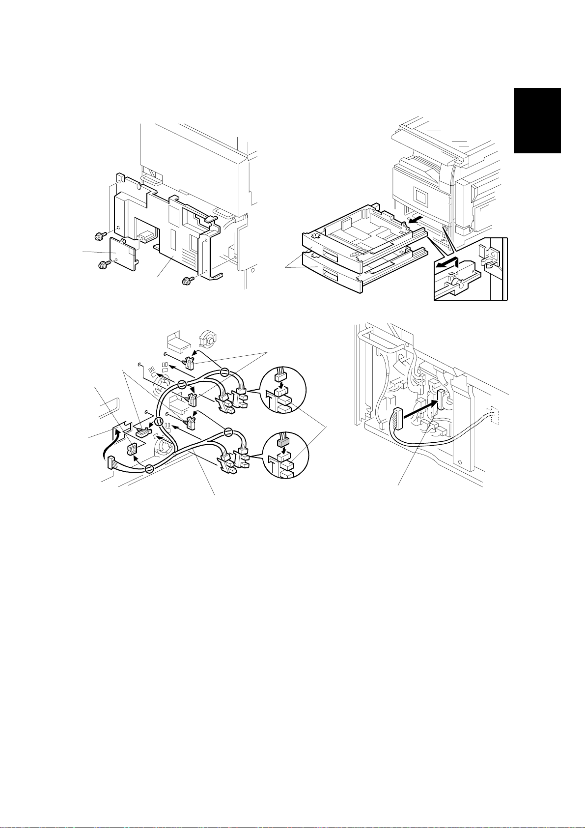
6. Remove the connector cover [A] and lower rear cover [B] (5 screws).
7. Pull out the two paper trays [C].
8. Install edge clamp [D] in the opening.
9. Connect the four paper height sensors [E] to the cable [F].
10. Install the four paper height sensors [E] as shown.
B361I109.WMF
11. Install the four cable clamps [G], then clamp the cable as shown.
12. Lead the cable through the opening [H]. Secure the cable in place with the
edge clamp attached in step 8.
13. Connect the cable to CN234 on the PCB [I].
1-3
Page 8
PRINTER INSTALLATION 19 January, 2001
[B]
[D]
[E]
[A]
B361I114.WMF
[F]
[C]
B361I115.WMF
[G]
B361I116.WMF
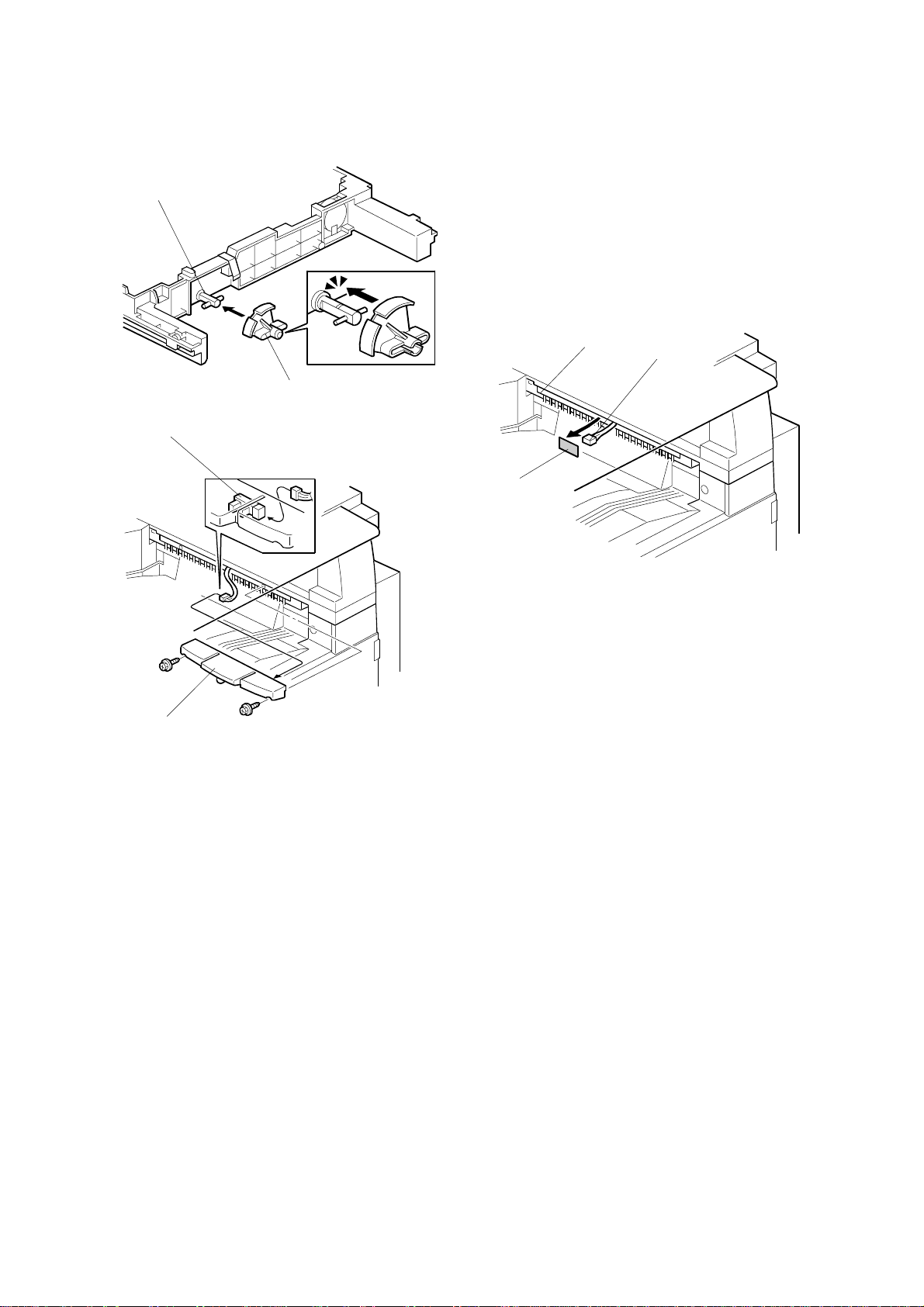
14. Install the paper height sensor feeler [A] on the bottom plate shaft [B] of each
paper tray.
15. Reassemble the machine.
Paper Limit Sensor Installation
If the optional bridge unit has been installed, skip steps 16 and 17.
16. Peel off the black tape [C] from the anti-static brush [D], then pull out the cable
[E].
17. Connect the cable to the sensor [F], then install the paper limit sensor unit [G]
(2 screws).
1-4
Page 9
19 January, 2001 PRINTER INSTALLATION
Paper Sensor Installation
[A]
[F]
[E]
[D]
[C]
[B]
Installation
B358I518.WMF
[G]
[H]
B358I517.WMF
B361I110.WMF
Perform steps 18 to 20 only if the optional bridge unit has been installed.
If it has not been installed, go on to step 21.
18. Remove the connector cover [A] and bridge unit [B] (2 screws, 2 connectors).
19. Open the right cover [C] of the bridge unit and peel off the black tape [D], then
pull out the connector [E].
20. Install the paper sensor [F] (1 screw, 1 connector) and reinstall the bridge unit.
Completion
21. Remove the bottom cap [G] of the operation panel. Install the Printer key [H]
on the operation panel as shown.
1-5
Page 10

PRINTER INSTALLATION 19 January, 2001
22. Do not connect the parallel cable at this point. Turn the machine on and check
the setting of the following copier SP mode:
• SP5-907: Plug & Play Name - select the correct one.
23. Print out the configuration page to check if the printer controller is installed
properly.
(Configuration page : User Tools/ Printer Settings/ List Test Print/ Config. Page)
24. If the parallel cable is going to be connected, first turn off the machine. After
connecting the cable, turn the machine back on.
1-6
Page 11
19 January, 2001 POSTSCRIPT UNIT (G577)
1.3 POSTSCRIPT UNIT (G577)
!
CAUTION
Unplug the main machine power cord before starting the following
procedure.
NOTE: To install the Postscript option, the printer option (B361) must be installed
first. Please refer to section 1.2 for detail s of the pri nter optio n inst all ati on
procedure.
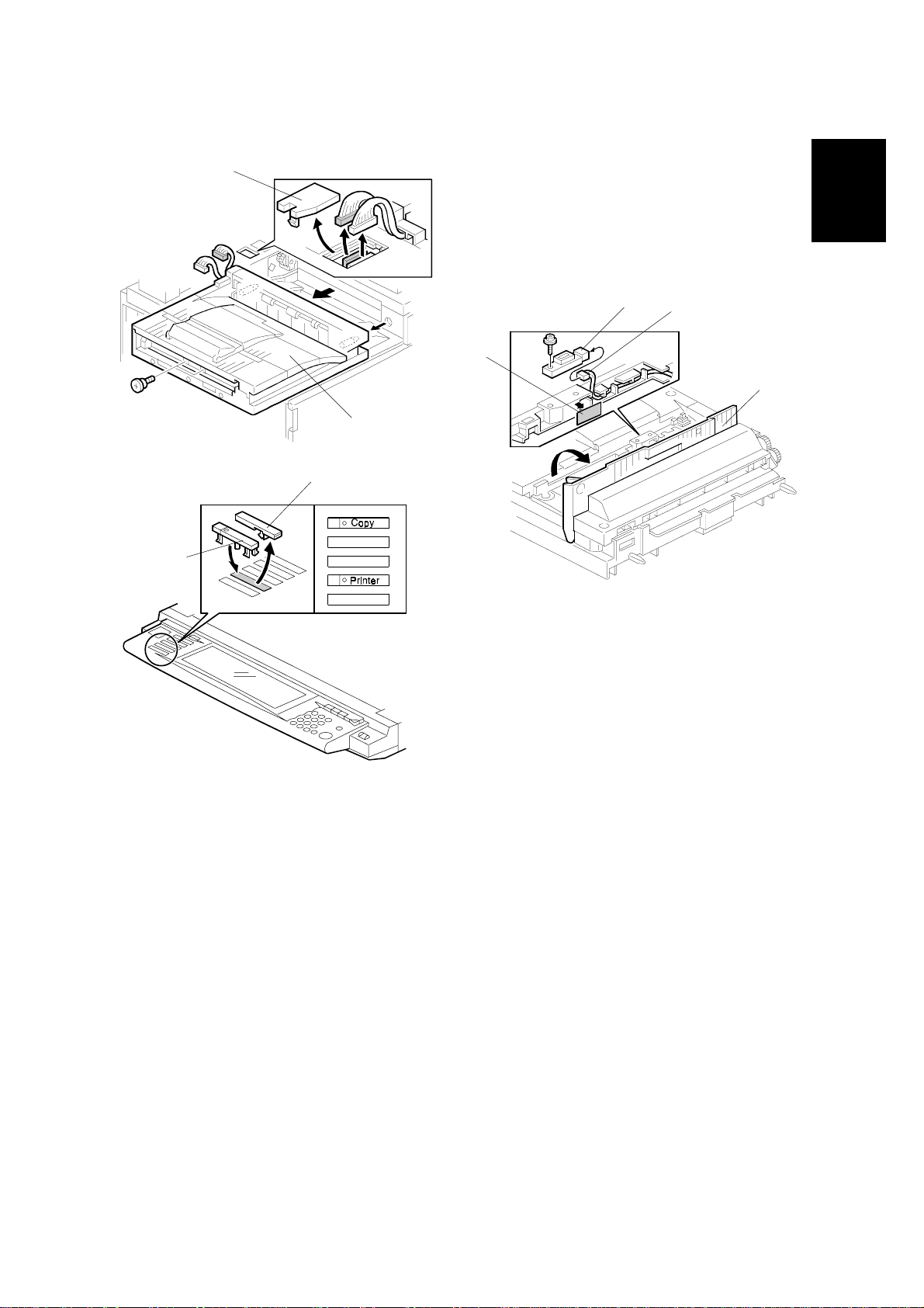
1. Remove the left rear cover [A] (2 screws).
[B]
Installation
2. Remove the controller board [B] (2 screws).
3. Install the Postscript DIMM [C] onto the
controller board [D].
4. Put back the controller board and replace
the left rear cover.
[A]
B361I101.WMF
[C]
[D]
B361I104.WMF
1-7
Page 12
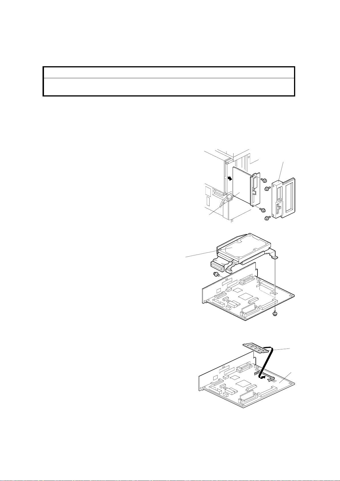
MEMORY (G578/G579) 19 January, 2001
1.4 MEMORY (G578/G579)
!
CAUTION
Unplug the main machine power cord before starting the following
procedure.
NOTE: To install the memory option, the printer option (B361) must be installed
first. Please refer to section 1.2 for detail s of the pri nter optio n inst all ati on
procedure.
1. Remove the left rear cover [A] (2 screws).
[A]
2. Remove the controller board [B] (2 screws).
3. Remove the HDD [C] (2 connectors,
3 screws).
4. Install the memory DIMM [D] onto the
controller board [E].
5. Re-install the HDD and put back the
controller board.
[B]
B361I101.WMF
[C]
B361I102.WMF
[D]
[E]
6. Replace the left rear cover.
B361I117.WMF
1-8
Page 13
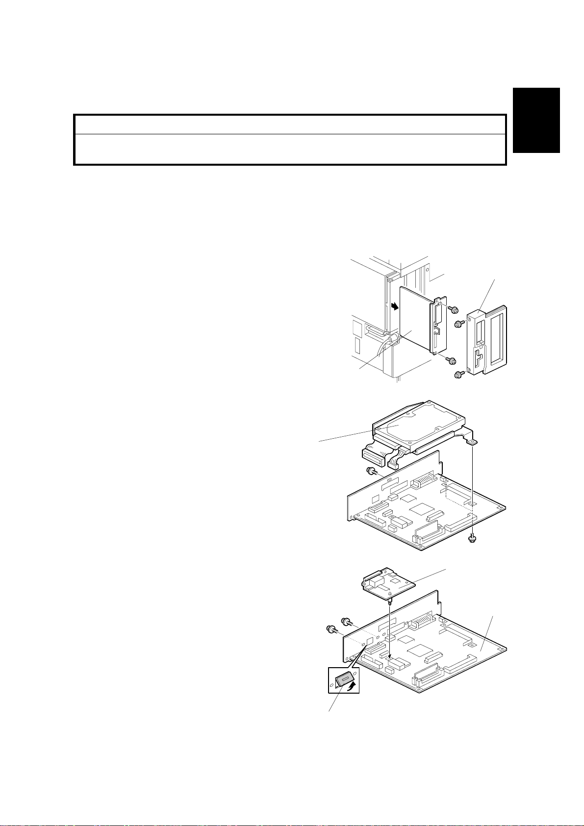
19 January, 2001 NIB (G574)
1.5 NIB (G574)
!
CAUTION
Unplug the main machine power cord before starting the following
procedure.
NOTE: To install the NIB option, the printer option (B361) must be installed first.
Please refer to section 1.2 for details of the printer option installation
procedure.
1. Remove the left rear cover [A] (2 screws).
[A]
2. Remove the controller board [B] (2 screws).
Installation
3. Remove the HDD [C] (2 connectors,
3 screws).
4. Remove the NIB slot cover [D].
5. Attach the NIB [E] to the controller board
[F] (2 screws).
[C]
[B]
[E]
B361I101.WMF
B361I102.WMF
[F]
6. Re-install the HDD and put back the
controller board.
7. Replace the left rear cover.
1-9
[D]
B361I105.WMF
Page 14
IEEE1394 INTERFACE (G590) 19 January, 2001
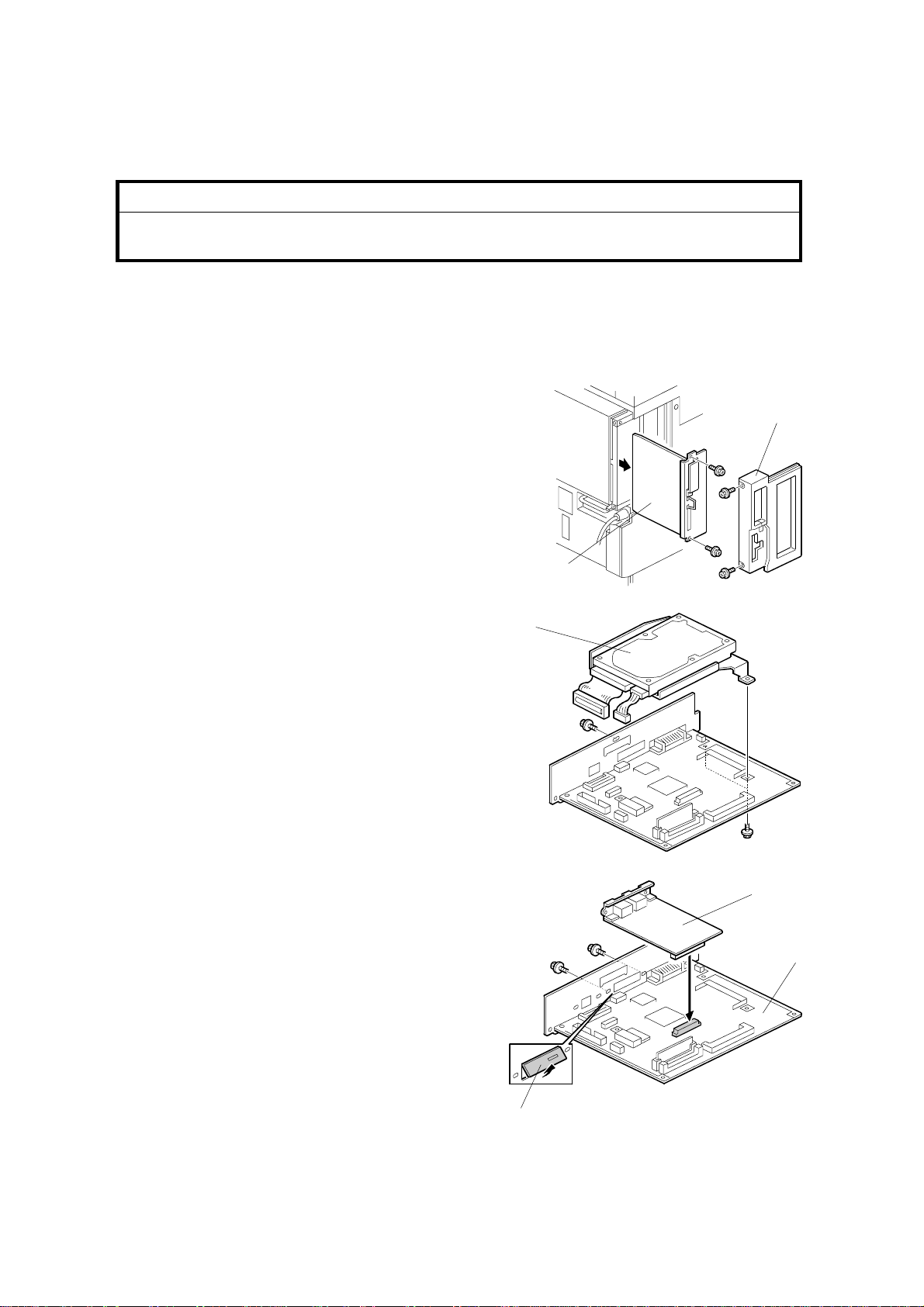
1.6 IEEE1394 INTERFACE (G590)
!
CAUTION
Unplug the main machine power cord before starting the following
procedure.
NOTE: To install the IEEE1394 option, the printer option (B361) must be installed
first. Please refer to section 1.2 for detail s of the pri nter optio n inst all ati on
procedure.
1. Remove the left rear cover [A] (2 screws).
[A]
2. Remove the controller board [B] (2 screws).
3. Remove the HDD [C] (2 connectors,
3 screws).
4. Remove the IEEE1394 cover [D].
5. Attach the IEEE1394 board [E] to the
controller board [F] (2 screws).
[B]
B361I101.WMF
[C]
B361I102.WMF
[E]
[F]
6. Re-install the HDD and put back the
controller board.
7. Remove the wire handle on the
controller panel board and place it on
the back side of the left rear cover.
8. Replace the left rear cover.
1-10
[D]
B361I106.WMF
Page 15

19 January, 2001 CHECKING THE CONNECTIONS
1.7 CHECKING THE CONNECTIONS
1. Plug in the power cord and turn on the main switch.
2. Enter the printer user mode and print the configuration page.
(User Tools/ Printer Settings/ List Test Print/ Config. Page)
The same data can also be printed using the printer service mode.
(“Print Summary”: SP1-004)
All installed options are listed in the “System Reference” column.
Installation
1-11
Page 16

19 January, 2001 CONTROLLER ERRORS
2. TROUBLESHOOTING
2.1 CONTROLLER ERRORS
Refer to section 4.1 of the main unit service manual for descriptions on SC code
information because the GW architecture includes controller SC codes in the main
unit SC code table.
2.2 LEDS AND TEST POINTS
LEDs and test points are not used for this option (except for the NIB ☛ section
4.4).
Trouble-
Shooting
2-1
Page 17

19 January, 2001 SERVICE PROGRAM MODE
3. SERVICE TABLES
3.1 SERVICE PROGRAM MODE
!
CAUTION
Before accessing the service menu, do the following:
Confirm that there is no print data in the printer buffe r (the Data In LED
must not be lit or blinking).
If there is some data in the buffer, wait until all data has been printed.
!
CAUTION
Never turn off the main power switch when the power LED is lit or flashing.
To avoid damaging the hard disk or memory, press the operation power
switch to switch the power off, wait for the power LED to go off, and then
switch the main power switch off.
NOTE: The main power LED ( ) lights or flashes while the platen cover or
ARDF is open, while the main unit is communicating with a facsimile or the
network server, or while the machine is accessing the hard disk or memory
for reading or writing data.
Tables
Service
3.1.1 ENABLING AND DISABLING SERVICE PROGRAM MODE
Entering the SP mode
"
#$%
&
Printer SP
Scanner SP
NOTE: If you switch the machine off, any jobs stored on the hard disk using the
sample print and protected print features will be deleted.
Check first if there are any jobs stored with these features
(Printer mode: View Sample Print Jobs/View Locked Print Job).
Exiting the Service Mode
Press “Exit” on the LCD panel to exit from the service mode.
1. Press the Clear Mode key.
2. Use the keypad to enter “107”.
3. Hold down Clear/Stop for at least 3 seconds.
4. Enter the Service Mode.
Press “Printer SP” to enter printer SP mode.
Press “Scanner SP” to enter scanner SP mode.
3-1
Page 18

PRINTER SERVICE MODE 19 January, 2000
3.2 PRINTER SERVICE MODE
3.2.1 SERVICE MODE TABLE
SP No. Description Function and Setting
1001 BitSw#1 Set Adjusts bit switch settings.
Note: Currently t he bit switches are not being used.
1003 Clear Setting Not used
1004 Print Summary
1005 Display Version Displays the version of the controller firmware.
3.2.2 SP MODES RELATED TO PRINTER CONTROLLER
The following SP modes are located in the copier SP mode. Refer to section 5.1 of
the main unit service manual.
Prints the service summary sheet
(An error log is printed in addition to the configuration
page).
SP No. Description Function and Setting
5104
5801
5907
7832
A3/DLT Double
Count
Memory All Clear
Plug & Play
Detailed Display of
Self-Diagnostics
Specifies whether the counter is doubled for A3/DLT.
0: No, 1: Yes
If # is selected, the total counter and t he current user
code counter count up twice when A3 or DLT paper is
used.
Resets data for process control an d all software counters,
and returns all modes and adjustments to their defaults
values.
☛ section 5.1.8 of the main unit manual for details.
Selects the brand name and the production name for
Windows Plug & Play. This information is stored in
NVRAM.
Displays the controller self-diagnostic result.
☛ section 3.6 of this manual f or det ails.
3-2
Page 19

19 January, 2001 SCANNER SERVICE MODE
3.3 SCANNER SERVICE MODE
3.3.1 SCANNER PROGRAM MODE TABLE
Service Table Key
Notation What it means
[range / default /
step]
italics Comments added for your reference.
*
DFU Denotes “Design or Factory Use”. Do not change this value.
SP1 Mode Number Function and [Setting]
1001
1002 Error Log Display Displays the error log data.
1003* FTP Port Number Changes the FTP port number.
1 Model Name Displays the model name.
2 Scanner Firmware
Version
3 Scanner Firmware
Number
4 Detail Model Na m e Displays the detail model name.
Example: [-9 ~ +9 / +3.0 / 0.1 mm step]. The set t ing can be
adjusted in the range ±9, value reset to +3.0 after an NVRAM
reset, and the value can be changed in 0.1 mm steps with each
key press.
This value is stored in NVRAM. After a RAM res et , t he defa ult
value (factory setting) is restored.
Displays the scanner fir mw are version.
Displays the firmware’s part number.
After changing this valu e, do the following:
Tables
Service
1. Run the Registry Editor
2. Access
/HKEY_LOCAL_MACHINE/SOFTWARE/
Ricoh/NetworkScanner
Change the value of ‘PortNo’ to this SP
3.
mode’s value
[0 – 65535 / 3670 / 1 step]
1004* Compression Type Selects the compression t ype for binary picture
processing.
[1: MH, 2: MR, 3: MMR]
1005* Erase Margin
1006* Auto Reset Timer Adjusts the auto reset timer for the scanner
Creates an erase margin for all edg es of the
scanned image.
If the machine has scanned the edge of the
original, create a margin.
[0 – 5 / 0mm / 1mm step]
function.
If this is “0”, the auto reset function is disabled.
[0, 10 – 99 / 60s / 1s step]
3-3
Page 20

SCANNER SERVICE MODE 19 January, 2000
SP2 Mode Number Function and [Setting]
2002
MTF Filter Coefficient
1*
(Text / Binary / Main scan)
2* MTF Filter Coefficient
(Text / Binary / Sub scan)
3* MTF Filter Strength
(Text / Binary / Main scan)
4* MTF Filter Strength
(Text / Binary / Sub scan)
5* Smoothing Filter
(Text / Binary)
6* Scanner Gamma
(Text / Binary)
7* Brightness – Notch 7
(Text / Binary)
8* Contrast – Notch 7
(Text / Binary)
9* Threshold Level – Notch 7
(Text / Binary)
10* Brightness – Notch 6
(Text / Binary)
11* Contrast – Notch 6
(Text / Binary)
12* Threshold Level – Notch 6
(Text / Binary)
13* Brightness – Notch 5
(Text / Binary)
Contrast – Notch 5
14*
(Text / Binary)
Threshold Level – Notch 5
15*
(Text / Binary)
Brightness – Notch 4
16*
(Text / Binary)
Contrast – Notch 4
17*
(Text / Binary)
Threshold Level – Notch 4
18*
(Text / Binary)
19* Brightness – Notch 3
(Text / Binary)
Selects the MTF filter coefficient in the main
scan direction for Text mode.
Select a higher number for a stronger filter.
If this is “0”, the MTF filter is not applied.
[0-15 / 7 / 1 step]
As above, for sub scan
[0-13 / 6 / 1 step]
Selects the MTF filter stren gt h in t he main scan
direction for Text mode.
Select a higher number for a stronger filter.
[0-7 / 5 / 1 step]
As above, for sub scan
[0-7 / 5 / 1 step]
Selects the smoothing pattern for Text mode
when using binary picture proce ssing mode.
A larger value could cause m oiré t o appear in
the image.
[0-7 / 0 / 1 step]
Selects the scanner gamma type for Text mode
when using binary picture proce ssing mode.
[0-6 / 4 / 1 step]
Adjusts the image densit y for each image
density level for Text mode when using binary
picture processing mode.
[0-255 / 128 / 1 step]
[0-255 / 128 / 1 step]
[0-255 / 160 / 1 step]
[0-255 / 128 / 1 step]
[0-255 / 128 / 1 step]
[0-255 / 145 / 1 step]
[0-255 / 128 / 1 step]
[0-255 / 128 / 1 step]
[0-255 / 135 / 1 step]
[0-255 / 128 / 1 step]
[0-255 / 128 / 1 step]
[0-255 / 128 / 1 step]
[0-255 / 128 / 1 step]
3-4
Page 21

19 January, 2001 SCANNER SERVICE MODE
SP2 Mode Number Function and [Setting]
2002
20* Contrast – Notch 3
(Text / Binary)
Adjusts the image densit y for each image
density level for Text mode when using binary
picture processing mode.
[0-255 / 128 / 1 step]
21* Threshold Level – Notch 3
(Text / Binary)
[0-255 / 100 / 1 step]
22* Brightness – Notch 2
(Text / Binary)
[0-255 / 128 / 1 step]
23* Contrast – Notch 2
(Text / Binary)
Threshold Level – Notch 2
24*
(Text / Binary)
Brightness – Notch 1
25*
(Text / Binary)
Contrast – Notch 1
26*
(Text / Binary)
Threshold Level – Notch 1
27*
(Text / Binary)
Independent Dot Erase
28*
(Text mode)
[0-255 / 128 / 1 step]
[0-255 / 85 / 1 step]
[0-255 / 128 / 1 step]
[0-255 / 128 / 1 step]
[0-255 / 70 / 1 step]
Selects the independent dot erase level.
With a larger SP setting, more dots are detect ed
as independent dots and erased.
If this is “0”, independent dot erase is disabled.
[0-7 / 4 / 1 step]
29* Unevenness correction
(Text mode)
Selects whether the unevenness correction is
done.
This function is like an F CI f unction. If this is “1”,
the edges of characters in scann ed images will
be smoothed.
[0: OFF, 1: ON]
2003
1* MTF Filter Coefficient
(Text/Photo / Binary /
Main scan)
Selects the MTF filter coefficient in the main
scan direction for Text/Photo mode.
Select a higher number for a stronger filter.
If this is “0”, the MTF filter is not applied.
[0-15 / 4 / 1 step]
MTF Filter Coefficient
28*
(Text/Photo / Binary / Sub
As above, for sub scan
[0-13 / 4 / 1 step]
scan)
3* MTF Filter Strength
(Text/Photo / Binary /
Main scan)
Selects the MTF filter stren gt h in t he main scan
direction for Text/Photo mode.
Select a higher number f or a stronger f ilt er.
[0-7 / 5 / 1 step]
4* MTF Filter Strength
(Text/Photo / Binary / Sub
As above, for sub scan
[0-7 / 5 / 1 step]
scan)
5* Smoothing Filter
(Text/Photo / Binary)
Selects the smoothing pattern for Text/Photo
mode when using binary picture pr ocessing
mode.
A larger value could cause m oiré t o appear in
the image.
[0-7 / 0 / 1 step]
Tables
Service
3-5
Page 22

SCANNER SERVICE MODE 19 January, 2000
SP2 Mode Number Function and [Setting]
2003
6* Scanner Gamma
(Text/Photo / Binary)
7* Brightness – Notch 7
(Text/Photo / Binary)
Contrast – Notch 7
8*
(Text/Photo / Binary)
Threshold Level – Notch 7
9*
(Text/Photo / Binary)
Brightness – Notch 6
10*
(Text/Photo / Binary)
11* Contrast – Notch 6
(Text/Photo / Binary)
12* Threshold Level – Notch 6
(Text/Photo / Binary)
13* Brightness – Notch 5
(Text/Photo / Binary)
14* Contrast – Notch 5
(Text/Photo / Binary)
15* Threshold Level – Notch 5
(Text/Photo / Binary)
16* Brightness – Notch 4
(Text/Photo / Binary)
17* Contrast – Notch 4
(Text/Photo / Binary)
18* Threshold Level – Notch 4
(Text/Photo / Binary)
19* Brightness – Notch 3
(Text/Photo / Binary)
20* Contrast – Notch 3
(Text/Photo / Binary)
Threshold Level – Notch 3
21*
(Text/Photo / Binary)
Brightness – Notch 2
22*
(Text/Photo / Binary)
Contrast – Notch 2
23*
(Text/Photo / Binary)
Threshold Level – Notch 2
24*
(Text/Photo / Binary)
Brightness – Notch 1
25*
(Text/Photo / Binary)
26* Contrast – Notch 1
(Text/Photo / Binary)
27* Threshold Level – Notch 1
(Text/Photo / Binary)
Selects the scanner gamma type for Text/Photo
mode when using binary picture pr ocessing
mode.
[0-6 / 5 / 1 step]
Adjusts the image densit y for each image
density level for Text/ Photo mode when using
binary picture processing mode.
[0-255 / 15 / 1 step]
[0-255 / 110 / 1 step]
This SP is not available.
[0-255 / 128 / 1 step]
[0-255 / 25 / 1 step]
[0-255 / 85 / 1 step]
This SP is not available.
[0-255 / 128 / 1 step]
[0-255 / 27 / 1 step]
[0-255 / 51 / 1 step]
This SP is not available.
[0-255 / 128 / 1 step]
[0-255 / 70 / 1 step]
[0-255 / 70 / 1 step]
This SP is not available.
[0-255 / 128 / 1 step]
[0-255 / 69 / 1 step]
[0-255 / 80 / 1 step]
This SP is not available.
[0-255 / 128 / 1 step]
[0-255 / 100 / 1 step]
[0-255 / 100 / 1 step]
This SP is not available.
[0-255 / 128 / 1 step]
[0-255 / 128 / 1 step]
[0-255 / 128 / 1 step]
This SP is not available.
[0-255 / 128 / 1 step]
3-6
Page 23

19 January, 2001 SCANNER SERVICE MODE
SP2 Mode Number Function and [Setting]
2004
1* MTF Filter Coefficient
(Photo / Binary / Main
scan)
Selects the MTF filter coefficient in the main
scan direction for Photo mode.
Select a higher number for a stronger filter.
If this is “0”, the MTF filter is not applied.
[0-15 / 0 / 1 step]
MTF Filter Coefficient
2*
(Photo / Binary / Sub
As above, for sub scan
[0-13 / 0 / 1 step]
scan)
3* MTF Filter Strength
(Photo / Binary / Main
scan)
Selects the MTF filter stren gt h in t he main scan
direction for Photo mode.
Select a higher number for a stronger filter.
[0-7 / 0 / 1 step]
MTF Filter Strength
4*
(Photo / Binary / Sub
As above, for sub scan
[0-7 / 0 / 1 step]
scan)
5* Smoothing Filter
(Photo / Binary)
Selects the smoothing pattern for Photo mode
when using binary picture proce ssing mode.
A larger value could cause m oiré t o appear in
the image.
[0-7 / 0 / 1 step]
6* Scanner Gamma
(Photo / Binary)
Selects the scanner gamma type for Photo
mode when using binary picture pr ocessing
mode.
[0-6 / 6 / 1 step]
Dither Matr ix Filter
7*
(Photo / Binary)
Selects the dither matrix ty pe for Photo mode
when using binary picture proce ssing mode.
[1-26 / 4 / 1 step]
8* Brightness – Notch 7
(Photo / Binary)
Adjusts the image densit y for each image
density level for Photo mode when using binary
picture processing mode.
[0-255 / 60 / 1 step]
9* Contrast – Notch 7
(Photo / Binary)
Threshold Level – Notch 7
10*
(Photo / Binary)
Brightness – Notch 6
11*
(Photo / Binary)
Contrast – Notch 6
12*
(Photo / Binary)
Threshold Level – Notch 6
13*
(Photo / Binary)
Brightness – Notch 5
14*
(Photo / Binary)
[0-255 / 128 / 1 step]
This SP is not available.
[0-255 / 128 / 1 step]
[0-255 / 100 / 1 step]
[0-255 / 128 / 1 step]
This SP is not available.
[0-255 / 128 / 1 step]
[0-255 / 120 / 1 step]
15* Contrast – Notch 5
(Photo / Binary)
16* Threshold Level – Notch 5
(Photo / Binary)
[0-255 / 120 / 1 step]
This SP is not available.
[0-255 / 128 / 1 step]
17* Brightness – Notch 4
(Photo / Binary)
[0-255 / 128 / 1 step]
Tables
Service
3-7
Page 24

SCANNER SERVICE MODE 19 January, 2000
SP2 Mode Number Function and [Setting]
2004
2005
18* Contrast – Notch 4
(Photo / Binary)
19* Threshold Level – Notch 4
(Photo / Binary)
20* Brightness – Notch 3
(Photo / Binary)
21* Contrast – Notch 3
(Photo / Binary)
Threshold Level – Notch 3
22*
(Photo / Binary)
Brightness – Notch 2
23*
(Photo / Binary)
Contrast – Notch 2
24*
(Photo / Binary)
Threshold Level – Notch 2
25*
(Photo / Binary)
Brightness – Notch 1
26*
(Photo / Binary)
27* Contrast – Notch 1
(Photo / Binary)
28* Threshold Level – Notch 1
(Photo / Binary)
1* MTF Filter Coefficient
(Grayscale / Main scan)
2* MTF Filter Coefficient
(Grayscale / Sub scan)
3* MTF Filter Strength
(Grayscale / Main scan)
MTF Filter Strength
4*
(Grayscale / Sub scan)
Smoothing Filter
5*
(Grayscale)
6* Scanner Gamma
(Grayscale)
Adjusts the image densit y for each image
density level for Photo mode when using binary
picture processing mode.
[0-255 / 128 / 1 step]
This SP is not available.
[0-255 / 128 / 1 step]
[0-255 / 135 / 1 step]
[0-255 / 135 / 1 step]
This SP is not available.
[0-255 / 128 / 1 step]
[0-255 / 138 / 1 step]
[0-255 / 133 / 1 step]
This SP is not available.
[0-255 / 128 / 1 step]
[0-255 / 140 / 1 step]
[0-255 / 133 / 1 step]
This SP is not available.
[0-255 / 128 / 1 step]
Selects the MTF filter coefficient in the main
scan direction when using graysca le processing
mode.
Select a higher number for a stronger filter.
If this is “0”, the MTF filter is not applied
[0-15 / 0 / 1 step]
As above, for sub scan
[0-13 / 0 / 1 step]
Selects the MTF filter stren gt h in t he main scan
direction when using grayscale processing
mode.
Select a higher number for a stronger filter.
[0-7 / 0 / 1 step]
As above, for sub scan
[0-7 / 0 / 1 step]
Selects the smoothing patt ern when using
grayscale processing mode.
A larger value could cause m oiré t o appear in
the image.
[0-7 / 0 / 1 step]
Selects the scanner gamma t ype when using
grayscale processing mode.
[0-6 / 3 / 1 step]
3-8
Page 25

19 January, 2001 SCANNER SERVICE MODE
SP2 Mode Number Function and [Setting]
2005
7* Brightness – Notch 7
(Grayscale)
Adjusts the image densit y for each image
density level when us ing the grayscale
processing mode.
[0-255 / 98 / 1 step]
8* Contrast – Notch 7
(Grayscale)
9* Threshold Level – Notch 7
(Grayscale)
[0-255 / 98 / 1 step]
This SP is not available.
[0-255 / 98 / 1 step]
10* Brightness – Notch 6
(Grayscale)
Contrast – Notch 6
11*
(Grayscale)
Threshold Level – Notch 6
12*
(Grayscale)
Brightness – Notch 5
13*
(Grayscale)
Contrast – Notch 5
14*
(Grayscale)
Threshold Level – Notch 5
15*
(Grayscale)
[0-255 / 108 / 1 step]
[0-255 / 108 / 1 step]
This SP is not available.
[0-255 / 108 / 1 step]
[0-255 / 118 / 1 step]
[0-255 / 118 / 1 step]
This SP is not available.
[0-255 / 118 / 1 step]
16* Brightness – Notch 4
(Grayscale)
[0-255 / 128 / 1 step]
17* Contrast – Notch 4
(Grayscale)
18* Threshold Level – Notch 4
(Grayscale)
[0-255 / 128 / 1 step]
This SP is not available.
[0-255 / 128 / 1 step]
19* Brightness – Notch 3
(Grayscale)
[0-255 / 138 / 1 step]
20* Contrast – Notch 3
(Grayscale)
21* Threshold Level – Notch 3
(Grayscale)
[0-255 / 138 / 1 step]
This SP is not available.
[0-255 / 138 / 1 step]
22* Brightness – Notch 2
(Grayscale)
[0-255 / 148 / 1 step]
23* Contrast – Notch 2
(Grayscale)
24* Threshold Level – Notch 2
(Grayscale)
[0-255 / 148 / 1 step]
This SP is not available.
[0-255 / 148 / 1 step]
25* Brightness – Notch 1
26*
27*
2006 1*
(Grayscale)
Contrast – Notch 1
(Grayscale)
Threshold Level – Notch 1
(Grayscale)
Compression Rat io
(Normal image)
[0-255 / 158 / 1 step]
[0-255 / 158 / 1 step]
This SP is not available.
[0-255 / 158 / 1 step]
Selects the compression ratio for grayscale
processing mode.
For a lower com p r es sion r at e , input a smaller
value.
[5-95 / 50 / 1 step]
Tables
Service
3-9
Page 26

SCANNER SERVICE MODE 19 January, 2000
SP2 Mode Number Function and [Setting]
2006
SP8 Mode Number Function and [Setting]
8001*
8002
8003* ECabinet IP Address
8004* Network Error Display
2* Compression Ratio
(High Quality imag e)
3* Compression Ratio
(Low Quality image)
Delivery Server IP
Address
1* Delivery Re-t r y
(Interval)
2* Delivery Re-t r y
(Number of re-try)
Time
[5-95 / 60 / 1 step]
[5-95 / 40 / 1 step]
Sets the IP address for the delivery server.
[000.000.000.000]
Sets the delivery re-try interval.
[60-999 / 300s / 1s step]
Sets the number of delivery re-t ries.
If this is “0”, the machine will not re-try to send
an image to the delivery serv er.
[0-99 / 3 times / 1 time step]
Sets the IP address for the eCabin et .
[000.000.000.000]
Selects the length of time that the network error
message for the scanner utilities is displayed.
If this is “0”, the error message is disp layed until
the error is solved.
[0-999 / 300 s / 1 s step]
SP9 Mode Number Function and [Setting]
9001
1Sysop
2Dapp
3Rapp
4Ui
5Nas
6Miw
7Djm
8Hpim
9mib
Bit switches for debugg ing. DFU
3-10
Page 27

19 January, 2001 FIRMWARE UPDATE PROCEDURE
3.4 FIRMWARE UPDATE PROCEDURE
Firmware updating procedure is described in section 5.2 of the main unit service
manual.
3.5 POWER-ON SELF TEST
The controller tests the following devices at power-on. If an error is detected, an
error code is stored in the controller board.
• CPU, ASIC and clock
• Flash ROM
• Resident and optional SDRAM
• Parallel interface
• NIB
• IEEE1394 interface (if installed)
• NVRAM
• HDD
Tables
Service
• Refer to section 4.1.2 of the main unit service manual for how to check the error
codes (SP 7-832).
3.6 SELF DIAGNOSTIC TEST
In addition to the power-on self test, you can set the machine in a more detailed
diagnostic mode to test other components and conditions.
It requires a loop-back connector (P/N: G0219350).
1. Turn off the machine and attach the loop-back connector to the parallel
interface.
2. Turn on the machine while pressing the “On Line” key and “# Enter” key
together.
3. The machine prints the diagnostic report automatically.
• Refer to section 4.1.2 of the main unit service manual for how to check the
error codes (SP 7-832).
3-11
Page 28

USER PROGRAM MODE 19 January, 2000
3.7 USER PROGRAM MODE
3.7.1 PRINTER USER PROGRAM MODE
Press the “Printer” key on the operation panel to enter the printer mode.
Press the “User Tools/Counter “, then select “Printer Settings” to change
printer settings.
User Mode Tree
Printer Mode
(Printer Key pressed)
User Tools/
Printer Settings
View Sample Print Jobs
View Locked Print Jobs
Paper Input
List/Test Print
System
Host Interface
PCL Menu
Bypass Size
Config. Sheet
Menu List
PCL Config. Page
PS Font List
Hex Dump
Panel LockingMaintenance
Misfeed Recovery
Print Error Report
Auto Continue
Memory Overflow
Job Separation (1-bin shift tray required)
Memory Usage
Duplex (optional duplex unit required)
Unit of Measure
Edge Smoothing
Resolution
Toner Saving
I/O Buffer
I/O Timeout
Orientation
Form Lines
Font Source
Font Number
Point Size
Font Pitch
Symbot Set
B362M501.WMF
3-12
Page 29

19 January, 2001 USER PROGRAM MODE
3.7.2 SCANNER USER PROGRAM MODE
Press the “User Tools/Counter “, then select “Scanner Settings” to change
scanner settings.
User Mode Tree
User Tools/
Scanner Features
Basic Settings
Scanner Settings
Subject Settings Program Change
Program Change
Delete
Initial Setup
Program 1 ~ 5
Function Priority
Delivery/Store Connection Time out
Compression (Black & White)
Compression (Grayscale)
Delivery Option
Original Setting
Original Orientation Priority
Mixed Originals Sizes Priority
SADF Auto Reset Timer
Delete
1 ~ 12
B361 M501.WMF
Tables
Service
3-13
Page 30

19 January, 2001 OVERVIEW
4. DETAILED SECTION DESCRIPTIONS
4.1 OVERVIEW
OPTION OPTION OPTION OPTION
IEEE1284 IC Card
HDD
Printer
(Scanner)
DIMM
PS3
RAM
(32/64 MB)
NIB
Flash ROM
(4 MB)
IEEE1394
IC Card I/F IDE Slot 1 Slot 2
Flash ROM DIMM (4/8 MB)
System
Flash ROM
(8 MB)
Resident
SDRAM
(32 MB)
SIMAC
PCI I/F
Mother Board
PCI I/F
BICU
CPU
SDRAM
DIMM
NVRAM
(32 kB)
Controller
B362D501.WMF
This machine uses the GW architecture. To enabl e the pr inter feat ur es, just install
the printer option ROM DIMM on the controller.
Detailed
Descriptions
Main components:
• CPU: QED RM5231
• SIMAC: G W architecture ASIC. It control s al l the functions of the controller
board.
• Flash ROM: 8MB Flash ROM for the system program
• SDRAM (resident): 32 MB SDRAM, expandable with 32 MB or 64 MB optional
SDRAM.
• NVRAM: Stores the controller settings
• HDD: Used to store additional soft fonts. Also used for collation, locked print,
sample print and form overlay
• IEEE 1284 interface
Optional components:
• PostScript3 DIMM
• Memory DIMM
• NIB
• IEEE1394 interface
4-1
Page 31

CONTROLLER FUNCTIONS 19 January, 2001
4.2 CONTROLLER FUNCTIONS
4.2.1 SAMPLE PRINT
This feature was formerly known as “Proof Print”. This function gives users a
chance to check the print results before starting a multiple-set print run.
• The size of the hard disk partition for the sample print feature is 5 GB. This
partition is also used by the collation and locked print features.
• The partition can hold up to 30 files, including files stored using locked print.
• The maximum number of pages is 2,000, including jobs using locked print and
collation.
4.2.2 LOCKED PRINT
Using this feature, the print job is stored in the machine but will not be printed until
the user inputs an ID at the machine’s operation panel. This ID must match the ID
that was input with the printer driver.
• Stored data is automatically deleted after it is printed.
• Stored data can be manually deleted at the operation panel.
• The hard disk can hold up to 30 files, including files stored using sample print.
• The maximum number of pages is 2,000, including jobs using sample print and
collation.
• Locked print uses the same hard disk partiti o n as sample print and collation,
which is 5 GB.
4-2
Page 32

19 January, 2001 CONTROLLER FUNCTIONS
4.2.3 PAPER SOURCE SELECTION
Tray Priority (Auto Tray Select)
The Tray Priority setting determines the start
of the tray search when the user selects
“Auto Tray Select” with the driver.
The machine searches for a paper tray with
the specified paper size and type.
When no tray contains paper that matches
the paper size and type specified by the
driver, the controller stops printing until the
user loads the correct paper.
Priority Tray
Tray 1
Tray 2
LCT (Optional)
Start of Tray Search
The Tray Priority setting can be specified
Tray 3 (Optional)
using the Paper Size Setting in the user tools.
(User Tools/ System Settings/ Paper Size
Tray 4 (Optional)
Settings)
B362D502.WMF
NOTE: The by-pass tray is not part of the tray search.
Tray Lock
If Tray Lock is enabled for a tray, the controller skips the “locked” tray in the tray
search process.
The Tray Lock setting can be specified by selecting “No” for the “Apply Auto Paper
Select” setting in the Paper Size Setting screen in the user tools.
(User Tools/ System Settings/ Paper Size Settings)
NOTE: The by-pass feeder cannot be locked.
Manual Tray Select
If the selected tray does not have the paper size and type specified by the driver,
the controller stops printing until the user loads the correct paper.
Detailed
Descriptions
4-3
Page 33

CONTROLLER FUNCTIONS 19 January, 2001
4.2.4 AUTO CONTINUE
When this function is ena bled, the ma chine stops pr inting and cancels the print job
if there is no paper tray which matches the paper size and paper type specified by
the driver.
If Auto Continue is enabled, the machine waits for a specified period (0, 1, 5, 10,
15 minutes) for the correct size paper to be set in the tray, then cancels the print
job if the interval expires.
• The interval can set with the Printer Settings in the user tools.
(User Tools/ Printer Settings/ System/ Auto Continue)
If Auto Continue is disabled, the machine will not print the job, but will not cancel it,
so the job stays in the print queue.
If no paper tray matches the paper size and paper type specified by the driver:
Auto Continue OFF
Immediately
1 minute
5 minute
10 minute
15 minute
NOTE: The default setting for Auto Continue is “Off.”
Job stays in the printer
Job is immediately canceled
Job is canceled after 1 minute
and so on
B362D512.WMF
4-4
Page 34

19 January, 2001 CONTROLLER FUNCTIONS
4.2.5 PAPER OUTPUT TRAY
The default paper output tray for each application (copy/fax/printer) can be
selected using the System Settings menu in the user tools.
(User Tools/ System Settings/ General Features)
If a print job does not specify an output tray or if the driver specifies the default tray,
the default paper output tray is used.
Output Tray Selected
• If an output tray is specified by the driver, it overrides the default tray setting in
the user tools.
• If the machine cannot print to the selected output tray, it prints to the default
paper output tray.
• If the mailbox unit is installed, paper larger than B4 cannot be printed to the
standard (internal) tray.
• If paper overflow is detected at the selected output tray, the controller stops
printing until the overflow detector goes off.
Sequential Stacking
When the nine-tray mailbox is s elected as the output tray and
“Printer Default” is specified as the output tray in the driver, the
machine automatically sends the output to the top tray (1st
tray). When that tray fills up, the machine sends the output to
the next tray.
This feature is called “Sequential Stacking.”
• If a tray becomes full and paper is detected in the next tray,
the machine displays an error and stops printing.
When paper in the next tray is removed, the machine
automatically resumes printing to the next tray.
• If all trays become full (overflow detected in all trays), the
machine displays an error and stops printing. This time, all
paper in all trays must be removed.
4.2.6 DUPLEX PRINTING
Top tray (1st tray)
2nd tray
3rd tray
4th, 5th, 6th, and so on
8th tray
Lowest tray (9th tray)
B362D509.WMF
Detailed
Descriptions
Duplex printing is available with all output bin options but not all paper sizes. If a
job specifies duplex printing but the paper size to be used cannot be used by the
duplex unit, the job will be printed single-sided.
• When the by-pass feeder is se lected as the paper source, duplex printing is
automatically disabled.
4-5
Page 35

CONTROLLER FUNCTIONS 19 January, 2001
4.2.7 STAPLING
Stapling is available when the two-tray (2250-sheet) finisher or 1000-sheet finisher
is installed.
The finishers have the following stapling positions.
1000 Finisher
Paper Feed Direction
(Printed side)
2 Tray Finisher
Stapled 2 places
Paper Feed Direction
(Printed side)
B362D510.WMF
• Depending on the paper orientation, the image may have to be rotated. The
image rotation is done by the controller.
• There is a limit for the number of sheets which can be stapled. If a job has more
than this number, it will not be stapled.
4.2.8 PUNCHING
Punching is available only when the punch kit is installed with the two-tray finisher.
The number of holes (2, 3, or 4 holes) depends on the type of punch kit.
• There is only one punch position available, so the relationship between the
punching position and the printed image depends on the paper feeding
orientation and image rotation.
2 Tray Finisher
Paper Feed Direction
(Printed side)
Punching Position
B362D511.WMF
4-6
Page 36

19 January, 2001 SCANNER FUNCTIONS
4.3 SCANNER FUNCTIONS
4.3.1 IMAGE PROCESSING FOR SCANNER MODE
The image processing for scanner mode is done in the IPU chip on the BICU
board. The IPU chip chooses the most suitable image processing methods
(gamma tables, dither patterns, etc) depending on the settings made in the driver.
The image compression method can be selected with SP mode (MR/MH/MMR for
binary picture processing, JPEG for grayscale processing).
Whether the user selects the image mode using the driver (TWAIN mode) or from
the operation panel (Delivery mode), the IPU chip does the image processing using
the appropriate image processing methods mentioned above.
Image Data Path
1. Image Store/Image Delivery Mode
Image
Scanning
Image
Processing
Image
Compression
BICU
HDD
NIB
ControllerSBU
File
Server
B361D500.WMF
The user can select the following modes from the LCD.
1) Delivery only
2) Store only
3) Store and delivery
After image processing and image compression, all image data for the job are
stored in the printer controller HDD us ing TIFF file format (binary picture
processing) or JPEG file format (grayscale processing). The type of TIFF format
used depends on the user’s scanner settings.
When delivery mode is selec ted, the controlle r creates a file which contains the
destination and page information, then the controller sends the file to a server.
Image
Scanning
Image
Processing
Compression
BICU
Image
NIB
ControllerSBU
Image
PC
B361D501.WMF
Detailed
Descriptions
2. Twain Mode
After image processing and image compression, the data (TIFF or JPEG) is sent
to the scanner Twain driver directory on the computer.
4-7
Page 37

NIB 19 January, 2001
4.4 NIB
4.4.1 BLOCK DIAGRAM
Flash ROM
4MB
LED
EEPROM
PHY
DP83846
Filter Module
RJ45
Network
Oscillator
NIB
B362D503.WMF
Controller
CN2
NIB I/F (CN12)
LED
• The Flash ROM contains the NIB firmware. The firmware can be upgraded using
an IC card connected to the controller board.
4.4.2 LED INDICATORS
LED2 (Yellow)
LED1 (Green)
B362D508.WMF
Description On Off
LED1 (Green): Link status Link success Link failure
LED2 (Yellow): Data rate 100 Mbps 10 Mbps
4-8
Page 38

19 January, 2001 IEEE1394 INTERFACE
4.5 IEEE1394 INTERFACE
4.5.1 SPECIFICATIONS
Hardware Specification
Interface: IEEE1394 (6 pins)
(no power supply, cable power repeated, IEEE1394a-2000 compliant)
Ports: 2 ports
Data rates: 400Mbps/200Mbps/100Mbps
System Requirements
PC: Windows PC with IEEE1394 port
OS: Microsoft Windows 2000 upgraded with service pack 1
Cable length: 4.5m (15ft)
4.5.2 IEEE1394
IEEE1394, also known as FireWire (a name patented by Apple), is an easy-to-use
peer-to-peer networking technology allowing speeds of up to 400 Mbps.
The current standard contains the following features, which are supported in most
devices:
Detailed
Descriptions
• Hot swapping (cables can be connected and disconnected while the
computer and other devices are switched on)
• Peer-to-peer networking (no hub required)
• No terminator or device ID is required, unlike SCSI
• Automatic configuration of devices upon start-up, or “plug and play.”
• Real-time data transfer at 100, 200, and 400 Mbps
• Common connecto rs for different devices
IEEE1394 I/F
IEEE1394 I/F
IEEE1394 Board
B362D506.WMF
B362V503.WMF
The cable length is limited to 4.5 m (15ft).
However, up to 16 cables and 63 devices can be connected to an IEEE1394
network.
IEEE1394 cables can be either 4-pin (data only) or 6-pin (data and power).
IEEE1394 allows either 6-pin or 4-pin connectors. However, this machine only uses
the 6-pin connectors. The machine has two 6-pin ports.
4-9
Page 39

IEEE1394 INTERFACE 19 January, 2001
4.5.3 BLOCK DIAGRAM
IEEE1394 Board
Oscillator
1394 I/F
PC
1394 I/F
TSB41AB2
• PHY: Physical layer control device
• Link: Link layer control device
• EEPROM: 256-byte ROM
4.5.4 PIN ASSIGNMENT
Pin 1
Clock
PHY
EEPROM
Link
TSB12LV23A
Controller
Option I/F (CN4)
B362D505.WMF
Pin assignment
Pin 1 Pin 4
Pin 2 Pin 3
Pin 5 Pin 6
Pin
No.
Signal Description
1Cable Power
2GND
3 Receive strobe
4 Transmit data
5 Receive data
6 Transmit strobe
Pin 6
B362D507.WMF
4-10
Page 40

19 January, 2001 IEEE1394 INTERFACE
4.5.5 REMARKS ABOUT THIS INTERFACE KIT
Note the following points about this unit.
• The machine does not print reports specifically for IEEE1394. Just print the
Configuration Page at installation to check that the machine recognizes the card.
• There is no spooler or print queue. If a computer tries to print over the IEEE1394
while the printer is busy, the IEEE1394 interface card inside the printer will return
a busy signal.
• After starting a job using IEEE1394, do not switch the printer off until the job has
been completed. Even though the printer may appear to be dead, it may be in
the middle of an IEEE1394 protocol exchange with the computer.
• When using IEEE1394, it is not possible to check the printer status from the
computer with a utility such as Printer Manager for Client.
4.5.6 TROUBLESHOOTING NOTES
If there are problems printing using the IEEE1394 interface, check the following.
• Is the computer using Windows 2000 with service pack 1?
• Has the interface card been replaced recently? Each card has an individual
address, similar to the MAC address in an Ethernet card. If the card was
changed, the driver cannot find the old card. The new card is another device and
a new printer appears in Windows Control panel, and this must be configured in
the same way as the printer that was replaced (the old printer icon in Windows
Control Panel should be deleted) has to be reconfigured.
• Is there a loop somewhere in the network? An IEEE1394 network must be a
chain or a branched chain. There can be no loops.
• Try to find out where in the chain the problem is occurring. Test the machine
one-to-one with the computer to determine if the printer is defective (when the
printer’s interface cable is plugged in, the computer should see ‘Printer Ready’;
when the cable is disconnected, the computer should see ‘Offline’).
Detailed
Descriptions
4-11
Page 41

19 January, 2001 SPECIFICATIONS
SPECIFICATIONS
1. GENERAL SPECIFICATIONS
1.1 PRINTER
Printing Speed: Maximum 45 ppm (A4/LT LEF): B004/B007 model
Maximum 35 ppm (A4/LT LEF): B003/B006 model
Printer Languages: PCL6/PCL5e
PostScript 3 (option)
RPCS (Refined Printing Command Stream) - an original
Ricoh PDL)
Resolution: 600 dpi (PCL 6/PCL5e/PS3/RPCS)
300 dpi (PCL5e/PS3)
Resident Fonts: PCL:
35 Intellifonts
10 True Type fonts
PS3:
136 fonts (24 Type 2 fonts, 112 Type 14 fonts)
Host Interfaces: Bi-directional IEEE1284 parallel x 1 (standard)
Ethernet (100 Base-TX/10 Base-T) (opt ion)
IEEE1394 (option)
Network Protocols:
Memory:
TCP/IP, IPX/SPX, NetBEUI, Apple Talk
Maximum 96 MB
(Standard 32 MB + 32 MB/64MB optional DIMM)
Spec.
Spec-1
Page 42

SPECIFICATIONS 19 January, 2000
Supported Paper Sizes
Paper Size (W x L)
Paper Trays
Main Unit/Option
By-pass
Tray
LCT Duplex
US Eur/Asia
A3 297 x 420 mm Y#/Y
B4 257 x 364 mm Y#/Y
#
#
Y/Y Y
#
Y#/Y
A4 SEF 210 x 297 mm Y/Y Y/Y Y
A4 LEF 297 x 210 mm Y/Y Y/Y Y
B5 SEF 182 x 257 mm Y#/Y
B5 LEF 257 x 182 mm Y#/Y
A5 SEF 148 x 210 mm Y#/Y
#
#
#
#
Y#/Y
#
Y#/Y
Y/Y Y
A5 LEF 210 x 148 mm N N Y
B6 SEF 128 x 182 mm N N Y
B6 LEF 182 x 128 mm N N N N N
A6 SEF 105 x 148 mm N N Y
Ledger 11 x 17” Y/Y Y#/Y
Legal 8.5 x 14“ Y/Y Y#/Y
#
#
Letter SEF 8.5 x 11” Y/Y Y/Y Y
Letter LEF 11 x 8.5” Y/Y Y/Y Y
Y#/Y
#
#
Half Letter SEF 5.5 x 8.5” Y/Y Y#/Y
Half Letter LEF 8.5 x 5.5” N N N N N
Executive SEF 7.25 x 10.5” Y#/Y
#
Executive LEF 10.5 x 7.25” N N Y
F 8 x 13” Y#/Y
Foolscap 8.5 x 13” Y#/Y
Folio 8.25 x 13” Y#/Y
#
#
#
Y#/Y
Y#/Y
Y#/Y
#
#
#
#
#
Y
#
#
#
Y
#
Y
#
#
C
C
#
Y
#
Y
#
#
#
Y
#
Y
#
#
Y
#
Y
#
Y
NY
NY
NY
YY
NY
NY
NY
NN
NN
NN
NY
NY
NY
YY
NY
NY
NY
NY
NY
NY
Com10 Env. 4.125 x 9.5” N N N N N
Monarch Env. 3.875 x 7.5” N N N N N
C6 Env. 114 x 162 mm N N N N N
C5 Env. 162 x 229 mm N N N N N
DL Env. 110 x 220 mm N N N N N
8K 267 x 390 mm Y#/Y
16K SEF 195 x 267 mm Y#/Y
16K LEF 267 x 195 mm Y#/Y
#
#
#
Y#/Y
Y#/Y
Y#/Y
#
#
#
#
Y
#
Y
#
Y
NY
NY
NY
Custom Minimum:
100 x 297 mm
Maximum:
NNY
C
NN
148 x 600 mm
Remarks:
Y Supported. The paper size sensor detects the paper size.
#
Y
C
Y
N Not supported.
Supported. The user has to select t he correct paper size for the tray.
Supported. The user has to enter the width and length of the paper.
Spec-2
Page 43

19 January, 2001 SPECIFICATIONS
1.2 SCANNER
Standard Scanner
Resolution:
Available scanning
Resolution Range:
Main scan/Sub scan
600 dpi
Twain Mode:
Book Mode (Main scan/Sub scan)
100 ~ 2400 dpi
ADF Mode (Main scan/Sub scan)
100 ~ 1200 dpi
Delivery Mode:
Book and ADF Mode (Main scan/Sub scan)
100 ~ 600 dpi
Grayscales: 8 bits/pixel
Scanning
Throughput:
25 spm for TWAIN
53 spm for Delivery mode
(A4L, ADF mode)
Interface: Ethernet (100 Base-TX/10 Base-T for TCP/IP)
Compression
Method:
Video Memory
Capacity:
MH, MR, MMR (Binary Picture Processing)
JPEG (Grayscale Processing)
8.3 MB (Twain)
24.9 MB (Delivery mode)
Image Storage
Capacity:
Number of originals per file: Maximum 160 pages
Maximum of files: 3000 files
Spec.
Spec-3
Page 44

SPECIFICATIONS 19 January, 2000
2. SOFTWARE ACCESSORIES
2.1 PRINTER
The printer drivers and utility software are provided on one CD-ROM. An auto-run
installer allows you to select which components to install.
PRINTER DRIVERS
Printer Langua ge
PCL 6 Yes Yes Yes No
PCL 5e Yes Yes Yes No
PS3 Yes Yes Yes Yes
RPCS Yes Yes Yes No
Windows
95/98/ME
Windows NT4.0 Windows 2000 Macintosh
NOTE: 1) The printer drivers for Windows NT 4.0 are only for the Intel x86
platform. There is no Windows NT 4.0 printer driver for the PowerPC,
Alpha, or MIPS platforms.
2) The PS3 drivers are all genuine AdobePS drivers, except for Windows
2000, which uses Microsoft PS. A PPD file for each operating system is
provided with the driver.
UTILITY SOFTWARE
Software Description
Agfa Font Manager
(Win 95/98/ME, NT4, 2000)
SmartNetMonitor for Admin
(Win 95/98/ME, NT4, 2000)
SmartNetMonitor for Client
(Win 95/98/ME, NT4, 2000)
1394 Utility (Win 2000)
DeskTopBinder V2 Lite
(Win 95/98/ME, NT4, 2000)
LAN-Fax M1
(Win 95/98/ME, NT4, 2000)
Address Book
(Win 95/98/ME, NT4, 2000)
Printer Utility for Mac
A font management utilit y with screen fonts for the printer.
A printer management util it y for network administrators. NIB
setup utilities are also available.
A printer management util it y for client users. Peer-to-peer
printing utility and parallel/recovery printing funct ions are
included.
A utility for removal IE EE 1394 printers.
A utility for document mana gement
PC LAN FAX driver
A utility for PC LAN FAX.
This software provides several convenient functions for printing
from Macintosh clients.
Spec-4
Page 45

19 January, 2001 SPECIFICATIONS
2.2 SCANNER
The scanner driver and utility software are provided on one CD-ROM.
SCANNER DRIVER
• Network Twain Driver for Win95/98/ME/NT3.51/NT4.0/2000
SCANNER UTILITIES
• Scan Router V2 Lite (Cherry-Lite) for Win95/98/ME/NT4.0/2000
• Desk Top Binder V2 Lite (Plumeri a- Li t e) for Win95/98/ME/NT4.0/2000
Spec.
Spec-5
Page 46

SPECIFICATIONS 19 January, 2000
3. MACHINE CONFIGURATION
3.1 SYSTEM COMPONENTS
Memory DIMM
5
7
Parallel I/FIC Card I/F
CPU
CN12
SIMAC
NVRAM
Controller Board
CN2
CN1
CN7 (SLOT1)
CN8 (SLOT2)
6
NIB
3
1
B362V502.WMF
2
4
IEEE1394 Board
Printer DIMM
or
Printer/
Scanner
DIMM
B362V501.WMF
PS3
DIMM
Item Machine Code No. Remarks
Printer Module
(ROM DIMM)
B362 1
Printer/Scanner
Module
B361 1
(ROM DIMM)
Option
Mailbox G909 6
Mailbox Bridge Unit G912 7
Internal Option
NIB G574 3
PostScript3 G577 2
Memory 64 MB G579
IEEE1394 G590 4
Spec-6
Used in common with the N AD and
Adonis-C1 (USA only).
Used in common with the mode l J
and K-P1.
 Loading...