

Page 1

Model A-C2 FAX UNIT
(Machine Code: B360)
SERVICE MANUAL
January 19th, 2001
Subject to change
Page 2

TABLE OF CONTENTS
1 INSTALLATION ........................................................................... 1-1
1.1 FAX UNIT..................................................................................................1-1
1.1.1 CAUTIONS.......................................................................................1-1
1.1.2 FLOW CHART..................................................................................1-2
1.1.3 FAX OPTION TYPE 1045 INSTALLATION ......................................1-3
1.1.4 G3 INTERFACE UNIT TYPE 1045 INSTALLATION.........................1-7
1.1.5 ISDN OPTION TYPE 1045 INST ALLATION ...................................1-11
2 TROUBLESHOOTING ................................................................. 2-1
2.1 ERROR CODES........................................................................................ 2-1
2.2 ERROR CODES FOR THE ISDN OPTION...............................................2-9
2.2.1 D-CHANNEL LAYER MANAGEMENT...........................................2-10
2.2.2 D-CHANNEL, LAYER 1..................................................................2-10
2.2.3 D-CHANNEL LINK LAYER.............................................................2-10
2.2.4 D-CHANNEL NETWORK LAYER...................................................2-11
2.2.5 B-CHANNEL LINK LAYER.............................................................2-11
2.2.6 B-CHANNEL NETWORK LAYER...................................................2-12
2.2.7 TRANSPORT LAYER.....................................................................2-12
2.2.8 SESSION LAYER...........................................................................2-13
2.2.9 DOCUMENT LAYER......................................................................2-14
2.2.10 PRESENTATION LAYER.............................................................2-14
2.3 FAX SC CODES......................................................................................2-15
2.3.1 OVERVIEW....................................................................................2-15
2.3.2 SC1201........................................................................................... 2-15
2.3.3 SC1207........................................................................................... 2-15
2.3.4 FAX SC CODE TABLE...................................................................2-16
2.4 ISDN TEST FUNCTION ..........................................................................2-17
2.4.1 LEDS..............................................................................................2-17
2.4.2 BACK-TO-BACK TEST...................................................................2-18
3 SERVICE TABLES....................................................................... 3-1
3.1 SERVICE PROGRAM MODE....................................................................3-1
3.1.1 SERVICE PROGRAM MODE OPERAT ION.....................................3-1
3.1.2 SERVICE PROGRAM MODE TABLES............................................3-4
3.2 BIT SWITCHES.......................................................................................3-10
3.2.1 SYSTEM SWITCHES.....................................................................3-10
3.2.2 SCANNER SWITCHES..................................................................3-22
3.2.3 PRINTER SWITCHES....................................................................3-27
3.2.4 COMMUNICATION SWITCHES.....................................................3-32
3.2.5 G3 SWITCHES...............................................................................3-41
3.2.6 G3-2 SWITCHES............................................................................3-49
3.2.7 G3-3 SWITCHES............................................................................3-54
3.2.8 G4 INTERNAL SWITCHES............................................................3-55
3.2.9 G4 PARAMETER SWITCHES........................................................3-62
3.3 NCU PARAMETERS...............................................................................3-65
i
Page 3

3.4 DEDICATED TRANSMISSION PARAMETERS......................................3-76
3.4.1 PROGRAMMING PROCEDURE....................................................3-76
3.4.2 PARAMETERS...............................................................................3-77
3.5 SERVICE RAM ADDRESSES.................................................................3-81
DETAILED SECTION DESCRIPTIONS ........................................... 4-1
4.1 OVERVIEW...............................................................................................4-1
4.2 BOARDS...................................................................................................4-2
4.2.1 FCU..................................................................................................4-2
4.2.2 NCU (US) .........................................................................................4-4
4.2.3 NCU (EUROPE/ASIA)......................................................................4-5
4.2.4 SG3 BOARD.....................................................................................4-6
4.2.5 SIG4 BOARD....................................................................................4-7
4.3 VIDEO DATA PATH..................................................................................4-8
4.3.1 TRANSMISSION..............................................................................4-8
4.3.2 RECEPTION...................................................................................4-11
4.4 FAX COMMUNICATION FEATURES .....................................................4-13
4.4.1 PERSONAL/INFORMATION/TRANSFER BOXES.........................4-13
4.4.2 MULTI-PORT..................................................................................4-16
4.4.3 DOCUMENT SERVER...................................................................4-17
4.4.4 LAN FAX DRIVER..........................................................................4-18
SPECIFICATIONS.....................................................................SPEC-1
1 GENERAL SPECIFICATIONS..............................................................SPEC-1
2 CAPABILITIES OF PROGRAMMABLE ITEMS....................................SPEC-3
3 MACHINE CONFIGURATION..............................................................SPEC-4
ii
Page 4

19 January, 2001 FAX UNIT
1. INSTALLATION
1.1 FAX UNIT
1.1.1 CAUTIONS
NOTE: 1) Never install telephone wiring during a lightning storm.
2) Never install telephone jacks in wet locations unless the jack is
specifically designed for wet locations.
3) Never touch uninsulated telephone wires or terminals unless the
telephone line has been disconnected at the network interface.
4) Use caution when installing or modifying telephone lines.
5) Avoid using a telephone (other than a cordless type) during an electrical
storm. There may be a remote risk of electric shock from lightning.
6) If there is a gas leak, do not use the telephone in the vicinity of the leak
to report it.
!
CAUTION
1. Before installing the fax unit, switch off the main power and operation
switches, and disconnect the power cord.
2. The fax unit contains a lithium battery. The danger of explosion exists if
a battery of this type is incorrectly replaced. Replace only with the same
or an equivalent type recommended by the manufacturer. Discard used
batteries in accordance with the manufacturer’s instructions.
Installation
1-1
Page 5
FAX UNIT 19 January, 2001
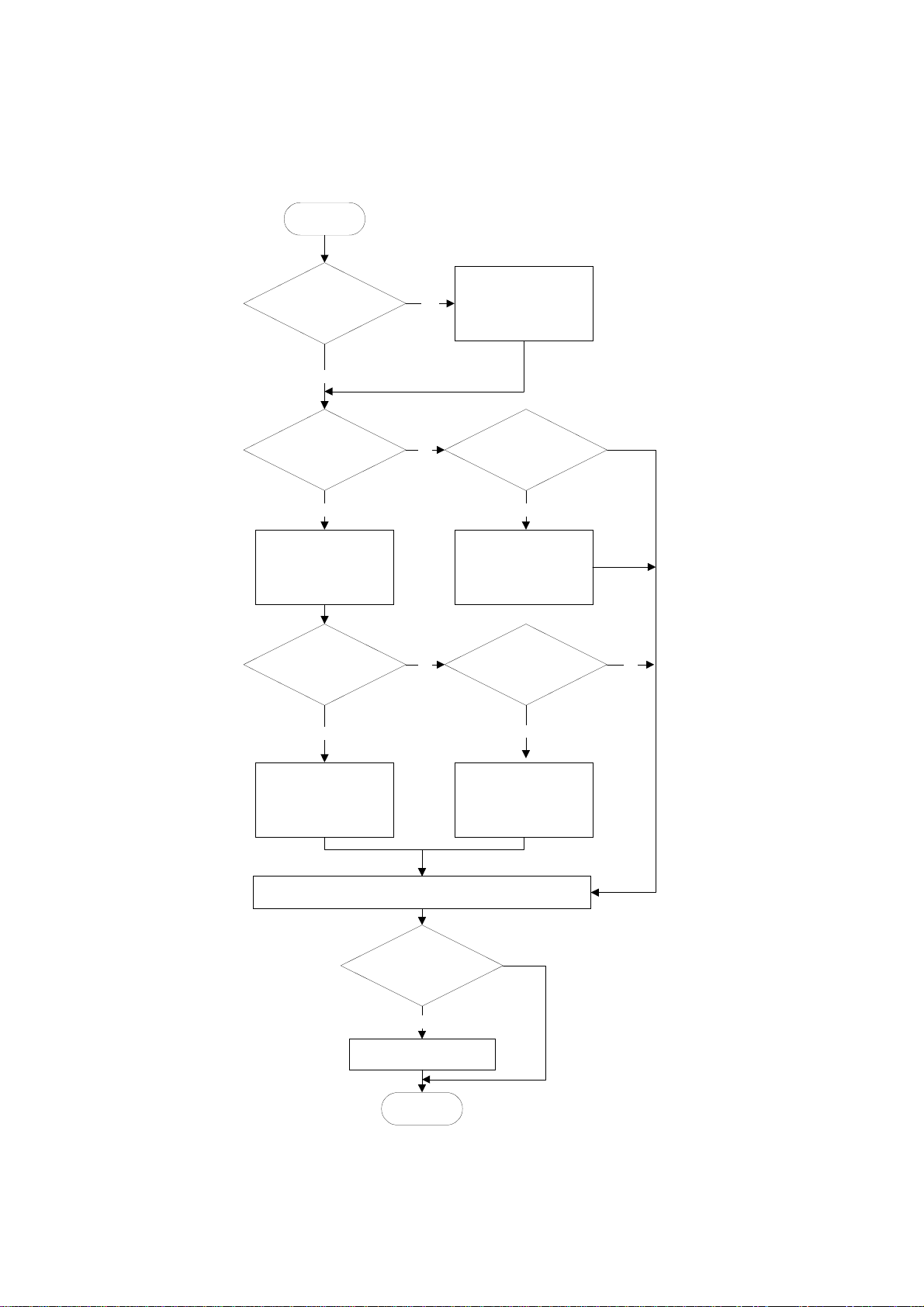
1.1.2 FLOW CHART
Before installing the fax unit and/or fax options, refer to the following flow chart.
START
Will y o u be ins ta llin g th e F a x
Function Upgrade Unit and/or
Expansion Me m ory?
No
Will y o u be ins ta llin g th e G3
Interfa c e U n it (C H 1 )?
Yes
Install the CCUIF board and
optin G3 board to the FCU
board. (Downside connector on
the CCUIF board)
Attach the option NCU board
to the NCU unit. (Downside of
the NCU unit).
Will y o u be ins ta llin g th e G3
Interfa c e U n it (C H 2 )?
Yes
Install the Fax Function Upgrade
Yes
Unit and/or Expansion Mem ory
to the FCU board.
Will y o u be ins ta llin g th e ISDN
No
Install the CCUIF board and
optin ISDN board to the FCU
board. (Upside connector on the
CCUIF board)
Remove the s m all plate of the
FCU cover.
Will y o u be ins ta llin g th e ISDN
No
Option?
Yes
Option?
Yes
No
No
Install the CCUIF board and
optin G3 board to the FCU
board. (Upside connector on the
CCUIF board)
Attach the option NCU board
to the NCU unit. (Upside of the
NCU unit).
Insert the FCU baord to the machine and attach the N C U u nit to the machiene.
Reaasemble the operation panel and affix the decals.
Will y o u be ins ta llin g th e
handset?
* USA model only
Yes
Install the handset.
END
Install the optin ISDN board to
the FCU board. (Upside
connector on the CCUIF bo ard)
Remove the s m all plate of the
FCU cover.
No
B360I501.WMF
1-2
Page 6
19 January, 2001 FAX UNIT
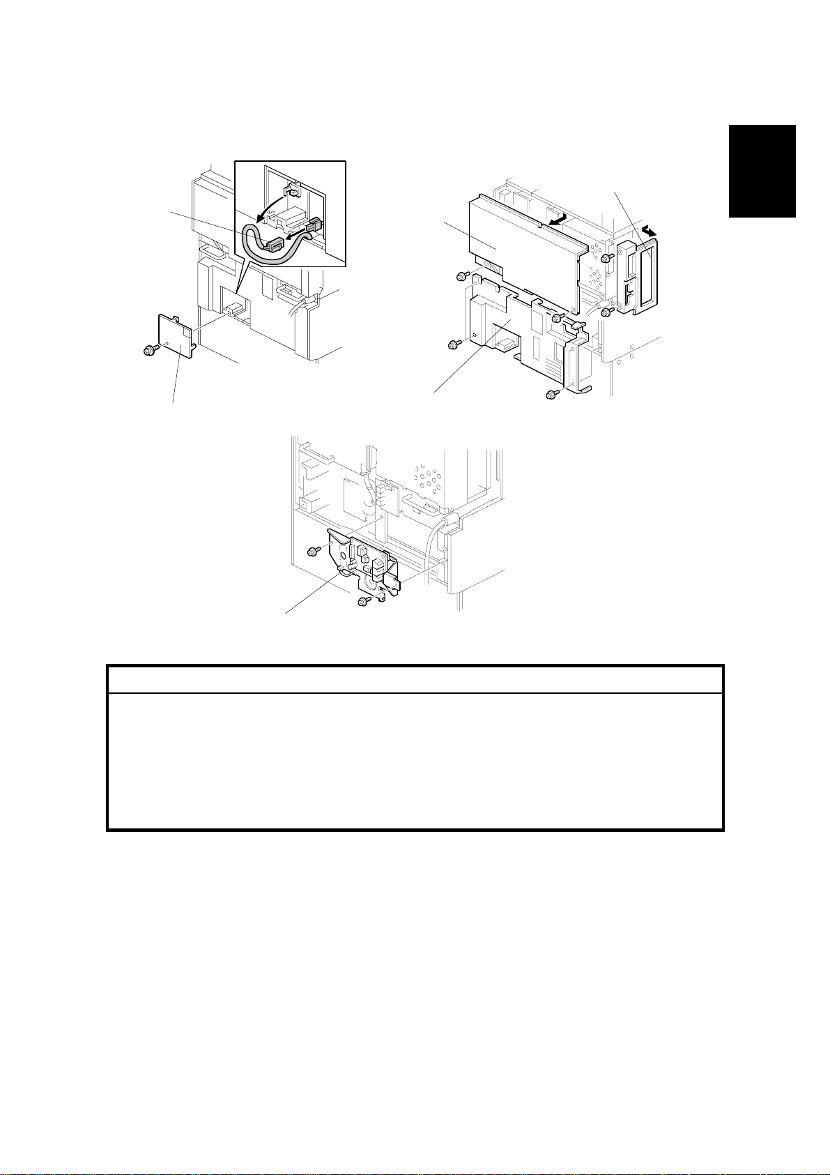
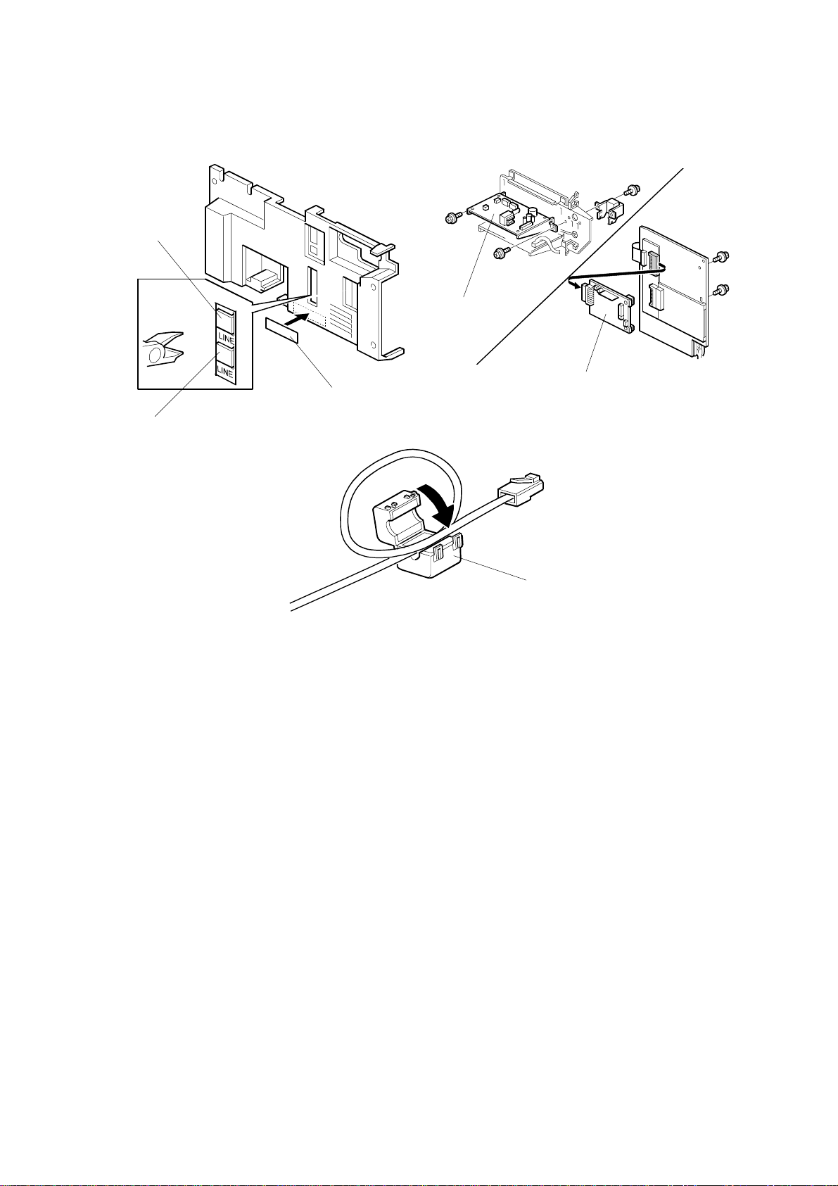
1.1.3 FAX OPTION TYPE 1045 INSTALLATION
[B]
[A]
B360I101.WMF
[D]
[E]
[C]
B360I102.WMF
Installation
[F]
B360I103.WMF
!
CAUTION
Before installing this option, do the following:
1. If there is a printer option in the machine, print out all data in the printer
buffer.
2. Press the operation switch to enter standby mode. Make sure the power
LED is not lit, then turn off the main switch and disconnect the power
cord and the network cable.
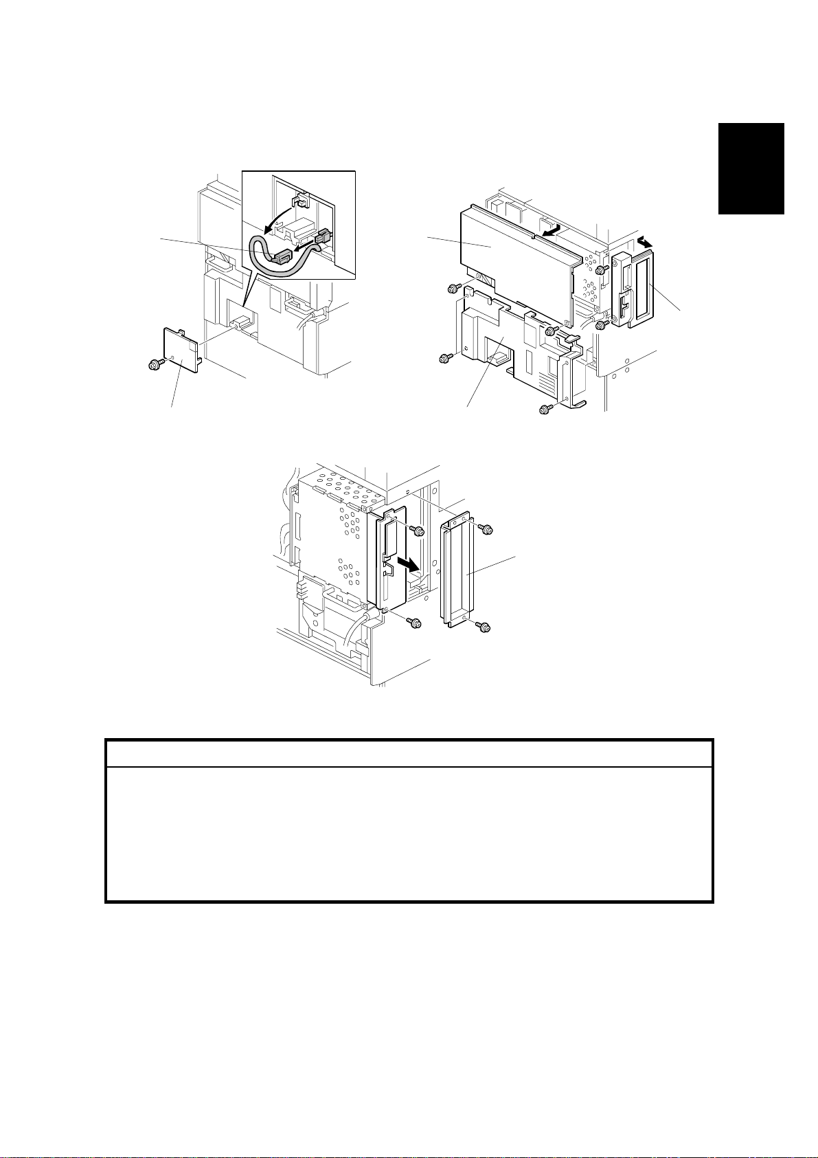
1. Remove the small cover [A] (1 screw) and connector [B].
2. Remove the left rear cover [C] (2 screws), the rear upper cover [D] (2 screws)
and the rear lower cover [E] (4 screws).
3. Attach the NCU unit [F] to the machine (2 screws).
NOTE: If any G3 Interface Unit Type 1045 has to been installed, attach the
additional NCU boards to the NCU unit before attaching the NCU unit
to the machine. Refer to the Installation Procedure for the G3 Interface
Unit Type 1045.
1-3
Page 7
FAX UNIT 19 January, 2001
[B]
[D]
[C]
B360I105.WMF
[A]
B360I104.WMF
[F]
[E]
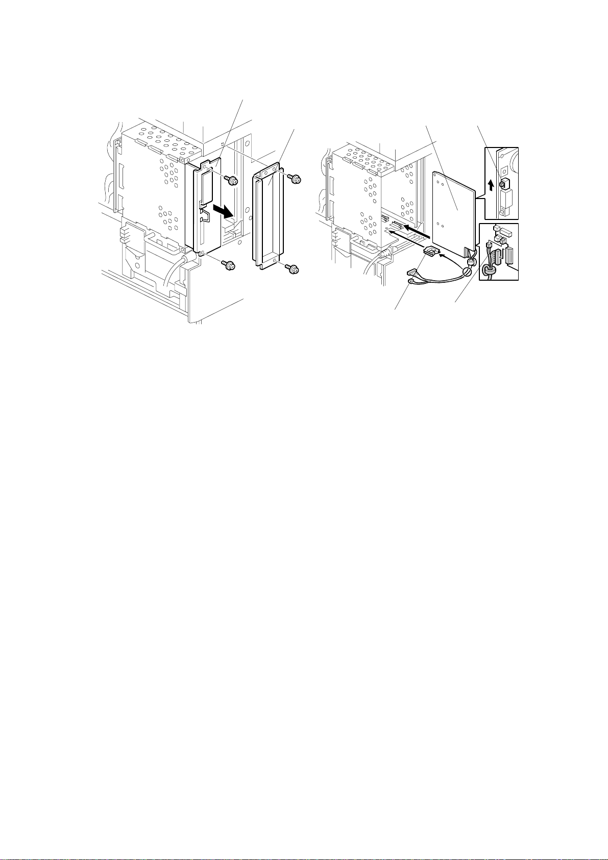
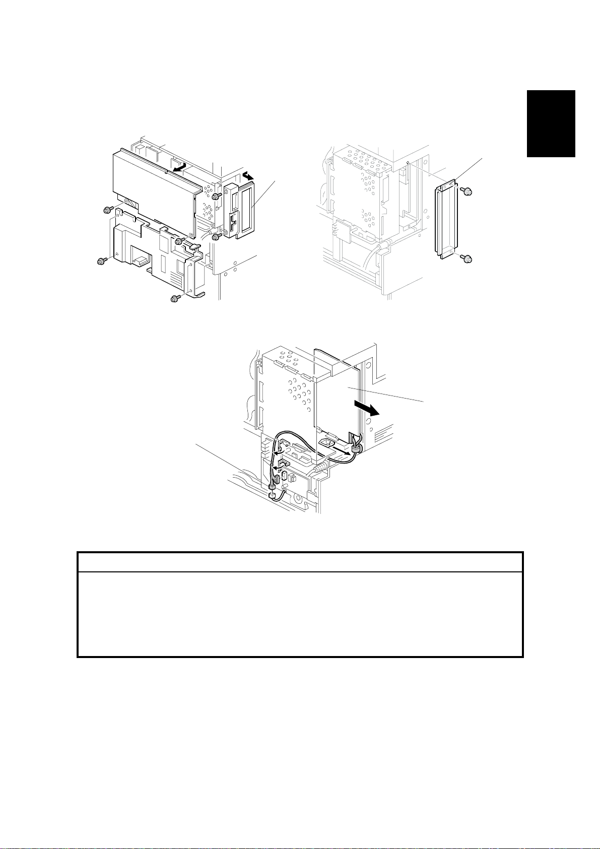
4. Remove the FCU cover [A] (2 screws) and the controller unit [B] (2 screws).
5. Turn on the battery switch (SW1) [C] on the FCU board [F], connect the
harness [D] to the FCU board. Then slide the FCU board into the right slot of
the expansion box.
NOTE: If any following options will be installed at the same time, connect the
option board to the FCU board before sliding the FCU board into the
expansion box. Refer to the Installation Procedure of each option.
• Fax Function Upgrade Type 185
• G3 Interface Unit Type 1045
• ISDN option T ype 1045
6. Attach the edge clamp [E] to the bottom of the expansion box, then clamp the
FCU harness [D].
7. Machine Codes B003 and B004: Attach the DIMM board (4MB) to slot 1
(CN7) on the controller board.
Machine Codes B006 and B007: You don’t have to attach the DIMM board to
the controller board. The 8MB DIMM board is already installed on the controller
board of these models.
1-4
Page 8
19 January, 2001 FAX UNIT
[A]
[B]
[I]
B360I106.WMF
[C]
[E]
[D]
[F]
Installation
[G]
[H]
B360I107.WMF
[J]
B366I107.WMF
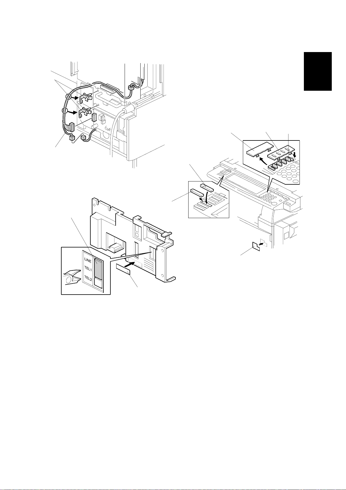
8. Attach the harness clamps [A] and connect the FCU harness [B] to the NCU
board. Then clamp the ha rness as shown.
9. Reattach the FCU cover and the controller unit.
NOTE: If the ISDN option is installed, cut away the small part from the FCU
cover for the ISDN connector. Refer to the Installation Procedure for
the ISDN Option Type 1045.
10. Remove parts [C] and [D], then install parts [E], [F] and [G]. Attach the super
G3 decal [H] to the front cover as shown.
11. Cut away the telephone connector cover [I]. Attach the FCC decal and the
serial number decal [J] to the rear cover as shown.
12. Reattach the covers.
1-5
Page 9
FAX UNIT 19 January, 2001
[A]
B360I108.WMF
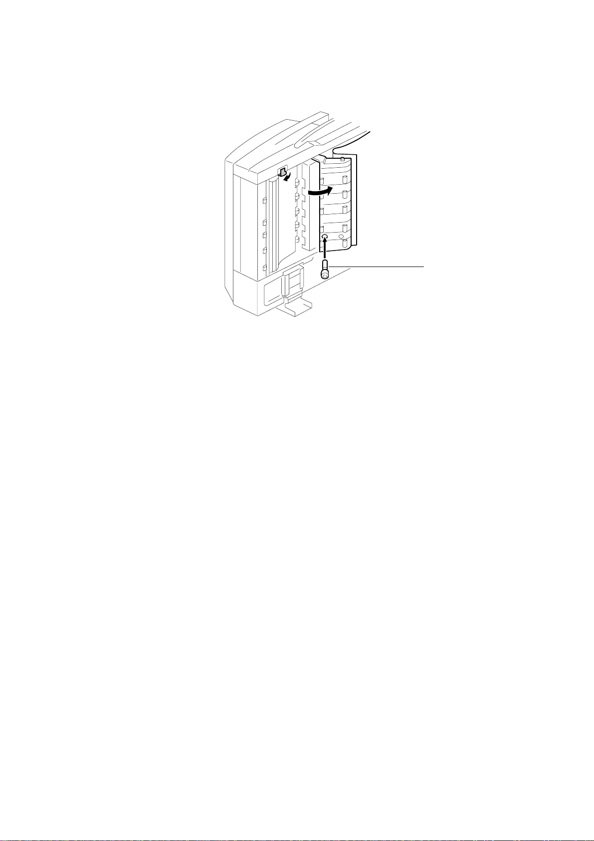
13. If the ADF has been installed, insert the stamp cartridge [A] into the ADF as
shown.
14. Connect the telephone line to the “LINE” jack at the rear of the machine.
15. Plug in the machine and turn on the main power switch.
16. Be sure to set the clock (date and time).
17. Enter service mode and program the serial number into the fax unit (SP-3-102-
000). The serial number can be found on the serial number label (attached to
the machine in step 11).
1-6
Page 10
19 January, 2001 FAX UNIT
1.1.4 G3 INTERFACE UNIT TYPE 1045 INSTALLATION
Installation
[B]
[A]
[D]
[C]
B360I101.WMF
[E]
B360I102.WMF
[F]
B360I104.WMF
!
CAUTION
Before installing this option, do the following:
1. If there is a printer option in the machine, print out all data in the printer
buffer.
2. Press the operation switch to enter standby mode. Make sure the power
LED is not lit, then turn off the main switch and disconnect the power
cord and the network cable.
1. Remove the small cover [A] (1 screw) and the connector [B].
2. Remove the rear cover [C] (2 screws), the rear upper cover [D] (2 screws) and
the rear lower cover [E] (4 screws).
3. Remove the FCU cover [F] (2 screws) and controller unit (2 screws).
1-7
Page 11
FAX UNIT 19 January, 2001
[F]
[D]
[E]
[C]
[B]
B366I101.WMF
[A]
[G]
B366I109.WMF
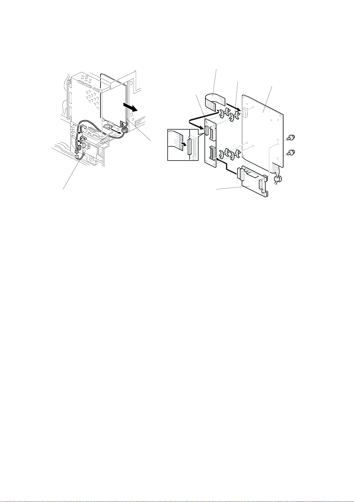
4. Remove the FCU harness [A] and slide out the FCU board [B] from the
machine.
5. Attach the four locking supports [D] to the CCUIF board [C]. Then attach the
CCUIF board to the FCU board [E] as shown.
6. Attach the flat cable [F] to the FCU board and the CCUIF board.
7. Attach the option G3 board [G] to the lower connector of the CCUIF board (2
screws).
1-8
Page 12
19 January, 2001 FAX UNIT
[C]
Installation
[A]
[F]
B360I103.WMF
B366I104.WMF
[B]
[E]
[H]
[G]
[D]
B366I103.WMF
[I]
B366I106.WMF
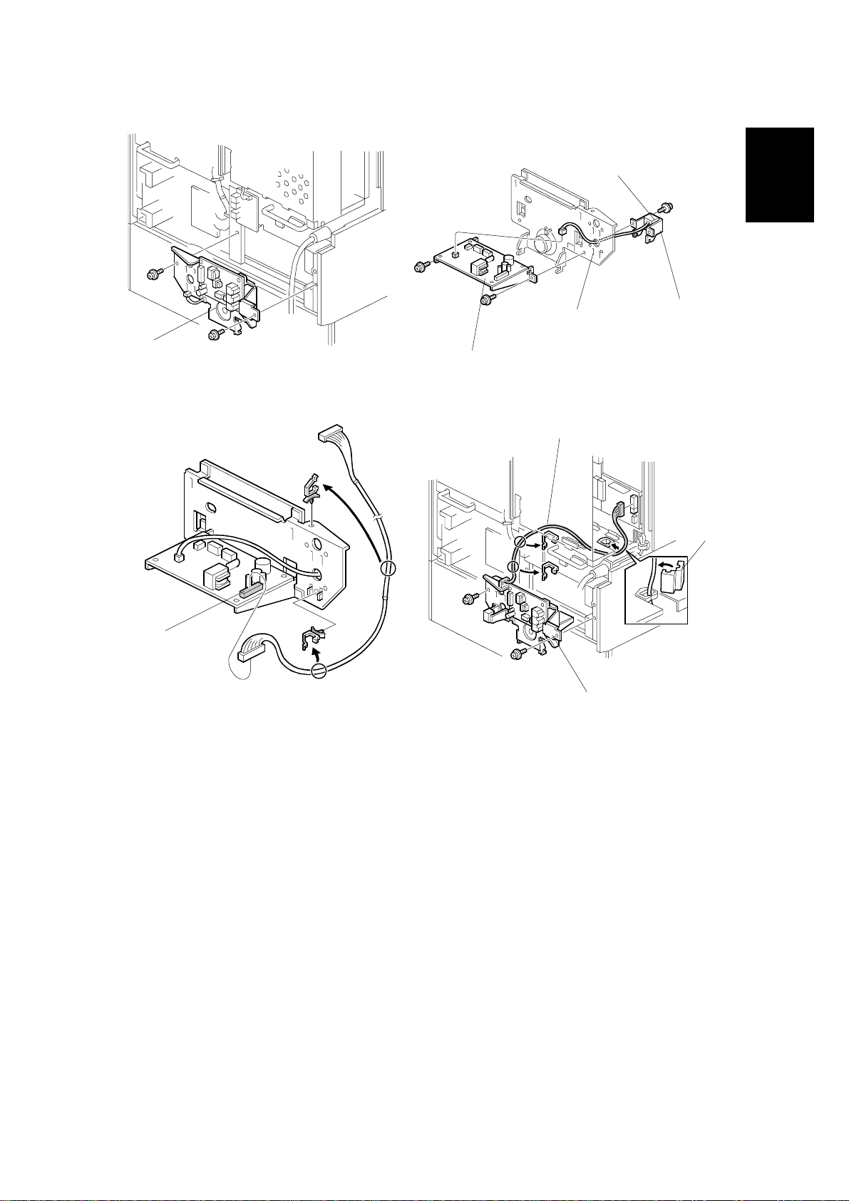
8. Remove the NCU unit [A] (2 screws).
9. Attach the option NCU unit [B] to the lower portion of the reverse side of the
NCU unit (2 screws) as shown. Attach the telephone jack [C] to the bracket [D],
run through the harness through the lower hole [E] in the NCU bracket, then
secure the telephone jack bracket to the NCU unit (1 screw).
10. Connect harness [F] to the option NCU board, then clamp the harness as
shown.
11. Attach the NCU unit [G] to the machine (2 screws), and slide the FCU board
into the machine. Then run through the harness [H] as shown.
12. Attach the ferrite core [I] to the harness.
1-9
Page 13
FAX UNIT 19 January, 2001
[B]
[D]
[E]
[C]
[A]
B366I107-1.WMF
[F]
B367I504.WMF
13. Cut away the small cover [A] for the first option G3 unit.
NOTE: If there is another G3 option unit, cut away the upper small cover [B].
14. Attach the label [C] to the rear cover.
15. Reattach the covers.
B366I105.WMF
NOTE: Attach the second option NCU board [D] and the second option G3 board
[E] to the upper side as shown.
16. Attach the ferrite core [F] to the cable and connect the cable to the LINE2 jack,
then plug in the machine and turn the main switch on.
17. Enter service mode. Set bit 1 of communication switch 16 to “1” for the first
option G3 unit. Set bit 3 of communication switch 16 to “1” for the second
option G3 unit. After that turn the main switch off and on.
18. Print the system parameter list and ensure that “SG3-V34” is listed as an
option.
19. Set up and program the items required for PSTN-2 communications.
1-10
Page 14
19 January, 2001 FAX UNIT
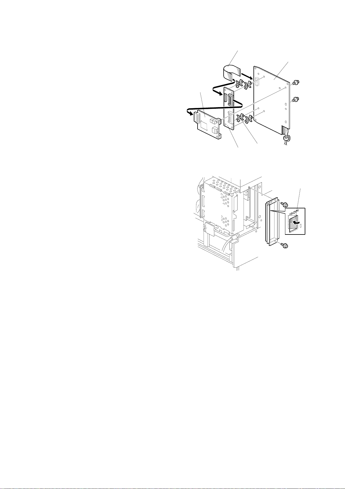
1.1.5 ISDN OPTION TYPE 1045 INSTALLATION
[B]
[A]
Installation
B360I102.WMF
B366I108.WMF
[D]
[C]
B366I101.WMF
!
CAUTION
Before installing this option, do the following:
1. If there is a printer option in the machine, print out all data in the printer
buffer.
2. Turn off the main switch and disconnect the power cord and the STP
cable.
1. Remove the rear cover [A] (2 screws).
2. Remove the FCU cover [B] (2 screws) and controller unit (2 screws).
3. Remove the FCU harness [C] and slide out the FCU board [D] from the
machine.
1-11
Page 15
FAX UNIT 19 January, 2001
[D]
4. Attach the four locking supports [A] to
the CCUIF board [B]. Then attach the
CCUIF board to the FCU board [C] as
shown.
5. Attach the flat cable [D] to the FCU
board and the CCUIF board.
6. Attach the option ISDN board [E] to the
upper connector of the CCUIF board (2
screws).
7. Slide the FCU board into the machine,
and connect the FCU harness.
8. Remove the small plate [F] from the FCU
cover, then reattach the FCU cover (2
screws) and controller unit.
9. Reattach the covers.
10. Connect the cable to the LINE2 jack,
then plug in the machine and turn the
main switch on.
[E]
[B]
[C]
[A]
B367I101.WMF
[F]
11. Enter service mode and set bit 2 of
communication switch 16 to “1”. After
that turn the main switch off and on.
12. Print the system parameter list and
ensure that “SIG4” is listed as an option.
13. Set up and program the items required
for ISDN communications.
14. Affix the FCC/IC approval label on the machine around the ISDN jack (This
step is only for US/Canada.)
B367I102.WMF
1-12
Page 16

19 January, 2001 ERROR CODES
2. TROUBLESHOOTING
2.1 ERROR CODES
If an error code occurs, retry the communication. If the same problem occurs, try to
fix the problem as suggested below. Note that some error codes appear only in the
error code display and on the service report.
Code Meaning Suggested Cause/Action
0-00 DIS/NSF not detecte d within
40 s of Start being pressed
0-01 DCN received unexpectedly
0-03 Incompatible modem at the
other end
0-04 CFR or FTT not received
after modem training
0-05 Unsuccessful after modem
training at 2400 bps
• Check the line connection.
• Check the NCU - FCU connectors.
• The machine at the other end may be
incompatible.
• Replace the NCU or FCU.
• Check for DIS/NSF wit h an oscilloscope.
• If the rx signal is weak, there may be a bad line.
• The other party is out of paper or has a jammed
printer.
• The other party pressed Stop during
communication.
• The other terminal is incompatible.
• Check the line connection.
• Check the NCU - FCU connectors.
• Try changing the tx level and/or cable equalizer
settings.
• Replace the FCU or NCU.
• The other terminal may be faulty; try sending to
another machine.
• If the rx signal is weak or defectiv e, there may be
a bad line.
Cross reference
• Tx level - NCU Pa r ameter 01 (PSTN)
• Cable equalizer - G3 Switch 07 (PSTN)
• Dedicated Tx parameters - Section 4
• Check the line connection.
• Check the NCU - FCU connectors.
• Try adjusting the tx level and/ or cable equalizer.
• Replace the FCU or NCU.
• Check for line problems.
Cross reference
• See error code 0-04.
Trouble-
shooting
2-1
Page 17

ERROR CODES 19 January, 2001
Code Meaning Suggested Cause/Action
0-06 The other terminal did not
reply to DCS
0-07 No post-message response
from the other end after a
page was sent
0-08 The other end sent RTN or
PIN after receiving a page,
because there were too
many errors
0-14
Non-standard post messag e
response code received
• Check the line connection.
• Check the FCU - NCU connectors.
• Try adjusting the tx level and/ or cable equalizer
settings.
• Replace the NCU or FCU.
• The other end may be defective or incompatible;
try sending to another machine.
• Check for line problems.
Cross reference
• See error code 0-04.
• Check the line connection.
• Check the FCU - NCU connectors.
• Replace the NCU or FCU.
• The other end may have jammed or run out o f
paper.
• The other end user may have disconne ct ed t he
call.
• Check for a bad line.
• The other end may be defectiv e; t ry sending to
another machine.
• Check the line connection.
• Check the FCU - NCU connectors.
• Replace the NCU or FCU.
• The other end may have jammed, or run out of
paper or memory space.
• Try adjusting the tx level and/ or cable equalizer
settings.
• The other end may have a defectiv e
modem/NCU/FC U; try sending to another
machine.
• Check for line problems and noise.
Cross reference
• Tx level - NCU Pa r ameter 01 (PSTN)
• Cable equalizer - G3 Switch 07 (PSTN)
• Dedicated Tx parameters - Section 4
• Check the FCU - NCU connectors.
• Incompatible or defective remote terminal; try
sending to another machin e.
• Noisy line: resend.
• Try adjusting the tx level and/ or cable equalizer
settings.
• Replace the NCU or FCU.
Cross reference
• See error code 0-08.
2-2
Page 18

19 January, 2001 ERROR CODES
Code Meaning Suggested Cause/Action
0-15 The other terminal is not
capable of specific
functions.
The other terminal is not capa bl e of a ccepting the
following functions, or the other terminal’s memory
is full.
• Confidential rx
• Transfer function
• SEP/SUB/PWD/SID
0-16 CFR or FTT not detected
after modem training in
confidential or transfer mod e
• Check the line connection.
• Check the FCU - NCU connectors.
• Replace the NCU or FCU.
• Try adjusting the tx level and/ or cable equalizer
settings.
• The other end may have discon nect ed, or it may
be defective; try calli ng another machine.
• If the rx signal level is too low , there may be a
line problem.
Cross reference
• See error code 0-08.
0-17 Communication was
interrupted by pressing the
If the Stop key was not pressed and this error keeps
occurring, replace the operation p anel.
Stop key.
0-20 Facsimile data not received
within 6 s of retraining
• Check the line connection.
• Check the FCU - NCU connectors.
• Replace the NCU or FCU.
• Check for line problems.
• Try calling another fax machine.
• Try adjusting the reconstruction ti me for the first
line and/or rx cable equaliz er setting.
Cross reference
• Reconstruction time - G3 Switch 0A, bit 6
• Rx cable equalizer - G3 Swit ch 07 (PSTN)
0-21 EOL signal (end-of-line)
from the other end not
received within 5 s of the
previous EOL signal
• Check the connection s bet ween the FCU, NCU,
& line.
• Check for line noise or other line problems.
• Replace the NCU or FCU.
• The remote machine may be defective or may
have disconnected.
Cross reference
• Maximum interval between EOLs and between
ECM frames - G3 Bit Switch 0A, bit 4
0-22 The signal from the other
end was interrupted for
more than the acceptable
modem carrier drop time
(default: 200 ms)
• Check the line connection.
• Check the FCU - NCU connectors.
• Replace the NCU or FCU.
• Defective remote terminal.
• Check for line noise or other line problems.
• Try adjusting the acceptable mode m c arrier drop
time.
Cross reference
• Acceptable modem carrier drop time - G3 Sw itch
0A, bits 0 and 1
Trouble-
shooting
2-3
Page 19

ERROR CODES 19 January, 2001
Code Meaning Suggested Cause/Action
0-23 Too many errors during
reception
0-30 The other terminal did not
reply to NSS(A) in AI shor t
protocol mode
0-32 The other terminal sent a
DCS, which contained
functions that the receiv ing
machine cannot handle.
0-52 Polarity changed during
communication
0-70 The communication mode
specified in CM/J M was not
available
(V.8 calling and called
terminal)
• Check the line connection.
• Check the FCU - NCU connectors.
• Replace the NCU or FCU.
• Defective remote terminal.
• Check for line noise or other line problems.
• Try asking the other end to adjust t heir tx level.
• Try adjusting the rx cable equaliz er set t ing an d/ or
rx error criteria.
Cross reference
• Rx cable equalizer - G3 Swit ch 07 (PSTN)
• Rx error criteria - Communication Switch 02, bits
0 and 1
• Check the line connection.
• Check the FCU - NCU connectors.
• Try adjusting the tx level and/ or cable equalizer
settings.
• The other terminal may not be co mp at ible.
Cross reference
• Dedicated tx parameters - Section 4
• Check the protocol dump list .
• Ask the other party to contact the manufacturer.
• Check the line connection.
Retry communication.
• The other terminal did not have a co mpatible
communication mode (e.g., t he ot her t erminal
was a V.34 data modem and not a fax modem.)
• A polling tx file was not ready at t he ot her
terminal when polling rx was initiated from the
calling terminal.
0-74
0-75
0-76 The calling terminal fell back
The calling term inal fell back
to T.30 mode, because it
could not detect ANSam
after sending CI.
The called terminal fell bac k
to T.30 mode, because it
could not detect a CM in
response to ANSam
(ANSam timeout).
to T.30 mode, because it
could not detect a JM in
response to a CM
(CM timeout).
• The calling terminal coul d not detect ANSam due
to noise, etc.
• ANSam was too short to detect.
• Check the line connection an d condition.
• Try making a call to another V.8/ V. 34 fax.
• The terminal could not detect ANSam.
• Check the line connection an d condition.
• Try receiving a call from another V.8/V.34 fax.
• The called terminal could not det ect a CM due to
noise, etc.
• Check the line connection an d condition.
• Try making a call to another V.8/ V. 34 fax.
2-4
Page 20

19 January, 2001 ERROR CODES
Code Meaning Suggested Cause/Action
0-77 The called terminal fell back
to T.30 mode, because it
could not detect a CJ in
response to JM
(JM timeout).
• The calling terminal coul d not det ect a JM due to
noise, etc.
• A network that has narrow bandwidt h cannot
pass JM to the other end.
• Check the line connection an d condition.
• Try receiving a call from another V.8/V.34 fax.
0-79 The called terminal detected
CI while waiting for a V. 21
signal.
0-80
The line was disconnected
due to a timeout in V.34
phase 2 – line probing.
0-81 The line was disconnected
due to a timeout in V.34
phase 3 – equalizer trainin g .
0-82 The line was disconnected
due to a timeout in the V.34
phase 4 – control channel
start-up.
0-83 The line was disconnected
due to a timeout in the V.34
control channel restart
sequence.
Check for line noise or other line problems.
If this error occurs, the called terminal falls back to
T.30 mode.
• The guard timer expired while starting t hese
phases. Serious noise, narrow bandwidth, or low
signal level can cause t hese errors.
If these errors happen at the transmitti ng t erminal:
• Try making a call at a later time.
• Try using V.17 or a slower modem using
dedicated tx parameters.
• Try increasing the tx level.
• Try adjusting the tx cable equa lizer setting.
If these errors happen at the receiving t erminal:
• Try adjusting the rx cable equaliz er set t ing.
• Try increasing the tx level.
• Try using V.17 or a slower modem if the s ame
error is frequent when receiving from multiple
senders.
0-84
0-85
0-86 The line was disconnected
The line was disconnected
due to abnormal signaling in
V.34 phase 4 – control
channel start-up.
The line was disconnected
due to abnormal signaling in
V.34 control channel restart.
because the other terminal
• The signal did not stop within 10 s.
• Turn off the machine, then turn it back on.
• If the same error is frequent, replace the FCU.
• The signal did not stop within 10 s.
• Turn off the machine, then turn it back on.
• If the same error is frequent, replace the FCU.
• The other terminal was incompatible.
• Ask the other party to contact the manufacturer.
requested a data rate using
MPh that was not available
in the currently selected
symbol rate.
0-87
The control channel started
after an unsuccessful
primary channel.
• The receiving terminal restarted the control
channel because data recept ion in the primary
channel was not successfu l.
• This does not result in an error communicat ion.
0-88
The line was disconnected
because PPR was
• Try using a lower data rate at the start.
• Try adjusting the cable equalizer setting.
transmitted/received 9
(default) times within the
same ECM frame.
2-10 The modem cannot enter tx
• Replace the FCU.
mode
2-11 Only one V.21 connection
• Replace the FCU.
flag was received
Trouble-
shooting
2-5
Page 21

ERROR CODES 19 January, 2001
Code Meaning Suggested Cause/Action
2-12 Modem clock irregularity
2-13 Modem initialization error
2-20 Abnormal coding/decoding
(cpu not ready)
2-23
2-24 JBIG ASIC error
2-25 JBIG data reconstruction
2-26
2-27
2-28 JBIG data reconstruction
2-50 The machine resets itself for
2-51 The machine resets itself
3-00 G4 interface board reset
3-10 Disconnection during I S DN
3-11 Disconnection during I S DN
3-20
3-21 A CSA signal was sent
3-30 Mismatched specifications
4-01 Line current was cut
4-10
JBIG compression or
reconstruction error
error (BIH error)
JBIG data reconstruction
error (Float marker error)
JBIG data reconstruction
error (End marker error)
error (Timeout)
a fatal FCU syst em error
because of a fatal
communication error
G3 communication
G4 communication
A CSA signal was received
during ISDN G4
communication
during ISDN G4
communication, becau se t he
Stop key was pressed
(rx capability)
Communication failed
because of an ID Code
mismatch (Closed Network)
or Tel. No./CSI mismatch
(Protection against Wrong
Connections)
• Replace the FCU.
• Turn off the machine, then turn it back on.
• Update the modem ROM.
• Replace the FCU.
• Replace the FCU.
• Turn off the machine, then turn it back on.
• Replace the EXFUNC board i f the error is
frequent.
• Turn off the machine, then turn it back on.
• Replace the EXFUNC board i f the error is
frequent.
• JBIG data error
• Check the sender’s JBIG function.
• Update the FCU ROM .
• If this is frequent, update the ROM, or replace the
FCU.
• If this is frequent, update the ROM, or replace the
FCU.
• Replace the G4 interface board or FCU.
• Check the other terminal and the IS DN line.
• The other terminal may have dialed a wrong
number.
• Check the other terminal and the IS DN line.
• The operator at the other terminal may have
interrupted the communication.
• The local operator has interrupte d t he
communication.
• Check the receive capabilities requested from the
other terminal.
• Check the line connector.
• Check the connection bet w een FCU and NCU.
• Check for line problems.
• Replace the FCU or the NCU .
• Get the ID Codes the same and/or the CSI s
programmed correctly, then resend.
• The machine at the other end may be defective.
2-6
Page 22

19 January, 2001 ERROR CODES
Code Meaning Suggested Cause/Action
5-00 Data construction not
• Replace the FCU.
possible
5-01 Data reconstruction not
possible
5-10 DCR timer expired
5-20 Storage impossible because
of a lack of memory
• Temporary memory shortage.
• Test the SAF memory.
• Replace the FCU or optiona l EXMEM board
5-21 Memory overflow
5-22 Mode table overflow after
the second page of a
scanned document
5-23 Print data error when
printing a substitute rx or
confidential rx message
5-24 Memory overflow after the
second page of a scanned
document
• Wait for the messages which are currently in the
memory to be sent or delete some files from
memory.
• Test the SAF memory.
• Ask the other end to resend the messag e.
• Replace the FCU or optiona l EXMEM board.
• Try using a lower resolution setting.
• Wait for the messages which are currently in the
memory to be sent or delete some files from
memory.
5-25 SAF file access error
6-00 G3 ECM - T1 time out
during reception of facsi m ile
• Replace the FCU or EXMEM board.
• Try adjusting the rx cable equaliz er.
• Replace the FCU or NCU.
data
6-01
G3 ECM - no V.21 signal
was received
6-02
G3 ECM - EOR was
received
6-04 G3 ECM - RTC not detected
• Check the line connection.
• Check connections from t he NCU to the FCU.
• Check for a bad line or defective remote ter minal.
• Replace the FCU or NCU.
6-05 G3 ECM - facsimile data
frame not received within 18
s of CFR, but there was no
line fail
• Check the line connection.
• Check connections from t he NCU to the FCU.
• Check for a bad line or defective remote ter minal.
• Replace the FCU or NCU.
• Try adjusting the rx cable equaliz er
Cross reference
• Rx cable equalizer - G3 Swit ch 07 (PSTN)
6-06 G3 ECM - coding/decoding
error
6-08 G3 ECM - PIP/PIN received
in reply to PPS.NULL
• Defective FCU.
• The other terminal may be defective.
• The other end pressed Stop during
communication.
• The other terminal may be defective.
6-09 G3 ECM - ERR received
• Check for a noisy line.
• Adjust the tx levels of the communicating
machines.
• See code 6-05.
Trouble-
shooting
2-7
Page 23

ERROR CODES 19 January, 2001
Code Meaning Suggested Cause/Action
6-10 G3 ECM - error frames still
received at the other end
after all communication
attempts at 2400 bps
6-21 V.21 flag detected during
high speed modem
communication
6-22
6-99 V.21 signal not stopped
The machine resets the
sequence because of an
abnormal handshake in the
V.34 control channel
within 6 s
• Check for line noise.
• Adjust the tx level (use NCU parameter 01 or the
dedicated tx parameter for that address).
• Check the line connection.
• Defective remote terminal.
• The other terminal may be defective or
incompatible.
• Check for line noise.
• If the same error occurs frequently, replac e t he
FCU.
• Defective remote terminal.
• Replace the FCU.
22-00
22-01 Memory overflow while
22-02 Tx or rx job stalled due to
22-04 The machine cannot store
23-00 Data read timeout during
25-00 The machine software
F0-xx V.34 modem error
F6-8x SG3-V34 modem error
Original length exc eeded the
maximum scan length
receiving
line disconnection at the
other end
received data in the SAF
construction
resets itself after a fatal
transmission error occurred
• Divide the original into more than one page.
• Check the resolution used for sca nning. Lower
the scan resolution if possible.
• Add optional page memory.
• Wait for the files in the queue t o be sent .
• Delete unnecessary files from memory.
• Transfer the substitute reception files t o an
another fax machine, if the machine’s printer is
busy or out of order.
• Add an optional SAF memory card or hard di sk.
• The job started normally but did not finish
normally; data may or may not have been
received fully .
• Restart the machine.
• Update the ROM
• Replace the FCU.
• Restart the machine.
• Replace the FCU
• Update the ROM
• Replace the FCU.
• Replace the FCU.
• Update the SG3-V34 mode m RO M.
• Replace the SG3-V34 boar d.
• Check for line noise or other line problems.
• Try communicating another V.8/V.34 fax.
2-8
Page 24

19 January, 2001 ERROR CODES FOR THE ISDN OPTION
2.2 ERROR CODES FOR THE ISDN OPTION
The tables on the following pages show the error codes for the ISDN option.
The meaning of the numbers in the Action column is as follows.
1. Check Layer 1 signaling with a protocol analyzer to determine the cause of the
problem. This may require assistance from a G4 specialist.
2. Repeat the communication. If the problem does not repeat itself, the problem
was a temporary one caused by the user connecting the machine to another
interface. However, if the problem remains, there is a network problem.
3. There is a network problem.
4. There is a network problem. Do the following:
• Check the error bit rate of the network. If it is high, contact the network and
ask them to improve the line.
• Check the network speed (is it 56 or 64 kbps), and make sure that the bit
switch setting is correct. You may also use the dedicated transmission
parameters if this problem only occurs when dialing certain numbers.
• Check that the user dialed the correct number.
Trouble-
shooting
5. There is a network problem, or a problem in the machine at the other end.
6. There is a problem in the machine at the other end; ask a technician to check it.
7. The machine at the other end is not a Group 4 fax terminal.
8. The machine is not compatible with the machine at the other end. A
compatibility test is needed.
Error codes related to the errors detected by the FCU are listed in the service
manual of the main body.
2-9
Page 25

ERROR CODES FOR THE ISDN OPTION 19 January, 2001
2.2.1 D-CHANNEL LAYER MANAGEMENT
Code Probable Cause Action
7-00 Link reset 2
7-01 Link set-up failed because of ti me-out . 2
7-02 Link release failed because of ti me-out . 2
7-03 Link set-up parameter error 2
2.2.2 D-CHANNEL, L AYER 1
Code Probable Cause Action
7-10 T3 timeout (layer 1 activation error) 1
7-11 No connection on the S0 int erface 1
7-12 Deactivated 1
2.2.3 D-CHANNEL LINK L AYER
Code Probable Cause Action
7-20 At the start of link set-up, the ma chine received an unsolicited S (F=1). 2
7-21 At the start of link set-up, the ma chi ne received an unsolicited DM
(F=1).
7-22 At TEI release, the machine received an unsolicited UA (F=1). 2
7-23 At the start of link set-up, the ma chi ne received an unsolicited DM
(F=0).
7-24 At TEI release, the machine received an unsolicited UA (F=0). 2
7-25 SABME received at the st art of network link set-up No error
7-26 N200 retransmission error for SABME 2
7-27 N200 retransmission error for DISC 2
7-28 N200 retransmission error for situat ion enquiry (RR) 2
7-29 N(R) sequence number error 3
7-30 N(S) sequence number error 3
7-31 FRMR received 3
7-32 Non-standard frame received 3
7-33 Abnormal frame length 3
7-34 N201 error; information field N in the I frame exceeded N201 3
7-35 T201 timeout; timeout whi le w aiting for checking 3
7-36 T202 timeout; timeout while waiting for ID assignment 3
2
2
2-10
Page 26

19 January, 2001 ERROR CODES FOR THE ISDN OPTION
2.2.4 D-CHANNEL NETWORK L AYER
Code Probable Cause Action
7-40 Insufficient mandatory information elements 3
7-41 Abnormal LI for a mandatory information element 3
7-42 T301 timeout; time out while waiting for R:CONN 3
7-43 T303 timeout; timeout w h i le w aiting for R: CALL-PROC etc. 3
7-44 T304 timeout; timeout w h i le w aiting for R: CALL-PROC etc. 3
7-45 T305 timeout; timeout while waiting for R:REL 3
7-46 T308 timeout; timeout while waiting for R:REL-COMP 3
7-47 T310 timeout; timeout w h i le w aiting for R: ALERT etc. 3
7-48 T313 timeout; timeout while waiting for R:CONN-ACK 3
7-49 Internal error 3
7-51 Release call reference during communication 3
2.2.5 B-CHANNEL LINK L AYER
Code Probable Cause Action
7-60 T3 timeout; timeout while wa it ing for flag 4
7-61 T3 timeout; timeout while wa it ing for SABM during an incoming call 4
7-62 T1 timeout x N2; timeout w hi le w aiting for UA after sending SABM 5
7-63
7-64 T1 timeout x N2; timeout whi le waiting for SABM or DISC after sending
7-65 T1 timeout x N2; timeout while waiting for a response to DISC 5
7-66 RNR x N2 (other end busy, RCB counter error) 5
7-67 Invalid (Ad) frame received 5
7-68 Invalid short frame receiv ed 5
7-69 Link reset error 5
7-70 FRMR received 5
7-71 Non-standard (Cn) frame received 5
7-72 An S or U frame having an in formation field was received 5
7-73 A frame longer than the maximum N1 length was received 5
7-74 An S or I frame having an N(R) error w as received 5
7-75 CRC error 3
T1 timeout x N2; timeout whi le w aiting for a response to a transmitted
S frame (P=1)
FRMR
5
5
Trouble-
shooting
2-11
Page 27

ERROR CODES FOR THE ISDN OPTION 19 January, 2001
2.2.6 B-CHANNEL NETWORK L AYER
Code Probable Cause Action
7-80 A packet having an abnorma l G FI w as received 6
7-81 A packet was received that had a l ogical channel number different
from the logical channel be ing used for the communication
7-82 A packet containing a format error was received 6
7-83 A packet containing an LI error was received 7
7-84 A CN packet was received t hat had a PID different from 02 7
7-85 Unsupported packet ty pe received 7
7-86 Abnormal or unsupporte d fac ility received 7
7-87 P(s) sequence number error 6
7-88 P(r) sequence number error 6
7-89 A reset using S:RQ or R:RI occurred 6
7-90 A restart using S:RQ or R:SI occurred 6
7-91 Call set-up error; in reply to S:CR, R:CI wa s received to indicate
rejection of the call
7-92 T20 timeout; timeout whil e w ait ing for an SF packet 6
7-93 T21 timeout; timeout whil e w ait ing for a CC packet 6
7-94 T22 timeout; timeout whil e w ait ing for an RF packet 6
7-95 T23 timeout; timeout whil e w ait ing for a CF packet 6
7-96 T10 timeout; timeout whil e w ait ing for the first frame 6
6
7
2.2.7 TRANSPORT LAYER
Code Probable Cause Action
8-00 Invalid block received 8
8-01 TCC block received 8
8-02 TBR block received 8
8-05 TCR block; block format error 8
8-06 TCR block; block size param et er LI error 8
8-07 TCR block; extended addressing LI error 8
8-08 TCR block; block size length error 8
8-10 TCA block; block format error 8
8-11 TCA block; Tx origin reference data in TCR disagreed with the address
reference data in TCA
8-12 TCA block; octet 7 did not eq ual 0 8
8-13 TCA block; extended addressing LI error 8
8-14 TCA block; block size exce eded that set by TCR 8
8-15 TCA block; block size paramet er LI error 8
8-20 TDT block; block format error 8
8-21 TDT block; octet 3 did not equal either 00 or 80(H) 8
8-22 TDT block; the end indicator was “Continue” even though there was no
field data
8-23 TDT block; an end block with no f ie ld dat a w as received after an end
indicator of “End”
8-26 Timeout during state 0.2 8
8-27 Timeout during state 1.1 8
8-28 Timeout during state 0.3 8
8
8
8
2-12
Page 28

19 January, 2001 ERROR CODES FOR THE ISDN OPTION
2.2.8 SESSION LAYER
Code Probable Cause Action
8-30 Invalid frame receiv ed 8
8-31 RSSN received 8
8-32 CSA received 8
8-34 Calling terminal identification error in CSS 8
8-35 Date and time error in CSS 8
8-36 Window size error in CSS 8
8-37 Service identification error in CSS 8
8-38 Session user data error in CSS 8
8-39 CSS rejected (new session reject ed) 8
8-40 Called terminal identification error in RSSP 8
8-41 Date and time error in RSSP 8
8-42 Date and time in RSSP was n ot the same as that in CSS 8
8-43 Window size error in RSSP 8
8-44 Service identificat ion error in RSSP 8
8-45 Session user data error in RSSP 8
8-47 Message synchronization error inside the CCU 8
8-48 Document task busy 8
8-50 Ti timeout; non-communicat ion surveillance timer (T.62) 8
8-51 T2 timeout; timeout while waiting for a response (T.62) 8
8-52 T3 timeout; CSA timer timeout (T.62) 8
8-53 G4 board load timer timeout; call ing side waited too long for a new
session
8-54 G4 board load timer timeout; calling side waited too long for transport
probability
8-55 G4 board load timer timeout; called side waited too long for S:RSSP 8
8-56 G4 board load timer timeout; docume nt t ransmission surveillance t imer
timeout
8-57 G4 board load timer timeout; timeout w hi le waiting for a user abort
request after a provider fail
8
8
8
8
Trouble-
shooting
2-13
Page 29

ERROR CODES FOR THE ISDN OPTION 19 January, 2001
2.2.9 DOCUMENT LAYER
Code Probable Cause Action
8-60 T.62 coding format error (LI error) 8
8-61 A mandatory PI was absent, or the LI for a man dat ory PI was 0 8
8-62
8-63 The LI for session user data exceeded t he maximum value (512) 8
8-64 The LI for CDUI was not 0 8
8-65 Checkpoint and document reference numbers LI error, or they were
8-66 The checkpoint reference nu mb er di ffered from the expected value 8
8-70 RDGR received 8
8-71 A non-standard PDU was received while in calling mode 8
8-72 A non-standard PDU was received while in called mode 8
8-73 Abnormal PDU received while in calling state ds1 8
8-74 15 consecutive CDCL signals received 8
8-75 Session window size cont rol error (size not equal to 0) 8
8-76 Internal error 8
Calling/called t erminal identification LI was different from that specified
by F.184 (LI = 24)
not in T.61 (ASCII) coding
8
8
2.2.10 PRESENTATION LAYER
Code Probable Cause Action
8-80 X.209 coding error in session user data (LI error) 8
8-81 PV error in session user data 8
8-82 PI error in session user data 8
8-83 The capabilities in t he session user data of CDS/CDC were not the
same as those in RDCLP
8-84 X.209 coding error in the DP (LI error) 8
8-85 X.209 coding error in the SLD (docu ment descriptor/page descriptor)
(LI error)
8-86 SLD object type absen t 8
8-87 PI error in the SLD (document descript or/ page descriptor) 8
8-88
8-89 No document descriptor at the st art of the document 8
8-90 No page descriptor at the start of the page 8
8-91 Page descriptor PV error 8
8-92 X.209 coding error in the TU (LI error) 8
8-93 The TU was absent 8
8-94 PV error in the TU 8
8-95 TI error 8
8-96 X.209 coding nest level >> 8, or an LI form error 8
8-97 CDPB/CDE received while T U/TI not yet completed, or an unexpected
The capabilities in the SLD (document descriptor/page descriptor) are
duplicated or are not the same as those in RDCLP
PDU was received wh ile analyzing an SLD
8
8
8
8
2-14
Page 30

19 January, 2001 FAX SC CODES
2.3 FAX SC CODES
2.3.1 OVERVIEW
When the FCU detects a Fax SC Code condition other than SC1201 and SC1207,
it resets itself automatically (default setting). This initializes the FCU without
erasing files in the SA F memory or resetting the switches.
NOTE: For details on Fax SC Codes 1201 and 1207, refer to the following
sections.
If bit 7 of System Switch 1F is changed to “1”, when the FCU detects a Fax SC
Code condition, it displays the code on the display and stops working until the fax
unit is initialized using one of the following me thods:
• Hold down the “#” and “*” keys for more than 10 s.
• Turn off the main power switch and turn it back on.
2.3.2 SC1201
When the FCU detects an unrecoverable error in the SRAM, which requires a
complete SRAM initialization, the fax unit displays this SC Code and stops.
There is no way to recover from this error condition without a complete SRAM
initialization (all the user and service programmed data will be erased).
Trouble-
shooting
The possible causes are:
• SRAM backup battery defect, or SW1 on the FCU is at th e “OFF” position
• SRAM on the FCU has a physical defect
• Flash memory card or data copy tool connection was loose
2.3.3 SC1207
This is the same as SC1201 except the error location is the SRAM on the Fax
Function Upgrade board.
The possible causes are:
• SRAM backup battery defect, or SW1 on the Fax Function Upgrade board is at
the “OFF” position.
• SRAM on the Fax Function Upgrade board has a physical defect.
• The Fax Function Upgrade board connection was loose.
2-15
Page 31

FAX SC CODES 19 January, 2001
2.3.4 FAX SC CODE TABLE
SC Code Description
1102 Handshake error with
controller at start-up
1111 Command TX/RX error
to/from the controller
1112 Base copier’s engine was
reset
1120 Interface module error
1201
1207
1299
1305
1310
1311
1312
1401
1405
1601
Unrecoverable FCU -
SRAM error
Unrecoverable Fax
Function Upgrade -
SRAM error
Software error
Suggested
Action
Initialize the fax
unit.
(See section
2.3.1.for the
initialization
procedure)
Refer to section
2.3.2.
Refer to section
2.3.3.
Initialize the fax
unit.
Sys Switch
1F bit 7 = 0
Automatic
reset
“Service Call”
display
“Service Call”
display
Automatic
reset
Sys Switch
1F bit 7 = 1
SC Code
display
2-16
Page 32

19 January, 2001 ISDN TEST FUNCTION
2.4 ISDN TEST FUNCTION
2.4.1 LEDS
There are four LEDs on the G4 board. These LEDs describe the status of the
machine.
LED 1 LED 2 LED 3 LED 4
Initial Settings O=ON, --=OFF
Initial check (if the flash ROM is updated) O O O O
Handshaking with the FCU ready O O -- --
Standby Mode
Ready to communicate -- -- -- --
Communication
Layer 1 activated -- -- -- O
Trouble-
shooting
Link setup -- -- O O
B channel 1 connected -- O O O
B channel 2 connected O -- O O
2-17
Page 33

ISDN TEST FUNCTION 19 January, 2001
2.4.2 BACK-TO-BACK TEST
To make a back-to-back test, you need:
• Two machines, one with the CiG4 board (G4 board used in the FX4, FR4,
ADAM, NAD, Stinger, and Russian) and the other with the SiG4 board (G4
board used with the Schmidt 3, S4, and Kaiser 1).
• Cross rosette
NOTE: You cannot make a back-to-back test using two SiG4 machines.
The procedure is as follows.
1. Switch off the machines
2. Connect two machines back-to-back using a cross rosette as follows.
1
2
3
4
5
6
7
8
Machine A Machine B
Cross Rosette
1
2
3
4
5
6
7
8
1
2
3
4
5
6
7
8
H535T601.WMF
3. Make the following bit switch adjustments:
• In the machine acting in NT mode (CiG4 board), set bits 0 and 1 of G4
parameter switch 0D to 1.
• In the machine acting in TE mode (SiG4 board) set bit 0 of G4 parameter
switch 0D to 0 and bit 1 to 1.
4. Reset the machines by switching them off, waiting a few seconds, then
switching back on.
5. Place a document in one of the machines, dial a number, then press Start.
6. After you have finished the test, set bits 0 and 1 of G4 parameter switch 0D
back to 0, then reset the machine.
NOTE: The following cannot be tested using this procedure:
• ISDN G3 communication
• Point to Multi (Like a broadcasting test, f rom one point to many places.)
2-18
Page 34

19 January, 2001 SERVICE PROGRAM MODE
3. SERVICE TABLES
!
CAUTION
Never turn off the main power switch when the power LED is lit or flashing.
To avoid damaging the hard disk or memory, press the operation power
switch to switch the power off, wait for the power LED to go off, and then
switch the main power switch off.
NOTE: The main power LED ( ) lights or flashes while the platen cover or
ARDF is open, while the main machine is communicating with a facsimile
or the network server, or while the machine is accessing the hard disk or
memory for reading or writing data.
3.1 SERVICE PROGRAM MODE
3.1.1 SERVICE PROGRAM MODE OPERATION
Tables
Service
The service program (SP) mode is used to check electrical da ta, change modes,
and adjust values.
Entering and Exiting SP mode
1
"
#$%
∀
Fax SP
Exit
Press the Clear Mode key.
.
2.Use the keypad to enter “107”.
3
Hold down Clear/Stop for at least 3 seconds.
.
4.On the touch-panel, press Fax SP.
5
Press Exit twice to return to the co py window.
.
3-1
Page 35

SERVICE PROGRAM MODE 19 January, 2001
SP Mode Button Summary
Here is a short summary of the touch-panel buttons.
B004S500.WMF
Opens all SP groups and su blevels.
!!!!
Closes all open groups and s ublevels and restores the initial SP mode displ ay.
""""
Not used for the Fax SP mode.
####
Enter the SP mode directly w it h t he number keys if you know the SP number and then
$$$$
press &. (SP Mode must be highlighted before you can enter the number. Just press SP
Mode if it is not highlight ed.)
Press twice to leave the SP mode return to the copy window to resume normal operation.
%%%%
Press any Group number to open a list o f S P mode s and t itles for that group. For
&&&&
example, to open the SP mode list for SP1-nnn , press Group1. If an SP has sublevels,
click the appropriate button t o expand the list.
Press to scroll the display t o t he previous or next group.
''''
Press to scroll to the previous or next display in segments the size of the screen display
((((
(page).
Press to scroll the display t o t he previous or next line, line by line.
))))
Press to move to the highlig ht to the previous or next selection in the list on the left.
****
3-2
Page 36

19 January, 2001 SERVICE PROGRAM MODE
Switching Between SP Mode and Copy Mode for Test Printing
1) In the SP mode, select the test print and then press Copy Window.
2) Use the copy window (copier mode), to select the appropriate settings
(paper size, etc.) for the test print.
3) Press Start ' to execute the test print.
4) Press SP Mode (highlighted) to return to the SP mode screen and repeat
from step 1.
Selecting the Program Number
Program numbers have two or three levels.
1. Before you begin, refer to the Service Tables to find the SP that you want to
adjust. (☛ 3.1.2)
2. Click the Group number on the left side SP Mode window that contains the SP
that you want to adjust.
3. Use the scrolling buttons in the center of the SP mode window to display the
SP number that you want to open, and then press that number to expand the
list.
Tables
Service
4. Use the center touch-panel buttons to scroll to the number and title of the item
that you want to set and press. The small entry box on the right is activated and
displays the default or the current setting below.
B004S501.WMF
Refer to the Service Tables for the range of allowed settings. (☛ 3.1.2)
1. To enter a setting”
• Press ! to toggle between plus and minus and then use the keypad to enter
the appropriate number. The number you enter write over the previous
setting.
• Press & to enter the setting. (If you enter a number that is out of range, the
key press is ignored.)
• When you are prompted to complet e the selection, press Yes.
2. When you are finished, press Exit twice to return to the copy window.
3-3
Page 37

SERVICE PROGRAM MODE 19 January, 2001
3.1.2 SERVICE PROGRAM MODE TABLES
SP1-XXX (Bit Switches)
1
System Switch101
001 – 032 00 – 1F Change the bit switches for system settings
Scanner Switch102
001 – 016 00 – 0F Change the bit switches for scanner
Printer Switch103
001 – 016 00 – 0F Change the bit switches for printer settings
Communicati on Switch104
001 – 032 00 – 1F Change the bit switches for c ommunication
G3-1 Switch105
001 – 016 00 – 0F Change the bit switches for the protocol
G3-2 Switch106
001 – 016 00 – 0F Change the bit switches for the protocol
G3-3 Switch107
001 – 016 00 – 0F
G4 Internal Switch108
001 – 032 00 – 1F Change the bit switches for the optional
G4 Parameter Switch109
001 – 016 00 – 0F
Mode No. Function
☛ Section 3.2 Bit Switches
for the fax option
☛ Section 3.2 Bit Sw it ches
settings for the fax option
☛ Section 3.2 Bit Sw it ches
for the fax option
☛ Section 3.2 Bit Sw it ches
settings for the fax option
☛ Section 3.2 Bit Sw it ches
settings of the standard G3 board ☛
Section 3.2 Bit Switches
settings of the optional G3 board
☛ Section 3.2 Bit Sw it ches
Change the bit switches for the protocol
settings of the optional G3 board
☛ Section 3.2 Bit Sw it ches
ISDN settings ☛
Section 3.2 Bit Switches
Change the bit switch es for opt ional ISDN
parameters
☛ Section 3.2 Bit Sw it ches
3-4
Page 38

19 January, 2001 SERVICE PROGRAM MODE
SP2-XXX (RAM Data)
2
102
RAM Read/ Writ e101
001 Change R AM data f or t he fa x board directly.
Memory Dump
001 G3-1 Memory Dump
002 G3-2 Memory Dump Print out RAM data for the SG3-1 board.
003 G3-3 Memory Dump Print out RAM data for the SG3-2 board.
004 G4 Memory Dump Print out RAM data for the SiG4 b oard.
G3-1 NCU Parameters103
001 – 023 CC, 01 – 22 NCU parameter settings for the standard
G3-2 NCU Parameters104
001 – 023 CC, 01 – 22
G3-3 NCU Parameters105
001 – 023 CC, 01 – 22
Mode No. Function
SP3-XXX (Tel Line Settings)
☛ Section 3.5 Service RAM Addresses
Print out RAM data for the fax board. ☛
Section 3.5 Service RAM Addre sses
G3 board. ☛ Section 3.3 NCU Parameters
NCU parameter settings for the optional G3
board. ☛ Section 3.3 NCU Parameters
NCU parameter settings for the optional G3
board. ☛ Section 3.3 NCU Parameters
Tables
Service
3
101
103
104 PSTN-2 Port Settings
Service Station
001 Fax Number Enter the fax number of the service stati on.
002 Select Line Select t he line type.
Serial Number102
000 Enter the fax unit’s serial nu mber.
PSTN-1 Port Settings
001 Select Line Select the line type setting for the G3-1 line.
002 PSTN Access Number Enter the PSTN access number for the
003 Memory Lock
004 Transmission
001 Select Line Select the line setting for the G3-2 line. If
002 PSTN Access Number Enter the PSTN access number for the G 3-
Mode No. Function
Disabled
Disabled
If the machine is installed on a PABX line,
select “PABX”, “ PABX(GND)” or
“PABX(FLASH)”.
G3-1 line.
If the customer does not want to receive
transmissions using Me mory Lock on this
line, turn this SP on.
If you turn this SP on, the machine does not
send any fax messages on the G3-1 lin e.
the machine is installed on a PABX line,
select “PABX”, “ PABX(GND)” or
“PABX(FLASH)”.
2 line.
3-5
Page 39

SERVICE PROGRAM MODE 19 January, 2001
3
003
004 Transmission
105 PSTN-3 Port settings
001 Select Line
002 PSTN Access Number
003
004 Transmission
106 ISDN Port Settings
001 Select Line
002 PSTN Access Number Enter the PSTN access number for IS D N
003
004 Transmission
Mode No. Function
Memory Lock
Disabled
Disabled
Memory Lock
Disabled
Disabled
Memory Lock
Disabled
Disabled
If the customer does not want to receive
transmissions using Me mory Lock on this
line, change this SP to on.
If you turn this SP on, the machine does not
send any fax messages on the G3-2 lin e.
Select the line setting for the G3-3 l ine. I f
the machine is installed on a PABX line,
select “PABX”, “ PABX(GND)” or
“PABX(FLASH)”.
Enter the PSTN access number for the G33 line.
If the customer does not want to receive
transmissions using Me mory Lock on this
line, change this SP to on
If you turn this SP on, the machine does not
send any fax messages on the G3-3 lin e.
Select the line setting for the ISDN line. If
the machine is instal led t o t he PABX line,
select “PABX”.
line.
If the customer does not want to receive
transmissions using Me mory Lock on this
line, change this SP to on
If you turn this SP on, the machine does not
send any fax messages on the IS DN line.
SP4-XXX (ROM Versions)
4
101 001 FCU ROM Version Displays the FCU ROM version.
102 001 Error Codes Displays t he lat est 64 fax error codes.
103 001 G3-1 ROM Version Displays the G3-1 mode m v ersi on.
104 001 G3-2 ROM Version Displays the G3-2 mode m v ersi on.
105 001 G3-3 ROM Version Displays the G3-3 mode m v ersi on.
106 001 G4 ROM Version Displays the G4 (ISDN) ROM version.
107 001 Charge ROM Version Not used.
Mode No. Function
3-6
Page 40

19 January, 2001 SERVICE PROGRAM MODE
SP5-XXX (Initializing)
5
105
Mode No. Function
Initialize S RAM101
000 Initializes the bit switches and u ser
parameters, user data in the SRAM, files in
the SAF memory, and clock.
Erase All Files102
000 Erases all files stored in the SAF memory.
Reset Bit Switches103
000
Factory setting104
000 Resets the bit switches and user
Delete All Speed Dials
001 Speed Dials Enabled 200 speed dials and 1000 quick dials are
002 Speed Dials Disabled 1200 quick dials (but no speed dials) are
Resets the bit switches and user
parameters.
parameters, user data in the SRAM and
files in the SAF memory.
available when the Fax F unct i on Upgrade
Unit is instal led.
available when the Fax F unct i on U pgrade
Unit is instal led.
Tables
Service
SP6-XXX (Reports)
6
System Parameter List101
000
Service Monitor Report102
000
103 G3 Protocol Dump List
001
002 G3-1 (All
003 G3-1 (1
004
005 G3-2 (1
006 G3-3 (All
007 G3-3 (1
Mode No. Function
G3 All
Communications
Communications)
Communication)
G3-2 (All
Communications)
Communication)
Communications)
Communication)
Touch the “ON” button to print t he system
parameter list.
Touch the “ON” button to print t he service
monitor report.
Prints the protocol dump list of all
communicatio ns for all G3 lines.
Prints the protocol dump list of all
communications for the G3-1 li ne.
Prints the protocol dump list of the last
communication for the G3-1 line.
Prints the protocol dump list of all
communications for the G3-2 li ne.
Prints the protocol dump list of the last
communication for the G3-2 line.
Prints the protocol dump list of all
communications for the G3-3 li ne.
Prints the protocol dump list of the last
communication for the G3-3 line.
3-7
Page 41

SERVICE PROGRAM MODE 19 January, 2001
6
104 G4 Protocol Dump List
001 Dch + Bch 1
002 Dch
003 Bch 1 Link Layer
004 Dch Link Layer
005 Dch +Bch 2
006 Bch 2 Link Layer
105 All Files print out
000 Prints out all the user files in the SAF
106 Journal Print out
001 All Journals The machine prints all the communication
002 Specified Date
107 Log List Print out
001 All log files
002 APIP
003 Mail Box
004 Operation
005 Printer APIP
006 SC/TRAP Stored
007 Scanner
008 JOB/SAF
009 Decompression
010 Reconstruction
011 JBIG
012 Fax Driver
013 G3CCU
014 Fax Job
Mode No. Function
Prints the protocol dump lists for the G4
line.
memory, including confidential messages.
NOTE: Do not use this function, unless
the customer is having trouble
printing confidential messages or
recovering files stored using the
memory lock feature.
records on the report.
The machine prints all commu nication
records after the specified date.
These log print out function s are f or
designer use only.
3-8
Page 42

19 January, 2001 SERVICE PROGRAM MODE
SP7-XXX (Test Modes)
These are the test modes for PTT approval.
Function
7
101 G3-1 Modem Tests
102 G3-1 DTMF Tests
103 Ringer Test
104 G3-1 V34 (S2400baud)
105 G3-1 V34 (S2800baud)
106 G3-1 V34 (S3000baud)
107 G3-1 V34 (S3200baud)
108 G3-1 V34 (S3429baud)
109 Recorded Message Test
110 G3-2 Modem Tests
111 G3-2 DTMF Tests
112 G3-2 V34 (S2400baud)
113 G3-2 V34 (S2800baud)
114 G3-2 V34 (S3000baud)
115 G3-2 V34 (S3200baud)
116 G3-2 V34 (S3429baud)
117 G3-3 Modem Tests
118 G3-3 DTMF Tests
119 G3-3 V34 (S2400baud)
120 G3-3 V34 (S2800baud)
121 G3-3 V34 (S3000baud)
122 G3-3 V34 (S3200baud)
123 G3-3 V34 (S3429baud)
124 IG3-1 Modem Tests
125 IG3-1 DTMF Tests
126 IG3-1 V34 (S2400baud)
127 IG3-1 V34 (S2800baud)
128 IG3-1 V34 (S3000baud)
129 IG3-1 V34 (S3200baud)
130 IG3-1 V34 (S3429baud)
131 IG3-2 Modem Tests
132 IG3-2 DTMF Tests
133 IG3-2 V34 (S2400baud)
134 IG3-2 V34 (S2800baud)
135 IG3-2 V34 (S3000baud)
136 IG3-2 V34 (S3200baud)
137 IG3-2 V34 (S3429baud)
Tables
Service
3-9
Page 43

BIT SWITCHES 19 January, 2001
3.2 BIT SWITCHES
!
WARNING
Do not adjust a bit switch or use a setting that is described as “Not used”,
as this may cause the machine to malfunction or to operate in a manner
that is not accepted by local regulations. Such bits are for use only in other
areas, such as Japan.
NOTE: Default settings for bit switches are not listed in this manual. Refer to the
System Parameter List printed by the machine.
3.2.1 SYSTEM SWITCHES
System Switch 00 SP No. 1-101-001
No FUNCTION COMMENTS
Dedicated transmiss ion
0
parameter programming
0: Disabled 1: Enabled
1 Confidential RX message print
out without the password.
0: Disabled 1: Enabled
Technical data printout on the
2
Journal
0: Disabled
1: Enabled
Set this bit to 1 before changing any dedicated
transmission parameters.
Reset this bit to 0 after programming dedicated
transmission parameters.
1: Confidential RX messages can be printed out
without the password. Use th is bit if the customer
forgot the password for the confid ent ial messages.
Reset this bit to 0 after printing confidential RX
messages.
1: Instead of the personal name, t he f ol low i ng data
are listed on the Journal for each G 3
communication.
e.g. 0000 32V34 288/264 L0100 03 04
(1) (2)(3) (4) (5) (6) (7) (8)
(1): EQM value (Line quality data). A larger number means more errors.
(2): Symbol rate (V.34 only)
(3): Final modem type used
(4): Starting data rate (for example, 288 means 28.8 kbps)
(5): Final data rate
(6): Rx revel (refer to the note after this table for how to read the rx level)
(7): Total number of error lines that occurred during non-ECM reception.
(8): Total number of burst error lines that occurred during non-ECM reception.
Note:
EQM and rx level are fixed at “FFFF” in tx mode.
The seventh and eighth numbers are fixed at “00” for transmission r ecor ds and
ECM reception records.
3-10
Page 44

19 January, 2001 BIT SWITCHES
System Switch 00 SP No. 1-101-001
No FUNCTION COMMENTS
2 Rx level calculation
Example: 0000 32 V34 288/264 L 01 00
03 04
The four-digit hexadeci mal value (N) after “L” indicates the rx level.
The high byte is given first, follow ed by the low
byte. Divide the decimal value of N by -
16 to get the rx level.
In the above example, the decimal value of N (= 0100 [H]) is 256.
So, the actual rx level is 256/ -16 = -16 dB
3-4 Not used Do not change the settings.
5 G3/G4 communication
parameter display
0: Disabled
1: Enabled
6 Protocol dump list output after
each communication
0: Off
1: On
This is a fault-finding aid. The LCD shows the key
parameters (see below). Th is is normally disabled
because it cancels the CSI display for the user.
Be sure to reset this bit to 0 after testing.
This is only used for communication
troubleshooting. I t shows the content of the
transmitted facsimile protocol signals. Always reset
this bit to 0 after finishing testing.
If system switch 09 bit 6 is at “1”, t he list is only
printed if there was an error during the
communication.
7 Not used Do not change the setting.
G3 Communication Parameters
Tables
Service
Modem rate 336: 33600 bps 168: 16800 bps
312: 31200 bps 144: 14400 bps
288: 28800 bps 120: 12000 bps
264: 26400 bps 96: 9600 bps
240: 24000 bps 72: 7200 bps
216: 21600 bps 48: 4800 bps
192: 19200 bps 24: 2400 bps
Resolution S: Standard (8 x 3.85 dots/mm)
D: Detail (8 x 7.7 d ots/mm)
F: Fine (8 x 15.4 dots/mm)
SF: Superfine (16 x 15.4 dots/mm)
21: Standard (200 x 100 dpi)
22: Detail (200 x 200 dpi)
44: Superfine (400 x 400 dpi)
Compression mode MMR: MMR compression
MR: MR compression
MH: MH compression
JBO: JBIG compression (Opti onal mode)
JBB: JBIG compression (Basic mode)
Communication
mode
Width and
reduction
ECM: With ECM
NML: With no ECM
A4: A4 (8.3"), no reduction
B4: B4 (10.1"), no reduction
A3: A3 (11.7"), no reduction
3-11
Page 45

BIT SWITCHES 19 January, 2001
I/O rate 0: 0 ms/line 10: 10 ms/line
25: 2.5 ms/line 20: 20 ms/line
5: 5 ms/line 40: 40 ms/line
Note:
“40” is displayed while receiv ing a fax message using AI short
protocol.
G4 Communication Parameters
Compression mode MMR: MMR compression
MR: MR compression
MH: MH compression
Resolution
Width and
reduction
Transfer
Confidential C: Confidential
Other parameters
21: Standard (200 x 100 dpi)
22: Detail (200 x 200 dpi)
44: Superfine (400 x 400 dpi)
A4: A4 (8.3"), no reduction
B4: B4 (10.1"), no reduction
A3: A3 (11.7"), no reduction
T: Transfer
- : Other
- : Other
The following information is shown in 6-bit format. Bit 1 is the first
bit from the left, and bit 6 is at the right end.
Bit 1 - Smoothing 0: Off, 1: On
(Smoothing is disabled in halftone mode.)
Bit 2 - CIL printing 0: On, 1: Off
Bit 3 - Not used
Bit 4 - mm/inch conversion 0: Off, 1: On
Bit 5 - Engine type 0: mm, 1: inches
Bit 6 - Document resolution unit 0: mm, 1: inches
System Switch 01 - Not used (Do n ot change the factory settings.)
System Switch 02 SP No. 1-101-003
No FUNCTION COMMENTS
0-3 Not used Do not change the settings.
File retention time
4
0: Depends on User Parameter
24 [18(H)]
1: No limit
5 Not used Do not change the settings.
1: A file that had a communication error w i ll not be
erased unless the communication is successful.
3-12
Page 46

19 January, 2001 BIT SWITCHES
System Switch 02 SP No. 1-101-003
No FUNCTION COMMENTS
6
Memory read/write by RDS
7
Bit 7 6 Setting
0 0 Always disabled
0 1 User selectable
1 0 User selectable
1 1 Always enabled
(0,0): All RDS systems are alway s locked out.
(0,1), (1,0): Normally, RDS syst ems are locked out,
but the user can temporarily sw it ch RDS on to allow
RDS operations to take place. RDS will
automatically be locked out again after a certain
time, which is stored in System Switch 03. Note that
if an RDS operation takes place, RDS will not switch
off until this time limit has expired.
(1,1): At any time, an RDS system can ac cess t he
machine.
System Switch 03 SP No. 1-101-004
No FUNCTION COMMENTS
0
Length of time that RDS i s
to
temporarily switched on when
7
bits 6 and 7 of System Swit ch
02 are set to “User selectable”
00 - 99 hours (BCD).
This setting is only valid if bits 6 and 7 of System
Switch 02 are set to “User selectable”.
The default setting is 24 hours.
Tables
Service
System Switch 04 SP No. 1-101-005
No FUNCTION COMMENTS
0-2 Not used Do not change the settings.
3 Printing dedicated tx
parameters on Quick/Speed
Dial Lists
0: Disabled
1: Enabled
1: Each Quick/Speed d ial number on the list is
printed with the dedicated tx parameters (10 bytes
each).
The first 10 bytes of data are the programmed
dedicated tx parameters; 34 by t es of data are
printed (the other 24 bytes have no use for serv ice
technicians).
4-7 Not used Do not change the settings.
System Switch 05 - Not used (Do n ot change the factory settings.)
System Switch 06 SP No. 1-101-007
No FUNCTION COMMENTS
0
Margin setting for Create
to
Margin Transmission
7
71 to 99 (BCD) %. This setting determines the
reduction ratio when the user uses the Creat e
Margin Transmission feature.
Default setting:1001 001 1 (93%)
System Switch 07 - Not used (Do not change the factory settings.)
System Switch 08 - Not used (Do n ot change the factory settings.)
3-13
Page 47

BIT SWITCHES 19 January, 2001
System Switch 09 SP No. 1-101-010
No FUNCTION COMMENTS
0 Addition of image data from
confidential trans missions on
the transmission result report
0: Disabled 1: Enabled
1 Inclusion of communications on
the Journal when no image
data was exchanged.
0: Disabled 1: Enabled
2 Automatic error report printout
0: Disabled 1: Enabled
3 Printing of the error code on the
error report
0: No 1: Yes
4 Not used Do not change the settings.
5 Power failure report
0: Disabled 1: Enabled
6 Conditions for printing the
protocol dump list
0: Print for all communications
1: Print only when there is a
communication error
Priority given to various types
7
of remote terminal ID when
printing reports
0: RTI > CSI > Dia l label > Tel.
number
1: Dial label > Tel. number >
RTI > CSI
If this feature is enabled, the top half of the first
page of confidential messages will be printed on
transmission result reports.
0: Communications that reached phase C (message
tx/rx) of the T.30 protocol are li st ed on t he Journal.
1: Communications that reached phase A (call
setup) of T.30 protocol are listed on t he Journal.
This will include telep hone calls.
0: Error reports will not be printed.
1: Error reports will be printed auto matically after
failed communications.
1: Error codes are printed on the error reports.
1: A power failure repor t will be automatically printed
after the power is switched on if a fax me ssage
disappeared from the memory when the power was
turned off last.
This switch becomes effect ive only when system
switch 00 bit 6 is set to 1.
1: Set this bit to 1 when you wish to print a prot ocol
dump list only for communications w ith errors.
This bit determines which set of priorities the
machine uses when listing remote terminal names
on reports.
In G4 communication, G4_TID (Terminal ID) is used
instead of RTI or CSI.
Dial Label: The na me store d, by the user, for the
Quick/Speed Dial number.
3-14
Page 48

19 January, 2001 BIT SWITCHES
System Switch 0A SP No. 1-101-011
No FUNCTION COMMENTS
0-2 Not used Do not change the settings.
3 Continuous polling reception
0: Disabled 1: Enabled
This feature allows a series of stations to be polled
in a continuous cycle. This will continue until the
polling reception file is eras ed.
The dialing interval is the same as memory
transmission.
4 Dialing on the ten-key pad
when the external telephone is
off-hook
0: Disabled 1: Enabled
0: Prevents dialing fro m the t en-key pad while the
external telephone is off-hook. Use this setting when
the external telephone is n ot by the machine, or if a
wireless telephone is connected as an external
telephone.
1: The user can dial on the machine’s t en-key pad
when the handset is off-hoo k.
5 On hook dial
0: On hook dial is disabled.
0: Disabled 1: Enabled
6 Line used for G3 transmission
0: PSTN 1: ISDN
If an ISDN unit has bee n inst alled, this bit
determines whether G3 trans missions go out over
the PSTN or the ISDN.
7 Line used when the machine
falls back to G3 from G4 if the
This bit switch has no ef fect if Communication
Switch 07 bit 0 is set to 0.
other end is not a G4 machine
0: PSTN 1: ISDN
Tables
Service
System Switch 0B - Not used (Do not change the factory settings.)
System Switch 0C - Not used (Do not change the factory settings.)
System Switch 0D - Not used (Do not change the factory settings.)
System Switch 0E SP No. 1-101-015
No FUNCTION COMMENTS
0-2 Not used Do not change the settings.
3 Action when the external
handset goes off-hook
0: Manual tx and rx operation
1: Memory tx and rx operation
(the display remains the same)
0: Manual tx and rx are possible whi le the ext ernal
handset is off-hook. Howev er, me mory tx is not
possible.
1: The display stays in standby mode even when
the external handset is used, so that ot her people
can use the machine for memory tx operation.
Note that manual tx and rx are not po ssi ble with this
setting.
4-7 Not used Do not change the settings.
3-15
Page 49

BIT SWITCHES 19 January, 2001
System Switch 0F SP No. 1-101-016
No FUNCTION COMMENTS
0
Country/area code for
to
functional settings (Hex)
7
00: France 11: USA
01: Germany 12: Asia
02: UK 13: Japan
03: Italy 14: Hong Kong
04: Austria 15: South Africa
05: Belgium 16: Australia
06: Denmark 17: New Ze aland
07: Finland 18: Singapore
08: Ireland 19: Malaysia
09: Norway 1A: China
0A: Sweden 1B: Taiwan
0B: Switz. 1C: Korea
0C: Portugal 20: Turkey
0D: Holland 21: Greece
0E: Spain 22: Hungary
0F: Israel 23: Czech
10: Canada 24: Poland
This country/area code deter mines the factory
settings of bit switches and RAM addresses.
However, it has no effect on the NCU parameter
settings and communication parameter RAM
addresses.
Cross reference
NCU country code: Funct io n 06, parameter C.C.
System Switch 10 SP No. 1-101-017
No FUNCTION COMMENTS
0
Thresho ld me mo ry lev el fo r
to
parallel memory transmission
7
System Switch 11 SP No. 1-101-018
No FUNCTION COMMENTS
0 TTI printing position
0: Superimposed on the page
data
1: Printed before the data
leading edge
TSI (G3) or CIL/TID (G4)
1
printing position
0: Superimposed on the page
data
1: Printed before the data
leading edge
2 Not used Do not change the factory settings.
3 TTI used for broadcasting
0: The TTIs selected for each
Quick/Speed dial ar e used
1: The same TTI is used for all
destinations
Threshold = N x 128 KB + 256 KB
N can be between 00 - FF(H)
Default setting: 02(H) = 512 KB
Change this bit to 1 if the TTI overprints information
that the customer considers to be important (G3
transmissions).
Change this bit to 1 if the TSI (G 3) or CI L/ TID (G4)
overprints informatio n t hat t he cust omer considers
to be important.
CIL: Command Information Line (Group 4)
1: The TTI (TTI_1 or TTI_2) which is selected for all
destinations during broadcasting.
3-16
Page 50

19 January, 2001 BIT SWITCHES
System Switch 11 SP No. 1-101-018
No FUNCTION COMMENTS
4 Type of TTI used for
transmission using the ten-key
pad
0: TTI_1
1: The machine uses TTI_2 when the user dials the
destination using the ten-key pad. It is also used f o r
polling transmission and manual transmission using
the handset.
1: TTI_2
5-6 Not used Do not change the factory settings.
7 Use of parallel memory
transmission with G4
transmission
0: Disabled 1: Enabled
This determines whether para llel transmission can
be used with a G4 transmission or not.
Note that this bit is only effective if Parallel Memory
transmission is enabled (User Parameter 07 - bit 2).
System Switch 12 SP No. 1-101-019
No FUNCTION COMMENTS
0
TTI/CIL printing position in the
to
main scan direction
7
TTI/CIL: 08 to 92 (BCD) mm
Input even numbers only.
This setting determines the print start position for
the TTI and CIL from the le ft edge of the paper. If
the TTI is moved too far to the right, it may overwrite
the file number which is on the top right of the page.
On an A4 page, if the CIL is moved over by more
than 50 mm, it may overwrite t he page number.
Tables
Service
System Switch 13 - Not used (do not change the settings)
System Switch 14 - Not used (do not change the settings)
System Switch 15 SP No. 1-101-022
No FUNCTION COMMENTS
0 Not used Do not change the settings.
1 Going into the Energy Saver
mode automatically
0: Enabled
1: The machine will restart fro m the Energy Saver
mode quickly, becau se t he + 5V power supply is
active even in the Energy Saver mode.
1: Disabled
2-3 Not used Do not change the settings.
4-5 Interval for preventing the
machine from entering Energy
Saver mode if there is a
pending transmission file.
Bit 5 4 Setting
00 1 min
If there is a file waiting for tr ansmission, the machine
does not go to Energy Saver mod e duri ng t he
selected period.
After transmitting the f ile, if there is no file waiting for
transmission, the machin e goes t o t he Energy Saver
mode.
0 1 30 min
1 0 1 hour
1 1 24 hours
6 Print user codes on reports.
0: Disabled 1: Enabled
1: User codes are printed out on the Journal or
other reports.
7 Not used Do not change the settings.
3-17
Page 51

BIT SWITCHES 19 January, 2001
System Switch 16 SP No. 1-101-023
No FUNCTION COMMENTS
0 Parallel Broadcasting
0: Disabled
1: Enabled
1 Priority setting for the G3 line.
0: PSTN-1 > PSTN-2 > PSTN-3
1: PSTN-2 > PSTN-3 > PSTN-1
2 Changing the I-G3 modem
default.
0: PSTN-1
1: PSTN-2
3 Line used for I-G3
transmissions
0: Allowed to change
1: Fixed
4-7 Not used Do not change the settings.
1: When the G4 or/and G3 unit is installed, the
machine sends messages s imultaneously using
both available ports (PSTN/I SDN) during
broadcasting.
This function allows the user t o sel ect t he default G3
line type. Optional SG 3 uni ts are required to use the
PSTN-2, PSTN-3 setting.
This function allows the user t o sel ect t he default I-
G3 modem. The optional SG3 unit and ISDN unit
are required to use the PSTN-2 sett ing.
0: The machine will place priority on the line
selected by the above bit 2 for I - G 3 t r ansmissions.
1: The machine will always use t he l ine selected by
the above bit 2 for I-G3 transmissions.
System Switch 17 - Not used (do not change the settings)
System Switch 18 - Not used (do not change the settings)
System Switch 19 SP No. 1-101-026
No FUNCTION COMMENTS
0-5 Not used Do not change the settings.
6 Extended scanner pag e
memory after memory option
is installed
0: Disabled
1: Enabled
7 Special Or iginal mode
0: Disabled
1: Enabled
System Switch 1A - Not used (do n ot change the settings)
System Switch 1B - Not used (do not change the settings)
System Switch 1C - Not used (do not change the settings)
0: After installing the me mo ry expansion option, the
scanner page memory is extended to 4 MB from 2
MB.
1: If this bit is set to 1 after installing the memory
expansion option, the scanner page memory is
extended to 12 MB. But the SAF me mory decreases
to 18 MB.
1: If the customer frequently w ishe s t o t r ansmit a form
or letterhead which has a colored or printed
background, change this bit t o “1”. “O riginal 1” and
“Original 2” can be selected i n addition to the “Text”,
“Text/Photo” and “Photo” modes.
3-18
Page 52

19 January, 2001 BIT SWITCHES
System Switch 1D SP No. 1-101-030
No FUNCTION COMMENTS
0 RTI/CSI/CPS display
0: Disabled
1: RTI/CSI/CPS is displayed on the top line of the
LCD panel during communication.
1: Enabled
1-7 Not used Do not change the settings.
System Switch 1E SP No. 1-101-031
No FUNCTION COMMENTS
Communication after the
0
Journal data storage area has
become full
0: Impossible
1: Possible
This setting is effective only when Automatic Journal
printout is enabled but the mac hi ne cannot print the
report (e.g., no paper).
0: If the buffer memory of the communication
records for the Journal has become fu ll, f ax
communications will become impossible, to prevent
overwriting the communication records before the
machine prints them out.
1: If the buffer memory of the communication
records for the Journal is full, fax communications
are still possible. But the machine will overwrite the
oldest communication records.
Cross Reference
+
Automatic Journal output - User switch 03 bit 7
+
Number of communication records for the
Journal:
200 records (standard)
1000 records (with the Function Upgrade unit
installed)
1 Action when the SAF memory
has become full during
scanning
0: The current page is erased.
0: If the SAF memory becomes f ul l during scanning,
the successfully scanned pages are transmitted.
1: If the SAF memory becomes f ul l during scanning,
the file is erased and no pages are transmitted.
1: The entire file is erased.
This bit switch is ignored for paral le l me mory
transmission.
RTI/CSI display priority
2
0: RTI 1: CSI
This bit determines which identifier, RTI or CSI, is
displayed on the LCD while the machine is
communicating in G3 non-standard mode.
3 File No. printing
1: File numbers are not printed on any report s.
0: Enabled
1: Disabled
Action when authorized
4
reception is enabled but
authorized RTIs/CSIs are not
yet programmed
If authorized reception is ena bl ed but the user has
stored no acceptable sender RTIs or C SIs, t he
machine will not be ab le t o receive any fax
messages.
If the customer wishes to receive messages from
0: All fax reception is disabled
1: Faxes can be received if the
sender has an RTI or CSI
any sender that includes an R TI or CSI , and to block
messages from senders that do n ot include an RTI
or CSI, change this bit to “1”, t hen enable
Authorized Recept ion.
Otherwise, keep this bit at “0 (default setting)”.
Tables
Service
3-19
Page 53

BIT SWITCHES 19 January, 2001
System Switch 1E SP No. 1-101-031
No FUNCTION COMMENTS
5 Address display priority in the
AI redial mode
0: RTI/CSI
1: Telephone number
6 Not used Do not change the settings
7 RAM initialization after the
optional Function Upgrade unit
is installed or removed
0: Enabled
1: Disabled
0: When the machine has both RTI/CSI and the
telephone number information, the machine displays
RTI/CSI.
1: The machine always displays the telephone
number.
When the machine detects that a Function Upgrade
unit has been installed or removed, the machine
shows the following messag e on t he display for the
customer.
“Adding/Removing F AX Feature Expander causes
data loss. Turn Main Power S witch off and
remove/replace it to avoid l oss. To continue, press
Yes.”
If Yes is pressed, the machin e initializes the RAM to
the “with” or “without card” configuration. H ow ever,
changing this bit to “1” disables this initialization,
even if Yes is pressed.
Change this bit to 1 after installing the Function
Upgrade unit.
0: When the above message is displ ayed, the
machine initializes the RAM if Yes is pressed. The
amount of data lost depends on whether the board
is in or out. To avoid losing data, t he user must
switch off immediately and put the Function
Upgrade unit bac k in.
1: When the above message is displ ayed, the
machine does not init ialize the RAM even if Yes is
pressed. However, the fax unit cannot be used until
the user switches off, puts the Function Upgrade
unit back in, then switches back on. No data is lost.
3-20
Page 54

19 January, 2001 BIT SWITCHES
System Switch 1F SP No. 1-101-032
No FUNCTION COMMENTS
0 Not used Do not change the settings.
1 Report printout after an original
jam during SAF storage or i f
the SAF memory fills up
0: Enabled
1: Disabled
0: When an original ja ms, or t he SAF memory
overflows during scanning, a report w i ll be printed.
Change this bit to “1” if the custo mer does not want
to have a report in these cases.
Memory tx – Memory storage report
Parallel memory tx – Transmissi on result report
2 Not used Do not change the settings.
3 Received fax print start timing
(G3 reception)
0: After receiving each pag e
1: After receiving all pag es
0: The machine prints each page immediately after
the machine receives it.
1: The machine prints the complete message after
the machine receives all t he pages in the memory.
4 Received fax print start timing
(G4 reception)
0: After receiving each pag e
1: After receiving all pag es
5-6 Not used Do not change the factory settings.
7 Action when a fax SC has
occurred
0: Automatic reset
1: Fax unit stops
0: When the fax unit detects a fax SC code other
than SC1201 and SC1207, t he fax unit automatically
resets itself.
1: When the fax unit detects any fax SC code, the
fax unit stops.
Tables
Service
Cross Reference
Fax SC codes - See “Troubleshooting”
3-21
Page 55

BIT SWITCHES 19 January, 2001
3.2.2 SCANNER SWITCHES
Scanner Switch 00 - Not used (do not change the settings)
Scanner Switch 01 SP No. 1-102-002
No FUNCTION COMMENTS
0-7 Scan density step value
(Text mode)
When scan density is adjusted manually away from
the Normal setting, the thresho ld v alue for binary
picture processing changes for e ach st ep from the
value specified by Scanner Switch 02, by the
amount programmed here.
For example, with the default setting (1 4), t he
threshold value changes as follows.
+3 (Darkest) : 71 (= 85 – 14)
+2 : 85 (= 99 – 14)
+1 : 99 (= 113 – 14)
0 (Normal) : 113 (Scanner Switch 02 setti ng)
-1 : 127 (= 113 + 14)
-2 : 141 (= 127 + 14)
-3 (Lightest) : 155 (= 141 + 14)
For smaller steps, input a lower v alue.
Scanner Switch 02 SP No. 1-102-003
No FUNCTION COMMENTS
0-7 Binary picture processing:
Threshold for Text mode Normal setting (center posit ion)
Scanner Switch 03 - Not used (do not change the settings)
Scanner Switch 04 SP No. 1-102-005
No FUNCTION COMMENTS
0-7 Binary picture processing:
Threshold for monotone
background special ori ginal 1
mode - Normal setting (center
position)
This setting determines the threshold value for
binary picture processing in Text mode (when the
scan density setting is at the cent er).
The value can be between 01 and FF. For a darker
threshold, input a lower value.
Default setting: 71(H) = 113(D)
This setting determines the threshold value for
binary picture processing in monotone background
special original 1 mo de (when the scan density
setting is at the center).
The value can be between 01 and FF. For a darker
threshold, input a lower value.
Default setting: A4( H) = 164(D)
3-22
Page 56

19 January, 2001 BIT SWITCHES
Scanner Switch 05 SP No. 1-102-006
No FUNCTION COMMENTS
0-7 Binary picture processing:
Threshold for colored
background special ori ginal 2
mode - Normal setting (center
position)
This setting determines the threshold value for
binary picture processing in colored background
special original 2 mo de (when the scan density
setting is at the center).
The value can be between 01 and FF. For a darker
threshold, input a lower value.
Default setting: 28(H) = 40(D)
Scanner Switch 06 SP No. 1-102-007
No FUNCTION COMMENTS
0
MTF filter level (Text mode)
to
The value can be between 0(O f f) and F. For a weaker threshold, input a lower value.
3
Default setting: 7
This setting is independent from the threshold specified by the copier SP mo des.
4
MTF filter level (Text/Ph ot o mode)
to
The value can be between 0(O f f) and F. For a weaker threshold, input a lower value.
7
Default setting: 7
This setting is independent from the threshold specified by the copier SP mo des.
Tables
Service
Scanner Switch 07 SP No. 1-102-008
No FUNCTION COMMENTS
0
Smoothing filter level (Photo
to
mode)
2
The value can be between 0(Of f) and 7. For a
weaker threshold, input a lower value.
Default setting: 2
This setting is independent from the threshold
setting specified by the copier SP modes.
3-7 Not used Do not change the settings.
Scanner Switch 08 SP No. 1-102-009
No FUNCTION COMMENTS
0
Independent dot erase level
to
(Text modes)
2
The value can be between 0 (O ff) a nd 7.
For a higher threshold, input a hig her value (larger
dots are erased).
Default setting: 2
This setting is independent from the threshold
setting specified by the copier SP modes.
3-7 Not used Do not change the settings.
3-23
Page 57

BIT SWITCHES 19 January, 2001
Scanner Switch 09 SP No. 1-102-010
No FUNCTION COMMENTS
0
Independent dot erase level
to
(monotone background special
2
original 1 mode)
3-7 Not used Do not change the settings.
Scanner Switch 0A SP No. 1-102-011
No FUNCTION COMMENTS
0
Independent dot erase level
to
(colored background specia l
2
original 2 mode)
3-7 Not used Do not change the settings.
The value can be between 0 (O ff) a nd 7.
For a higher threshold, input a hig her value (larger
dots are erased).
Default setting: 6
This setting is independent from the threshold
setting specified by the copier SP modes.
The value can be between 0 (O ff) a nd 7.
For a higher threshold, input a hig her value (larger
dots are erased).
Default setting: 1
This setting is independent from the threshold
setting specified by the copier SP modes.
Scanner Switch 0B SP No. 1-102-012
No FUNCTION COMMENTS
Scan margin setting (right and left margin in book scan ADF mode)
0-3
The setting can be between 0 and F (H) (unit 0.5 mm).
Default setting: 2 mm
4-7 Scan margin setting (top and bottom margin in book scan and ADF mode)
The setting can be between 0 and 7 (H) (unit 0.5 mm).
Default setting: 3 mm
3-24
Page 58

19 January, 2001 BIT SWITCHES
Scanner Switch 0C SP No. 1-102-013
No FUNCTION COMMENTS
0 Action when an original jam
has occurred while scannin g
the original into m emory for
memory tx
0: Continues scanning after
recovery
1: Stops scanning and erases
all scanned pages for that job
This bit is only effective when parallel memory tx is
disabled (user parameter 07 - bit 2).
If parallel memory tx is enabled, the machine always
erases the scanned pages wh en an original jam
occurs. The machine then asks t he user to retry
from the first page, even if the paral le l me mory t x is
not actually used.
0: The machine displays a mess age asking the user
to put the jammed page back int o t he original stack,
and continues scanning.
The message is displayed for the time period
specified by scanner sw it ch 0E, bit 2.
1: The machine erases all the scanned pages and
asks the user to retry from the first page.
1
Setting when an original size
to
cannot be recognized
Bit 2 1 Setting
2
0 0 No original
0 1 A5 (
1 0 A5 )
1 1 No original
3-5 Not used Do not change the settings.
Scan width used for a
6
document set in the ADF when
This bit is set at “1” when the country code i s set t o
the US.
the width is less than 230 mm.
0: A4 (210 mm)
1: LT (216 mm)
7 Not used Do not change the settings.
Tables
Service
Scanner Switch 0D SP No. 1-102-014
No FUNCTION COMMENTS
0-6 Not used Do not change the settings.
7 Scan width for A5 lengthwise or
B5 lengthwise orig inals
0: 210 mm (8.5”)
1: Original width
0: The machine scans the original as 210 mm (8.5")
width. The transmitted image has a blank area on
the right.
1: The machine scans 148 mm (A5) or 182 mm (B5)
and centers the scanned data on a 216 mm width
transmitted image.
3-25
Page 59

BIT SWITCHES 19 January, 2001
Scanner Switch 0E SP No. 1-102-015
No FUNCTION COMMENTS
0 Wait time for the next page
when scanning a book origi n al
into memory
0: 60 s
1: 30 s
1 Scan resolution unit
0: mm
1: inches
2 ADF jam alarm display time
0: 60 s
1: 30 s
3-7 Not used Do not change the settings.
This bit determines how l ong t he machine waits for
the next page when scannin g a book original for
memory transmission. If this timer expires, the
machine transmits all t he pages scanned so far as
one document.
Note: In immediate tx or parallel memory tx, the wait
time for the next page is 10 s.
This bit determines which resolution unit will be
used for scanning a fax message.
Default setting: mm
The bit is only effective when bit 0 of scanner bit
switch 0C is “0”.
This bit determines how long t he machine displays
the ADF jam alarm after a jam occurred.
Scanner Switch 0F SP No. 1-102-016
No FUNCTION COMMENTS
0 Image rotation before
transmission (A4/LT sideways)
0: Disabled
1: Enabled
1 Not used Do not change the settings
Image rotation before
2
transmission (A5/HL T
lengthwise)
0: Disabled
1: Enabled
3-7 Not used Do not change the settings.
This bit determines whether the machine rotates the
scanned image by 90 degrees be fore tr ansmission.
If this bit is set at 1, A4 (LT) sideways images (297
mm width in the protocol) will be transmitt ed as A4
(LT) lengthwise images (216 mm width in the
protocol).
This bit determines whether the machine rotates the
scanned image by 90 degrees be fore tr ansmission.
If this bit is set at “1”, A5 (HLT) lengthwise images
will be transmitted as A4 (LT) width images (216
mm width in the protocol).
3-26
Page 60

19 January, 2001 BIT SWITCHES
3.2.3 PRINTER SWITCHES
Printer Switch 00 SP No. 1-103-001
No FUNCTION COMMENTS
0 Page separation mark
0: Disabled
1: Enabled
1 Repetition of data when the
received page is longer tha n
the printer paper
0: Disabled
1: Enabled
Prints the date and time on
2
received fax messages
0: Disabled
1: Enabled
3-7 Not used Do not change the settings.
0: No marks are printed.
1: If a received page has to be print ed out on t w o
sheets, an asterisk inside square brackets is printed
at the bottom right hand corner of the first sheet,
and a “2” inside a small box is printed at the top right
hand corner of the second sheet. This helps the
user to identify pages that hav e been split.
0: The next page continues from where the previous
page left off.
1: The final few mm of the previous page are
repeated at the top of the next page. T he amount of
repeated data depends on print er switch 04, bits 5
and 6.
This switch is only effective when user parameter 02
- bit 2 (printing the received date and time on
received fax messages) is enabled.
1: The machine prints the received and printed date
and time at the bottom of each received page.
Tables
Service
Printer Switch 01 SP No. 1-103-002
No FUNCTION COMMENTS
0-2 Not used Do not change the settings.
3-4 Maximum print width used in
the setup protocol
Bit 4 3 Setting
00 Not used
01 A3
10 B4
11 A4
5-6 Not used Do not change the settings.
7 Received message width
restriction in the protocol si gnal
to the sender
0: Disabled
1: Enabled
These bits are only effect ive when bit 7 of printer
switch 01 is “1”.
0: The machine informs the t r ansmitting machine of
the print width depending on th e paper size
available from the paper feed stations.
Refer to the table on the next page for how t he
machine chooses the paper w idth used in the setup
protocol (NSF/DIS).
1: The machine informs the tr ansmitting machine of
the fixed paper width which is specified by bits 3 and
4 above.
3-27
Page 61

BIT SWITCHES 19 January, 2001
Relationship between available paper sizes and printer width used in the
setup protocol
Available Paper Si ze Printer width used in the Protocol (NSF/DIS)
A4 or 8.5" x 11" 297 mm width
B5 256 mm width
A5 or 8.5" x 5.5" 216 mm width
No paper available (Paper end) 216 mm width
Printer Switch 02 SP No. 1-103-003
No FUNCTION COMMENTS
0 1st paper feed station usage for
fax printing
0: Enabled
1: Disabled
2nd paper feed station usage
1
for fax printing
0: Enabled
1: Disabled
3rd paper feed station usage
2
for fax printing
0: Enabled
1: Disabled
4th paper feed station usage
3
for fax printing
0: Enabled
1: Disabled
4 LCT usage for fax printing
0: Enabled
1: Disabled
5-7 Not used Do not change the settings.
0: The paper feed station can be used to print fax
messages and reports.
1: The specified paper feed station will not be used
for printing fax messages and reports.
Note: Do not disabl e usage for a paper feed station
which has been specified by User Parameter Switch
0F (15), or which is used for the Speci f ied Cassette
Selection feature.
Printer Switch 03 SP No. 1-103-004
No FUNCTION COMMENTS
0 Length reduction of received
data
0: Disabled
1: Enabled
1-3 Not used Do not change the settings
0: Incoming pages are printed w ithout length
reduction.
(Page separation thresho ld: Printer Switch 03, bits 4
to 7)
1: Incoming page length is reduced when printing.
(Maximum reducible length: Printer Switches 04,
bits 0 to 4)
3-28
Page 62

19 January, 2001 BIT SWITCHES
Printer Switch 03 SP No. 1-103-004
No FUNCTION COMMENTS
4
Page separation threshold (with reduction disabled with switch 03-0 above)
to
7
If the incoming page is up to x mm longer than the length of copy paper, the excess
portion will not be printed. If the incoming page is more than x mm longer than the
length of copy paper, the excess portion will be printed on the next page.
The value of x is determine d by these four bits.
Hex value of bits 4 to 7 x (mm)
0 0
1 1
and so on until
F 15
Default setting: 6 mm
Cross reference
Length reduction On/Off: Printer Switch 03, Bit 0
Printer Switch 04 SP No. 1-103-005
No FUNCTION COMMENTS
0
Maximum reducible length when length reduction is enabled with switch 03-0 above.
to
<Maximum reducible length> = <Paper length> + (N x 5mm)
4
“N” is the decimal value of the bin ary setting of bits 0 to 4.
Tables
Service
Bit 4 3 2 1 0 Setting
0 0 0 0 0 0 mm
0 0 0 0 1 5 mm
0 0 1 0 0 20 mm (default setting)
1 1 1 1 1 155 mm
For A5 sideways and B5 sidew ays paper
<Maximum reducible length> = <Paper length> + 0.75 x (N x 5mm)
5
Length of the duplicated ima ge on the next page, when page separation has taken
6
place.
0
=
0
7 Not used. Do not change the setting.
Printer Switch 05 - Not used (do not change the settings)
1
mm,4
=
0
0
mm,10
=
1
1
mm,15
=
1
usedNot
3-29
Page 63

BIT SWITCHES 19 January, 2001
Printer Switch 06 SP No. 1-103-007
No FUNCTION COMMENTS
0 Printing while a paper cassette
is pulled out, when the Just
Size Printing feature is
enabled.
0: Printing will not start
1: Printing will start if another
cassette has a suitable size of
paper, based on the paper size
selection priority t ables.
1-7 Not used. Do not chang e t he set t in gs.
Printer Switch 07 SP No. 1-103-008
No FUNCTION COMMENTS
0 Reduction for Journal printing
0: Off
1: On
2-3 Not used. Do not chang e t he set t in gs.
4 List of destinations in the
Communication Failure Report
for broadcasting
0: All destinations
1: Only destinations wh ere
communication failure occurred
5-7 Not used. Do not chang e t he set t in gs.
Cross reference
Just size printing on/off – User switch 05, bit 5
1: The Journal is reduced to 91% to ensure that
there is enough space in the left margin for punch
holes or staples.
1: Only destinations where communication failure
occurred are printed on the Communicati on Failure
Report.
Printer Switch 08 - Not used (do not change the settings)
Printer Switch 09 - Not used (do not change the settings)
Printer Switch 0A - Not used (do not change the settings)
Printer Switch 0B - Not used (do not change the settings)
Printer Switch 0C - Not used (do not change the settings)
Printer Switch 0D - Not used (do not change the settings)
Printer Switch 0E SP No. 1-103-015
No FUNCTION COMMENTS
0 Paper size selection priority
0: Widt h
1: Length
1 Paper size selected for
printing A4 width fax data
0: 8.5" x 11" size
1: A4 size
0: A paper size that has the same widt h as t he
received data is s elected first.
1: A paper size which has enough length to print all
the received lines without reduct ion is selected first.
This switch determin es w h i ch paper size is selected
for printing A4 width fax data, when the ma chi ne has
both A4 and 8.5" x 11" size paper.
3-30
Page 64

19 January, 2001 BIT SWITCHES
Printer Switch 0E SP No. 1-103-015
No FUNCTION COMMENTS
2 Page separation
0: Enabled
1: Disabled
1: If all paper sizes in the machine require page
separation to print a received fax message, the
machine does not print the mess age (Substitute
Reception is used).
After a larger size of paper is set in a cassette, the
machine automatically print s the fax message.
3
Printing the sample image on
to
reports
Bit 4 Bit 3 Setting
4
0 0 The upper half
only
0 1 50% reduction
“Same size” means the sample image i s printed at
100%, even if page separation occurs.
User Parameter Switch 19 (13H) bit 4 must be set to
“0” to enable this switch.
Refer to Detailed Section Descriptions for more on
this feature.
in sub-scan only
1 0 Same size
1 1 Not used
5-6 Not used Do not change the settings.
7 Equalizing the reducti on rat io
among separated pages
(Page Separation)
0: Enabled
1: Disabled
0: When page separation has t aken place, all the
pages are reduced with the same reduct ion ratio.
1: Only the last page is reduced t o fit the selected
paper size when page separation has t aken place.
Other pages are printed without red uct i on.
Tables
Service
Printer Switch 0F SP No. 1-103-016
No FUNCTION COMMENTS
0
Smoothing feature
to
Bit 1 Bit 0 Setting
1
0 0 Disabled
(0, 0) (0, 1): Disable smoothing if the machine
receives halftone images from other manufacturers
fax machines frequently.
0 1 Disabled
1 0 Enabled
1 1 Not used
2 Duplex printing
0: Disabled
1: The machine always prints received fax
messages in duplex print ing mo de:
1: Enabled
3 Binding direction for Duplex
printing
0: Left binding
1: Top binding
4 Printing fax messages in user
code mode
0: Enabled
1: Disabled
1: The machine holds the rece ived fax messages
until the machine exits the restricted access mode
(user code or key counter).
If the machine enters the restricted access mode
again while printing fax mess ages, the machine
stops printing the machine exits t he mode again.
5-7 Not used Do not change the settings.
3-31
Page 65

BIT SWITCHES 19 January, 2001
3.2.4 COMMUNICATION SWITCHES
Communication Switc h 00 SP No. 1-104-001
No FUNCTION COMMENTS
0
Compression modes available
to
in receive mode
Bit 1 0 Modes
1
0 0 MH only
0 1 MH/MR
1 0 MH/MR/MMR
1 1 MH/MR/MMR/
JBIG
2
Compression modes available
to
in transmit mode
3
Bit 3 2 Modes
0 0 MH only
0 1 MH/MR
1 0 MH/MR/MMR
1 1 MH/MR/MMR/
JBIG
4 Not used Do not change the settings.
JBIG compression method:
5
Reception
0: Only basic supported
1: Basic and optional both
supported
6 JBIG compression method:
Transmission
0: Basic mode priority
1: Optional mode priority
7 Closed network (reception)
0: Disabled
1: Enabled
These bits determine t he compression capabilities
to be declared in phase B (hand shaki ng) of the T.30
protocol.
These bits determine t he compression capabilities
to be used in the transmission and to be declared in
phase B (handshaking) of the T.30 protocol.
Change the setting when communication problems
occur using JBIG compression.
Change the setting when communication problems
occur using JBIG compression.
1: Reception will not go ahead if the ID code of the
other terminal does not match the ID code of this
terminal. This function is only available in NSF/NSS
mode.
3-32
Page 66

19 January, 2001 BIT SWITCHES
Communication Switc h 01 SP No. 1-104-002
No FUNCTION COMMENTS
0 ECM
0: Off 1: On
If this bit is set to 0, ECM is switched off for all
communications.
In addition, V.8 protocol and J BIG compression are
switched off automat ically.
1 Not used Do not change the setting.
2
Wrong connection prevention
to
method
3
Bit 3 Bit 2 Setting
0 0 None
0 1 8 digit CSI
1 0 4 digit CSI
1 1 CSI/RTI
(0,1) - The machine will disconnect t he l ine without
sending a fax message, if the la st 8 digits of the
received CSI do not match t he last 8 digits of the
dialed telephone number. Thi s does not work when
manually dialed.
(1,0) - The same as above, except that only the last
4 digits are compared.
(1,1) - The machine will disconnect t he l ine without
sending a fax message, if the other en d does not
identify itself with an RTI or CSI.
(0,0) - Nothing is checked; transmission will always
go ahead.
Tables
Service
Note: This function does not work when dialing is
done from the external telephone.
4-5 Not used Do not change the setting.
6
Maximum printable page length
to
available
7
Bit 7 6 Setting
The setting determined by t hese bits is informed to
the transmitting terminal in the pre-message
protocol exchange (in the DIS/NSF frames).
0 0 No limit
0 1 B4 (364 mm)
1 0 A4 (297 mm)
1 1 Not used
Communication Switc h 02 SP No. 1-104-003
No FUNCTION COMMENTS
0 Burst error threshold
0: Low 1: High
If there are more consecutive error lines in t he
received page than the thresho ld, t he machine will
send a negative response.
The Low and High threshold values depend on the
sub-scan resolution, and are as follow s.
Resolution 100 dpi200 dpi 400 dpi
3.85 l/mm 7.7 l/mm 15.4 l/mm
Low settings 6 12 24
High settings 12 24 48
Acceptable total er r or line ratio
1
0: 5% 1: 10%
2 Treatment of pages received
If the error line ratio for a page exceeds the
acceptable ratio, RTN will be s ent t o t he ot her end.
0: Pages received with errors are not print ed.
with errors during G3 reception
0: Deleted from me mor y
without printing
1: Printed
3-33
Page 67

BIT SWITCHES 19 January, 2001
Communication Switc h 02 SP No. 1-104-003
No FUNCTION COMMENTS
3 Hang-up decision when a
negative code (RTN or PIN) is
received during G3 immediate
transmission
0: No hang-up, 1: Hang-up
4-6 Not used Do not change the settings.
7 Method of total error rate
calculation
0: Normal method
1: French PTT requirem ent
Communication Switc h 03 SP No. 1-104-004
No FUNCTION COMMENTS
0
Maximum number of page
to
retransmissions in a G3
7
memory transmission
0: The next page will be sent even if RTN or PIN is
received.
1: The machine will se nd DCN and hang up if it
receives RTN or PIN.
This bit is ignored for memory transmissions or if
ECM is being used.
0: Error rate is calculated by dividin g t he number of
total lines by the number of error lines.
1: Error rate is calculated by dividin g t he number of
total plus error lines by the number of error lines.
00 - FF (Hex) times.
This setting is not used if ECM is sw it ched on.
Default setting - 03(H)
Communication Switch 04 - Not used (do not change the sett in gs)
Communication Switch 05 - Not used (do not change the sett in gs)
Communication Switch 06 - Not used (do not change the sett in gs)
3-34
Page 68

19 January, 2001 BIT SWITCHES
Communication Switc h 07 SP No. 1-104-008
No FUNCTION COMMENTS
0 Fallback from G4 to G3 if the
other terminal is not a G4
terminal
0: Disabled
1: Enabled
Also see system switch 0A b it 7.
Refer to the ISDN G4 option service manual (G4
Internal Switches 17, 18, 1A, 1B, and 1C) for the
CPS code set (Cause Value set) that determines G4
to G3 fallback.
1 Not used Do not change the setting.
2 Not used Do not change the setting.
3 Fallback from G4 to G3
reflected in programmed
Quick/Speed dials
0: Fallback enabled
0: If a communication falls back from G4 to G3, the
machine will always start transmission with G3 from
the next communication.
1: The machine will always start to transmit with G4.
1: Always start with G4
4 Fallback from G4 to G3 when
G4 communication fails on the
ISDN B-channel
0: Fallback disabled
1: Enable this switch only when G4 communication
errors occur because the exchanger conne ct s G 4
calls to the PSTN.
This problem occurs with so me types of exchanger.
1: Fallback enabled
5 Not used Do not change the setting.
6 Not used Do not change the setting.
7 Not used Do not change the setting.
Tables
Service
Communication Switch 08 - Not used (do not change the sett in gs)
Communication Switch 09 - Not used (do not change the sett in gs)
Communication Switc h 0A SP No. 1-104-011
No FUNCTION COMMENTS
Point of resumption of memory
0
transmission upon redia ling
0: From the error page
1: From page 1
0: The transmission begins from the page where
transmission failed the previous time.
1: Transmission begins from the first page, using
normal memory transmission.
1-6 Not used Do not change the settings.
Emergency calls using 999
7
0: Enabled 1: Disabled
If this bit is at 1, the machine will not allow you to
dial 999 at the auto-dialer. This is a PTT
requirement in the Hong Kong.
3-35
Page 69

BIT SWITCHES 19 January, 2001
Communication Switc h 0B SP No. 1-104-012
No FUNCTION COMMENTS
0 Use of Economy Transmission
during a Transfer operation to
end receivers
0: Disabled 1: Enabled
1 Use of Economy Transmission
during a Transfer operation to
the Next Transfer Stations
0: Disabled 1: Enabled
2 Use of Label Insertion for the
End Receivers in a Transfer
operation
0: Disabled 1: Enabled
3 Conditions required for
Transfer Result Report
transmission
0: Always transmitted
1: Only transmitted if there w as
an error
4 Printout of the message when
acting as a Transfer Station
0: Disabled 1: Enabled
5 Action when there is no fax
number in the programmed
Quick/Speed dials w hich meets
the requesting terminal’s ow n
fax number
0: Transfer is disabled
1: Transfer is enabled
6-7 Not used Do not change the settings.
These bits determine whet her t he machine uses the
Economy Transmissio n feature when it is carrying
out a Transfer operation as a Transfer St at ion.
This bit determines whether t he machine uses the
Label Insertion feature when it is carrying out a
Transfer operation as a Transfer Stat ion.
0: When acting as a Transfer Stat i on, the machine
will always sen d a Tr ansfer Result Report back to
the Requesting Statio n after completing the Transfer
Request, even if there were no problems.
1: The machine will o nly send back a Transfer
Result Report if there were errors during
communication, mean ing one or more of the End
Receivers could not be contacted.
When the machine is acting as a Transfer Station,
this bit determines whether t he machine prints the
fax message coming in from th e R equesting
Terminal.
After the machine receives a tr ansfer request, the
machine compares the last N digits of the
requesting terminal’s own fa x number with all the
Quick/Speed dials program med in the machine. (N
is the number programmed in communication switch
0C.)
0: If there is no matching number progr ammed in
the machine, the machine reject s the transfer
request.
1: Even if there is no matching nu mber programmed
in the machine, the machin e accepts the transfer
request. The result report will be printed at t he
transfer terminal, but will not be se nt back to the
requesting terminal.
3-36
Page 70

19 January, 2001 BIT SWITCHES
Communication Switc h 0C SP No. 1-104-013
No FUNCTION COMMENTS
0
Number of digits compared to
to
find the requester’s fax number
4
from the programmed
Quick/Speed Dials when acting
as a Transfer Station
00 - 1F (0 to 31 digits)
After the machine receives a tr ansfer request, the
machine compares the own tel ephone number sent
from the Requesting Terminal with all Quick/Speed
Dials programmed in the machine, st art ing fr om
Quick Dial 01 to the end of the Speed Dials.
This number determines how many digits from the
end of the telephone numbers t he machine
compares.
If it is set to 00, the machine will send the report to
the first Quick/Speed Dial that the machine
compared. If Quick Dial 01 is pr ogrammed, the
machine will send the re port to Quick 01. If Quick
Dial 01 through 04 are not programme d and Q uick
Dial 05 is programmed, the machine will send the
report to Quick 05.
Default setting - 05(H) = 5 digits
5-7 Not used Do not change the settings.
Tables
Service
Communication Switc h 0D SP No. 1-104-014
No FUNCTION COMMENTS
0
The available memory
to
threshold, below whic h ringing
7
detection (and therefore
00 to FF (Hex), unit = 4 kbytes
(e.g., 06(H) = 24 kbytes)
One page is about 24 kbytes.
reception into memory) is
disabled
The machine refers to this setting bef ore each fax
reception. If the amount of remainin g memory is
below this threshold, the machine cannot receive
any fax messages.
If this setting is kept at 0, the machine will dete ct
ringing signals and go into receive mode even if
there is no memory available. This will result in
communication failure.
Communication Switc h 0E SP No. 1-104-015
No FUNCTION COMMENTS
0
Minimum interval between
to
automatic dialing atte mpts
7
06 to FF (Hex), unit = 2 s
(e.g., 06(H) = 12 s)
This value is the minimum time that the machine
waits before it dials the next destination.
3-37
Page 71

BIT SWITCHES 19 January, 2001
Communication Switch 0F - Not used (do not change the settings.)
Communication Switc h 10 SP No. 1-104-017
No FUNCTION COMMENTS
0
Memory transmission:
to
Maximum number of dialing
7
attempts to the same
destination
Communication Switch 11 - Not used (do not change the sett in gs. )
Communication Switc h 12 SP No. 1-104-019
No FUNCTION COMMENTS
0
Memory transmission: Interval
to
between dialing attempts to t he
7
same destination
01 - FE (Hex) times
01 - FF (Hex) minutes
Communication Switch 13 - Not used (do not change the sett in gs. )
Communication Switc h 14 SP No. 1-104-021
No FUNCTION COMMENTS
0 Inch-to-mm conversion during
transmission
0: Disabled 1: Enabled
1-5 Not used Do not change the factory settings.
6
Available unit of resolution in
to
which fax messages are
7
received
Bit 7 Bit 6 Unit
0 0 mm
0 1 inch
1 0 mm and inch
(default)
1 1 Not used
0: In immediate transmission, data scanned in inch
format are transmitted without conversion.
In memory transmission, data stored in the SAF
memory in mm format are transmitted without
conversion.
Note: When storin g t he scanned data into SAF
memory, the fax unit always converts the data into
mm format.
1: The machine converts the scann ed dat a or st ored
data in the SAF memory to t he format which was
specified in the set-up prot ocol (DIS/NSF) before
transmission.
For the best performance, do not change the factory
settings.
The setting determined by t hese bits is informed to
the transmitting terminal in the pre-message
protocol exchange (in the DIS/NSF frames).
Communication Switch 15 - Not used (do not change the sett in gs)
3-38
Page 72

19 January, 2001 BIT SWITCHES
Communication Switc h 16 SP No. 1-104-023
No FUNCTION COMMENTS
0 Standard G3 unit
0: Disabled
1: Enabled
Set this bit to 0 if the user wants to use only the
ISDN line (option G4 unit), ev en for G3
communications. Howev er, for ISDN on hook
dialing, bit 7 of user parameter 30 must be set to 1.
Note: If the optional G4 unit is not installed, but this
bit is changed to ‘disabled’, no document can be
transmitted.
1 Optional G3 unit (G3-2)
0: Not installed
Change this bit to 1 when inst alling the first optional
G3 unit.
1: Installed
2 Optional ISDN unit
0: Not installed
Change this bit to 1 when inst alling the optional
ISDN unit.
1: Installed
3 Optional G3 unit (G3-3)
0: Not installed
Change this bit to 1 when inst alling the second
optional G3 unit.
1: Installed
4 Not used Do not change the settings.
5 Not used Do not change the settings.
6 Use of the I-G3 line
Change this bit to 1 when the cust omer requires.
0: Tx or rx
1: Tx only
G4 Dual communication
7
0: Enabled
1: Disabled
1: The machine uses only one B channel for
communication. This enables a customer to occupy
another B channel for other purposes such as
internet communication.
Tables
Service
Communication Switc h 17 SP No. 1-104-024
No FUNCTION COMMENTS
0 SEP reception
0: Disabled
0: Polling transmission t o anot her maker’s machine
using the SEP (Selectiv e Polling) signal is disabled.
1: Enabled
1 SUB reception
0: Disabled
1: Enabled
2 PWD reception
0: Disabled
0: Confidential reception t o another maker’s
machine using the SU B (Sub-address) signal is
disabled.
0: Disables features that require PWD (Password)
signal reception.
1: Enabled
3-6 Not used Do not change the settings.
Action when there is no box
7
Change this setting when the customer requires.
with an F-code that matches
the received SUB code
0: Disconnect the line
1: Receive the message
(using normal receptio n mo de)
3-39
Page 73

BIT SWITCHES 19 January, 2001
Communication Switch 18 - Not used (do not change the sett in gs)
Communication Switch 19 - Not used (do not change the sett in gs)
Communication Switch 1A - Not used (do not change the setti ngs)
Communication Switc h 1B SP No. 1-104-028
No FUNCTION COMMENTS
0
Extension access code (0 to 7)
to
to turn V.8 protocol On/Off
7
0: On
1: Off
Communication Switc h 1C SP No. 1-104-029
No FUNCTION COMMENTS
0
Extension access code (8 an d
to
9) to turn V.8 protocol On/Off
1
0: On
1: Off
2-7 Not used Do not change the settings.
If the PABX does not support V. 8/V.34 protocol
procedure, set this bit to “1” to disable V.8.
Example: If “0” is the PSTN access code, set bit 0
to 1. When the machine detects “0” as the first
dialed number, it aut omatically disables V.8
protocol. (Alternatively , if “3” is t he PSTN access
code, set bit 3 to 1.)
Refer to communication switch 1E.
Example: If “8” is the PSTN access code, set bit 0
to 1. When the machine detects “8” as the first
dialed number, it aut omatically disables V.8
protocol. (If “9” is the PSTN access code, use b it 1. )
Communication Switch 1D - Not used (do not change the settings)
Communication Switch 1E - Not used (do not change the settings)
Communication Switch 1F - Not used (do not change the settings)
3-40
Page 74

19 January, 2001 BIT SWITCHES
3.2.5 G3 SWITCHES
G3 Switch 00 SP No. 1-105-001
No FUNCTION COMMENTS
0
Monitor speaker during
1
communication (tx and rx)
Bit 1 Bit 0 Setting
0 0 Disabled
0 1 Up to Phase B
1 0 All the time
1 1 Not used
2 Monitor speaker during
memory transmission
0: Disabled 1: Enabled
3-7 Not used Do not change the settings.
G3 Switch 01 SP No. 1-105-002
No FUNCTION COMMENTS
0-3 Not used Do not change the settings.
DIS frame length
4
0: 10 bytes 1: 4 bytes
5 Not used Do not change the setting.
6 CED/ANSam transmiss ion
0: Disabled
1: Enabled
7 Not used Do not change the setting.
(0, 0): The monitor speaker is disabled all through
the communication.
(0, 1): The monitor speaker is on up to phase B in
the T.30 protocol.
(1, 0): Used for testing. The monitor speaker is on
all through the communicat ion. Make sure that you
reset these bits after testing.
1: The monitor speaker is enabled during memory
transmission.
1: The bytes in the DIS frame after the 4th byte will
not be transmitted (set to 1 if there are
communication problems with PC-based faxes
which cannot receive the ext ended DIS frames).
Do not change this setting, unless the
communication problem is caused by the
CED/ANSam transmission.
Tables
Service
G3 Switch 02 SP No. 1-105-003
No FUNCTION COMMENTS
0 G3 protocol mode used
0: Standard and non-standard
1: Standard only
1-4 Not used Do not change the settings.
5 Use of modem rate history for
transmission using
Quick/Speed Dia ls
0: Disabled
1: Enabled
6 AI short protocol (transmission
and reception)
0: Disabled 1: Enabled
7 Short preamble
0: Disabled 1: Enabled
Change this bit to 1 only when the other end can
only communicate with machines that send T.30-
standard frames only.
1: Disables NSF/N SS signals (these are used in
non-standard mode communication)
0: Communications using Quick/Speed Dials always
start from the highest modem rate.
1: The machine refers to the modem rate history for
communications with the same machine when
determining the most suitable rate for the current
communication.
Refer to Appendix B in the Group 3 Facsimile
Manual for details about AI Short Protocol.
Refer to Appendix B in the Group 3 Facsimile
Manual for details about Short Preamble.
3-41
Page 75

BIT SWITCHES 19 January, 2001
G3 Switch 03 SP No. 1-105-004
No FUNCTION COMMENTS
0 DIS detection number
(Echo countermeasure)
0: 1
1: 2
1 V.8 protocol in manual
reception
0: Disabled
1: Enabled
V.8 protocol
2
0: Disabled
1: Enabled
0: The machine will hang up if it receives the same
DIS frame twice.
1: Before sending DCS, t he machine will wait for the
second DIS which is ca used by echo on the line.
0: The machine sends CED i nst ead of ANSam
when starting a manual reception.
1: The machine sends ANSa m d uri ng manual
reception.
0: V.8/V.34 communication s will not be possible.
Note:
Do not set to 0 unless the li ne condition is always
bad enough to slow down the dat a rat e t o 14. 4 kbps
or lower.
3 ECM frame size
Keep this bit at “0” in most cases.
0: 256 bytes
1: 64 bytes
4 CTC transmission conditions
0: After one PPR signal
received
1: After four PPR signals
received (ITU-T standard)
0: When using ECM in non-standard (NSF/NSS)
mode, the machine sends a C TC to drop back the
modem rate after receiving a PPR, if the following
condition is met in commun ications at 14.4, 12.0,
9.6, and 7.2 kbps.
NTransmit N sen d
Transmit-
N
N
Resend
≤
Re
Number of transmitted frames
- Number of frames to be retransmitted
1: When using ECM, the mach ine sends a CTC to
drop back the modem rate after receiv ing four
PPRs.
PPR, CTC: These are ECM protocol signals.
This bit is not effective in V.34 communications.
5 Modem rate used for the next
page after receiving a negat ive
code (RTN or PIN)
1: The machine’s tx modem rate wi ll fall back before
sending the next page if a neg at ive code is
received. This bit is ignor ed if ECM is being used.
0: No change 1: Fallback
6 V.8 protocol in manual
transmission
1: The machine detects eith er AN Sam or CED
during manual transmission.
0: Disabled
1: Enabled
7 Not used Do not change the setting.
3-42
Page 76

19 January, 2001 BIT SWITCHES
G3 Switch 04 SP No. 1-105-005
No FUNCTION COMMENTS
0
Training error detection
to
threshold
3
0 - F (Hex); 0 - 15 bits
If the number of error bits in the received TCF is
below this threshold, the machine informs the
sender that training has succeeded.
4-7 Not used Do not change the settings.
G3 Switch 05 SP No. 1-105-006
No FUNCTION COMMENTS
0
Initial Tx modem rate
to
Bit 3 2 1 0 Setting (bps)
3
0 0 0 1 2.4 k
0 0 1 0 4.8 k
0 0 1 1 7.2 k
These bits set the init ial starting modem rate for
transmission.
Use the dedicated transmiss i on parameters if you
need to change this for specific receivers.
0 1 0 0 9.6 k
0 1 0 1 12.0 k
0 1 1 0 14.4 k
If a modem rate 14.4 kbps or slower is selected, V. 8
protocol should be disabled manu ally.
0 1 1 1 16.8 k
1 0 0 0 19.2 k
1 0 0 1 21.6 k
Cross reference
V.8 protocol on/off - G3 switch 03, bit 2
1 0 1 0 24.0 k
1 0 1 1 26.4 k
1 1 0 0 28.8 k
1 1 0 1 31.2 k
1 1 1 0 33.6 k
Other settings - Not used
4
Initial modem type for 9.6 k or
to
7.2 kbps.
5
Bit 5 Bit 4 Setting
These bits set the init ial modem type for 9.6 and 7.2
kbps, if the initial modem rate is set at these speeds.
0 0 V.29
0 1 V.17
1 0 V.34
1 1 Not used
6-7 Not used Do not change the settings.
Tables
Service
3-43
Page 77

BIT SWITCHES 19 January, 2001
G3 Switch 06 SP No. 1-105-007
No FUNCTION COMMENTS
0
Initial Rx modem rate
to
Bit 3 2 1 0 Setting (bps)
3
0 0 0 1 2.4 k
0 0 1 0 4.8 k
0 0 1 1 7.2 k
0 1 0 0 9.6 k
0 1 0 1 12.0 k
0 1 1 0 14.4 k
0 1 1 1 16.8 k
1 0 0 0 19.2 k
1 0 0 1 21.6 k
1 0 1 0 24.0 k
1 0 1 1 26.4 k
1 1 0 0 28.8 k
1 1 0 1 31.2 k
1 1 1 0 33.6 k
Other settings - Not used
4
Modem types available for
to
reception
Bit 7 6 5 4 Setting
7
0 0 0 1 V.27ter
0 0 1 0 V.27ter, V.29
0 0 1 1 V.27ter, V.29
V.33
0 1 0 0 V.27ter, V.29,
V.17/V.33
0 1 0 1 V.27ter, V.29,
V.17/V33,
V.34
Other settings - Not used
These bits set the init ial starting modem rate for
reception.
Use a lower setting if high speeds pose problems
during reception.
If a modem rate 14.4 kbps or slower is selected, V. 8
protocol should be disabled manu ally.
Cross reference
V.8 protocol on/off - G3 switch 03, bit 2
The setting of these bits is used to inform the
transmitting terminal o f the available modem type for
the machine in receive mode.
If V.34 is not selected, V.8 prot ocol must be
disabled manually.
Cross reference
V.8 protocol on/off - G3 switch 03, bit 2
G3 Switch 07 SP No. 1-105-008
No FUNCTION COMMENTS
0
PSTN cable equaliz er
to
(tx mode: Internal)
Bit 1 Bit 0 Setting
1
0 0 None
0 1 Low
1 0 Medium
1 1 High
Use a higher setting if there is sig nal loss at higher
frequencies because of the l engt h of wire between
the modem and the telephone e xchange.
Use the dedicated transmiss i on parameters for
specific receivers.
Also, try using the cable equalizer if one or more of
the following symptoms occurs.
•
Communication error
•
Modem rate fallback occurs frequently.
Note: This setting is not effective in V.34
communications.
3-44
Page 78

19 January, 2001 BIT SWITCHES
G3 Switch 07 SP No. 1-105-008
No FUNCTION COMMENTS
2
PSTN cable equaliz er
to
(rx mode: Internal)
3
Bit 3 Bit 2 Setting
Use a higher setting if there is sig nal loss at higher
frequencies because of the l engt h of wire between
the modem and the telephone e xchange.
0 0 None
0 1 Low
1 0 Medium
1 1 High
Also, try using the cable equalizer if one or more of
the following symptoms occurs.
•
Communication error with error codes such as
0-20, 0-23, etc.
•
Modem rate fallback occurs frequently.
Note: This setting is not effective in V.34
communications.
4 PSTN cable equalizer
Keep this bit at “1”.
(V.8/V.17 rx mode: External)
0: Disabled
1: Enabled
5 PSTN cable equalizer
Keep this bit at “1”.
(V.34 rx mode; External)
6-
Not used Do not change the settings.
7
Tables
Service
G3 Switch 08 - Not used (do not change the settings)
G3 Switch 09 SP No. 1-105-010
No FUNCTION COMMENTS
0
ISDN cable equalizer
to
(tx mode: Internal)
1
Bit 1 Bit 0 Setting
0 0 None
0 1 Low
Use a higher setting if there is sig nal loss at higher
frequencies because of the l engt h of wire between
the modem and the telephone e xchange.
Use the dedicated transmiss i on parameters for
specific receivers.
1 0 Medium
1 1 High
Also, try using the cable equalizer if one or more of
the following symptoms occurs.
•
Communication error
•
Modem rate fallback occurs frequently.
Note: This setting is not effective in V.34
communications.
3-45
Page 79

BIT SWITCHES 19 January, 2001
2
ISDN cable equalizer
to
(rx mode: Internal)
Bit 3 Bit 2 Setting
3
0 0 None
0 1 Low
1 0 Medium
1 1 High
Use a higher setting if there is sig nal loss at higher
frequencies because of the l engt h of wire between
the modem and the telephone e xchange.
Also, try using the cable equalizer if one or more of
the following symptoms occurs.
• Communication error with error codes such as
0-20, 0-23, etc.
• Modem rate fallback occurs frequently.
Note: This setting is not effective in V.34
communications.
4 ISDN cable equalizer
(V.8/V.17 rx mode: External)
0: Disabled
1: Enabled
5 ISDN cable equalizer
(V.34 rx mode: External)
0: Disabled
1: Enabled
6-7 Not used Do not change the settings.
Keep this bit at “0” in most cases.
Keep this bit at “0” in most cases.
G3 Switch 0A SP No. 1-105-011
No FUNCTION COMMENTS
0
Maximum allowable carrier
drop during image data
1
reception
Bit 1 Bit 0 Value (ms)
0 0 200
0 1 400
1 0 800
1 1 Not used
2-3 Not used Do not change the settings.
Maximum allowable frame
4
interval during image dat a
reception.
0: 5 s 1: 13 s
5 Not used Do not change the settings.
Reconstruction time for the first
6
line in receive mode
0: 6 s 1: 12 s
7 Not used Do not change the settings.
These bits set the acceptable modem carrier drop
time.
Try using a longer setting if error code 0-22 is
frequent.
This bit set the maximum interval between EOL
(end-of-line) signals and the maximu m interval
between ECM frames from the other end.
Try using a longer setting if error code 0-21 is
frequent.
When the sending termin al is controlled by a
computer, there may be a delay in receiving page
data after the local machin e accepts set-up data and
sends CFR. This is outs ide t he T.30
recommendation. But, if this delay occurs, set this
bit to 1 to give the sending machine more time to
send data.
Refer to error code 0-20.
ITU-T T.30 recommendatio n: The first line should
come within 5 s of CFR.
3-46
Page 80

19 January, 2001 BIT SWITCHES
G3 Switch 0B SP No. 1-105-012
No FUNCTION COMMENTS
0 Protocol requirements: Europe
0: Disabled 1: Enabled
1 Protocol requirements: Spain
0: Disabled 1: Enabled
The machine does not autom at ically reset these bits
for each country after a country code (System
Switch 0F) is programmed.
Change the required bits manu ally at installation.
2 Protocol requirements:
Germany
0: Disabled 1: Enabled
3 Protocol requirements: France
0: Disabled 1: Enabled
4 PTT requirements: Germany
0: Disabled 1: Enabled
5 PTT requirements: France
0: Disabled 1: Enabled
6 Not used Do not change the settings.
7 DTS requirements : Germany
Change this bit manually if required.
0: Disabled 1: Enabled
G3 Switch 0C SP No. 1-105-013
No FUNCTION COMMENTS
0
Pulse dialing method
1
Bit 1 Bit 0 Setting
P = Number of pulses sent out, N = Number dialed.
0 0 Normal(P=N)
0 1 Oslo (P=10 - N)
1 0 Sweden
(N+1)
1 1 Not used
2-7 Not used Do not change the settings.
Tables
Service
G3 Switch 0D SP No. 1-105-014
No FUNCTION COMMENTS
0-1 Not used Do not change the settings.
2
Data rate threshold during V. 34
to
reception
Bit5432Setting
5
0000 Normal
0 1 1 1 Lower by
one step
1 1 1 1 Lower by
two steps
The machine changes the mod ul at ion parameters in
the MPh signal to lower t he initial modem rate
during V.34 reception. If this switch is set to “0111”,
the machine lowers the initial speed one step, for
example, from 28,800 to 26,400 bps.
This switch reduces transmission time if th e
machine frequently sends PPR signals during V.34
reception.
6 Not used Do not change the settings.
7 B signal detection time for V.34
polling transmissio n
0: 75 ms (default setting)
1: 65 ms
Change this switch only when there are
communication errors during V. 34 polling
transmission to a machin e w ith a Panasonic
modem.
3-47
Page 81

BIT SWITCHES 19 January, 2001
G3 Switch 0E - Not used (do not change the settings)
G3 Switch 0F SP No. 1-105-016
No FUNCTION COMMENTS
Alarm when an error occurred
0
in Phase C or later
0: Disabled
1: Enabled
Alarm when the handset is o ff-
1
hook at the end of
communication
0: Disabled
1: Enabled
2-7 Not used Do not change the settings.
If the customer wants to hear an alarm after each
error communication, change this bit to “1”.
If the customer wants to hear an alarm if the
handset is off-hook at the end o f fax communication,
change this bit to “1”.
3-48
Page 82

19 January, 2001 BIT SWITCHES
3.2.6 G3-2 SWITCHES
These switches require an optional G3 interface unit.
G3-2 Switch 00 SP No. 1-106-001
No FUNCTION COMMENTS
0-1 Monitor speaker during
communication (tx and rx)
Bit 1 Bit 0 Setting
0 0 Disabled
0 1 Up to Phase B
1 0 All the time
1 1 Not used
2 Monitor speaker during
memory transmission
0: Disabled 1: Enabled
3-6 Not used Do not change the settings.
G3-2 Switch 01 SP No. 1-106-002
No FUNCTION COMMENTS
0-3 Not used Do not change the settings.
DIS frame length
4
0: 10 bytes 1: 4 bytes
5 Not used Do not change the setting.
6 CED/ANSam transmiss ion
0: Disabled
1: Enabled
7 Not used Do not change the setting.
(0, 0): The monitor speaker is disabled all through
the communication.
(0, 1): The monitor speaker is on up to phase B in
the T.30 protocol.
(1, 0): Used for testing. The monitor speaker is on
all through the communicat ion. Make sure that you
reset these bits after testing.
1: The monitor speaker is enabled during memory
transmission.
1: The bytes in the DIS frame after the 4th byte will
not be transmitted (set to 1 if there are
communication problems with PC-based faxes
which cannot receive the ext ended DIS frames).
Do not change this setting, unless the
communication problem is caused by the
CED/ANSam transmission.
Tables
Service
G3-2 Switch 02 SP No. 1-106-003
No FUNCTION COMMENTS
0 G3 protocol mode used
0: Standard and non-standard
1: Standard only
1-4 Not used Do not change the settings.
5 Use of modem rate history for
transmission using
Quick/Speed Dia ls
0: Disabled
1: Enabled
6 AI short protocol (transmission
and reception)
0: Disabled 1: Enabled
7 Short preamble
0: Disabled 1: Enabled
Change this bit to 1 only when the other end can
only communicate with machines that send T.30standard frames only.
1: Disables NSF/N SS signals (these are used in
non-standard mode communication)
0: Communications using Quick/Speed Dials always
start from the highest modem rate.
1: The machine refers to the modem rate history for
communications with the same machine when
determining the most suitable rate for the current
communication.
Refer to Appendix B in the Group 3 Facsimile
Manual for details about AI Short Protocol.
Refer to Appendix B in the Group 3 Facsimile
Manual for details about Short Preamble.
3-49
Page 83

BIT SWITCHES 19 January, 2001
G3-2 Switch 03 SP No. 1-106-004
No FUNCTION COMMENTS
0 DIS detection number
(Echo countermeasure)
0: 1
1: 2
0: The machine will hang up if it receives the same
DIS frame twice.
1: Before sending DCS, t he machine will wait for the
second DIS which is ca used by echo on the line.
1 Not used Do not change the settings.
V.8 protocol
2
0: Disabled
1: Enabled
0: V.8/V.34 communication s will not be possible.
Note:
Do not set to 0 unless the li ne condition is always
bad enough to slow down the dat a rat e t o 14. 4 kbps
or lower.
3 ECM frame size
Keep this bit at “0” in most cases.
0: 256 bytes
1: 64 bytes
4 CTC transmission conditions
0: After one PPR signal
received
1: After four PPR signals
received (ITU-T standard)
0: When using ECM in non-standard (NSF/NSS)
mode, the machine sends a C TC to drop back the
modem rate after receiving a PPR, if the following
condition is met in commun ications at 14.4, 12.0,
9.6, and 7.2 kbps.
NTransmit N sen d
Transmit-
N
N
Resend
≤
Re
Number of transmitted frames
- Number of frames to be retransmitted
1: When using ECM, the mach ine sends a CTC to
drop back the modem rate after receiv ing four
PPRs.
PPR, CTC: These are ECM protocol signals.
This bit is not effective in V.34 communications.
5 Modem rate used for the next
page after receiving a negat ive
code (RTN or PIN)
1: The machine’s tx modem rate wi ll fall back before
sending the next page if a neg at ive code is
received. This bit is ignor ed if ECM is being used.
0: No change 1: Fallback
6 Not used Do not change the settings.
7 Not used Do not change the settings.
G3-2 Switch 04 SP No. 1-106-005
No FUNCTION COMMENTS
0
Training error detection
to
threshold
3
0 - F (Hex); 0 - 15 bits
If the number of error bits in the received TCF is
below this threshold, the machine informs the
sender that training has succeeded.
4-7 Not used Do not change the settings.
3-50
Page 84

19 January, 2001 BIT SWITCHES
G3-2 Switch 05 SP No. 1-106-006
No FUNCTION COMMENTS
0
Initial Tx modem rate
to
Bit3210 Setting (bps)
3
0001 2.4 k
0010 4.8 k
0011 7.2 k
These bits set the init ial starting modem rate for
transmission.
Use the dedicated transmiss i on parameters if you
need to change this for specific receivers.
0100 9.6 k
0101 12.0 k
0110 14.4 k
If a modem rate 14.4 kbps or slower is selected, V. 8
protocol should be disabled manu ally.
0111 16.8 k
1000 19.2 k
1001 21.6 k
Cross reference
V.8 protocol on/off - SG3 switch 03, bit2
1010 24.0 k
1011 26.4 k
1100 28.8 k
1101 31.2 k
1110 33.6 k
Other settings - Not used
4
Initial modem type for 9.6 k or
to
7.2 kbps.
Bit 5 Bit 4 Setting
5
These bits set the init ial modem type for 9.6 and 7.2
kbps, if the initial modem rate is set at these speeds.
00V.29
01V.17
10V.34
11Not used
6-7 Not used Do not change the settings.
Tables
Service
G3-2 Switch 06 SP No. 1-106-007
No FUNCTION COMMENTS
0
Initial Rx modem rate
to
Bit3210 Setting (bps)
3
0001 2.4 k
0010 4.8 k
0011 7.2 k
These bits set the init ial starting modem rate for
reception.
Use a lower setting if high speeds pose problems
during reception.
0100 9.6 k
0101 12.0 k
0110 14.4 k
If a modem rate 14.4 kbps or slower is selected, V. 8
protocol should be disabled manu ally.
0111 16.8 k
1000 19.2 k
1001 21.6 k
Cross reference
V.8 protocol on/off - SG3 switch 03, bit2
1010 24.0 k
1011 26.4 k
1100 28.8 k
1101 31.2 k
1110 33.6 k
Other settings - Not used
3-51
Page 85

BIT SWITCHES 19 January, 2001
G3-2 Switch 06 SP No. 1-106-007
No FUNCTION COMMENTS
4
Modem types available for
to
reception
7
Bit7654 Setting
0001 V.27ter
0010 V.27ter, V.29
0011 V.27ter, V.29
V.33
0100 V.27ter, V.29,
V.17/V.33
0101 V.27ter, V.29,
V.17/V33,
V.34
Other settings - Not used
G3-2 Switch 07 SP No. 1-106-008
No FUNCTION COMMENTS
0
PSTN cable equaliz er
to
(tx mode: Internal)
Bit 1 Bit 0 Setting
1
00None
0 1 Low
1 0 Medium
11High
The setting of these bits is used to inform the
transmitting terminal o f the available modem type for
the machine in receive mode.
If V.34 is not selected, V.8 prot ocol must be
disabled manually.
Cross reference
V.8 protocol on/off - SG3 switch 03, bit2
Use a higher setting if there is sig nal loss at higher
frequencies because of the l engt h of wire between
the modem and the telephone e xchange.
Use the dedicated transmiss i on parameters for
specific receivers.
Also, try using the cable equalizer if one or more of
the following symptoms occurs.
•
Communication error
•
Modem rate fallback occurs frequently.
Note: This setting is not effective in V.34
communications.
2
PSTN cable equaliz er
to
(rx mode: Internal)
3
Bit 3 Bit 2 Setting
00None
0 1 Low
1 0 Medium
11High
4 PSTN cable equalizer
(V.8/V.17 rx mode: External)
0: Disabled
1: Enabled
5 PSTN cable equalizer
(V.34 rx mode; External)
6-7 Not used Do not change the settings.
Use a higher setting if there is sig nal loss at higher
frequencies because of the l engt h of wire between
the modem and the telephone e xchange.
Also, try using the cable equalizer if one or more of
the following symptoms occurs.
•
Communication error with error codes such as
0-20, 0-23, etc.
•
Modem rate fallback occurs frequently.
Note: This setting is not effective in V.34
communications.
Keep this bit at “1”.
Keep this bit at “1”.
3-52
Page 86

19 January, 2001 BIT SWITCHES
G3-2 Switch 08 - Not used (do not change the settings)
G3-2 Switch 09 - Not used (do not change the settings)
G3-2 Switch 0A SP No. 1-106-011
No FUNCTION COMMENTS
0
Maximum allowable carrier
drop during image data
1
reception
Bit 1 Bit 0 Value (ms)
These bits set the acceptable modem carrier drop
time.
Try using a longer setting if error code 0-22 is
frequent.
0 0 200
0 1 400
1 0 800
11Not used
2-3 Not used Do not change the settings.
Maximum allowable frame
4
interval during image dat a
reception.
0: 5 s 1: 13 s
This bit set the maximum interval between EOL
(end-of-line) signals and the maximu m interval
between ECM frames from the other end.
Try using a longer setting if error code 0-21 is
frequent.
5 Not used Do not change the settings.
6 Reconstruction time for the first
line in receive mode
0: 6 s 1: 12 s
When the sending termin al is controlled by a
computer, there may be a delay in receiving page
data after the local machin e accepts set-up data and
sends CFR. This is outs ide t he T.30
recommendation. But, if this delay occurs, set this
bit to 1 to give the sending machine more time to
send data.
Refer to error code 0-20.
ITU-T T.30 recommendatio n: The first line should
come within 5 s of CFR.
7 Not used Do not change the settings.
Tables
Service
3-53
Page 87

BIT SWITCHES 19 January, 2001
G3-2 Switch 0B SP No. 1-106-012
No FUNCTION COMMENTS
0 Protocol requirements: Europe
0: Disabled 1: Enabled
1 Protocol requirements: Spain
0: Disabled 1: Enabled
2 Protocol requirements:
Germany
0: Disabled 1: Enabled
3 Protocol requirements: France
0: Disabled 1: Enabled
4 PTT requirements: Germany
0: Disabled 1: Enabled
5 PTT requirements: France
0: Disabled 1: Enabled
6 Not used Do not change the settings.
7 Not used Do not change the settings.
The machine does not autom at ically reset these bits
for each country after a country code (System
Switch 0F) is programmed.
Change the required bits manu ally at installation.
G3-2 Switch 0C SP No. 1-106-013
No FUNCTION COMMENTS
0
Pulse dialing method
1
Bit 1 Bit 0 Setting
0 0 Normal(P=N)
0 1 Oslo (P=10 - N)
1 0 Sweden
(N+1)
1 1 Not used
2-7 Not used Do not change the settings.
G3-2 Switch 0D - Not used (do not change the settings)
G3-2 Switch 0E - Not used (do not change the settings)
G3-2 Switch 0F - Not used (do not change the settings)
P = Number of pulses sent out, N = Number dialed.
3.2.7 G3-3 SWITCHES
These switches require the second optional G3 interface unit.
The contents of the G3-3 switches are similar to the G3-2.
3-54
Page 88

19 January, 2001 BIT SWITCHES
3.2.8 G4 INTERNAL SWITCHES
G4 Internal Switch 00
No. FUNCTION COMMENTS
Country code
Bit 4 3 2 1 0 Country
0-7
G4 Internal Switch 01 - Not used (do not change these settings)
G4 Internal Switch 02 - Not used (do not change these settings)
G4 Internal Switch 03
No. FUNCTION COMMENTS
0
1-7 Not used Do not change t hese settings.
00001Germany (1TR6 mode)
0 0 0 1 0 Universal (Europe Euro ISDN)
10001USA
Note: In Germany, use the Universal setting for the Euro ISDN lines.
Amount of protocol dump dat a in
one protocol dump list
0: Last communication only
1: Up to the limit of the memory
area for protocol dumping
Change this bit to 0 if you want to have a
protocol dump list of the last communication
only.
This bit is only effective for the dump list D +
Bch1.
Tables
Service
G4 Internal Switch 04
No. FUNCTION COMMENTS
0-2 Not used Do not change t hese settings.
Auto data rate change for
transmission
(64 kbps to 56 kbps)
3
0: On 1: Off
Auto data rate change for reception
(64 kbps to 56 kbps)
0: Off 1: On
4
5-7 Not used Do not change t hese settings.
0: The machine automatically changes the
transmission data rate from 64 kbps to 56
kbps after 3 s if the other end did not
accept the call. This is to cope with 56 kbps
networks in the USA.
Normally, keep this bit at 0.
1: The machine automatically changes the
reception data after 6 s.
Change this bit to 1 only w hen t here is a
communication error where the other
terminal informs 64 kb ps in t he SETUP
signal although it is act u ally 56 kbps.
3-55
Page 89

BIT SWITCHES 19 January, 2001
G4 Internal Switch 05
No. FUNCTION COMMENTS
0-1 Not used Do not change t hese settings.
Protocol ID check
2
0: Yes 1: No
3-7 Not used Do not change t hese settings.
G4 Internal Switch 06 - Not used (do not change these settings)
G4 Internal Switch 07 - Not used (do not change these settings)
G4 Internal Switch 08 - Not used (do not change these settings)
G4 Internal Switch 09 - Not used (do not change these settings)
G4 Internal Switch 0A - Not used (do not change these settings)
G4 Internal Switch 0B - Not used (do not change these settings)
G4 Internal Switch 0C - Not used (do not change these settings)
G4 Internal Switch 0D - Not used (do not change these settings)
G4 Internal Switch 0E - Not used (do not change these settings)
G4 Internal Switch 0F - Not used (do not change these settings)
The Protocol ID is in the CR packet.
G4 Internal Switch 10 (Dch. Layer 1)
No. FUNCTION COMMENTS
0-5 Not used Do not change t hese settings.
INFO1 signal resend
0: Resend 1: No resend
6
7 Not used Do not change these setting s.
G4 Internal Switch 11 (Dch. Layer 2)
No. FUNCTION COMMENTS
0 Not used Do not change these setting s.
Type of TEI used
0: Dynamic TEI 1: Static TEI
1
Static TEI value Store the lowest bit of the TEI at bit 7 and the
2-7
0: Some DSUs may not reply to the INFO1
signal with INFO2, if there is noise in the
INFO1 signal accidenta lly. Try changing
this bit to 0, to resend INFO1 bef ore the
machine disp lays “CHECK INTERFACE”.
This is normally fixed at 0. However, some
networks may require this b it t o be set at 1
(see below). In this case, you may have to
change the values of bits 2 to 7.
highest bit of the TEI at bit 2.
Example: If the static TEI is 011000, set bits 3
and 4 to 1 and bits 2, 5, 6, and 7 to
0.
G4 Internal Switch 12 - Not used (do not change these settings)
3-56
Page 90

19 January, 2001 BIT SWITCHES
G4 Internal Switch 13: D channel layer 3 (Attachment IE in S: SETUP)
No. FUNCTION COMMENTS
0 Not used Do not change these setting s.
Information transfer capability shift
down to retry transmission
0: Shift down procedure disabled
(Default)
1: Shift down and retry the call
1: The machine changes the IS DN G3
information transfer capability informed in
the [SETUP] signal to “Speech” from “3.1
kHz audio” or to “3.1 kHz audio” from
“Speech” automatically and retries the
transmission.
1
The information transfer capability used in the
first try is determined by the setting of G4
internal bit switch 14 bit 0.
This switch is effective with some types of
exchangers and T/As where they only accept
calls with information transfer capability
“Speech”.
Attachment of calling ID and
subaddress
0: No 1: Yes
2
Normally, this bit should be at 0, because
most networks add the calling I D a nd
subaddress to the SETUP s ign al t o t he
receiver.
However, some networks may require t he
machine to add this ID (and/or sub address).
Only in this case should this bit be at 1.
Attachment of the Lower Layer
Capabilities
3
0: No 1: Yes
This bit determines whether Lower Layer
Capabilities are informed in the [SETUP]
signal.
Keep this bit at 0 in most cases.
Attachment of the Higher Lay er
Capabilities
4
0: Yes 1: No
This bit determines whether Higher Layer
Capabilities are informed in the [SETUP]
signal or not.
Keep this bit at 0 in most cases.
Attachment of the channel
5
information element (CONN)
Keep this bit at 0 in most cases.
0: No 1: Yes
Attachment of the Higher Lay er
Capabilities for ISDN G3
transmission
0: Same as the bit 4 setting
1: Not attached
6
This bit determines whether Higher Layer
Capabilities are informed in the [SETUP]
signal for ISDN G3 trans mi ssi on. This switch
is effective in coping with communication
problems with some types of T/A and PBX
that do not respond to Higher Layer Capability
“G3”.
When this bit is set to 0, the setting depends
on the setting of bit 4.
Keep this bit at 1 in most cases.
Tables
Service
3-57
Page 91

BIT SWITCHES 19 January, 2001
G4 Internal Switch 13: D channel layer 3 (Attachment IE in S: SETUP)
No. FUNCTION COMMENTS
Condition for fallback from G4 to
G3
0: Refer to the CPS code set t ing
1: Fallback in response to any CPS
7
G4 Internal Switch 14: D channel layer 3 (Selection IE in S: SETUP)
No. FUNCTION COMMENTS
0
1-2 Not used Do not change t hese settings.
3-4
5
6
7
code
ISDN G3 information transfer
capability
0: 3.1 kHz audio
1: Speech
Channel select ion in [SETUP] in tx
mode
Bit 4 3 Setting
0 0 Any channel
0 1 B1 channel
1 0 B2 channel
11Not used
Called ID mapping
0: Called party number
1: Keypad facility
Numbering plan for the called party
number
0: Unknown
1: E.164
Subaddress coding ty pe
0: IA5 (NSAP)
1: BCD (ISO8348)
0: Fallback occurs when a CPS c ode is the
same as the CPS code setti ngs specified
by G4 internal switches 17, 18, 1A, 1B, and
1C.
If you wish to enable fallback when any CPS
code is detected, set this bit to “1”.
This switch is effectiv e in coping with fallback
problems where the CPS code d oes not
match those specifie d in t he ITU-T
recommendation.
In tx mode, this determines the information
transfer capability inf ormed in the [SETUP]
message.
In rx mode, this determines the information
transfer capability that t he mac hine can use to
receive a call.
Set this bit to 1 if the ISDN does not support
3.1 kHz audio.
Any channel: When this is informed to the
exchanger, the exchanger will select either B1
or B2.
0: Called ID is mapped to the called party
number.
1: Called ID is mapped t o t he keypad facility .
Note that the subaddress in not mapped.
On the 5ESS network (USA), set it to 1.
E.164: This may be used in Sweden if an
AXE10 exchanger is fitted w ith old software,
and in Australia.
Unknown: This is the normal setting.
This is normally kept at 0. However, some
networks require this bit to be at 1.
3-58
Page 92

19 January, 2001 BIT SWITCHES
G4 Internal Switc h 15: D channel layer 3 (Judgement R : MSG)
No. FUNCTION COMMENTS
Action when receivin g [SETUP]
signal containing no cal led
0
subaddress
This bit depends on user requ irements. If it is
at 1, communication will be halt ed if the other
terminal has not input the subaddress.
0: A reply is sent
1: No reply is sent
1-4 Not used Do not change t he set tings
Global call reference
0: Ignored
1: Global call nu mber is used
5
Global call reference means ' c all reference
value = 0'. This bit deter mines how to deal
with such an incoming call if received from the
network.
Keep this bit at 1 in Germany 1TR6.
6-7 Not used Do not change t hese settings.
G4 Internal Switch 16: D channel layer 3 (Approval)
No. FUNCTION COMMENTS
Answer delay time
Bit 1 0 Setting
0 0 No delay
0 1 1.0 s delayed (1TR6)
1 0 0.5 s delayed
11Not used
0-1
In some countries, a time delay to answer a
call is requir ed.
Otherwise, use this switch as follows:
If the machine is connected to the same bus
from the DSU as a mode l K200 is connected,
the machine receives mo st of the calls
because the response time to a ca ll is faster
than the K200.
If the customer wants the K200 to receive
most of the calls, adjust the response time
using these bits.
If the customer does not want one machine to
receive most of the calls, use subaddresses to
identify each terminal.
Action when receivin g [SETUP]
signal containing user-spec ific
called party subaddress
0: Ignores the call
1: Receives the ca ll
2
Normally, the 3rd octet of cal led p art y
subaddress information in the [SETUP] signal
is set to NSAP. However, some networks may
add “user-specific” subaddress to the
[SETUP] signal, and the result of this is that
the machine won't answer t he call if a
subaddress is specified.
So, change this bit to 1 to let the machine
receive the call if the machine is connected to
such a network.
3-4 Not used Do not change t hese settings.
Indicated bearer capabilities
0: 56 kbps 1: 64 kbps
5
1: 64 kbps calling is indicat ed in the Bearer
Capabilities, but co mmu nication is at 56 k.
Use this bit if the machine i s connected to
a network which does not acce pt a 56 kbps
data transfer rate as a bearer capability.
6 Not used Do not change these setting s.
Tables
Service
3-59
Page 93

BIT SWITCHES 19 January, 2001
G4 Internal Switch 16: D channel layer 3 (Approval)
No. FUNCTION COMMENTS
Transfer capabilities (SI) informed
in 1TR6 ISDN G3 transmission
0: G3 Fax
7
1: Analog
G4 Internal Switch 17: CPS Code Used for G4 to G3 Fallback - 1
No. FUNCTION COMMENTS
Condition for fallback from G4 to G3
Bits 0 to 6 of bit switch 17 cont ain a CPS code, and bits 0 to 6 of bit switch 18
contain another CPS code. I f a CPS code is received which is the same as either of
these, communication will fall back from ISDN G4 mode to ISDN G3 mode.
The CPS codes must be the same as those specified in table 4-13 of ITU-T
0-6
recommendation Q.931.
Examples: Bit 6 5 4 3 2 1 0
1000001CPS code 65
1011000CPS code 88
For the codes in bits 0 to 6 of bit swit ches 17 and 18 to be recognized, bit 7 of bit
switch 17 must be 1. Also, bit 0 of t he Communication Switch 07 must be at 0, or
Fallback from G4 to G3 will be disabled.
This bit determines whether fallback from G4 to G3 occurs on receipt of one of the
CPS codes programmed in bit swit ch 17 or 18, or on receipt of a certain standard
code.
0: Fallback occurs on receipt of any of the following CPS codes:
7
Universal (Euro ISDN) - #3, #18, #57, #58, # 63, # 65, #79, #88, and #127
Germany 1TR6 mode - #3, #53, #58, an d #90
Others - #3, #65, and #88
1: Fallback from G4 to G3 occurs o n receipt any of above CPS codes or one of the
CPS codes programmed in bit sw it ch 17, 18, 1A, 1B, or 1C
This bit determines whether t r ansfer
capabilities infor med in the Service Indicator
for 1TR6 ISDN G3 transmission. This switch is
effective in coping with communication
problems with some types of T/A and PBXs.
Normally keep this bit at 1 in Germany 1TR6.
G4 Internal Switch 18: CPS Code Used for G4 to G3 Fallback - 2
No. FUNCTION COMMENTS
0-6
Condition for fallback from G4 to G3
See the explanation for bits 0 t o 6 of b it switch 17
This bit helps to choose t he C PS code set for G4 to G3 fallback.
0: Fallback occurs on receipt of the CPS code set, which is specified by the country
code setting.
7
1: Fallback occurs on receipt of the Universal CPS code set (#3, #18, #57, #58, #
63, # 65, #79, #88, and #127) even if another country code is programmed.
If bit switch 17 bit 7 is “1”, fallba ck occurs on receipt of the Universal CPS code
set or one of the CPS codes programmed i n bit sw itches 17, 18, 1A, 1B, or 1C.
3-60
Page 94

19 January, 2001 BIT SWITCHES
G4 to G3 fallback
Bit 0 of Communication Switch 07 must be at 0, or fallback from G4 to G3 will be
disabled.
The CPS codes for which fallback occurs are decided as follows.
• G4 bit switch 17, bit 7 - If set to “0”, fallback occurs on receipt of a code from a
set that depends on the country code. If set to ”1”, fallback occurs for the 5 CPS
codes programmed in bits 0 to 6 of G4 bit switches 17, 18, 1A, 1B, and 1C, in
addition to the country code set.
Note that if G4 bit switch 18, bit 7 is set to “1”, the CPS code set that is used is
always the Universal set, regardless of the country code setting.
G4 Internal Switch 19
No. FUNCTION COMMENTS
Permanence of the link
0
0: Set/released each LAPD call
1: Permanent
Channel used in ISDN L 2 (64k)
1
mode
0: B1 1: B2
2-7 Not used Do not change t he f act ory settings.
Keep this at 1 in the USA. I n ot her areas, this
bit is normally 0, depending on net work
requirements.
When making an IDSN L2 back-to-back test,
you can select either the B1 or B2 cha nnel
with this bit switch.
Tables
Service
G4 Internal Switch 1A: CPS Code Used for G4 to G3 Fallback - 3
No. FUNCTION COMMENTS
0-6
G4 Internal Switch 1B: CPS Code Used for G4 to G3 Fallback - 4
No. FUNCTION COMMENTS
0-6
G4 Internal Switch 1C: CPS Code Used for G4 to G3 Fallback - 5
No. FUNCTION COMMENTS
0-6
G4 Internal Switch 1D - Not used (do not change these settings)
G4 Internal Switch 1E - Not used (do not change these settings)
G4 Internal Switch 1F - Not used (do not change these settings)
Condition for fallback from G4 to G3
See the explanation for bits 0 t o 6 of b it switch 17.
7 Not used Do not change this setting.
Condition for fallback from G4 to G3
See the explanation for bits 0 t o 6 of b it switch 17.
7 Not used Do not change this setting.
Condition for fallback from G4 to G3
See the explanation for bits 0 t o 6 of b it switch 17.
7 Not used Do not change this setting.
3-61
Page 95

BIT SWITCHES 19 January, 2001
3.2.9 G4 PARAMETER SWITCHES
G4 Parameter Switch 00
No. FUNCTION COMMENTS
Network type
Bit 2 1 0 Type
0-2
3-7 Not used Do not change t he default settings.
G4 Parameter Switch 01
No. FUNCTION COMMENTS
0
1
2-6 Not used Do not change t hese settings.
7
x 0 0 Circuit switched
ISDN
Other settings: Not used
Voice coding
0: µ law 1: A law
Action when [SETUP] signal
without HLC is receiv ed
0: Respond to the call
1: Not respond to the call
Signal attenuation for G3 fa x
signals received from ISDN line (6dB)
0: Off 1: On
Do not change the default set t ing.
0: This setting is used in USA.
1: This setting is used in Europe and Asia.
If there are several TEs on the same bus a nd
the machine responds to calls for another TE,
the call may be without HL C information.
Identify the type of calling terminal and
change this bit to 1 if the caller is n ot a fax
machine.
0: If an analog signal co mes over digital line,
the signal level after decoding by the TE is
theoretically the same as the l evel at the
entrance to the digital line. However, this
sometimes causes the received signal level
to be too high at the received e nd. I n t h is
case, set this bit to 1 to adjust the
attenuation level.
G4 Parameter Switch 02
No. FUNCTION COMMENTS
Data rate (kbps)
0-1
2-7 Not used Do not change t hese settings.
G4 Parameter Switch 03 - Not used (do not change these settings)
G4 Parameter Switch 04 - Not used (do not change these settings)
Bit 1 0 Setting
0 0 64 kbps
0 1 56 kbps
Other settings: Not used
3-62
Page 96

19 January, 2001 BIT SWITCHES
G4 Parameter Switch 05
No. FUNCTION COMMENTS
0-3 Not used Do not change t hese settings.
B-channel T3 timer
0: 30s 1: 57s
1: This switch is useful when u sed in
combination with the Communication Bit
SW 07 bit 4. This is to cope with
4
communication problems where G4
communication fail s on t he I SDN Bchannel.
Normally keep this bit at 1.
5-7 Not used Do not change t hese settings.
G4 Parameter Switch 06
No. FUNCTION COMMENTS
Layer 3 protocol
0: ISO8208 1: T.70NULL
0
Set this bit to match the type of layer 3
signaling used by t he ISDN.
The dedicated parameters have the same
setting for specific destinations.
Normally keep this bit at 0.
1-7 Not used Do not change t hese settings.
Tables
Service
G4 Parameter Switch 07
No. FUNCTION COMMENTS
0-3
Packet size
Bit 3 2 1 0 Value
0 1 1 1 128
1 0 0 0 256
1 0 0 1 512
1 0 1 0 1024
1 0 1 1 2048
This value is sent in the CR packet. This value
must match the value stored in the other
terminal, or communication will stop (CI will be
returned). If the other end returns CI, chec k
the value of the packet wind ow size with the
other party.
Note that this value must be the same as the
value programmed for the trans port block size
(G4 Parameter Switch 0B, bits 0 to 3).
Normally, do not change the default setting.
4-7 Not used Do not change t hese settings.
G4 Parameter Switch 08
No. FUNCTION COMMENTS
0-3
Packet window size
Bit 3 2 1 0 Value
00011
00102
and so on until
This is the maximum number of
unacknowledged pac kets that the machine
can send out before having to pause and wait
for an acknowledgement from the ot her end.
Normally this shou ld be kept at 7.
111115
4-7 Not used Do not change t hese settings.
3-63
Page 97

BIT SWITCHES 19 January, 2001
G4 Parameter Switch 09 - Not used (do not change these settings)
G4 Parameter Switch 0A - Not used (do not change these settings)
G4 Parameter Switch 0B
No. FUNCTION COMMENTS
Transport block size
Bit 3 2 1 0 Value
0 1 1 1 128
0-3
4-7 Not used Do not change t hese settings.
G4 Parameter Switch 0C - Not used (do not change these settings)
G4 Parameter Switch 0D
No. FUNCTION COMMENTS
0-1
2-7 Not used Do not change t hese settings.
1 0 0 0 256
1 0 0 1 512
1 0 1 0 1024
1 0 1 1 2048
Back-to-back test mode
Bit 1 0 Setting
00Off
1 0 ISDN L2 test mode
(TE mode)
Other settings - Not used
This value must match t he value set in the
other terminal. Note that this value must be
the same as the value programmed for the
packet size (G4 Parameter Switch 7, bits 0 to
3). Also, the transport block size is limited by
the amount of memory in the remote terminal.
Normally, do not change the default setting.
When doing a back-to-back test or doing a
demonstration without a l ine s imulator, use
these bits to set up one of the mach ines in TE
mode, and the other in NT mode
Please note that this machi ne can only be set
to TE mode.
After the test, return both bits to 0.
See "Back-to-back Testing" in t he
Troubleshooting secti on for fu ll details.
G4 Parameter Switch 0E - Not used (do not change these settings)
G4 Parameter Switch 0F - Not used (do not change these settings)
3-64
Page 98

19 January, 2001 NCU PARAMETERS
3.3 NCU PARAMETERS
The following tables give the RAM addresses and the parameter calculation units
that the machine uses for ringing signal detection and automatic dialing. The
factory settings for each country are also given. Most of these must be changed by
RAM read/write (SP2-102), but some can be changed using NCU Parameter
programming (SP2-103, 104 and 105); if SP2-103, 104 and 105 can be used, this
will be indicated in the Remarks column. The RAM is programmed in hex code
unless (BCD) is included in the Unit column.
NOTE: The following addresses describe settings for the standard NCU.
Change the fourth digit from “5” to “6” (e.g. 680500 to 680600) for the
settings for the first optional G3 interface unit.
Change the fourth digit from “5” to “7” (e.g. 680500 to 680700) for the
settings for the second optional G3 interface unit.
Tables
Service
3-65
Page 99

NCU PARAMETERS 19 January, 2001
Address Function Unit Remarks
680500 Country/Area code for NCU
parameters
680501 Line current detection time
680502 Line current wait time
680503 Line current drop detect time
Use the Hex value to program the
country/area code directly int o t his
address, or use the decimal valu e t o
program it using SP2-103-001
Country/Area Decimal Hex
France 00 00
Germany 01 01
UK 02 02
Italy 03 03
Austria 04 04
Belgium 05 05
Denmark 06 06
Finland 07 07
Ireland 08 08
Norway 09 09
Sweden 10 0A
Switzerland 11 0B
Portugal 12 0C
Holland 13 0D
Spain 14 0E
Israel 15 0F
USA 17 11
Asia 18 12
Hong Kong 20 14
South Africa 21 15
Australia 22 16
New Zealand 23 17
Singapore 24 18
Malaysia 25 19
China 26 1A
Taiwan 27 1B
Korea 28 1C
Greece 33 21
Hungary 34 22
Czech 35 23
Poland 36 24
20 ms Line current detection is
disabled.
Line current is not
detected if 680501
contains FF.
3-66
Page 100

19 January, 2001 NCU PARAMETERS
Address Function Unit Remarks
680504 PSTN dial tone frequency upper limit
(high byte)
680505 PSTN dial tone frequency upper limit
Hz (BCD) If both addresses contain
FF(H), tone detection is
disabled.
(low byte)
680506
680507
PSTN dial tone frequen cy lower limit
(high byte)
PSTN dial tone frequen cy lower limit
Hz (BCD)
If both addresses contain
FF(H), tone detection is
disabled.
(low byte)
680508 PSTN dial tone detection time
680509 PSTN dial tone reset time (LOW)
68050A PST N di al t one reset time (HIGH)
68050B PST N di al t one continuous tone time
68050C PSTN dial tone permissible drop time
20 ms
If 680508 contains FF(H),
the machine pauses for
the pause time (address
68050D / 68050E).
Italy: See Note 2.
68050D PSTN wait interval (LOW)
68050E PSTN wait interval (HIGH)
68050F PSTN ring-back ton e det ection time 20 ms Detection is disabled if
this contains FF.
680510
PSTN ring-back tone off detection
20 ms
time
680511
PSTN detection time for sile nt peri od
20 ms
after ring-back tone detected (LOW)
680512 PSTN detection time for silent period
20 ms
after ring-back tone detected (HIGH)
680513 PSTN busy tone frequency upper
limit (high byte)
680514 PSTN busy tone frequency upper
Hz (BCD) If both addresses contain
FF(H), tone detection is
disabled.
limit (low byte)
680515 PSTN busy tone frequency low er
limit (high byte)
680516
PSTN busy tone frequency lower
Hz (BCD) If both addresses contain
FF(H), tone detection is
disabled.
limit (low byte)
680517
PABX dial tone frequency upper limit
(high byte)
680518 PABX dial tone frequen cy upper limit
Hz (BCD)
If both addresses contain
FF(H), tone detection is
disabled.
(low byte)
680519 PABX dial tone frequen cy lower limit
(high byte)
Hz (BCD) If both addresses contain
FF(H), tone detection is
disabled.
68051A PABX dial tone frequency lower limit
(low byte)
Tables
Service
3-67
 Loading...