

Page 1
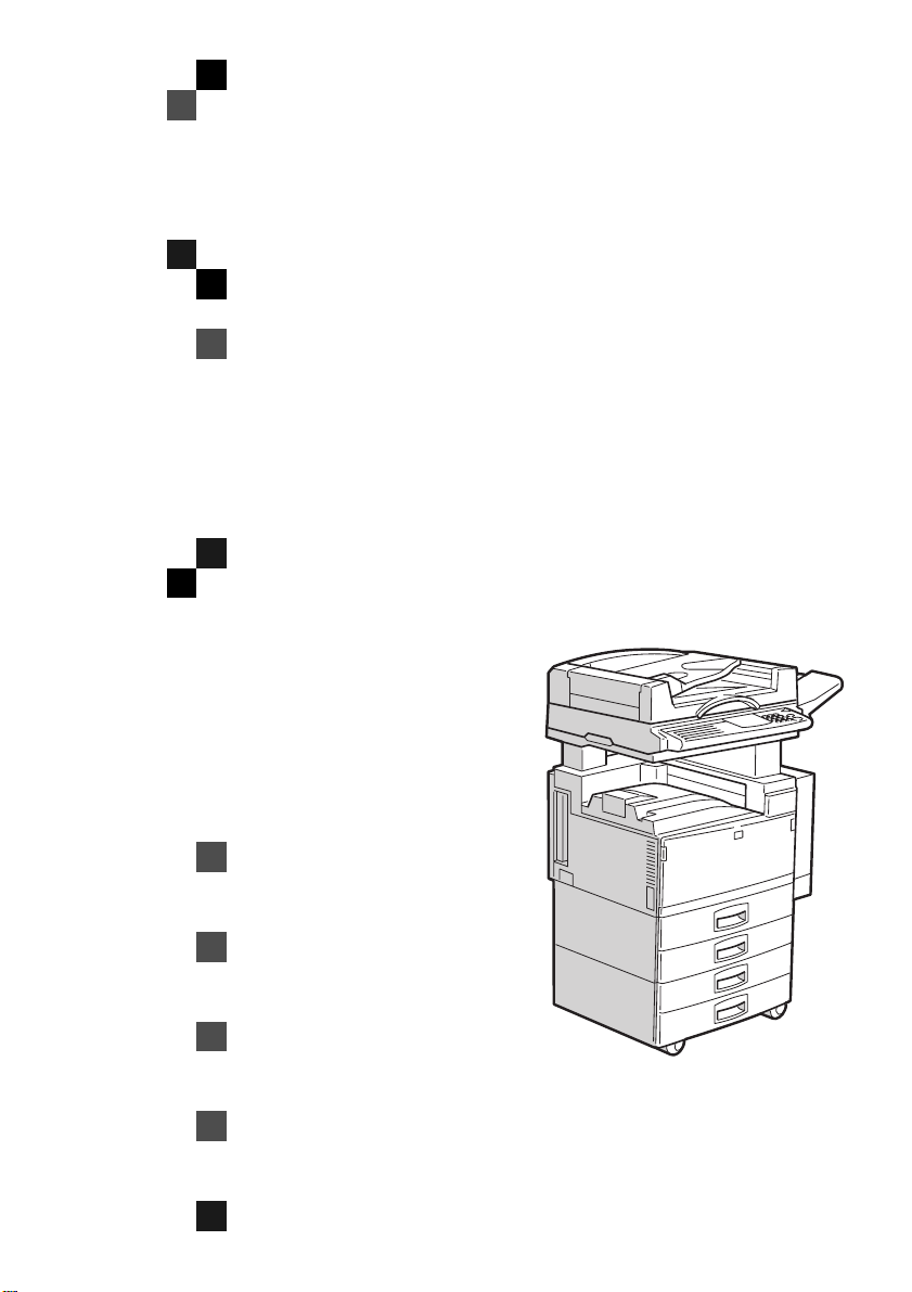
Scanner Option Type 450e
(Option)
OPERATING INSTRUCTIONS
SCANNER REFERENCE
ND0A0101
Read this manual carefully before you use this product a nd k eep it hand y f or fut ure
reference.
For safety, please follow the instructions in this manual.
Page 2

Scanner Option Type 450e (Option)
OPERATING INSTRUCTIONS
Printed in Japan
UE USA B359-8540
Page 3

Introduction
This manual contains detailed instructions on th e operation a nd maintena nce of this mach ine. To get
maximum versatility from this machine all operators sho uld carefu lly read and fo llow the inst ruction s in
this manual.
Please read the Safety Information in the “Copy Reference” before using this machine. It contains important information related to USER SAFETY and PREVENTING EQUIPMENT PROBLEMS.
Important
Parts of this manual are subject to change without prior notice. In no event will the company be liable
for direct, indirect, special, incidental, or consequ ential damages as a result of han dling or operating
the machine.
Trademarks
®
Microsoft
and Windows® are registered trademarks of Microsoft Corporation in the United States and/
or other countries.
®
Ethernet
is a registered trademark of Xerox Corporation.
Warning:
Use of controls or adjustment or performance of procedures other than those specified in this manual
might result in hazardous radiation exposure.
Notes:
Some illustrations might be slightly different from your machine.
Certain options might not be available in some countr ies. Fo r det ails, pleas e conta ct your lo cal deal er.
Page 4

Note to users in the United States of America
Notice:
This equipment has been tested and found to comply with the limits for a Class B digital device, pursuant to Part 15 of the FCC Rules. These limits are d esigned to provide rea sonable protection agains t
harmful interference in a residential installation. This equipment generates, uses and can radiate radio
frequency energy and, if not ins talled and us ed in accor dance with th e instruc tions, may ca use harmf ul
interference to radio communications. However, there is no guarantee that interference will not occur
in a particular installation. If this equipmen t does ca use harmful in terference to radio or television reception, which can be determined by turning the equipment off and on, the user is encouraged to try to
correct the interference by one more of the followin g measures:
Reorient or relocate the receiving antenna.
Increase the separation between the equipment and receiver.
Connect the equipment into an outlet on a circuit different from that to which the receiver is
connected.
Consult the dealer or an experienced radio /TV technician for help.
Warning
Changes or modifications not expressly approved by the party responsible for compliance co uld void
the user's authority to operate the equipment.
Caution
Properly shielded and grounded cables and connectors must be used for connections to host computer
(and/or peripheral) in order to meet FCC emission limits.
Declaration of conformity
Product Name: Scanner Option
Model Number: Type 450e
Responsible party: Ricoh Corporation
Address: 5 Dedrick Place, West Caldwell, NJ 07006
Telephone number: 973-882-2000
This device complies with part 15 of FCC Rules.
Operation is subject to the following two conditions:
1. This device may not cause harmful interference, and
2. this device must accept any interference received,
including interference that may cause undesired operation.
Note to users in Canada
Warning:
This Class B digital apparatus meets all requirements of the Canadian Interference-Causing Equipment Regulations.
Remarque concernant les utilisateurs au Canada
Avertissement:
Cet appareil numérique de la classe B respecte toutes les exigences du Règlement sur le matériel
brouilleur du Canada.
In accordance with IEC 60417, this machine uses the following symbols for the main power switch:
aaaa means POWER ON.
bbbb means POWER OFF.
Copyright © 2000
Page 5

Manuals for This Machine
There are five manuals that separately describe the operational procedures for
the operation and maintenance of the machine.
This manual, the Scanner Reference, contains detailed instructions for using this
machine as a scanner.
To ensure safe and efficient operation of the machine, all users should read and
follow the instructions contained in the following manuals.
❖❖❖❖
System Settings
Describes the procedures and functions for adjusting the settings and defaults
of this machine for the copier.
❖❖❖❖
Copy Reference
Describes the procedures and functions for using this machine as a copier.
❖❖❖❖
Scanner Reference
Describes the system settings, procedures and functions for using this machine as a scanner. (This Manual)
❖❖❖❖
ScanRouter Operating Instructions
Describes the procedures and provides necessary information about using
the machine with the Network TWAIN Scanner function.
❖❖❖❖
ScanRouter-Browser Operating Instructions
Describes the procedures and provides necessary information about using
ScanRouter-Browser.
i
Page 6

How to Read This Manual
R
R
Symbols
In this manual, the following symbols are used:
WARNING:
This symbol indicates a potentially hazardous situation that might result in
death or serious injury when you misuse the machine without following the instructions under this symbol. Be sure to read the instructions, all of which are described in the Safety Information in the “Copy Reference”.
CAUTION:
This symbol indicates a potentially hazardous situation that might result in minor or moderate injury or property damage that does not involve personal injury
when you misuse the machine without following the instructions under this
symbol. Be sure to read the instructions, all of which are described in the Safety
Information in the “Copy Reference”.
* The statements above are notes for your safety.
Important
If this instruction is not followed, paper might be misfed, originals might be
damaged, or data might be lost. Be sure to read this.
Preparation
This symbol indicates the prior knowledge or preparations required before operating.
Note
This symbol indicates precautions for operation, or actions to take after misoperation.
Limitation
This symbol indicates numerical limits, functions that cannot be used together,
or conditions in which a particular function cannot be used.
Reference
This symbol indicates a reference.
[]
Keys that appear on the machine's panel display.
{}
Keys built into the machine's operation panel.
ii
Page 7

TABLE OF CONTENTS
1.Preparation
Features...................................................................................................... 2
Network TWAIN Scanner.............................................................................. 2
Network Delivery Scanner....................................... ........ ....... ....................... 4
Confirming the Scanner Network Interface............................................. 6
Connecting to the Network....................................................................... 7
Indicators................................. ...................................................................... 7
2.Setting Up the Scanner
Setting Items.............................................................................................. 9
Setting Up the Network Environment.................................................... 11
Network Setting Items................................................................................. 13
Setting Up the Scanner........................................................................... 16
Scanner Setting Items................................................................................. 18
3.Installing the Driver
Features.................................................................................................... 21
Environments........................................................................................... 22
Installing/Uninstalling Type 270 TWAIN Driver Ver.2........................... 23
Using Windows 95/98 ................................................................................. 23
Using Windows NT 4.0................................................................................ 25
Using Windows NT 3.51.............................................................................. 26
4.Basic Operation
Using as a scanner.................................................................................. 29
Changing to Scanner Mode ........................................................................ 29
Interrupting Scanning.................................................................................. 29
Setting Originals on the Exposure Glass (Platen Glass)..................... 31
Setting Originals in the Document Feeder (ADF)................................. 32
1-sided Scanning ........................................................................................ 33
2-sided Scanning ........................................................................................ 34
5.Appendix
Troubleshooting...................................................................................... 35
Copier Error Messages........................................................................... 36
Image Data Setting Error Messages........................................................... 36
Copier Error Messages ............................................................................... 37
Network Delivery Scanner Error Messages ................................................ 38
iii
Page 8

Type 270 TWAIN Driver Ver.2 Error Messages..................................... 39
Image Data Setting Error Messages........................................................... 39
Scanning Operation Error Messages.......................................................... 39
Copier Error Messages ............................................................................... 40
Other Error Messages................................................................................. 41
Status Messages ..................................................................................... 42
Relationship Between Resolution and Scanning Area........................ 43
When Using DHCP................................................................................... 45
Supported Systems..................................................................................... 45
Configuring the Scanner with a Reserved IP Address................................ 45
Assigning an IP Address with ARP+PING ............................................ 46
Specifications.......................................................................................... 47
INDEX........................................................................................................ 48
iv
Page 9

1. Preparation
This machine can be used as a network scanner by installing Scanner Option
Type 450e. The network scanner has two functions: the “Network Delivery Scanner” and the “Network TWAIN Scanner”.
This chapter provides necessary information about the features and the best environment for this machine.
Note
❒ You can add the Network Delivery Scanner function using ScanRouter which
comes with the machine to deliver scanned images to clients on the network.
❒ This manual mainly explains how to use the Network TWAIN Scanner func-
tion. For more information about the operation and configuration of the Network Delivery Scanner function, see the “Operating Instructions” that come
with ScanRouter.
1
Page 10
Preparation
Features
1
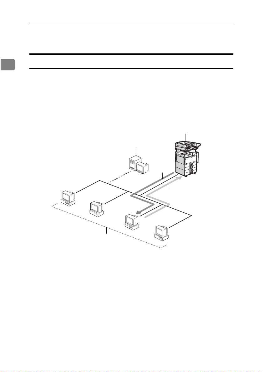
Network TWAIN Scanner
The Network TWAIN Scanner allows clients on the network to use the scanner
as if the scanner were connected directly to the clients.
The illustration shows the following procedure: client C sends a message to the
machine to scan the originals, and then the scanned image data is returned to client C.
1
2
5
4
A
B
3
C
D
1. scanner
2. ScanRouter Station
3. clients
2
ZATX500E
4. scanning command
5. scanned data
Page 11

Features
Note
❒ Confirm that the client computers and the scanner unit are on the same local
network segment. The client computers cannot be connected to the scanner
unit located on a different local network segment.
❒ To use the Network TWAIN Scanner to scan originals, follow these steps.
A Setting originals
Set originals on the exposure glass (platen glass) or in the document feeder
(ADF).
⇒ P.31 “Setting Originals on the Exposure Glass (Platen Glass)”
⇒ P.32 “Setting Originals in the Document Feeder (ADF)”
B Configuring the scanner settings from a network client
Start Type 270 TWAIN Driver Ver.2 from the application using the TWAIN
driver, and then configure the scanner settings.
C Starting the scan
Type 270 TWAIN Driver Ver.2 starts scanning.
1
3
Page 12
1
Preparation
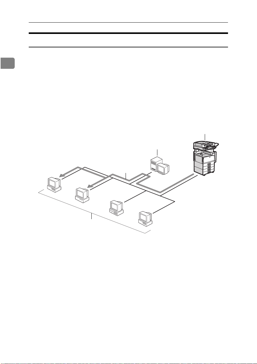
Network Delivery Scanner
The Network Delivery Scanner is made available when ScanRouter is installed.
You can deliver scanned data from the scanner to a selected client among preregistered clients.
It is also possible to deliver scanned data to multiple clients at the same time.
The following illustration shows how scanned data is delivered to clients A and
B at the same time.
1
2
4
A
B
3
1. scanner
2. ScanRouter Station
C
D
3. clients
4. scanned data
To deliver scanned data to a client using the Network Delivery Scanner, follow
the procedure below.
For more information about operating the Network Delivery Scanner, see the
“Operating Instructions” that come with ScanRouter.
4
ZATX510E
Page 13

Note
❒ The first four steps can be done in any order.
A Selecting the receiver
Use the operation panel to set the address of the client that will receive
scanned data.
B Selecting the sending client computer
Use the operation panel to set the address of the client that will deliver
scanned data.
C Configuring the scanner settings
Use the operation panel to configure the scanner settings.
D Setting originals
Set originals on the exposure glass (platen glass) or in the document feeder
(ADF).
⇒ P.31 “Setting Originals on the Exposure Glass (Platen Glass)”
⇒ P.32 “Setting Originals in the Document Feeder (ADF)”
E Starting the scan
Start the scan.
Features
1
5
Page 14
1
Preparation
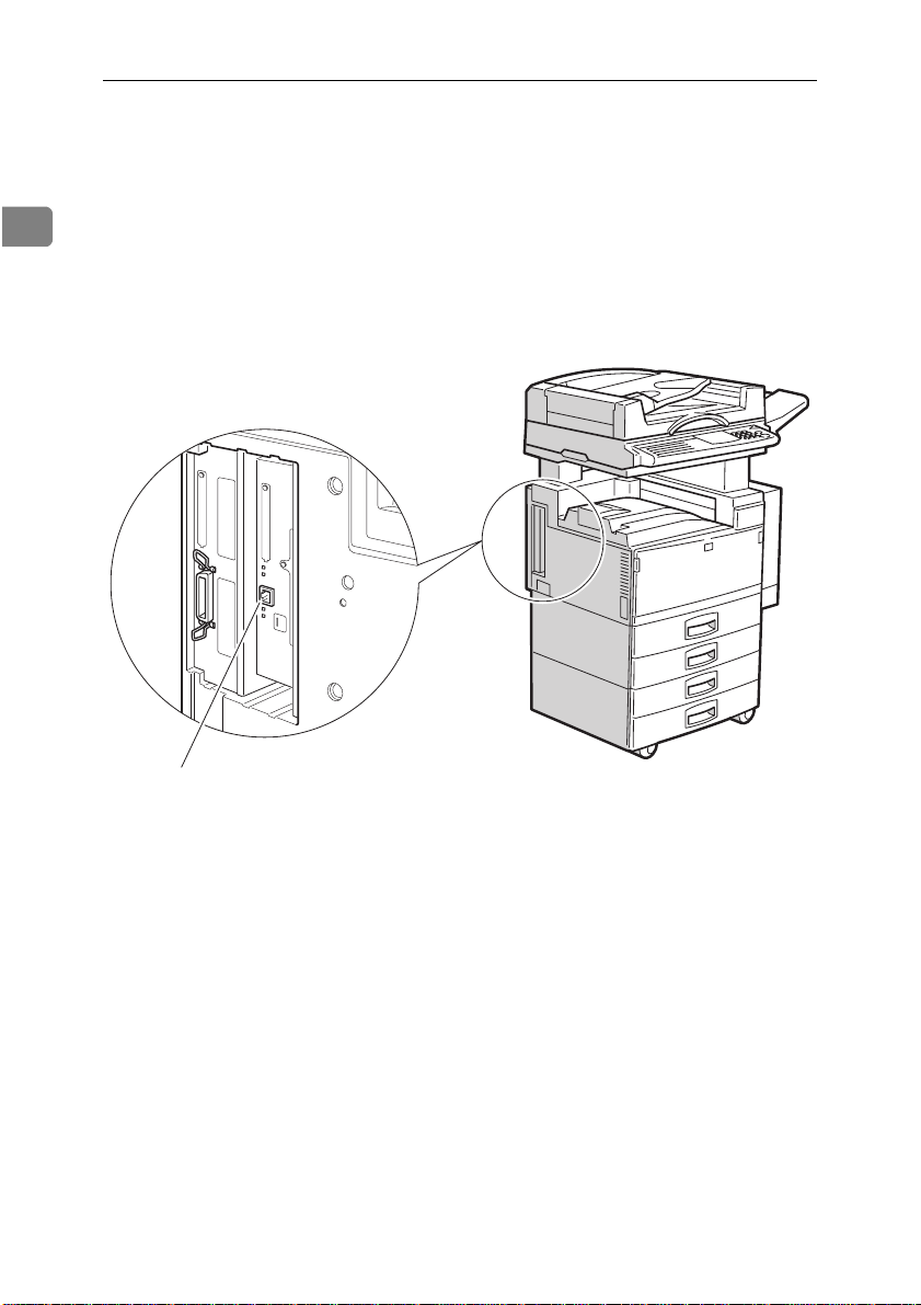
Confirming the Scanner Network Interface
The scanner unit is installed on the left side of the machine as shown in the illustration.
The network interface of this scanner unit supports 10BASE-T and 100BASE-TX
(one of which is detected automatically).
1
1. 10BASE-T/100BASE-TX port of
the scanner unit
Optional equipment is installed in this illustration.
6
TACH010E
Page 15
Connecting to the Network
1
2
3
4
ZATH520E
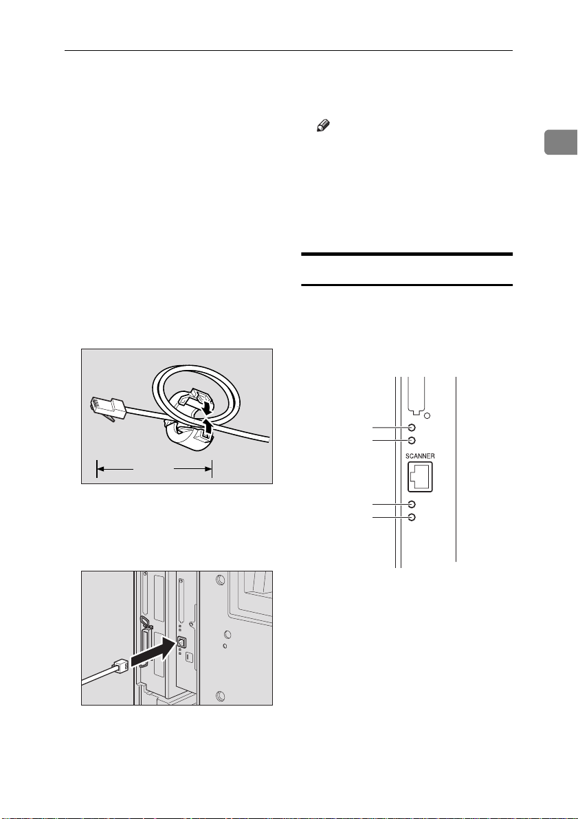
Connecting to the Network
This scanner unit and the network
are connected using 10BASE-T or
100BASE-TX network cable.
Confirm that the main power
A
switch is off.
Loop the network cable twice.
B
The loops should be about 15 cm
(6 inch) from the end of the cable
on the end closest to the connector.
Attach the ferrite core to the
C
loops.
A
A = 15 cm (6 inch)
ZATX520E
Note
❒ The default IP address is
"011.022.033.044". Change the IP
address in accordance with the
environment you are using. For
more information about changing the IP address, see P.11 “Set-
ting Up the Network Environment”.
Indicators
There are four LED indicators on the
scanner unit. They can be used to confirm that the board is working properly.
1
Connect the scanner unit to the
D
network hub using the network
cable.
1. Indicator (red)
Is on while the network is working.
2. Indicator (orange)
Is on while Network Interface Board is
working.
Turn on the main power switch.
E
TACH020E
3. Indicator (green)
Is on while using 100BASE-TX. Is off
while using 10BASE-T.
4. Indicator (green)
Is on while the machine is in a network
environment.
7
Page 16

1
Preparation
8
Page 17

2. Setting Up the Scanner
Setting Items
This chapter explains the settings necessary to use the machine as a network
scanner.
To use the machine as the Network TWAIN Scanner or the Network Delivery
Scanner, the following three initial settings are required: network settings, image data settings and scanner settings.
• ★ indicates the settings required to use the machine as a network scanner.
Confirm that all these settings are configured before using the machine.
• ✩ indicates the settings required depending on the environment. Configure
the settings appropriate to the environment you are using.
Network
Settings
Image Data
Settings
Items Default
Scanner IP Address 011.022.033.044
Subnet Mask 000.000.000.000
Gateway Address 000.000.000.000
Access Control (Access
Control Address)
Access Mask (Access Control Mask)
Network Boot NONE
Delivery Server Address
Mac Address
Density 4
Scan type Text (Black &
Resolution 100dpi
Scan size Auto Detect
*4
000.000.000.000
000.000.000.000
*3
000.000.000.000
—
White)
TWAIN
*1
Delivery
★★
✩✩
✩✩
✩
✩
✩✩
*2
★
★
★
★
★
9
Page 18

Setting Up the Scanner
2
Scanner
Settings
Items Default
Function Priority
*3
TWAIN connection time
*3
out.
Scanner Auto Clear Time
*3
Date -
Compression(Black &
Delivery
Off
Off
On
TWAIN
*1
Delivery
✩✩
*2
✩
✩
✩
✩
White)
Compression(Gray Scale) Standard
Delivery option Not Installed
*3
Auto Address Update
Measurement Unit
*1
Settings required for the Network TWAIN Scanner
*2
Settings required for the Network Delivery Scanner
*3
You cannot configure this setting if “Not Installed” is configured for “Delivery option” of the scanner settings.
*4
The setting value can be displayed, but not changed.
*3
On
mm
✩✩
★
★
★
Note
❒ This chapter explains the network settings and the scanner settings necessary
for using the Network TWAIN Scanner.
❒ To use the Network Delivery Scanner, the image data settings must be con-
figured. For more information about the image data settings, see the “Operating Instructions” that come with ScanRouter.
10
Page 19

Setting Up the Network Environment
Setting Up the Network Environment
This section explains how to set up
the network environment and configure essential settings. For more information about setting values, see P.13
“Network Setting Items”.
Important
❒ Consult the network administrator
for help with these settings.
A
Press {{{{
User Tools/Counter
Sort
Staple
Stack
1-Sided 2-Sided
2
1
1
Book 2-Sided
2
2-Sided 2-Sided
2
2
}}}}.
User Tools / Counter
PEN0200TN
The “User Tools Main Menu” appears.
Limitation
❒ While scanning, delivering,
printing or copying, pressing
{
User Tools/Counter
} does not
cause the message to change
to “User Tools Main Menu”.
Press {{{{5}}}} on the number keys.
B
The “Scanner Features” menu appears.
C
Press
[
Network
]
.
The following message appears.
Search for the desired menu with
D
[
]
[
↓↓↓↓
Next
or
↑↑↑↑
Prev.
]
.
The desired menu appears.
Note
❒ To cancel the current settings,
press
press
E
OK
[
Press
• If you press
[
PrevMenu
[
Exit
]
.
]
twice, and then
]
.
[
]
after selecting
OK
“2. Subnet Mask” in step D, the
following message appears.
When this occurs, you can
change the setting by entering
the desired numerical values.
2
ND2C0101
11
Page 20

Setting Up the Scanner
2
• If you press [OK] after selecting
“6. Network Boot” in step D, the
following message appears.
“*”(asterisk) is displayed with
the current settings. When this
occurs, you can change the setting by selecting the items.
Start settings.
F
• When entering numerical values, use the number keys. If you
press {
cal values, you can continue to
the next column. < or > can be
also available to change the input position.
• When selecting items, press [↑↑↑↑]
or [↓↓↓↓] to navigate through the
items to be configured on the
panel display.
Note
❒ For more information about the
setting items, see P.13 “Network
Setting Items”.
❒ To cancel the current settings,
press [
turn to their previous values,
and the previous screen appears.
} after entering numeri-
#
]. The settings re-
Cancel
Press [
H
I
J
PrevMenu
The message displayed in step C
appears.
Note
❒ From this screen, you can also
make the image data settings
and the scanner settings.
Press [
PrevMenu
The message displayed in step A
appears.
Press [
Exit
The changed settings are saved,
and the message before the settings were made appears.
Important
❒ After pressing [
off the machine until the main
menu is displayed, or the settings will not be applied.
Note
❒ The changed settings cannot be
saved until you press [
These settings also cannot be
saved if the power is turned off
before [
❒ If you press {
while navigating the message
screens, changed settings will
not be saved.
].
].
].
Exit
] is pressed.
Exit
User Tools/Counter
], do not turn
Exit
].
}
12
Press [OK].
G
Changed values are saved and the
message displayed in step D appears.
Note
❒ From this screen, you can also
configure other network settings.
Page 21

Network Setting Items
Required network settings are as follows. Make settings appropriate to
the network environment.
Items Default
1. Scanner IP
Address
2. Subnet Mask 000.000.
3. Gateway
Address
4. Access Control
(Access Control
Address)
5. Access Mask
(Access Control
Mask)
6. Network Boot NONE
7. Delivery Server
*3
Address
8.Mac Address
*1
Settings required for the Network
TWAIN Scanner
*2
Settings required for the Network Delivery Scanner
*3
You cannot configure this setting if
011.022.
033.044
000.000
000.000.
000.000
000.000.
000.000
000.000.
000.000
000.000.
000.000
*4
"Not Installed" is configured for "7.
Delivery option" of the scanner settings.
*4
The setting value can be displayed,
but not changed.
TWAIN
-
Delivery
*1
★★
✩✩
✩✩
✩
✩
✩✩
*2
★
Setting Up the Network Environment
❖❖❖❖
Scanner IP Address
This is the IP address of this scanner on the network. It is essential
that the IP address be entered.
Set the address as follows:
xxx.xxx.xxx.xxx (xxx: for any numerical value from 0–255)
Note
Do not assign the same IP ad-
❒
2
dress to two or more machines
on the same network. If two or
more machines on the network
have the same IP address, the
machine will not work. To confirm the address, contact the
network administrator.
❖❖❖❖
Subnet Mask
This sets a part of the IP address as
the network address. Use a subnet
mask if the network uses subnets.
Set the mask values as follows:
xxx.xxx.xxx.xxx (xxx: for any numerical value from 0–255)
Note
If you do not know the mask
❒
values, use the default setting.
❖❖❖❖
Gateway Address
This is the address of the router or
host computer used as the gateway. Set it up if you want to use
the machine from a client in a different network. Set the mask values as follows: xxx.xxx.xxx.xxx
(xxx: for any numerical value from
0–255)
Note
If you do not know the gateway
❒
address, use the default setting.
13
Page 22

2
Setting Up the Scanner
❖❖❖❖
Access Control Address and Access
Control Mask
The access control address and the
access control mask are used to
limit the clients that have access to
the scanner on the basis of their IP
addresses. They are inseparable,
and therefore, if one is configured,
the other must also be configured
at the same time.
• The access control address uses
an IP address to set the clients
that can access the scanner.
• The access control mask is used
with the access control address
to set a range of IP addresses
that can access the scanner.
Set the address as follows:
xxx.xxx.xxx.xxx (xxx: for any numerical vale from 0–255)
Note
If you do not want to limit ac-
❒
cess to the machine, use the default settings.
When the access control ad-
❒
dress settings coincide with the
masked result of the IP address
of the computer, scanning jobs
from that client's IP address can
be accepted by the network interface.
For example, if you assign
❒
192.168.15.16 as the access control address to the Network Interface Board, the combination
of the access control mask and
IP Addresses that can have access are as follows. (xxx: for any
numerical value from 0–255)
Access Control
Mask
IP Addresses
that have access
000.000.000.000 xxx.xxx.xxx.xxx
255.000.000.000 192.xxx.xxx.xxx
255.255.000.000 192.168.xxx.xxx
255.255.255.000 192.168. 15.xxx
255.255.255.255 192.168. 15. 16
❖❖❖❖
Network Boot
This selects the way in which the
client can set the IP address of the
scanner.
The default setting is “NONE”. To
change it, consult the network administrator, and make new settings appropriate for the network
environment. The settings you can
select are as follows.
Menu Items on
the Panel
Display
NONE
(Default Setting)
ARP&PING
RARP&TFTP
BOOTP
RARP&BOOTP
ARP&RARP
ARP&BOOTP
ARP&RARP&
BOOTP
DHCP
*1
ARP+PING
*2
RARP+TFTP
*3
BOOTP
*4
DHCP
Available Method
AR
RA
*1
✩
✩✩
✩✩
✩✩✩
BO
*2
*3
✩
✩
✩✩
DH
*4
✩
14
Page 23

Note
❒ If you want to use “RARP +
TFTP”, “BOOTP” or “DHCP”,
you must configure the server.
❒ When selecting DHCP, assign
the scanner a fixed IP address.
⇒ P.45 “When Using DHCP”
❖❖❖❖
Delivery Server Address
This is the server IP address used to
deliver the scanned originals to a client on the network. Set this address
when you use the machine as a Network Delivery Scanner. Set the address as follows: xxx.xxx.xxx.xxx
(xxx: for any numerical value from
0–255)
Note
❒ To get the delivery server IP ad-
dress for the scanner, contact
the network administrator.
❖❖❖❖
Mac Address
You can confirm the MAC address
of the scanner unit installed in the
machine. The MAC address has already been assigned for each machine, and therefore, cannot be
changed.
⇒ P.45 “When Using DHCP”
⇒ P.46 “Assigning an IP Address
with ARP+PING”
Setting Up the Network Environment
2
15
Page 24

Setting Up the Scanner
Setting Up the Scanner
2
This section explains how to set up
the scanner and how to configure essential settings. For more information
about the setting values, see P.18
“Scanner Setting Items”.
A
Press {{{{
User Tools/Counter
Sort
Staple
Stack
1-Sided 2-Sided
2
1
1
Book 2-Sided
2
2-Sided 2-Sided
2
2
}}}}.
User Tools / Counter
PEN0200TN
The “User Tools Main Menu” appears.
Limitation
❒ When scanning, delivering,
printing or copying, pressing
{
User Tools/Counter
} does not
cause the message to change to
“User Tools Main Menu”.
Press {{{{5}}}} on the number keys.
B
The “Scanner Features” menu appears.
The following message appears.
Search for the desired menu with
D
]
[
[
↓↓↓↓
Next
or
↑↑↑↑
Prev.
]
.
The desired menu appears.
Note
❒ To cancel the current settings,
press
press
E
OK
[
Press
• If you press
[
PrevMenu
[
Exit
]
.
]
twice, and then
]
.
[
]
after selecting
OK
“4. Date” in step D, the following message appears. When this
occurs, you can change the setting by entering the desired numerical values.
[
• If you press
]
after selecting
OK
“5. Compression(Black &
White)” in step D, the following
message appears. “*”(asterisk)
is displayed with the current
settings. When this occurs, you
can change the settings of the
items.
16
C
Press
[
Config.
]
.
ND2C0103
Page 25

Setting Up the Scanner
Start settings.
F
• When entering numerical values, use the number keys. If you
press {
cal values, you can continue to
the next column. < or > can be
also used to change the input
position.
• When selecting items, press [↑↑↑↑]
or [↓↓↓↓] to select items indicated
on the panel.
Note
❒ For more information about the
setting items, see P.18 “Scanner
Setting Items”.
❒ To cancel the current settings,
press [
turn to the previous values, and
the previous screen appears.
Press [OK].
G
Changed values are saved and the
message displayed in step D appears.
Note
❒ From this screen, you can also
configure other scanner settings.
} after entering numeri-
#
]. The settings re-
Cancel
Press [
J
The changed settings are saved,
and the message before the settings were made appears.
Important
❒ After pressing [
off the machine until the main
menu is displayed, or the settings will not be applied.
Note
❒ The changed settings cannot be
saved until you press [
These settings also cannot be
saved if the power is turned off
before [
❒ If you press {
while navigating the message
screens, changed settings will
not be saved.
Exit
].
Exit
] is pressed.
Exit
User Tools/Counter
], do not turn
Exit
2
].
}
Press [
H
I
PrevMenu
The message displayed in step
appears.
Note
❒ From this screen, you can con-
figure the network settings and
the image data settings.
Press [
PrevMenu
The message displayed in step
appears.
].
].
C
A
17
Page 26

Setting Up the Scanner
2
Scanner Setting Items
Required scanner settings are as follows. Configure settings appropriate
to the network environment.
Items Default
1. Function
*3
Priority
2. TWAIN connec-
tion time out.
3. Scanner Auto
Clear Time
4. Date
5. Compression
(Black & White)
6. Compression
(Gray Scale)
7. Delivery option Not
8. Auto Address
*3
Update
9. Measurement
*3
Unit
*1
Setting required for the Network
TWAIN Scanner
*2
Setting required for the Network Delivery Scanner
*3
You cannot configure this setting if
Delivery
Off
*3
Off
*3
On
Standard
Installed
Off
mm
"Not Installed" is configured for the
"7. Delivery option" of the scanner settings.
❖❖❖❖
Function Priority
Select "TWAIN" or "Delivery" to
use the Network TWAIN Scanner
mode or the Network Delivery
Scanner mode by pressing {
} on the operation panel. The
ner
default setting is "Delivery".
TWAIN
Delivery
*1
✩✩
✩✩
*2
✩
✩
✩
✩
★
★
★
Scan-
Note
When selecting “TWAIN” and
❒
pressing {
Scanner
}, the mode
switches to the Network
TWAIN Scanner mode. You can
switch to the Network Delivery
Scanner mode by pressing
]
.
cel
When Selecting “Delivery” and
❒
pressing {
Scanner
}, the mode
[
Can-
switches to the Network Delivery Scanner mode. Remember
that you cannot do the opposite
(that is, switch from the Network Delivery Scanner mode to
the Network TWAIN Scanner
mode.) If you want to use the
machine as the Network
TWAIN Scanner, access the machine from the computer which
will scan the originals.
Important
After changing settings, turn
❒
the main power switch off and
on. If this is not done, the settings will not be applied.
❖❖❖❖
TWAIN connection time out.
You can set the duration to switch
the mode from “Delivery” to
“TWAIN” while using the machine as the Network Delivery
Scanner when other clients are accessing the machine to scan originals as the Network TWAIN
Scanner.
• If you select “Off”, you can
switch to the Network TWAIN
Scanner immediately.
• When selecting “On”, input the
disconnect duration time (3-30
seconds) with the number keys.
The default setting is “Off”.
18
Page 27

❖❖❖❖
Scanner Auto Clear Time
When selecting a receiver, a sender
or image data settings using the
Network Delivery Scanner mode,
if you do not input anything for a
certain amount of time, the command you have made will be
cleared.
• When selecting "On", use the
number keys to enter the length
of time (10-999 seconds) the machine waits before clearing the
settings.
• If "Off" is selected, the settings
will not be cleared.
The default setting is "Off".
❖❖❖❖
Date
Set the current date and time. Enter the information in the following sequence with the number
keys: year (four digits), month,
day, hour (24 hour style), minute
and second.
Note
The date set here is for clients
❒
who use the machine as the Network Delivery Scanner to see
the length of time that is needed
to scan originals.
Setting Up the Scanner
The amount of time required to
❒
send the data depends on the
amount of data and the network
conditions.
❖❖❖❖
Compression(Gray Scale)
You can configure the amount of
compression applied to the
scanned gray scale data. Compression allows the data to be sent to
the personal computer in less time.
The default setting is “Standard”.
Note
Compression is for reducing the
❒
amount of time used to send the
image to the computer, and not
for compressing the scanned
original image.
Lower compression rates re-
❒
quire more time to transfer,
from lower to highest, "Low"
"Standard" "High" and "Off".
The amount of time required to
❒
send the data depends on the
amount of data and the network
conditions.
2
❖❖❖❖
Compression(Black & White)
You can configure whether or not
the transmitted data is to the be
compressed. Compression allows
data to be sent to the computer in
less time. Select “On” or “Off”. The
default setting is “On”.
Note
Compression is for reducing the
❒
amount of time used to deliver
the image to the computer, and
not for compressing the
scanned image.
19
Page 28

2
Setting Up the Scanner
❖❖❖❖
Delivery option
This setting is necessary to use the
machine as the Network Delivery
Scanner with ScanRouter installed.
When you set “Delivery option” to
"Installed", the following settings
are available. When you set the
“Delivery option” to "Not Installed", these settings are not
available.
• Network Settings “7. Delivery
Server Address”
• Scanner Settings “1. Function
Priority”, “2. TWAIN connection time out.”, “3. Scanner
Auto Clear Time”, “8. Auto Address Update”, “9. Measurement Unit”.
The default setting is “Not Installed”.
Important
After changing the settings,
❒
turn the main power switch off
and on. If this is not done, the
new settings will not be applied.
❖❖❖❖
Measurement Unit
You can set the unit of measurement that is shown on the operation panel when scanning originals
by selecting the area to be scanned
with the Network Delivery Scanner mode.
Select "mm" or "inch".
The default setting is "mm".
20
❖❖❖❖
Auto Address Update
When using the machine as the
Network Delivery Scanner, you
can use this function to automatically update the address book (the
lists of addresses and senders).
• When selecting "On", pressing
[
Address
Delivery Scanner mode, the address saved in the machine is
compared with the one saved in
the ScanRouter Station, and
then it will be updated.
• When selecting "Off", only
when you turn on the main
power switch, the address is updated.
The default setting is "On".
]
while in the Network
Page 29

3. Installing the Driver
Features
The drivers (provided on the CD-ROM labeled “Type270 TWAIN Driver”) allow you to use this machine with the installed scanner unit through the network.
To use the machine as a network scanner, Type 270 TWAIN Driver Ver.2 is required. A Web Browser used for monitoring the scanner unit on the network is
also included on the CD-ROM.
This chapter provides necessary information about the features and environment required to use and install/uninstall the driver. This chapter also includes
information about using a Web Browser to monitor the scanner on a network.
Type 270 TWAIN Driver Ver.2
This driver allows you to scan originals with a scanner. Be sure to install this
driver before using the scanner unit.
The driver can also provides the following functions: compounding written
rows, such as those of date and page numbers, and adjusting the slant of letters.
⇒ P.23 “Installing/Uninstalling Type 270 TWAIN Driver Ver.2”
Note
❒ Type 270 TWAIN Driver Ver.2 is included on the CD-ROM in the following
directory:
\DRIVER\TWAIN\
Configuring Network Interface Board with a Web Browser
You can use a Web Browser to view the printer and scanner status through the
network. If the computer is connected to the network and is configured to use a
Web Browser, you can use this function regardless of the computer's OS. You do
not need to install any additional applications to use this function.
Note
❒ For more information about a Web Browser, see the Online Help that is in-
cluded on the CD-ROM in the following directory:
\HELP\WSMHLP\
21
Page 30

3
Installing the Driv er
Environments
To use Type 270 TWAIN Driver Ver.2, the following hardware and software environments are required.
❖❖❖❖
Personal Computer
75 MHz or faster Intel Pentium CPU (200 MHz or faster recommended)
The computer must have a CD-ROM drive. (The driver is provided on a CDROM.)
❖❖❖❖
OS
Windows 95/98 or Windows NT 4.0/3.51
Note
Windows 3.1x is not supported.
❒
❖❖❖❖
Memory
Windows 95/98: 16 MB or more (48 MB or more recommended)
Windows NT 4.0/3.51: 24 MB or more (64 MB or more recommended)
❖❖❖❖
Display
Requires SVGA (800×600) supporting 256 colors or more.
❖❖❖❖
Hard Disk
100 MB of hard disk space (100 MB or more recommended) are required for
the installation, save and preview image files.
22
❖❖❖❖
Ethernet Board
It must be compatible with Windows 95/98 or Windows NT 4.0/3.51 environments.
Note
The Ethernet board does not work if it is not recognized in the Windows
❒
95/98 or Windows NT 4.0/3.51 environments.
❖❖❖❖
Ethernet Cable
Use category 5 STP cabling with an RJ-45 connector.
❖❖❖❖
Network Protocol
TCP/IP
❖❖❖❖
TWAIN Compliant Application
An application compliant to TWAIN 1.6 or later must be installed.
Note
If you are not sure that the application you are using is compliant to
❒
TWAIN 1.6 or later, contact the manufacturer of the application.
Page 31

Installing/Uninstalling Type 270 TWAIN Driver Ver.2
Installing/Uninstalling Type 270 TWAIN
Driver Ver.2
To use this scanner unit, Type 270
TWAIN Driver Ver.2 must be installed. Installation differs depending
on Windows 95/98, Windows NT 4.0
or Windows NT 3.51. Install the driver in accordance with the OS you are
using.
When you reinstall Type 270 TWAIN
Driver Ver.2, or when it becomes unnecessary, uninstall the driver in accordance with the OS you are using.
Important
❒ Before starting this installation,
close all documents and applications. In a network environment,
confirm that users who are logged
on are disconnected. Be sure to do
this when it will create the least interference with other users.
❒ After installing the driver, you
must restart the computer.
❒ If Type 450 TWAIN Driver (other
products) is installed, uninstall it
first, and then install Type 270
TWAIN Driver Ver.2.
Using Windows 95/98
Preparation
Before installation, confirm that
the computer you are using is configured to use the TCP/IP protocol, by selecting
[
Network
]
from
[
Configuration
[
Control Panel
Installing
When using Windows 95/98, follow
these steps.
]
in
]
.
Close all the applications that are
A
currently running.
Insert the CD-ROM into the CD-
B
ROM drive.
A setup program starts automatically and the
appears.
Reference
If the setup program does not
start automatically, see P.24
“Starting the Setup Program”.
Read the message on the screen
C
carefully, and then click
[
Software License Agreement
pears.
Read the message on the screen
D
carefully. If you agree, click
[
Select Program Folder
Read the message on the screen
E
carefully. If you agree, click
]
[
.
Next
Usually, you do not need to
change the program folder.
Installation starts, and
]
appears when it is complet-
plete
ed.
Note
❒ During installation, if the dialog
box appears asking you to confirm that you want to rewrite
the pre-installed files, click
[
Yes
Confirm the message on the
F
screen, and then click
[
Select
puter now.
[
welcome
]
.
Yes, I want to restart my com-
]
.
]
dialog box
[
Next
]
appears.
[
Setup Com-
[
Finish
]
.
]
ap-
[
Yes
]
.
3
]
.
23
Page 32

Installing the Driv er
3
Note
❒ If the screen message asking if
you want to restart the computer does not appear in step F,
[
Finish
]
.
]
.
click
❒ When restarting Windows by
installing this driver, the message of “ WINASPI has been replaced the old version” might
be displayed. In this case, click
[
Ignore
Starting the Setup Program
If the setup program does not start
automatically after inserting the CDROM into the CD-ROM drive, follow
these steps.
Double-click the
A
icon, and then double-click
]
trol Panel
Double-click
B
grams
[
Add/Remove Program Properties
pears.
Click
C
click
[
Setup
[
Install Programs From Floppy Disk or
CD-ROM
Click
D
Type the name of the CD-ROM
E
drive in the command line, followed by "\DRIVER\TWAIN\
OTHERS\SETUP.EXE" (do not
include the quotation marks), and
then click
❒
Installation starts.
.
]
.
[
Install/Uninstall
[
]
(for Windows 98) or
Install
]
(for Windows 95).
]
appears.
]
[
.
Next
[
OK
Note
An example would be "D:\DRIVER\
TWAIN\OTHERS\SETUP.EXE"
when the drive letter is "D".
[
My Computer
[
Add/Remove Pro-
]
.
24
[
Con-
]
ap-
]
, and then
When Finishing Installation
After installation, "Type 270 TWAIN
Driver Ver.2", "Help Files" and "Readme.txt" are registered.
❖❖❖❖
Help Files
“Help Files” is a help system that
contains information about the operational process to scan an image
and configuring the image data
settings using Type 270 TWAIN
Driver Ver.2.
❖❖❖❖
Readme.txt
“Readme.txt” contains information about using Type 270 TWAIN
Driver Ver.2. Be sure to read it before using them.
]
Uninstalling
When Type 270 TWAIN Driver Ver.2
is no longer needed, uninstall it. You
can delete Type 270 TWAIN Driver
Ver.2 and other related files from the
hard disk. When reinstalling Type
270 TWAIN Driver Ver.2, uninstall it
first, and then reinstall it.
Note
❒ When uninstalling, the setting val-
ues file is not deleted.
Double-click the
A
icon, and then double-click
]
trol Panel
Double-click
B
grams
The
ties
Click
C
and click
A dialog box appears to confirm
cancellation.
.
]
.
[
Add/Remove Program Proper-
]
dialog box appears.
[
Type 270 TWAIN Driver Ver.2
[
Add/Remove
[
My Computer
[
Add/Remove Pro-
]
[
Con-
]
]
.
Page 33

Installing/Uninstalling Type 270 TWAIN Driver Ver.2
Read the message on the screen
D
carefully. If you agree, click [
Uninstallation starts.
When [
E
played below the dialog box,
click [
The dialog box closes.
Uninstall successfully
].
OK
Yes
] is dis-
Using Windows NT 4.0
Preparation
Before installation, confirm that
the computer you are using is configured to use the TCP/IP proto-
col, by selecting [
[
Network
Note
❒ To install the Type 270 TWAIN
Driver Ver.2, you must be logged
on as a member of the Administrators group.
Installing
Close all the applications that are
A
currently running.
Insert the CD-ROM into the CD-
B
ROM drive.
A setup program starts automati-
cally and the [
appears.
Read the message on the screen
C
carefully. If you agree, click
[
Next
[
Software License Agreement
pears.
] from [
Reference
If the setup program does not
start automatically, see P.24
“Starting the Setup Program”.
].
Protocols
Control Panel
welcome
] dialog box
] in
].
] ap-
Read the message on the screen
D
].
carefully. If you agree, click [
[
Select Program Folder
Read the message on the screen
E
carefully. If you agree, click
[
].
Next
Usually, you do not need to
change the program folder.
Installation starts, and [
] is displayed when it is com-
plete
pleted.
Confirm the message on the
F
screen, and then click [
Select [
Yes, I want to rest art my com-
puter now.
❒ If the screen message asking if
When Finishing Installation
After installation, "Type 270 TWAIN
Driver Ver.2", "Help Files" and "Readme.txt" are registered.
❖❖❖❖
Help Files
“Help Files” is a help system that
contains information about the operational process to scan an image
and configuring the image data
settings using Type 270 TWAIN
Driver Ver.2.
❖❖❖❖
Readme.txt
“Readme.txt” contains information about using Type 270 TWAIN
Driver Ver.2. Be sure to read it before using them.
].
Note
you want to restart the computer does not appear in step F,
click [
Finish
] appears.
].
Yes
Setup Com-
].
Finish
].
3
25
Page 34

Installing the Driv er
3
Uninstalling
When Type 270 TWAIN Driver Ver.2
is no longer needed, uninstall it. You
can delete Type 270 TWAIN Driver
Ver.2 and other related files from the
hard disk. When reinstalling Type
270 TWAIN Driver Ver.2, uninstall it
first, and then reinstall it.
Note
❒ When uninstalling, the setting val-
ues file is not deleted.
Double-click the
A
icon, and then double-click
]
trol Panel
Double-click
B
grams
[
Add/Remove Program Properties
pears.
Click
C
and then click
A dialog box appears to confirm
cancellation.
Read the message on the screen
D
carefully. If you agree, click
Uninstallation starts.
When
E
dicated below the dialog box,
click
The dialog box closes.
.
]
.
[
Type 270 TWAIN Driver Ver.2
[
Uninstall successfully
[
]
.
OK
[
My Computer
[
[
Add/Remove Pro-
[
Add/Remove
]
.
[
]
is in-
Con-
]
ap-
Yes
Using Windows NT 3.51
Preparation
Before installation, confirm that
the computer you are using is configured to use the TCP/IP protocol, by selecting
[
in
Network
Note
❒ To install the Type 270 TWAIN
Driver Ver.2, you must be logged
]
]
]
.
on as a member of the Administrators group.
Installing
Close all the applications that are
A
currently running.
Insert the CD-ROM into the CD-
B
ROM drive.
[
Open
C
D
E
File Manager
From the file menu, click
]
[
appears.
Run
Type the name of the CD-ROM
drive in the command line, followed by "\DRIVER\TWAIN\
OTHERS\SETUP.EXE" (do not
include the quotation marks), and
then click
Note
❒
An example would be "D:\DRIVER\
TWAIN\OTHERS\SETUP.EXE"
when the drive letter is "D".
[
The
welcome
[
Network Settings
]
[
from
Control Panel
]
.
]
[
.
OK
]
dialog box appears.
[
Run...
]
]
.
]
.
26
Read the message on the screen
F
carefully, and then press
[
Software License Agreement
pears.
[
Next
]
]
ap-
.
Page 35

Read the message on the screen
G
carefully. If you agree, click [
[
Select Program Folder
Read the message on the screen
H
carefully. If you agree, click
[
].
Next
Usually, you do not need to
change the program folder.
Installation starts, and [
] is indicated when it is com-
plete
pleted.
Confirm the message on the
I
screen, and then click [
Select [
Yes, I want to restart my com-
puter now.
❒ If the screen message asking if
].
Note
you want to restart the computer does not appear in step I,
click [
Finish
] appears.
Setup Com-
Finish
].
].
Yes
Installing/Uninstalling Type 270 TWAIN Driver Ver.2
Uninstalling
].
When Type 270 TWAIN Driver Ver.2
is no longer needed, uninstall it. You
can delete Type 270 TWAIN Driver
Ver.2 and other related files from the
hard disk. When reinstalling Type
270 TWAIN Driver Ver.2, uninstall it
first, and then reinstall it.
Note
❒ When uninstalling, the setting val-
ues file is not deleted.
Double-click the [
A
from the Type 270 TWAIN Driver
Ver.2 group in the program manager.
From now, follow the instructions
B
displayed on the screen.
Uninstall
3
] icon
When Finishing Installation
After installation, "Type 270 TWAIN
Driver Ver.2", "Help Files", "Readme.txt" and “Uninstall” are registered.
❖❖❖❖
Help Files
“Help Files” is a help system that
contains information about the operational process to scan an image
and configuring the image data
settings using Type 270 TWAIN
Driver Ver.2.
❖❖❖❖
Readme.txt
“Readme.txt” contains information about using Type 270 TWAIN
Driver Ver.2. Be sure to read it before using them.
❖❖❖❖
Uninstall
Use “Uninstall” to uninstall Type
270 TWAIN Driver Ver.2.
27
Page 36

3
Installing the Driv er
28
Page 37

4. Basic Operation
Using as a scanner
Changing to Scanner Mode
This scanner unit has two scanner
functions: the "Network TWAIN
Scanner" and the "Network Delivery
Scanner".
Reference
To configure the function priority,
see P.18 “Scanner Setting Items”.
Limitation
❒ In the following cases, the machine
cannot be used as a scanner.
• While scanning originals for
copying
• While scanning a fax message
for transmission
• During immediate fax transmission
Using the Network TWAIN Scanner
Set originals.
A
Configure the scan options using
B
the computer.
Start the scan.
C
Reference
For more information about using the Network TWAIN Scanner, see Type 270 TWAIN
Driver Ver.2 help.
Using the Network Delivery Scanner
Press {{{{
A
B
C
D
Scanner
The screen for the scanner mode
appears.
Set originals.
Set the scan options, an address
and a sender.
Press {{{{
Start
Reference
For more information about using the Network Delivery Scanner, see the “Operating
Instructions” that come with
ScanRouter.
}}}}.
}}}}.
Interrupting Scanning
If you want to scan while copying or
faxing, follow the procedure below.
Scanning while copying
Usually, you cannot use this machine
as a scanner until it finishes copying.
Preparation
Select “06.Function Switch” of the
“System Settings” menu to set “Instant”. For more information about
how to access this menu, see the
“System Settings”.
Press {{{{
A
Clear/Stop
Copying is interrupted.
}}}}.
29
Page 38

Basic Operation
Remove the originals.
B
Press {{{{
C
Start the scan.
D
Note
❒ When the scan is completed,
press {
ing.
Scanning while scanning a fax message
for memory transmission
Reset
Copy
}}}}.
} and restart copy-
Scanning while doing an Immediate Fax
Transmission
Usually, you cannot use the scanner
function while an immediate fax
transmission is in progress.
Preparation
Select “06.Function Switch” of the
“System Settings” menu to set “Instant”. For more information about
how to access this menu, see the
“System Settings”.
4
Usually, you cannot use the scanner
function until scanning a fax message
for memory transmission is completed.
Preparation
Select “06.Function Switch” of the
“System Settings” menu to set “Instant”. For more information about
how to access this menu, see the
“System Settings”.
Press {{{{
A
B
C
Clear/Stop
The fax message scan is interrupted.
Note
❒ While using the quick memory
delivery, previously scanned
originals will be delivered.
Remove the originals.
Start the scan.
Note
❒ When the scan is completed,
press {
}}}}.
} and restart faxing.
Fax
Press {{{{
A
B
C
Scanning while printing
You can scan without interrupting
printing.
Clear/Stop
The immediate fax transmission is
interrupted.
Note
❒ Previously scanned originals
will be delivered.
Remove the originals.
Start the scan.
Note
❒ When the scan is completed,
press {
}}}}.
} and restart faxing.
Fax
30
Page 39

Setting Originals on the Exposure Glass (Platen Glass)
Setting Originals on the Exposure Glass
(Platen Glass)
The exposure glass (platen glass) can be used when scanning originals that cannot
be set in the document feeder (ADF), such as books or originals that have been
pasted together. These types of originals will be referred to as “book originals”.
Follow the procedure below to set originals on the exposure glass (platen glass).
Lift the platen cover or the document feeder (ADF), and place the original
A
face down on the exposure glass (platen glass).
Align the original with the reference mark.
1
TACY010E
1. Reference mark
Important
❒ Set the original after correction fluid and ink has completely dried. Not
taking this precaution could mark the exposure glass (platen glass) and
cause marks to be copied.
Note
❒ Set the original in the direction shown in the illustration. The direction of
resulting scan is as follows.
1
4
1. Reference mark
Lower the platen cover or the document feeder (ADF).
B
TACY020E
31
Page 40

4
Basic Operation
Setting Originals in the Document Feeder (ADF)
You can set several pages of originals in the document feeder (ADF) at a time.
Only originals that consist of separate sheets of paper can be set in the document
feeder (ADF); these originals will be called “sheet originals”. It is possible to
copy not only one side but both sides of originals that are set in the document
feeder (ADF).
Note
❒ The document feeder (ADF) is optional. Preparation is required to use it.
❖❖❖❖
Non-recommended originals for the document feeder
For more information about recommended and non-recommended originals
for the document feeder (ADF), see the “Copy Reference”.
Important
❒ When using the scanner unit, you cannot set the following types of origi-
nals in addition to those you cannot use for the copy function in the document feeder (ADF).
• Originals smaller than A5
• Originals longer than the long-edge of Double Letter
❒ Setting non-recommended originals in the document feeder (ADF) might
cause paper misfeeds or damage to the originals. Set these originals on the
exposure glass (platen glass).
32
❖❖❖❖
Setting Originals in the Document Feeder
• Do not stack originals above the limit mark.
• When copying thin originals (41–52 g/m
exposure glass (platen glass) to avoid damage due to a multi-sheet feed (if
several sheets are fed together at the same time).
• When irregular size originals that are longer than A4 or Letter are loaded,
a paper misfeed may occur in the document feeder (ADF).
• For more information about the automatically detected original size, see
the "Copy Reference".
Note
❒ The automatically detected original size differs depending on Metric/
Inch version.
2
11–14 lb), set the originals on the
Page 41

Setting Originals in the Document Feeder (ADF)
1-sided Scanning
Set the originals into the document feeder (ADF) with the side to be
A
scanned face up.
TACY040E
Note
❒ The sheets of the original should be ordered in the preferred page se-
quence.
1
2
3
TACY050J
❒ To avoid a multi-sheet feed (in which the ADF feeds through more than
one sheet at a time), shuffle the pages of the original before setting them in
the document feeder (ADF).
❒ Set the original with the same direction as shown in the illustration. The di-
rection of the resulting scan is as follows.
4
TACY030E
Adjust the guide on the document feeder (ADF) to the size of the originals.
B
33
Page 42

Basic Operation
2-sided Scanning
Set the originals in the document feeder (ADF) with the side to be scanned
A
first (the front side of the original) face up.
4
TACY040E
Note
❒ The sheets of the original should be ordered in the preferred page sequence.
2
1
4
3
6
5
TACY060J
❒ To avoid a multi-sheet feed (in which the ADF feeds through more than
one sheet at a time), shuffle the pages of the original before setting them in
the document feeder (ADF).
❒ Set the original with the same direction of the front side as shown in the
illustration. The direction of the resulting scan of the reverse side will be
upside down, as shown below. However, you can rotate the direction of
the resulting scan by changing the settings of Type 270 TWAIN Driver
Ver.2. For more information about changing the settings, see the Help that
come with Type 270 TWAIN Driver Ver.2.
34
TACY070E
Adjust the guide on the document feeder (ADF) to the size of the originals.
B
Page 43

5. Appendix
Reference
Reference
Troubleshooting
This section explains the possible causes and the actions to take when the scanner does not scan an image in the expected manner.
Status Cause Action
The scanned image is dirty. The exposure glass (platen
glass) or the platen cover is
dirty.
The scanned image is distorted or out of position.
The scanned image is upside down.
The original image cannot
be scanned.
The original was moved
while it was being scanned.
The original was not
pressed flat against the exposure glass (platen glass).
The original was placed
upside down.
The original was placed
with the front and the back
reversed.
Clean the exposure glass
(platen glass) or the platen
cover.
Do not move the original
while it is being scanned.
Confirm that the original is
pressed flat against the exposure glass (platen glass).
Place the original in the
correct direction.
⇒ P.31 “Setting Origi-
nals on the Exposure Glass
(Platen Glass)”
⇒ P.32 “Setting Origi-
nals in the Document
Feeder (ADF)”
When setting originals on
the exposure glass (platen
glass), place the side to be
scanned face down; when
setting originals in the document feeder (ADF), place
the side to be scanned face
up.
The image density has
changed in the middle of
the scan.
Some types of originals
may cause the density to
change in the middle of a
scan.
⇒ P.31 “Setting Origi-
nals on the Exposure Glass
(Platen Glass)”
⇒ P.32 “Setting Origi-
nals in the Document
Feeder (ADF)”
Set the Erase Background
to "off" and scan the original again.
35
Page 44

Appendix
Copier Error Messages
This section describes possible causes of and actions to take for error messages
displayed on the machine's operation panel. Error messages are classified into
three groups: the image data settings, the copier and the Network Delivery scanner.
Note
❒ If an error message that is not described here appears, turn the power off and
on. If this does not clear the error message, take a note of the contents and
number of the error message and contact your sales or service representative.
Reference
If an error message appears on the display of the client computer starting a
scan, see P.39 “Type 270 TWAIN Driver Ver.2 Error Messages”.
5
Image Data Setting Error Messages
Cannot detect original size. Check whether original is placed and select the proper
size.
Invalid data size. Check the scanning resolution.
Memory full. Cannot continue, send the
existing scanned data or delete, reset and
repeat the process.
Memory full. Cannot scan. Scanning has
stopped the scanned data has been deleted.
• Place the original again.
• Set the original size to be scanned.
• Reset the original size to be scanned.
• Lower the resolution value.
• Add the optional memory module.
• Reset the original size to be scanned.
• Lower the resolution value.
• Add the optional memory module.
Note
❒
This message appears when the second
or later pages of the originals cannot be
scanned. If you want to send the
scanned pages (up to the previous
page) only, press
dure must be completed within about
15 minutes after the error occurs. If you
[
Delete
press
leted and no data is sent. Scan the remaining pages after the memory
capacity is back to normal.
[
• Press
• Add the optional memory module.
Exit
ta.
]
[
Send
. This proce-
]
, all the stored data is de-
]
and delete the scanned da-
36
Page 45

Copier Error Messages
Copier Error Messages
Place originals in the ADF correctly. • The cover of the document feeder
(ADF) is open. Close the cover.
ADF left in open position. Close ADF. • The document feeder (ADF) is open.
Lower it to the correct position.
Clear misfed original(s) • A misfeed of the original occurred in
the document feeder (ADF). Remove
the misfed original.
Cannot scan due to another application
currently in use.
Turn Operation Switch off then on. If error appears again call service.
• The machine is using another function
such as the copy function. Wait until
the machine finishes using the other
function.
• Confirm that the scanner unit is properly connected to the network.
• Turn the power switch off and then on
again. If you cannot clear the error
message, take a note of the contents
and number of the error message and
contact your sales representative.
("SC4xxx" is the error number. The displayed error number differs depending on the kind of error.)
5
37
Page 46

5
Appendix
Network Delivery Scanner Error Messages
Address update failed. Try again? • Confirm that the delivery application
used by the ScanRouter Station is
working.
• There is not enough hard disk space
available on the ScanRouter Station.
Increase the amount of free disk space
(minimum 200 MB).
You have exceeded address data limit.
Check the data.
Error in sending image. Scan with the
same settings and resend.
Page limit exceeded, to scan remaining
pages, press Exit then Start ( to run as a
new Job).
You have exceeded data capacity please
wait until the current data has been sent.
Cannot communicate with the server.
Check the operating status and server
connection.
• More than 200 addresses have been
registered. Reduce the number of addresses to 200 or less.
• Confirm that the scanner unit is properly connected to the network.
• The number of pages the machine is to
scan at a time exceeds the page limit.
Wait until the scanned data is delivered, and then restart scanning.
• The amount of data the machine can
transact at a time exceeds the data capacity. Wait until the current document data is delivered, and then restart
scanning.
• Confirm that the scanner unit is properly connected to the network.
38
Page 47

Type 270 TWAIN Driver Ver.2 Error Messages
Type 270 TWAIN Driver Ver.2 Error
Messages
This section describes possible causes and actions to take for the error messages
displayed on the computer's screen. Error messages are classified into four
groups: the image data settings, scanning operation, the copier and others.
Note
❒ If an error message that is not described here appears, turn the power off, and
then back on again. If this does not clear the error message, take a note of the
contents and number of the error message and contact your sales or service
representative.
Reference
If a message appears on the machine's operation panel, see P.36 “Copier Error
Messages”.
Image Data Setting Error Messages
5
[
Low memory. Please quit another application.
[
Fail in creating or saving file.
[
Fail in saving preview image
[
Can not find document size. Set the original
]
size.
[
Frame memory shortage. Can not scan de-
tected size.
]
]
]
]
• Memory is low. Quit other currently
running applications, and then restart
scanning.
• There is not enough hard disk space
available. Delete unnecessary files.
• There is not enough hard disk space
available. Delete unnecessary files.
• Place the original again.
• Set the original size to be scanned.
• Reset the original size to be scanned.
• Lower the resolution value.
Scanning Operation Error Messages
[
Set the original on ADF.
[
Stop Scanning.
]
]
• Load originals in the document feeder
(ADF) properly.
• Scanning has stopped.
39
Page 48

5
Appendix
Copier Error Messages
Power off or cable problem. Check the scan-
[
ner.
]
Can not use Scanner. Check connection of
[
Scanner.
[
[
[
[
[
service representative.
]
Scanner not ready. Check the scanner.
Scanner error.
Clear Misfeed(s) in ADF.
Check power switch.
Scanning function is unavailable. Call your
] • Confirm that the cover of the docu-
] • A misfeed of the original occurred in
] • Confirm that the cover of the docu-
]
] • The cover of the document feeder
• Confirm that the scanner unit is properly connected to the network.
• Confirm that the power switch of the
machine is not off.
• Confirm that the scanner unit is properly connected to the network.
• Confirm that the power switch of the
machine is not off.
(ADF) is open. Close the cover.
• The document feeder (ADF) is open.
Lower it to the correct position.
ment feeder (ADF) is not open.
the document feeder (ADF). Remove
the misfed original.
ment feeder (ADF) is not open.
• Confirm that the scanner unit is properly connected to the network.
• Confirm that the machine is not in
Low-Power Mode. If Low-Power
Mode is on, cancel it by pressing {
gy Saver
}.
• An error message that cannot be
cleared occurred in the machine. Contact your service representative.
Ener-
40
Page 49

Other Error Messages
Scanner error.
[
Can not save in default file.
[
Cannot connect to the scanner. Check the net-
[
work address and mask settings.
Please wait. Another user is using the scan-
[
ner.
]
Communication error on the network.
[
] • Confirm that the Ethernet board has
] • The data cannot be saved in the default
]
] • The machine is using another function
Type 270 TWAIN Driver Ver.2 Error Messages
been properly detected by Windows.
• Confirm that the computer has been
configured to use TCP/IP.⇒ P.23 “In-
stalling/Uninstalling Type 270 TWAIN
Driver Ver.2”
• Confirm that the Ethernet cable is
properly connected to the network.
file.
• Save the data in a different file.
• Access mask is configured. Contact the
network or scanner administrator.
• Another user is using the machine to
scan originals. Wait for a while before
attempting to access the machine.
such as the copy function. Wait until
the machine finishes using other functions. Wait for a while before attempting to access the machine.
5
41
Page 50

5
Appendix
Status Messages
The following table shows the status messages on the panel display of the machine and its conditions when used as a scanner.
Status Message Descriptions
While standing by. Ready • Input from all of the func-
tion keys is accepted.
Interrupt
Interrupt
Interrupt
Interrupt
}
}
}
}
Accessing the machine
from a client on the network.
During continuous scanning (while scanning
originals placed on the
document feeder (ADF).
While transferring the
scanned data to a computer.
While feeding originals
using the document feeder (ADF).
• Input from the {
key is accepted.
• Interrupt requests from
other functions are accepted.
• The System Reset function
works.
Connecting • Input is not accepted from
any of the function keys.
• Input from the {
key is not accepted.
• Interrupt requests from
other functions are not accepted.
• The System Reset function
does not work.
Scanning • Input is not accepted from
any of the function keys.
• Input from the {
key is not accepted.
• Interrupt requests from
other functions are not accepted.
• The System Reset function
does not work.
Please wait. • Input is not accepted from
any of the function keys.
• Input from the {
key is not accepted.
• Interrupt requests from
other functions are not accepted.
• The System Reset function
does not work.
42
Page 51

Relationship Between Resolution and Scanning Area
Relationship Between Resolution and
Scanning Area
The resolution and scanning area are inter-related. As the resolution increases,
the area than can be scanned decreases, and vice-versa.
Note
❒ The size of the scanning area in the table is standard.
[
❒ The
Colors/Gradations
tion and the scanning area.
Limitation
❒ The maximum scanning area may differ depending on the memory capacity
of the machine and image compressing method.
❖❖❖❖
Binary / Halftone
Scanning Area
A3
A4
A5
A6
B4
B5
B6
11×17in
Legal
8 1/2×14in
Letter
8 1/2×11in
5 1/2×8 1/2in
100 200 300 400 500 600 700 800 900 1000 1100 1200 1300 1400 1500 1600
235
117
176
227
144
113
]
setting will affect the relationship between the resolu-
Resolution (dpi)
943
2121
3772
5893
470
1061
1886
2945
58
234
527
939
1469
28
117
264
468
733
705
1591
2826
4422
87
353
794
1414
2208
43
174
394
702
1098
913
2051
3652
5702
579
1304
2324
3629
455
1024
1826
2852
56
227
512
913
1423
----------
8487
4247
5779
7545
2116
2876
3759
4758
1058
1437
1879
2381
6364
3183
1582
8217
5225
4105
2051
-- --------
4329
5659
7167
2154
2815
3564
-- --------
---------
7110
5587
7304
2794
3652
4616
--------
5877
7113
8467
2935
3554
4233
-------
4401
5325
6339
--------
5702
6902
8217
----
4963 5759 6614 7519
---
7440
----
5
• Value : data in KB
• — : unavailable combination
43
Page 52

Appendix
❖❖❖❖
Gray Scale
5
Scaning Area
A3
A4
A5
A6
B4
B5
B6
11×17 in
Legal
8 1/2×14 in
Letter
8 1/2×11 in
5 1/2×8 1/2 in
100 200 300 400 500 600 700 800 900 1000 1100 1200 1300 1400 1500 1600
1887
7550
-
942
3774
8493
469
1880
4233
7524
234
939
2116
3761
5877 8466
1414
5662
-
706
2831
6369
351
1409
3171
5639
8811
--
1162
4648
-
913
3652
8217
456
1826
4108
7304
• Value : data in KB
• — : unavailable combination
Resolution (dpi)
------------
---
-----
------
------
---
----
----
-
---
-
-----
------
----
---
---
-- -----
--
-
-
-------
----
--------
--------
----
----
----
----
---
---
----
----
44
Page 53

When Using DHCP
When Using DHCP
Note the following points when using
DHCP (Dynamic Host Configuration
Protocol).
E
Supported Systems
Windows NT Server 4.0 can be configured as a DHCP server.
Configuring the Scanner with a Reserved IP Address
To always assign the same IP address,
configure a reserved IP address using
the DHCP server.
Note
❒ When multiple DHCP servers are
used, reserve the same IP address
with each DHCP server. The Network Interface Board needs to receive information from the DHCP
server that it contacts.
Follow these steps to configure the
scanner with a reserved IP address.
Start the DHCP manager.
A
Select the scope that will be used,
B
]
[
and on the
[
Reservation
Type the IP address into
C
Type the MAC address of the Net-
D
work Interface Board into
Identifier
Note
❒ Do not use hyphens to separate
the numbers.
❒ If you do not know the MAC
address, it can be found on the
configuration page printed by
the printer.
]
.
]
.
Scope
menu, click
[
IP Address
[
Unique
F
G
The Others
• When you click
• When the DHCP server does not
]
.
• Because 11.22.33.44 is a special IP
• When using DHCP relay agent in a
Type a name and comment into
[
the
Client Name
Comment
Note
❒ For more information about cli-
ent names, see P.45 “The Others”.
[
Click
Add
An IP address is reserved.
[
Click
Close
box.
[
the
Scope
er, a list of client leases appears.
When the reserved IP address is
not active, the name of the reservation is the name entered in the client Name field of the Add
Reserved Clients dialog box. When
the reserved IP address becomes
active, the client name changes to
the client name configured by the
Network Interface Board. Only the
first 13 letters of the scanner name
appear here.
assign an IP address, the network
interface of this scanner unit uses
11.22.33.44 as a temporary IP ad-
dress.⇒ P.11 “Setting Up the Net-
work Environment”
address, you cannot scan using
this address.
network environment that uses a
dial up router to connect to the network interface of this scanner unit,
an increase in communication fees
can occur.
]
box and the
]
box.
]
.
]
to close the dialog
[
Active Lease
]
menu of DHCP manag-
[
Client
]
on
5
45
Page 54

5
Appendix
Assigning an IP Address with ARP+PING
Using TCP/IP, you can assign the IP
address using ARP and PING. The
following example is for a BSD UNIX
workstation (SunOS 4.x).
Preparation
ARP+PING should be set to active
on the network boot configuration
before assigning the IP address using ARP+PING. For more information about setting it to active, see
the P.13 “Network Setting Items”.
Log on to the workstation as root.
A
Use the arp command to assign
B
the IP address to the MAC address of Network Interface Board.
# arp -s 192.168.15.16 00:00:74:62:5C:65
Note
❒ 192.168.15.16 is the IP address,
and 00:00:74:62:5C:65 is the
MAC address.
----
How to Confirm the MAC
Address
The MAC address (Ethernet address)
of Network Interface Board is required in order to use ARP and PING
to assign the IP address.
The MAC address can be seen on the
scanner configuration page.
46
Assign the IP address using the
C
ping command.
# ping 192.168.15.16
Use the ping command again to
D
confirm the address.
# ping 192.168.15.16
If the address has been configured
correctly, the following message
appears.
192.168.15.16 is alive
If the address has been configured
incorrectly, the following message
appears.
no answer from 192.168.15.16
Page 55

Specifications
Scanning method One dimension solid scanning system through CCD
Image sensor type CCD image sensor
Original types Sheet, Book, Object
Interface Ethernet (10BASE-T/100BASE-TX)
Note
❒ Be sure to use category 5 STP cable.
Maximum original size A3
Resolution 600 dpi
• For monochrome 256-value (gray scale) scanning, a resolution of 100 to 600 dpi can be set (in units of 1 dpi).
• For monochrome or monochrome (half tone) scanning, a
resolution of 100 to 2400 dpi can be set (in units of 1 dpi).
Specifications
5
47
Page 56

INDEX
A
ARP+PING
,
46
C
,
,
i
Copier Error Messages
Copy Reference
D
,
DHCP
Document Feeder (ADF)
45
E
Error Messages
Copier Error Messages
Image Data Setting Error Messages
Other Error Messages
Scanning Operation Error Messages
,
Exposure Glass
31
H
Hardware Environments
Help Files
, 24, 25,
27
I
Indicators
Installing
IP address
,
7
Type 270 TWAIN Driver Ver.2
,
46
,
23
23
,
,
Windows 95
Windows 98
Windows NT 3.51
Windows NT 4.0
,
25
26
,
36
,
,
,
32
22
41
40
,
23
R
Readme.txt
, 24, 25,
27
S
,
,
39
,
,
29
,
6
,
i
,
i
,
i
9
,
22
47
,
42
,
i
,
35
, 21,
23
Scanner Function
Scanner Network Interface
Scanner Reference
ScanRouter-Browser Operating Instructions
ScanRouter Operating Instructions
Setting Items
Software Environments
Specifications
Status Messages
System Settings
39
39
T
Troubleshooting
Type 270 TWAIN Driver Ver.2
Type 270 TWAIN Driver Ver.2 Error
Messages
,
,
U
Uninstall
Uninstalling
,
27
Type 270 TWAIN Driver Ver.2
Windows 95
Windows 98
Windows NT 3.51
Windows NT 4.0
,
,
24
24
,
,
27
26
,
23
M
MAC address
,
46
N
Network
Network Delivery Scanner
Network Setting Items
Network TWAIN Scanner
,
7
,
4
,
13
,
2
48 UE USA B359
 Loading...