

Page 1

SCANNER KIT
(Code: B359)
The B359 scanner kit option has a network interface, but there is
no SCSI interface.
Both hardware and software are completely different from the
A695 scanner option for the NAD30/40.
Therefore, the only comparison with the A695 in this manual is
the specification table, which compares the B359 with the A695.
.
Page 2

TABLE OF CONTENTS
1. OVERALL MACHINE INFORMATION........................................1-1
1.1 SPECIFICATIONS.................................................................................... 1-1
1.1.1 SCANNER CONTROL BOARD....................................................... 1-1
1.1.2 DRAM SIMM.................................................................................... 1-2
1.2 SOFTWARE ............................................................................................. 1-3
1.2.1 SCANNER DRIVERS ...................................................................... 1-3
1.2.2 SCANNER UTILITIES...................................................................... 1-3
1.2.3 SCANNER UTILITY (OPTION)........................................................ 1-3
2. DETAILED SECTION DESCRIPTIONS.......................................2-1
2.1 HARDWARE OVERVIEW ........................................................................ 2-1
2.2 SCANNER FUNCTIONS .......................................................................... 2-3
2.2.1 SELF DIAGNOSTICS...................................................................... 2-3
2.2.2 IMAGE PROCESSING IN THE SCANNER CONTROLLER............ 2-3
3. INSTALLATION PROCEDURE...................................................3-1
4. SERVICE TABLE........................................................................ 4-1
4.1 SERVICE PROGRAM MODE................................................................... 4-1
4.1.1 SERVICE PROGRAM ACCESS PROCEDURE.............................. 4-1
1.1.2 SERVICE PROGRAM MODE TABLES........................................... 4-1
4.2 DOWNLOADING NEW SOFTWARE........................................................ 4-3
4.2.1 SOFTWARE DOWNLOAD PROCEDURE....................................... 4-3
4.2.2 ERROR MESSAGES DURING THE SOFTWARE DOWNLOAD .... 4-4
5. REPLACEMENT AND ADJUSTMENT........................................ 5-1
5.1 PRECAUTION.......................................................................................... 5-1
5.2 NOTE FOR REPLACING THE SCANNER CONTROLLER BOARD........ 5-1
6. TROUBLESHOOTING.................................................................6-1
6.1 SERVICE CALL CONDITION................................................................... 6-1
6.1.1 SC CODE DESCRIPTIONS............................................................. 6-1
6.2 LEDS........................................................................................................ 6-2
i
Page 3

14 January, 2000 SPECIFICATIONS
1. OVERALL MACHINE INFORMATION
1.1 SPECIFICATIONS
1.1.1 SC ANNER CONTROL BOARD
B359 A695
Standard Scanner
Resolution:
Available Scanning
Resolution Range:
8 bits/pixel 8 bits/pixel 8 bits/pixel
Scanning Speed: 0.8 s/200 dpi
Scanning
Throughput:
Interface: Network interface x 1
Compression
Method:
Video Memory
Capacity:
Power: DC 5 V, 3 A
Main scan/Sub scan
600 dpi
Main scan/Sub scan
Book Mode
Binary processing:
100 ~ 2400 dpi (in 1 dpi step)
Grayscale Processing:
100 ~ 600 dpi (in 1 dpi step)
ADF Mode
Binary processing:
100 ~ 2400 dpi (in 1 dpi step)
Grayscale Processing:
100 ~ 600 dpi (in 1 dpi step)
(A4 lengthwise, Binary, Book
mode, MMR Compression)
30 spm for TWAIN
(Adonis-C1b/C1c)
(local peer-to-peer scanning)
33 spm for Delivery mode
(Adonis-C1b/C1c)
(network scanning to a server)
(A4 lengthwise, Binary, ADF
mode, MMR Compression)
Ethernet (100 base-TX/10 base-T
for TCP/IP )
MH, MR, MMR
(Binary Picture Processing)
JPEG (Grayscale Processing)
9 MB (Standard – 4 MB for image
storage, 5MB for a work area)
1 DRAM SIMM slot (16 MB or 32
MB)
Up to 36 MB (4MB + 32 MB)
(from the main machine)
Main scan/Sub scan
400 dpi
Main scan/Sub scan
Binary Processing:
100 ~ 1600 dpi (in 1 dpi steps)
Grayscale Processing:
100 ~ 400 dpi (in 1 dpi steps)
4 s/200 dpi
(A4 lengthwise, Binary, Book
mode)
Simplex mode (ADF):
NAD30S/30: 19 ppm/200 dpi
(A4 lengthwise, Binary)
NAD40: 21 ppm/200 dpi
(A4 lengthwise, Binary)
Duplex mode (ARDF):
NAD30S/30: 17 ppm/200 dpi
(A4 lengthwise, Binary)
NAD40: 18 ppm/200 dpi
(A4 lengthwise, Binary)
SCSI-2, high density
Interface Connector:
50 pin, half-pitch (x 1)
2 MB
DC 5 V, 2 A
(from the main machine)
KIT
SCANNER
1-1
Page 4

SPECIFICATIONS 14 January, 2000
1.1.2 DRAM SIMM
Number of Pins: 72 pins
Access Speed: 60 ns or faster
Capacity: 16 or 32 MB
Parity: Any setting is OK
Type: EDO required
1-2
Page 5

14 January, 2000 SOFTWARE
1.2 SOFTWARE
1.2.1 SCANNER DRIVERS
The following scanner drivers are included on the CD-ROM.
· Network TWAIN Driver for Windows 95/98/NT4.0/NT3.51
1.2.2 SC ANNER UTILITIES
The following scanner utilities are included on the CD-ROM.
· Scan Router for Windows 95/98/NT4.0
· Aficio Manager for Admin/Client (Windows 95/98/2000/NT4.0)
1.2.3 SC ANNER UTILITY (OPTION)
· Scan Router Professional (Windows NT4.0 and service pack 4)
1-3
KIT
SCANNER
Page 6
14 January, 2000 HARDWARE OVERVIEW
2. DETAILED SECTION DESCRIPTIONS
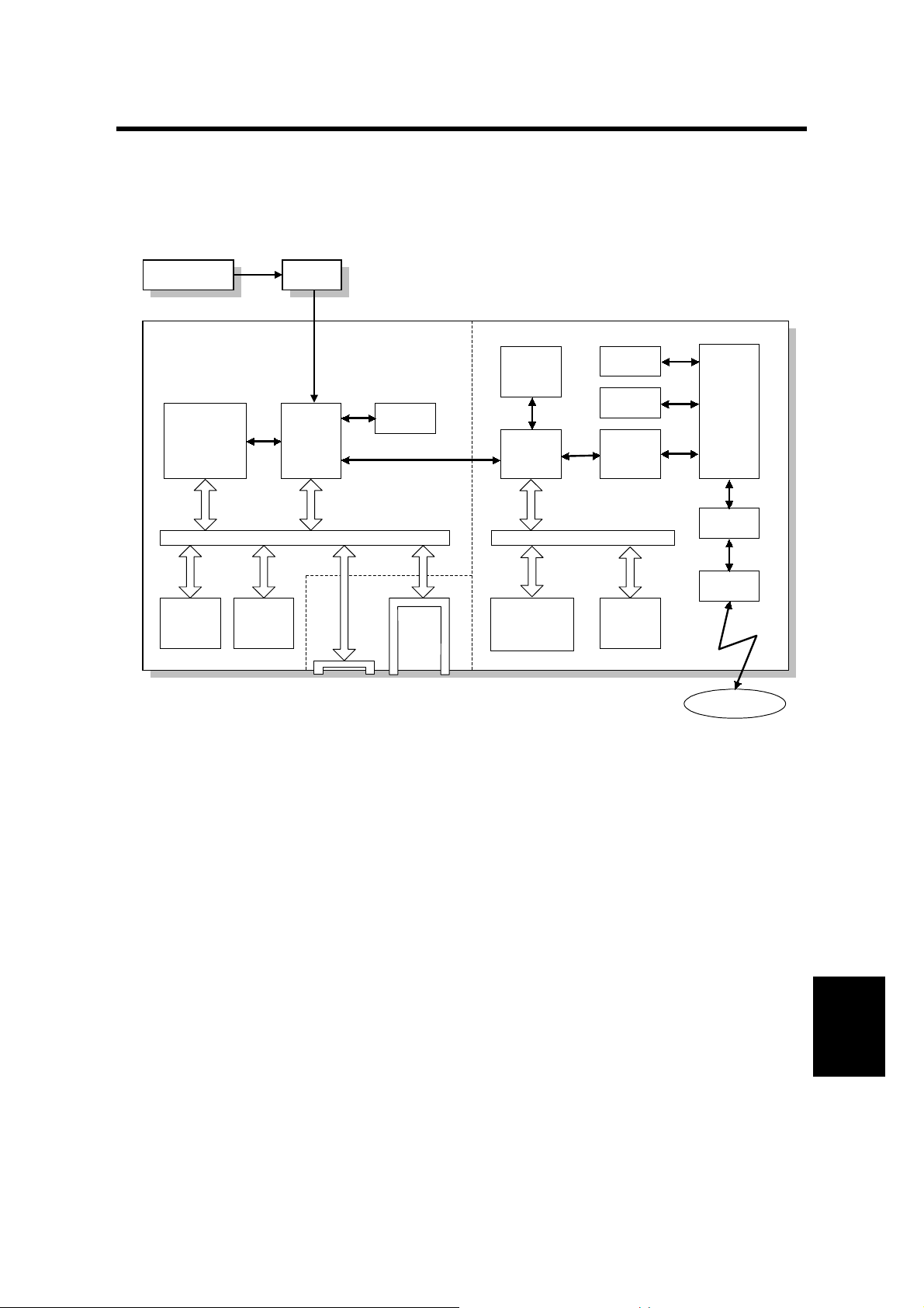
2.1 HARDWARE OVERVIEW
MBBICU
SCANNER CONTROL
BOARD
- Image Input Circuit -
CPU
UPD705101GM
(33.3 MHz)
Flash
ROM
(2 MB)
UPD65842
DRAM
(16 MB)
ASIC
DRAM
SIMM
Slot
FIFO
(256 kB)
Flash
Memory
Card
Slot
- Network Interface Circuit -
DRAM
(2 MB)
ASIC
DISCII
CPU
MC68340VP
(25.166 MHz)
SRAM
EEPROM
Bridge
AG1001V
Flash
ROM
(2 MB)
MAC
AM79C971
PHY
ICS1892
RJ45
Network
A844D500.WMF
The scanner controller contains image input and network interface circuits.
The image data from the BICU is compressed in the image input circuit, then the
data goes to the network through the network interface circuit.
Each circuit has a CPU and flash memory IC. The functions of each major
component are as follows.
2-1
KIT
SCANNER
Page 7

HARDWARE OVERVIEW 14 January, 2000
1. Image input circuit
CPU: UPD705101GM
· Sequence control for the image input circuit
· Clock/time control
· DMA control
ASIC: UPD65842
· Stores the image data from the BICU board in the main machine into the
buffer memory (DRAM)
· Address control when recalling the data from the memory
· DMA control for the network interface circuit
DRAM:
Compresses and stores the image data from the main machine (Total 16 MB.
9MB for work area, 4MB for buffer area, 3 MB for the working program)
Flash ROM:
Contains the scanner controller program and stores the UP/SP settings for
the scanner (2 MB)
2. Network interface circuit
CPU: MC58340VP
· Sequence control for the network interface circuit
· Clock/time control
· DMA control
ASIC (DISCII):
· Bus interface between the image input circuit and network interface circuit
Bridge: AG1001V
This is an ISA-PCI bridge; it corrects the timing and decodes the commands
between the ISA bus and the PCI bus.
MAC: AM79C971
This is a LAN controller; it covers the same functions as the Data Link Layer
of the OSI model.
PHY:
This device covers the same functions as the Physical Layer of the OSI
model.
Flash ROM:
Contains the program for the network interface (2 MB)
EEPROM:
Contains UP/SP settings for the network interface
2-2
Page 8

14 January, 2000 SCANNER FUNCTIONS
2.2 SCANNER FUNCTIONS
2.2.1 SELF DIAGNOSTICS
Every time the main power switch has just been turned on, the scanner board
performs the self diagnostics and the following items will be d one automatically.
· SRAM read/write test
· Flash ROM read test
· Battery test
· Initializes the network interface circuit
· Application software for scanner controller test
· Connection test between the scanner board and the main bo dy
If an error is detected, an appropriate error message or condition will be generated
(refer to the Troubleshooting section).
2.2.2 IMAGE PROCESSING IN THE SCANNER CONTROLLER
The image processing for scanner mode is done in the IPU chip on the BICU
board. However, the following processes are done in the scanner controller.
· Image compression
· Sub-scan magnification
Also, the scanner controller has a gamma table and dither matrix for scanner
mode. When the user selects the image mode using the scanner driver, the
appropriate gamma table and dither matrix are downloaded to the BICU board.
Then the IPU chip does the image processing using these tables or matrixes.
Image Compression
The image compression method for binary picture processing uses MH, MR, or
MMR, depending on scanner SP mode 002. Grayscale processing uses JPEG.
This is done by the software.
Sub-scan Magnification
Usually, the sub-scan magnification is done by changing the scanner motor speed.
However, when the amount of data being transferred is high (e.g., low resolution in
grayscale processing mode), the scanner controller deletes every other line.
2-3
KIT
SCANNER
Page 9

14 January, 2000 SCANNER FUNCTIONS
3. INSTALLATION PROCEDURE
[D]
[E]
[C]
[A] [B]
B359I502.WMF
B358I503.WMF
[H]
[I]
[F]
[G]
CAUTION
I
B359I507.WMF
B359I505.WMF
Unplug the main machine power cord before starting the following procedure.
NOTE:
If either the Printer Controller Type 450e or Fax Option Type 450e has
been installed, skip steps 1 through 8.
1. Remove the connector cover [A], rear cover [B] (4 screws), and left cover [C] (4
screws).
2. Remove the cutout [D] in the left cover.
3. Remove the HDD [E] (4 screws, 2 connectors).
4. Remove the bracket [F] (1 screw).
5. Remove the plate [G] from the expansion box (4 screws).
6. Connect the cable [H] to the expansion box [I], then install the expansion box (4
screws).
7. Reinstall the HDD.
8. Reinstall the left, rear, and connector covers.
3-1
KIT
SCANNER
Page 10

SCANNER FUNCTIONS 14 January, 2000
[C]
[A]
B359I503.WMF
[D]
[B]
B359I510.WMF
[E]
B359I601.WMF
Scanner Controller Installation
NOTE:
9. Remove plate [A] (4 screws).
10. Attach the guide plate [B] to the scanner controller board (3 screws).
11. Short TB4 [C] on the scanner board with the jumper [D].
12. If requested by the customer, install the optional SIMM memory [E] on the
If either the Scanner Option Type 450e or Fax Option Type 450e has been
installed, perform step 9. If neither have been installed, skip step 9.
scanner board.
3-2
Page 11

14 January, 2000 SCANNER FUNCTIONS
[C]
[B]
[A]
[D]
[E]
B359I509.WMF
B359I512.WMF
[I]
[H]
[F]
[J]
Copy
S
c
a
n
n
e
r
Printer/Scanner
[G]
B359I511.WMF
B359I513.WMF
13. Install the scanner controller board [A] in the third slot from the right of the
expansion box [B].
If the ISDN Option Type 450 has not been installed, skip steps 14 through 16.
14. Slide out the ISDN board [C].
15. Thread the ISDN modular cable [D] through the opening [E] in the scanner
board, as shown.
16. Insert the scanner board and ISDN board into the expansion box at the same
time.
17. Remove the cutout [F] in the plate [G] and file down any sharp edges. Reinstall
the plate.
18. Remove the bottom cap [H] of the operation panel.
NOTE:
If both Printer Controller Type 450e and Fax Option Type 450e have
not been installed, also remove the top cap of the operation panel.
19. Install the
Printer
key [I] on the operation panel and attach the
Scanner
label
[J] to the Printer key as shown.
NOTE:
If both Scanner Option Type 450e and Fax Option Type 450e have not
been installed, install the
Copy
key on the operation panel as well (see
the illustration).
3-3
KIT
SCANNER
Page 12

SCANNER FUNCTIONS 14 January, 2000
[A]
B359I514.WMF
20. Turn the machine on. If SC4003 occurs, perform the following procedure to
clear the SC condition:
NOTE:
SC4003 indicates that the battery is worn out. Even if TB4 has been
shorted with the jumper, the battery level will be low the first time the
machine is turned on after the scanner controller board is installed.
This SC condition will not occur about 30 minutes after TB4 has been
shorted.
1) Enter SP mode (
^
® a ® j ® g ® o), pressing
o
for more than
3 seconds.
2) Select 4 (Scanner SP mode).
3) Press the Next button 4 times to access SP005 (Error Log Indication).
4) Exit the SP mode.
5) Turn the machine off and on. If SC4003 still occurs, check the jumper
position.
21. Make sure that the parallel cable is not connected to the printer controller and
check the setting of the following copier SP mode (enter SP mode and select
1):
· SP5-907: Plug & Play Brand Name and Production Name Setting – select the
correct one.
22. Attach the core [A] to the STP (Shielded Twisted Pair) cable, then connect the
cable to the scanner controller.
NOTE:
The STP cord should be coiled twice inside the core as shown.
23. If the customer wishes to use the machine as a delivery fax, perform the
following.
1) Install the Fax Option Type 450e (A874) and PC Fax Expander (B368).
2) Enter the Fax SP mode and check that bit 0 of System Switch 1C is at “1”.
3) Set bit 6 of System Switch 1F to “1”.
4) Set bits 0 and 1 of User Parameter Switch 31 to “1” depending on the
delivery fax function (refer to the ScanRouter Professional Operation
Instructions Scanner & Fax Reference Type 450e for more detail).
3-4
Page 13

14 January, 2000 SERVICE PROGRAM MODE
4. SERVICE TABLE
4.1 SERVICE PROGRAM MODE
4.1.1 SERVICE PROGRAM ACCESS PROCEDURE
The service program access procedure, such as “Entering Service Program (SP)
Mode” and “Exiting SP Mode” is the same as for copier and fax, as follows.
Entering SP mode
K
® a ® j ® g ® o (hold it for more than 3 seconds.)
Exiting SP mode
Press the “Back” and “Exit” keys until the standby mode display appears.
4.1.2 SERVICE PROGRAM MODE TABLES
NOTE:
1) In the Function column, comments are in italics.
2) In the Settings column, the default value is in bold letters.
No. Function Setting
Changes the FTP port number.001 FTP Port Number
After changing this value, do the
following:
1. Run the Registry Editor.
2. Access
/HKEY_LOCAL_MACHINE/SOF
TWARE/Ricoh/NetworkScanner
3. Change the value of PortNo to
this SP mode’s value.
002 Com pr ession Type Selects the compression type for
binary picture processing.
003 Sof tware Version Displays the software version.
004 Pr ogram Number
006 Scan Dat a Reset
Displays the program’s part
number.
Displays the error logging data005 Er ror Log Display
Check this data when SC4005
occurs. Then inform it to the
service center.
Resets all scanner data (UP and
SP modes) except for the network
interface data (UP-Network-1 ~ 8)
Press “1” three times to reset.
Resets all UP and SP settings007 All Data Reset
Press “1” three times to reset.
00000 ~ 65536
1/step
3670
1: MH
2: MR
3: MMR
KIT
SCANNER
4-1
Page 14

SERVICE PROGRAM MODE 14 January, 2000
No. Function Setting
008 NIC Data Reset
Resets all network interface data
(UP-Network-1 ~ 8)
Press “1” three times to reset.
009 Density Adjustment 1 0 ~ 255
010 Density Adjustment 2
011 Density Adjustment 3 0 ~ 255
012 Density Adjustment 4 0 ~ 255
013 Density Adjustment 5
014 Density Adjustment 6 0 ~ 255
015 Density Adjustment 7
Adjusts the image density for each
image density level which can be
selected with UP mode (UP-ScanDensity)
Initializes the flash ROM.016 ROM Disk Format
1/step
40
0 ~ 255
1/step
70
1/step
100
1/step
130
0 ~ 255
1/step
160
1/step
190
0 ~ 255
1/step
220
Press “1” three times to initialize.
4-2
Page 15

14 January, 2000 DOWNLOADING NEW SOFTWARE
4.2 DOWNLOADING NEW SOFTWARE
4.2.1 SOFTWARE DOWNLOAD PROCEDURE
The software for the scanner controller contains the system software, application
software, and network interface software. The new software can be downloaded
from a flash memory card.
[B]
[A]
B359M500.WMF
1. Prepare a flash memory card that has been programmed with the latest
software.
2. Turn off the machine and disconnect the Ethernet (STP) cable from the
scanner controller.
3. Remove the cover [A], and insert the flash memory card [B] into the slot so that
the “A” side of the card faces the front of the machine.
4. Turn the machine on and press the Scanner Mode key.
5. Press the INSTALL key on the display in reply to the message. Software
download will take several minutes.
6. Make sure that the machine displays the scanner SP mode, then after new
software has been downloaded successfully, turn off the machine, remove the
card, connect the Ethernet cable, and turn the machine back on.
KIT
SCANNER
4-3
Page 16

DOWNLOADING NEW SOFTWARE 14 January, 2000
4.2.2 ERROR M E SSAGES DURING THE SOFTWARE DOWNLOAD
If downloading failed, one of the following error messages appears. At this time,
press the “CONFIRM” bottom in the display to re-try the download.
Message Action
SYS Erasing Failed ADDR:XXXXXXXX
SYS Writing Failed ADDR:XXXXXXXX
SYS Verify Failed ADDR:XXXXXXXX
APL Erasing Failed ADDR:XXXXXXXX
APL Writing Failed ADDR:XXXXXXXX
APL Verify Failed ADDR:XXXXXXXX
NIC board is not equipped
NIC Initialization failed. CODE:XXXX
NIC Download mode is disable
NIC Writing Failed ADDR:XXXXXXXX
NIC Host Service Error CODE:XXXX Re-try the download. If the download fails
Re-try the download. If the download fails
again, replace the scanner controller.
again, replace the scanner controller.
Check whether the STP cable is
disconnected. If it is connected, disconnect
the cable and re-try the downloading.
4-4
Page 17

14 January, 2000 PRECAUTION
5. REPLACEMENT AND ADJUSTMENT
5.1 PRECAUTION
CAUTION
I
Lithium Battery
The danger of explosion exists if a battery of this type is incorrectly
replaced. Replace only with the same or an equivalent type recommended
by the manufacturer. Discard used batteries in accordance with the
manufacturer’s instructions.
5.2 NOTE FOR REPLACING THE SCANNER
CONTROLLER BOARD
The scanner controller does not have a configuration report and cannot
upload/download settings to an IC card. So, before replacing the scanner controller
board, check all UP mode and SP mode settings. After replacing the board, reinput these settings.
5-1
KIT
SCANNER
Page 18

14 January, 2000 SERVICE CALL CO NDI TION
6. TROUBLESHOOTING
6.1 SERVICE CALL CONDITION
The scanner controller board automatically performs the self diagnostics whenever
the main power switch is turned on. If an error is detected, it displays an error
message on the LCD. Turn the main switch off and on to reset the SC condition.
6.1.1 SC CODE DESCRI PTIONS
SC code Error Items Conditions Action
Replace or re-install the
SIMM
Replace the scanner
controller board
download the software. If
the download fails, replace
the scanner controller.
Replace the scanner
controller board
Change the jumper position
Replace the scanner
controller board
and on, check the error log
data (SP005), then inform it
to the service center.
SC4001
SC4002
SC4003
SC4004
SC4005
DRAM Error
Flash ROM
Error
Battery Error
NIC Error NIC circuit defective
Application
Error
SIMM defective
·
A SIMM type other than
·
16MB or 32MB SIMM is
installed
Standard SRAM
·
defective
The machine cannot scan Defective firmware; try to
The battery has run out
·
The jumper TB4 is at the
·
off position
Logical error Turn the main switch off
6-1
KIT
SCANNER
Page 19

LEDS 14 January, 2000
6.2 LEDS
B359T500.WMF
LED No. Color Status Condition
LED1 Yellow
LED2 Green
LED3 Green
LED5 Red
Lit The network interface circuit is working properly.
Off The network interface circuit does not work.
Lit
Off
Lit 100 Base-TX
Off 10 Base-T
Lit + 5V is supplied
Off + 5V is not supplied
Blinking
The scanner controller board is connected to the
network properly.
The scanner controller board is not connected to the
network.
Communication error between the scanner controller
board and BICU.
6-2
 Loading...