

Page 1

DUPLEX
(Machine Code: A896/B414)
Page 2

10 August, 2001 SPECIFICATIONS
1. OVERALL MACHINE INFORMATION
1.1 SPECIFICATIONS
Paper Size:
Paper Weight: 64 g/m2 ~ 105 g/m2, 20 lb ~ 28 lb
Tray Capacity: 1 sheet
Power Consumption: 40 W
Power Source: DC 24 V, 5 V
Dimensions (W x D x H): 90 x 495 x 452 mm
Weight: 6 kg
Standard sizes
A5 lengthwise to A3
HLT to DLT
Non-standard sizes
Width: 140 to 297 mm
Length: 182 to 432 mm
B414-1
Options
Page 3
MECHANICAL COMPONENT LAYOUT 10 August, 2001
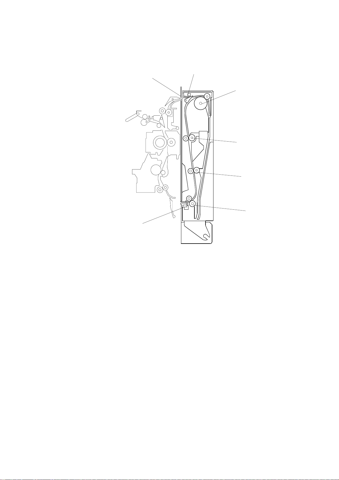
1.2 MECHANICAL COMPONENT LAYOUT
1
2
3
4
5
6
7
1. Inverter Gate
2. Entrance Sensor
3. Inverter Roller
4. Upper Transport Roller
B414V500.WMF
5. Middle Transport Roller
6. Lower Transport Roller
7. Exit Sensor
B414-2
Page 4
10 August, 2001 ELECTRICAL COMPONENT LAYOUT
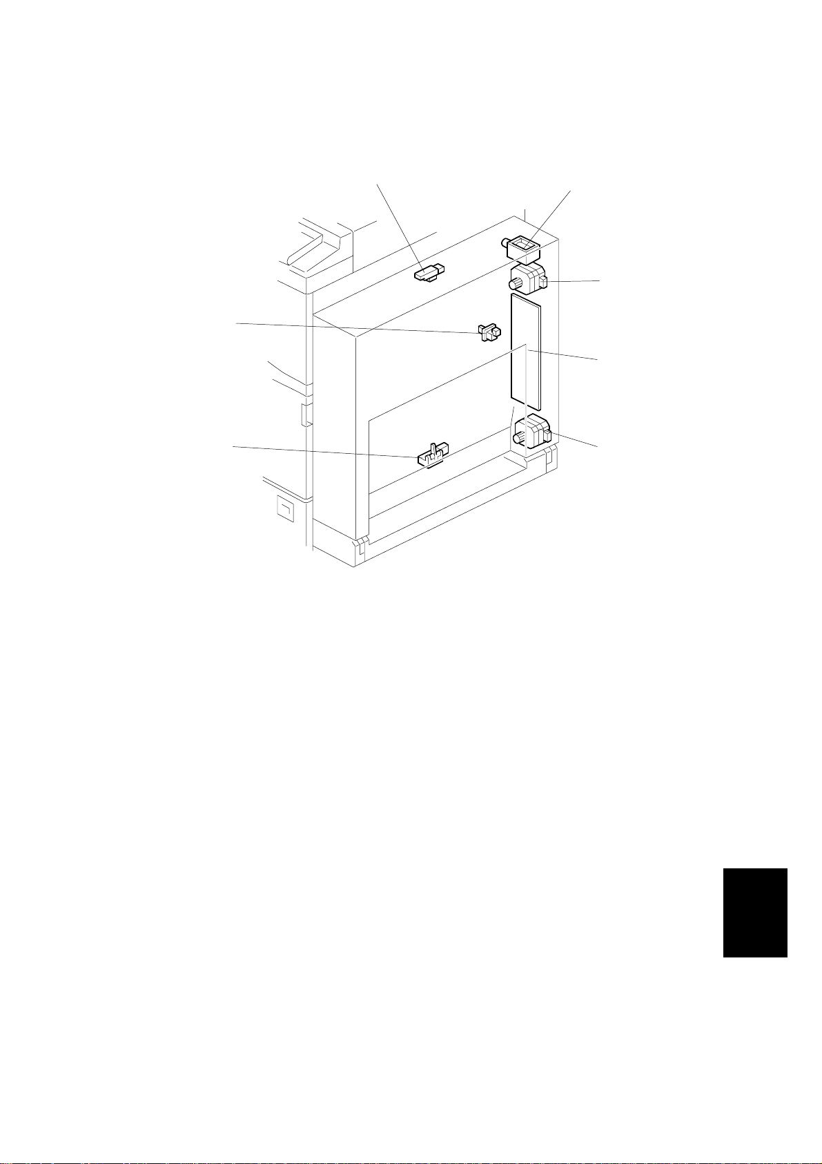
1.3 ELECTRICAL COMPONENT LAYOUT
1
2
3
7
4
6
5
1. Entrance Sensor
2. Inverter Gate Solenoid
3. Inverter Motor
4. Main Board
B414V501.WMF
5. Transport Motor
6. Exit Sensor
7. Duplex Unit Open Switch
Options
B414-3
Page 5

ELECTRICAL COMPONENT DESCRIPTION 10 August, 2001
1.4 ELECTRICAL COMPONENT DESCRIPTION
Symbol Name Function Index No.
Motors
M1 Inverter Drives the inverter roller. 3
M2 Transport Drives the upper and lower transport rollers. 5
Sensors
Entrance Detects the trailing edge of the copy paper to
S1
S2 Exit Checks for misfeeds. 6
Switches
SW1
Solenoids
SOL1 Inverter Gate Controls the inverter gate. 2
Duplex Unit
Open
turn on the inverter gate solenoid and turn on
the inverter motor in reverse. Checks for
misfeeds.
Detects whether the duplex unit is opened or
not.
1
7
PCBs
PCB1
Main Controls the duplex unit and communicates
with the copier.
4
B414-4
Page 6

10 August, 2001 DRIVE LAYOUT
1.5 DRIVE LAYOUT
1
2
3
4
1. Inverter Roller
2. Inverter Motor
3. Upper Transport Roller
5
6
B414V502.WMF
4. Transport Motor
5. Lower Transport Roller
6. Middle Transport Roller
Options
B414-5
Page 7

BASIC OPERATION 10 August, 2001
2. DETAILED DESCRIPTIONS
2.1 BASIC OPERATION
To increase the productivity of the duplex unit, copies are printed as follows.
Longer than A4 sideways/LT sideways
The duplex unit can store only one sheet of copy paper.
Example: 8 pages. The number [A] in the illustration shows the order of pages. The
number [B] in the illustration shows the order of sheets of copy paper (if
shaded, this indicates the second side).
⇒⇒4⇒⇒6⇒⇒8⇒
1 1 42 2 3 3 4
5312
7
B414D519.WMF
B414-6
B414D518.WMF
Page 8

10 August, 2001 BASIC OPERATION
Up to A4 sideways/LT sideways
The duplex unit can store two sheets of copy paper
Example: 8 pages. The number [A] in the illustration shows the order of pages. The
number [B] in the illustration shows the order of sheets of copy paper (if
shaded, this indicates the second side).
⇒⇒⇒⇒6⇒⇒8⇒
4 1 532
1 423 3412
B414D520.WMF
7
B414-7
Options
B414D517.WMF
Page 9

FEED IN AND EXIT MECHANISM 10 August, 2001
2.2 FEED IN AND EXIT MECHANISM
[A]
[B]
[G]
[D]
[C]
[E]
[F]
B414D504.WMF
B414D505.WMF
When paper is fed into duplex unit:
As soon as the paper arrives from the interchange unit, it is sent to the inverter
section [C] (the inverter gate solenoid [A] remains off during this process).
The inverter section can hold a sheet of paper up to A3 size. Because of this, the
cover guide used in the previous model has become obsolete and has been
eliminated from the design.
Inversion and Exit:
Shortly after the trailing edge of the paper passes the entrance sensor [G], the
inverter gate solenoid [A] switches on and the inverter gate [B] switches over to
direct the paper to the exit path [E]. The inverter roller [D] then changes its rotation
direction and the paper goes to the exit transport area [F]. The paper is then sent
to the registration rollers in the main copier via the transport rollers.
B414-8
Page 10

10 August, 2001 COVER REMOVAL
3. REPLACEMENT AND ADJUSTMENT
3.1 COVER REMOVAL
[A]
1. Remove the duplex unit cover [A] (4 screws).
B414R501.WMF
Options
B414-9
Page 11

ENTRANCE SENSOR REPLACEMENT 10 August, 2001
3.2 ENTRANCE SENSOR REPLACEMENT
[A]
B414R502.WMF
1. Remove the duplex unit cover. (Refer to section 3.1.)
2. Remove the sensor holder [A] (1 screw).
3. Replace the entrance sensor [B] (1 connector, 1 screw).
[B]
B414-10
Page 12

10 August, 2001 EXIT SENSOR REPLACEMENT
3.3 EXIT SENSOR REPLACEMENT
[B]
[C]
[A]
1. Open the duplex unit [A].
2. Remove the sensor bracket [B] (1 screw).
3. Replace the exit sensor [C] (1 connector).
B414R503.WMF
Options
B414-11
 Loading...