

Page 1

DUPLEX UNIT
(Machine Code: G552)
Page 2
10 October, 2000 EXTERIOR COVERS
1. REPLACEMENT AND ADJUSTMENT
!
CAUTION
Turn off the main power switch and unplug the machine before attempting
any of the procedures in this section.
NOTE: This manual uses several symbols. The meanings of those symbols are as
follows:
☛: See or Refer to
!: screw
": connector
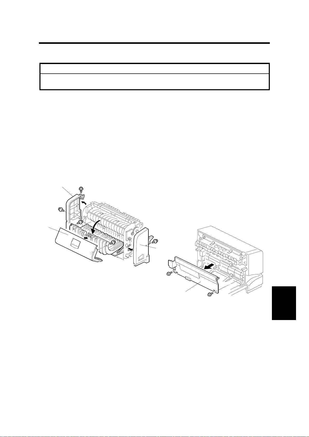
1.1 EXTERIOR COVERS
[B]
[A]
[C]
G552R101.WMF
• Remove the duplex unit from the main unit.
• Open the upper cover [A].
[D]
G552R102.WMF
Peripherals
[A]: Upper cover (! x2)
[B]: Right cover (! x2)
[C]: Left cover (! x1)
[D]: Front cover (! x2)
1-1
Page 3
DUPLEX BOARD AND SENSORS 10 October, 2000
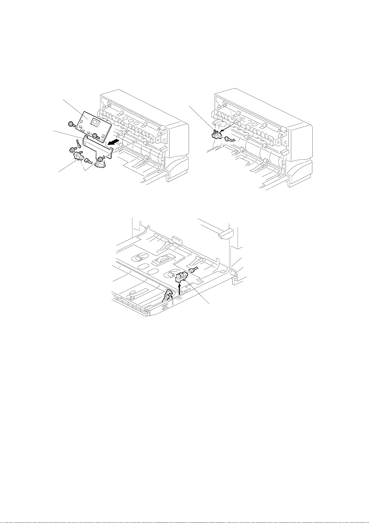
1.2 DUPLEX BOARD AND SENSORS
[B]
[D]
[A]
[C]
G552R103.WMF
• Front cover (☛ Exterior Covers)
[A]: Duplex board bracket (! x2)
[B]: Duplex board (! x2, all connectors)
[C]: Inverter sensor (" x1)
[D]: Entrance sensor (" x1)
[E]: Exit sensor (" x1)
G552R104.WMF
[E]
G552R105.WMF
1-2
Page 4

10 October, 2000 OVERALL MACHINE INFORMATION
2. DETAILED DESCRIPTION
2.1 OVERALL MACHINE INFORMATION
2.1.1 MECHANICAL COMPONENT LAYOUT
2
1
4
3
5
1. Junction gate
2. Entrance sensor
3. Inverter rollers
4. Transport rollers
5. Transport sensor
6. Exit sensor
6
G552V101.WMF
Peripherals
2-1
Page 5

OVERALL MACHINE INFORMATION 10 October, 2000
2.1.2 DRIVE LAYOUT
3
2
1
4
G552V103.WMF
1. Inverter rollers
2. Inverter motor
3. Transport motor
4. Transport rollers
2.1.3 ELECTRICAL COMPONENT LAYOUT
4
3
1. Entrance sensor
G552V105.WMF
1
5
2. Junction gate solenoid
3. Inverter motor
4. Duplex board
5. Transport motor
6. Inverter sensor
7. Exit sensor
6
2
7
G552V104.WMF
2-2
Page 6

10 October, 2000 DETAILED SECTION DESCRIPTIONS
2.2 DETAILED SECTION DESCRIPTIONS
2.2.1 BASIC OPERATION
Longer than A4 LEF/LT LEF
• The duplex unit can store only one sheet of paper.
Example: 8 pages. The cent er number in the illustration shows the order of pages.
The number with the circle in the illustration shows the order of sheets of
print paper (if highlighted, this indicates the second side).
1 2 3 4 5 6 7 8
➀➁$%➃'➂
)
G552I500.WMF
2-3
Peripherals
G552D106.WMF
Page 7

DETAILED SECTION DESCRIPTIONS 10 October, 2000
Length up to A4 LEF/LT LEF
• The duplex unit can store three sheets of paper
Example: 8 pages. The cent er number in the illustration shows the order of pages.
The number with the circle in the illustration shows the order of sheets of
print paper (if highlighted, this indicates the second side).
1 3 7 6 8
➀➁ ➃
5
➂
)
2
$
4
%*
G552I501.WMF
2-4
G552D107.WMF
Page 8

10 October, 2000 DETAILED SECTION DESCRIPTIONS
2.2.2 FEED IN AND EXIT MECHANISM
[B]
[C]
[A]
[E]
[D]
[F]
[G]
Feeding paper into the duplex unit:
• The junction gate solenoid [A] turns on to open the junction gate [B].
• The paper fed from the main frame is sent to the inverter section [C].
G552V102.WMF
Inversion and exit:
• After the trailing edge of the paper passes the inverter sensor [D], the inverter
roller [E] changes its rotation direction and the paper goes to the transport area
[F].
• The transport rollers [G] send the paper to the registration rollers in the main
frame.
2-5
Peripherals
 Loading...