


DUPLEX UNIT
17 January, 2001 COVERS AND PAPER GUIDES
1. REPLACEMENT AND ADJUSTMENT
1.1 COVERS AND PAPER GUIDES
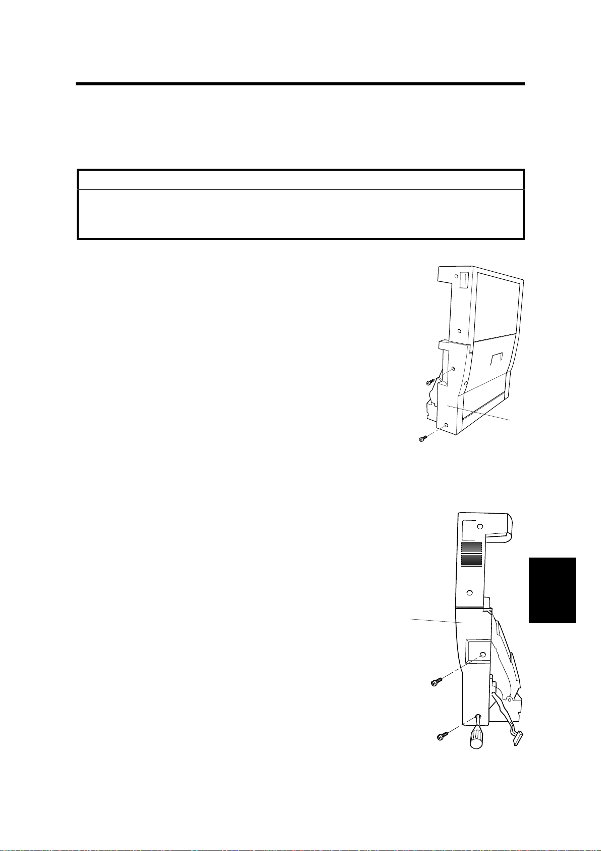
1.1.1 RIGHT SIDE COVER LOW
!
CAUTION
It is normally necessary to remove the duplex unit from the printer when
servicing the duplex unit. The duplex unit is heavy. Take care not to injure
yourself by dropping the duplex unit when removing and installing it.
1. Right Side Cover Low [A] (! x 2).
1.1.2 LEFT SIDE COVER LOW
1. Left Side Cover Low [A] (! x 2).
[A]
[A]
G657R520.WMF
Peripherals
G657D-1
G657R521.WMF

COVERS AND PAPER GUIDES 17 January, 2001
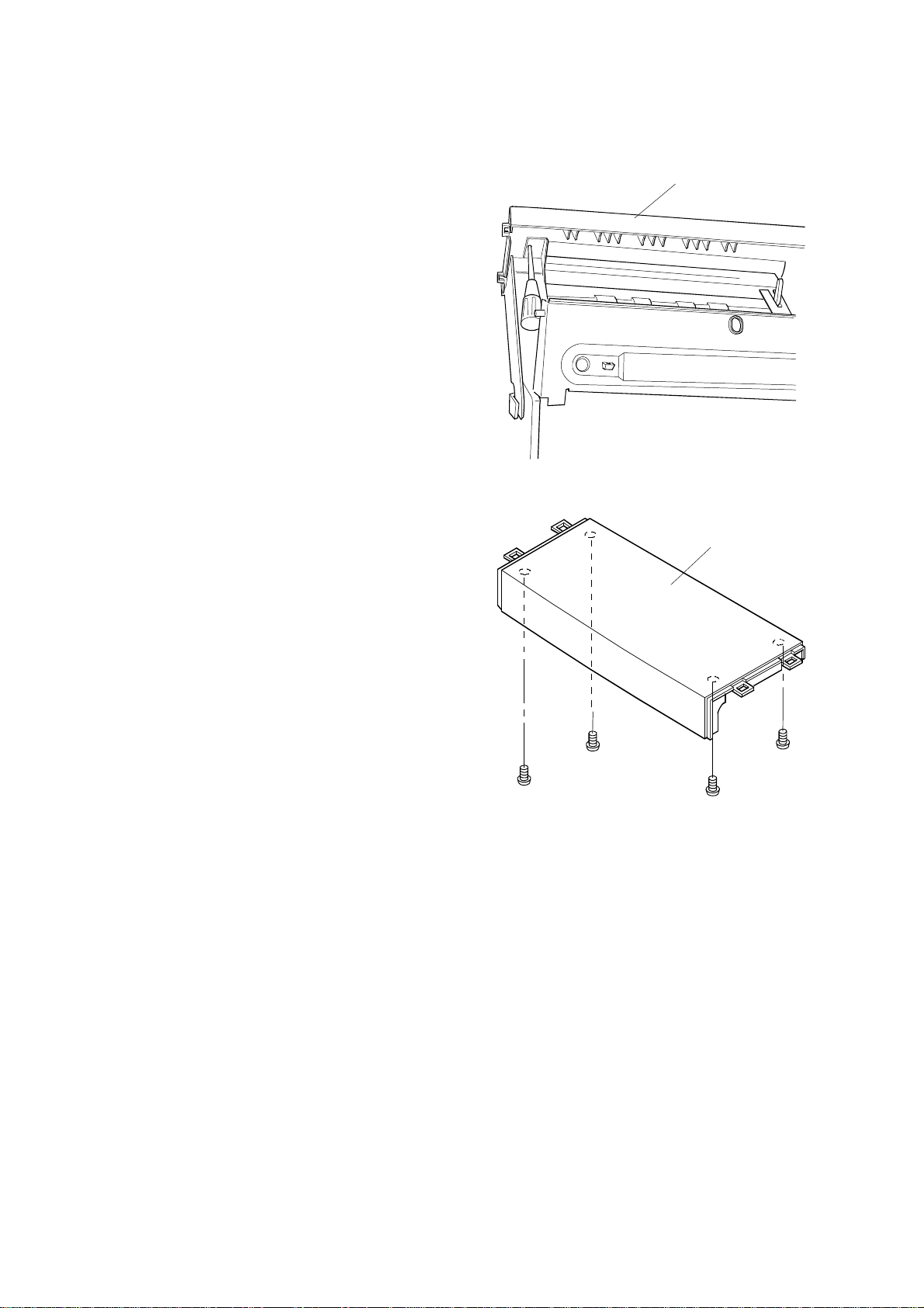
1.1.3 RIGHT COVER TOP
1. Right Cover Top [A] (! x 2).
[A]
1.1.4 LEFT COVER TOP
1. Left Side Cover Low (☛ 1.1.2).
2. Left Cover Top [B] (2 hooks, 1 clamp).
G657R524.WMF
[B]
G657D-2
G657R525.WMF

17 January, 2001 COVERS AND PAPER GUIDES
1.1.5 COVER TOP ASSY 1 (WITH 4 GUIDE ROLLERS)
1. Right Side Cover Low (☛ 1.1.1).
2. Right Cover Top (☛ 1.1.3)
3. Duct [A] (! x 2).
4. Open the Duplex Top Cover Unit [B].
5. Cover Top Ass’y 1 [C] (! x 4, 3 hooks), from the upper
unit [D].
[D]
[C]
[B]
G657R501.WMF
[C]
G657R526.WMF
[A]
G657R527.WMF
Peripherals
G657D-3
COVERS AND PAPER GUIDES 17 January, 2001
1.1.6 COVER TOP ASSY 2 (WITH 4 GUIDE ROLLERS)
[A]
1. Right Side Cover Low, Left Side Cover
Lows, Right Cover Top, Left Cover Top
(☛ 1.1.1 through 1.1.4)
2. Fan Motor (! x 4).
3. Cover Top Ass’y 2 [A] (! x 4).
G657R502.WMF
[A]
G657R528.WMF
G657D-4
17 January, 2001 COVERS AND PAPER GUIDES
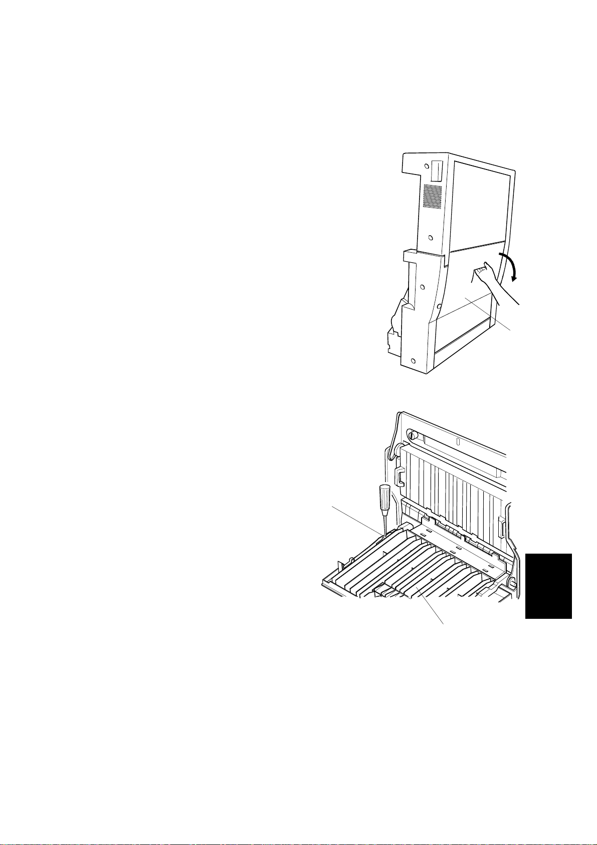
1.1.7 COVER LOW ASSY (INCLUDING 4 GUIDE ROLLERS,
HANDLE, AND LOCK LEVER)
1. Open the Cover Low [A].
2. Cover Low Ass’y [A] (! x 4), from the hinge metal
fixture [B].
[A]
[B]
[A]
G657R516.WMF
G657R504.WMF
Peripherals
G657D-5
COVERS AND PAPER GUIDES 17 January, 2001
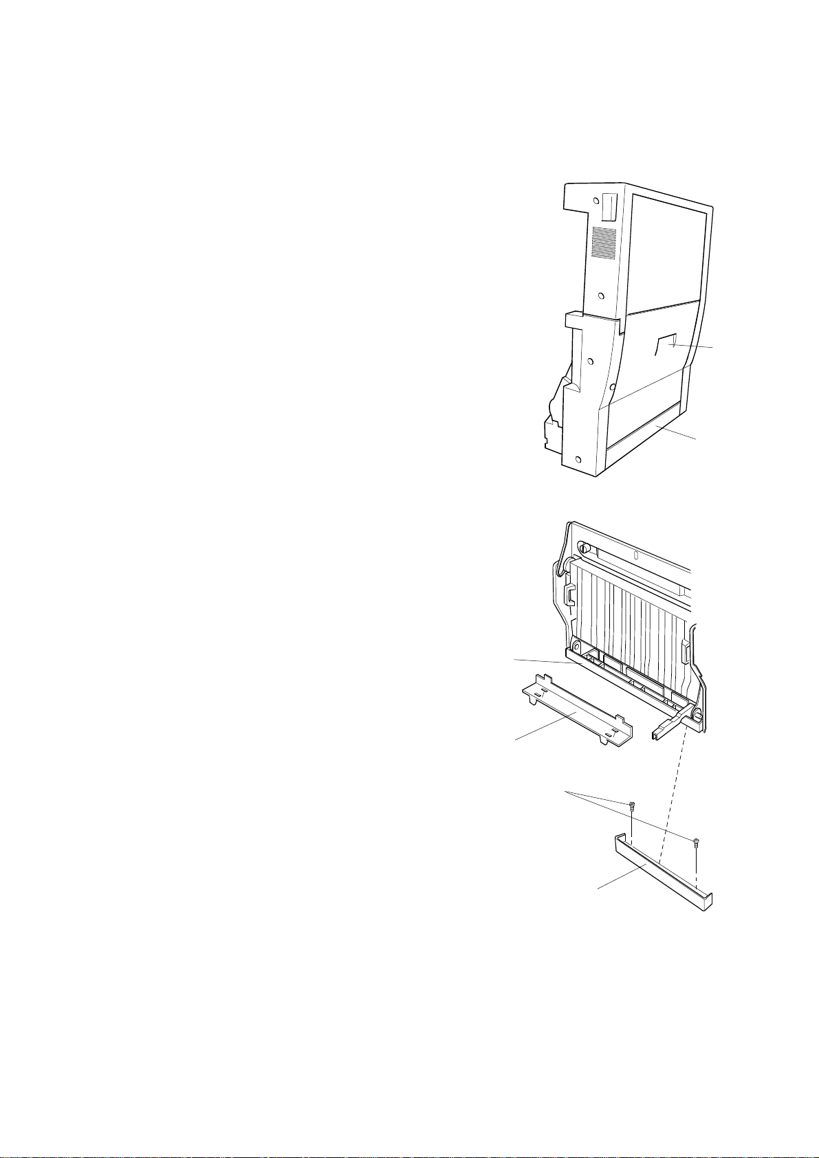
1.1.8 BOTTOM COVER ASS’Y
1. Separate the D-Lower unit from the D-Top unit (☛
1.2)
2. Cover Low Ass’y [A] (☛ 1.1.7)
3. Harness cover [B].
4. Screws [C] (M4 x 6, 2 pcs), from the bottom cover.
5. Harness inside the bottom cover.
6. Paper guide RVS unit (☛ 1.1.9).
7. Bottom cover [D], from the base.
[A]
[D]
G657R501.WMF
[D]
[B]
G657D-6
[C]
[D]
G657R503.WMF
17 January, 2001 COVERS AND PAPER GUIDES
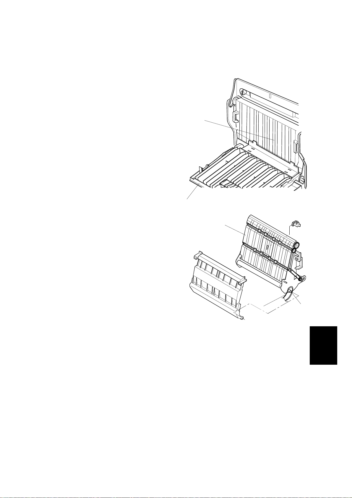
1.1.9 PAPER GUIDE RVS UNIT
1. Right Cover Low and Left Cover Low.
(☛ 1.1.1 and 1.1.2)
2. Paper Guide RVS IN. (☛ 1.1.10)
3. Screws (M3 x 5, 4 pcs.) from the
support sh aft at both sides (left & right).
After this, the Cover Low Assy [A].
comes off (☛ 1.1.7)
4. Support shaft, from the frame.
5. Retaining band [B], from the Paper
Guide RVS Unit [C].
6. Paper guide bottom (☛ 1.1.11)
7. Harness connected to connector CN2
on the Relay board.
8. Paper guide RVS Unit [C], from the
frame.
NOTE: When putting back the Paper
Guide RVS unit and Paper Gu ide
RVS IN, pass the retaining band
[B] through the shaft [D].
[C]
G657R506.WMF
[A]
[C]
G657D-7
[B]
[D]
G657R530.WMF
Peripherals

COVERS AND PAPER GUIDES 17 January, 2001
1.1.10 PAPER GUIDE RVS IN
1. Open the Cover Low [A].
2. Open the Paper Guide RVS Unit [B].
3. Flex the hinge arms [C] of Paper Guide
RVS IN slightly away from the shaft.
4. Paper Guide RVS IN [D].
NOTE: When putting back the Paper
Guide RVS IN [D], pass the
retaining band [E] through the
shaft [F].
[B]
[A]
G657R505.WMF
[D]
[F]
G657D-8
[C]
G657R530.WMF
[E]

17 January, 2001 COVERS AND PAPER GUIDES
1.1.11 PAPER GUIDE BOTTOM
1. Open the Cover Low.
2. Open the Paper Guide RVS Unit [A].
3. Paper Guide Bottom [B] (! x 1, 4
hooks, connector x 1).
[B]
[A]
G657R531.WMF
G657D-9
Peripherals

PAPER TOP ASSY 17 January, 2001
1.2 PAPER TOP ASSY
1.2.1 SEPARATION OF D TOP UNIT AND D LOWER UNIT
1. Right Cover Low, Left Cover Low. (☛ 1.1.1
and 1.1.2)
2. Disconnect the solenoid, and remove the cable
from the clamp.
3. Disconnect the fan, and remove the cable from
the clamp.
4. Remove the screws [A] from the support pins
at both sides (M4 x 8, 1 each at left and right).
5. Open the D-Top Unit [B] and separate the D
Top Unit and D Lower Unit [C].
[B]
[C]
G657R512.WMF
[B]
[C]
G657R511.WMF
[A]
1.2.2 PAPER GUIDE TOP ASSY
G657R529.WMF
1. Right Cover Top and Left Cover Top from the D-Top Unit. (☛ 1.1.3 and 1.1.4)
2. Cover Top 1 from the D-top unit. (☛ 1.1.5)
3. Cover Top 2 from the D-top unit. (☛ 1.1.6)
G657D-10

17 January, 2001 PCB
1.3 PCB
1.3.1 DUPLEX UNIT CONTROLLER BOARD
1. Paper Guide Bottom [A]. (☛ 1.1.11)
2. Duplex unit controller board [B] (! x 4, 1
connector).
[A]
G657R513.WMF
G657R532.WMF
[B]
Peripherals
G657D-11

PCB 17 January, 2001
1.3.2 RELAY BOARD
1. Paper Guide Bottom [A]. (☛ 1.1.11)
2. Disconnect all the connectors connected to the
Relay board [B].
3. Relay board [B] (! x 3).
G657R513.WMF
[A]
[B]
G657R532.WMF
G657D-12

17 January, 2001 MOTORS
1.4 MOTORS
1.4.1 MOTOR (1)
1. Paper Guide Bottom (☛ 1.1.11) and the Right
Side Cover Low (☛ 1.1.1)
2. Disconnect the motor cable from the Relay board
CN5.
3. Remove the cable from the clamp.
4. Remove the protective cover (3 hooks).
5. Motor (1) [A ] (! x 2), from the frame.
NOTE: The motor cable must not contact the gear.
G657R522.WMF
[A]
Peripherals
G657D-13

MOTORS 17 January, 2001
1.4.2 MOTOR (2)
1. Paper Guide Bottom [A] (☛ 1.1.11) and
Left Side Cover Low (☛ 1.1.2).
2. Disconnect the motor cable from the Relay
board CN7.
3. Harness Cover, and remove the cable
from the clamp.
4. Protective cover [B] (3 hooks).
5. Belt, from the motor shaft [C].
6. Motor (2) [D] (! x 2) from the frame.
[D]
[D]
[C]
G657R514.WMF
[A]
G657R517.WMF
G657D-14

17 January, 2001 MOTORS
1.4.3 FAN MOTOR
1. Left Side Cover Low. (☛1.1.2)
2. Left Cover Top. (☛ 1.1.4)
3. Disconnect the fan cable [A].
4. Remove the harness from the clamp.
5. Fan motor [B] (M4 x 30, ! x 20) from
the frame.
[A]
[B]
G657R523.WMF
G657D-15
Peripherals

SOLENOID ASSEMBLIES 17 January, 2001
1.5 SOLENOID ASSEMBLIES
1.5.1 UPPER SOLENOID ASS’Y
1. Right Side Cover Low (☛
1.1.1).
2. Right Cover Top (☛ 1.1.3).
3. Ventilation Duct [A] (! x 2).
4. Disconnect the solenoid cable.
5. Remove the cable [B] from the
clamp.
6. Upper Solenoid Ass’y [C] (! x
2).
1.5.2 LOWER SOLENOID ASS’Y
1. Paper Guide Bottom. (☛
1.1.11)
[A]
[C]
[B]
G657R515.WMF
2. Harness Cover.
3. Disconnect the Solenoid (L)
cable from the Relay board [A]
at CN3
4. Remove the cable from the
clamp.
5. Lower Solenoid Ass’y [B] (! x
1).
NOTE: When attaching the Lower
Solenoid, put the actuator
in the lever hole in the
Lower Junction Gate.
[A]
[B]
G657R518.WMF
G657D-16

17 January, 2001 SENSORS AND SWITCHES
1.6 SENSORS AND SWITCHES
1.6.1 INTERLOCK SWITCHES (D-SW1, D-SW2)
1. Right Side Cover Low. (☛ 1.1.1)
2. Interlock switches [A, B] (! x 1, connector x 1)
• A: Interlock Switch to detect when the Top
Unit is open.
• B: Interlock Switch to detect when the Cover
Low is open.
NOTE: After replacing an interlock switch, confirm
that it operates normally by opening and
closing the Right Cover Low.
[A]
1.6.2 INTERLOCK SWITCH (D-SW3, D-SW4)
1. Left Side Cover Low. (☛ 1.1.2)
2. Interlock switches [A, B] (! x 1, connector x
1).
• A: Interlock Switch to detect when the Top
Unit is open.
• B: Interlock Switch to detect when the Side
Cover Low (B) is open.
NOTE: After replacing an interlock switch,
confirm that it operates normally by
opening and closing the Right Cover Low.
[A]
[B]
[B]
G657R507.WMF
Peripherals
G657R510.WMF
G657D-17

SENSORS AND SWITCHES 17 January, 2001
1.6.3 DUPLEX PAPER SENSOR (PT5)
1. Open the Cover Low.
2. Open the Paper Guide RVS IN [A].
3. Sensor Cover [B] (! x 1).
4. PT5 [C] (connector x 1, feeler x 1),
from the Paper Guide RVS Unit.
1.6.4 PAPER SENSOR LOW (PT4)
[C]
[B]
[A]
G657R519.WMF
1. Paper Guide Bottom [A]. (☛ 1.1.11)
2. PT4 [B], from the Paper Guide Bottom
Assembly [C] (2 hooks, connector x 1).
[A]
G657R509.WMF
[C]
G657D-18
G657R508.WMF
[B]

17 January, 2001 INTERNAL STRUCTURE
2. DETAILED SECTION DESCRIPTIONS
2.1 INTERNAL STRUCTURE
[4]
[2]
[2]
[2]
[7]
[2]
[3]
1-2.WMF
[6]
No. Name of Part Function
1 LFU Unit Lower Feed Unit.
2 Transport Rollers Transportation of paper.
3 D-Registration Roller Registration of duplex print paper.
4 Upper Junction Gate Switching of paper to the duplex unit.
5 Lower Junction Gate Switching of paper fro m the duplex unit.
6 D-Sensor (PT4) Paper Sensor (PT4).
7 D-Sensor (PT5) Paper Sensor (PT5).
[5] [A]
Duplex Print Paper Feeding Guide.
[1]
Peripherals
G657D-19

PAPER FEED PATH FOR DUPLEX PRINTING 17 January, 2001
2.2 PAPER FEED PATH FOR DUPLEX PRINTING
2.2.1 FEED PATH FOR PRINTING THE REAR SIDE (B FACE)
1. After the image for the B face is formed on the transfer drum, paper is fed from
the paper cassette, aligned by the registration roller [A], and fed to the transfer
unit for transferring the image onto the B face.
2. For duplex printing, the upper junction gate [4] (in the paper exit unit) guides
paper fed from the fusing unit into the upper part of the duplex unit.
3. Then, this paper is fed into the lower unit (the paper guide RVS unit) by the
transport rollers [2] and the paper guide (UF).
4. The paper is detected by the paper sensor (PT5) [7] and aligned by the Dregistration roller [3]. Then it is guided by the lower junction gate [5] into the
paper guide RVS unit.
2.2.2 FEED PATH FOR PRINTING THE FRONT SIDE (A FACE)
1. When the image for the A face has been formed on the transfer drum, the
printed paper is fed backwards out of the RVS unit.
2. The lower junction gate [5] is switched, and the paper goes through the bottom
guide and is detected by the paper sensor (PT4) [6]. Then, it goes through the
paper guide of the lower feeder unit (LFU) [1], and back up to the paper feed
path (registration roller in the main body).
3. After being aligned by the registration roller [A], the paper is fed to the transfer
unit and the image is transferred to the A face.
4. The paper goes through the fusing unit, and is fed out to the top cover by
switching the upper junction gate [4] in the paper exit unit.
G657D-20

17 January, 2001 DUPLEX PRINT MODES
2.3 DUPLEX PRINT MODES
There are three duplex print modes that you can select either at the operation
panel or with the driver.
2.3.1 DUP-1 MODE
This is standard speed mode.
It is available for single, 2, 3, or 4 colour printing.
Only one sheet of paper is fed at a time.
Operation sequence:
➀ B → ➀ A → ➁ B → ➁ A
First, the print is made on the rear side (B face) of the paper, and the paper is fed
into the duplex unit. Then, the paper is fed from the duplex unit to the paper feed
path in the main body of the printer, then the print is made on the front side (A
face) of the paper.
On the diagrams:
1B – Sheet 1 with only the B side
printed
1AB – Sheet 1 with both A and B
sides printed
15A.WMF
15D.WMF
G657D-21
Peripherals

DUPLEX PRINT MODES 17 January, 2001
2.3.2 DUP-2 MODE
This is medium speed mode.
It is available for single, 2, 3, or full color printing.
Two sheets of paper are fed at a time.
Operation sequence:
➀ B → ➁ B → ➀ A → ➀ A
First, the rear sides (B faces) of two sheets are printed, and these sheets are fed to
the duplex unit. Then, they are fed back into the paper feed path in the print er main
body and the front sides (A faces) of the two sheets are printed.
15B.WMF
15E.WMF
G657D-22

17 January, 2001 DUPLEX PRINT MODES
2.3.3 DUP-3 MODE
This is high speed mode.
It is available for single color printing only.
Three sheets of paper are in the paper feed path at one time.
Operation sequence: ➀ B → ➁ B → ➂ B → ➀ A → ➃ B → ➁ A → ➄ B → ➂ A
➅
→
B →
1. First, the rear sides (B faces) of the first three sheets are printed.
2. Then, the A face of the first sheet is printed.
3. The second and third sheets are still on their way back towards the paper feed
path inside the printer, so the machine next prints the B face of the fourth
sheet.
4. Then, the A face of the second sheet is printed.
5. Then, the B face of the fifth sheet is printed.
6. Then, the A face of the third sheet is printed.
7. Then, the B face of the fifth sheet is printed, and so on.
15C.WMF
15F.WMF
Peripherals
G657D-23
 Loading...