

Page 1

DUPLEX UNIT (G694)
Page 2

1 August 1996 SPECIFICATIONS
1. SPECIFICATIONS
Copy Paper Size : Width
Max. 297 mm, Min. 182 mm
Length
Max. 432 mm, Min. 148 mm
Paper Weight : 60 g to 90 g
Capacity: 1 sheet
Power Source : 24 Vdc from the copier
Power Consumption : 25 W
Dimensions (W x D x H) : Duplex Tray - 530 x 565 x 255 mm
Inverter Unit - 75 x 428 x 101 mm
Weight : Duplex Tray - 4.1 kg
Inverter Unit - 1 kg
G694-1
Page 3
COMPONENT LAYOUT 1 August 1996
2. COMPONENT LAYOUT
2.1 MECHANICAL COMPONENT LAYOUT
1
7
6
1. Duplex Junction Gate
2. Inverter Unit Transport Roller
3. Duplex Feed Roller
2
45
5. Left Transport Roller
6. Duplex Tray
7. Inverter Unit
3
G694O006.wm f
4. Central Transport Roller
G694-2
Page 4

1 August 1996 COMPONENT LAYOUT
2.2 ELECTRICAL COMPONENT LAYOUT
1
5
4
G694O002.wmf
2
3
6
1. Duplex Control Board
2. Duplex Turn Sensor
3. Duplex Exit Sensor
4. Duplex Feed Motor
7
G694O003.wmf
5. Duplex Transport Motor
6. Duplex Junction Gate Solenoid
7. Duplex Entrance Sensor
G694-3
Page 5

COMPONENT LAYOUT 1 August 1996
2.3 ELECTRICAL COMPONENT DESCRIPTION
Symbol
Motors
M1 Duplex Transport Drives the left and central tran sport rollers. 5
M2 Duplex Feed Drives the duplex feed roller. 4
Sensors
S1 Duplex Entrance
S2 Duplex Turn
S3 Duplex Exit
Solenoid
SOL1
PCBs
PCB1 Duplex Control Controls the overal l duplex tray oper at ion. 1
Duplex Juncti on Gate
Control
Name Function
Detects misfeeds and controls the transport
motor speed.
Detects misfeeds, controls the paper stop
position, and cont rols the duplex fee d roller
timing.
Detects misfe eds and controls the duplex
feed roller off timing.
Controls the dupl ex junction gate. 6
Index
No.
7
2
3
G694-4
Page 6
1 August 1996 DRIVE LAYOUT
3. DRIVE LAYOUT
1
5
2
3
1. Left Transport Roller
4
G694o004.wmf
6
G694O005.wmf
4. Duplex Feed Motor
2. Central Transport Roller
3. Duplex Feed Roller
5. Transport Motor
6. Inverter Unit Transport Roller
G694-5
Page 7

BASIC OPERATION 1 August 1996
4. BASIC OPERATION
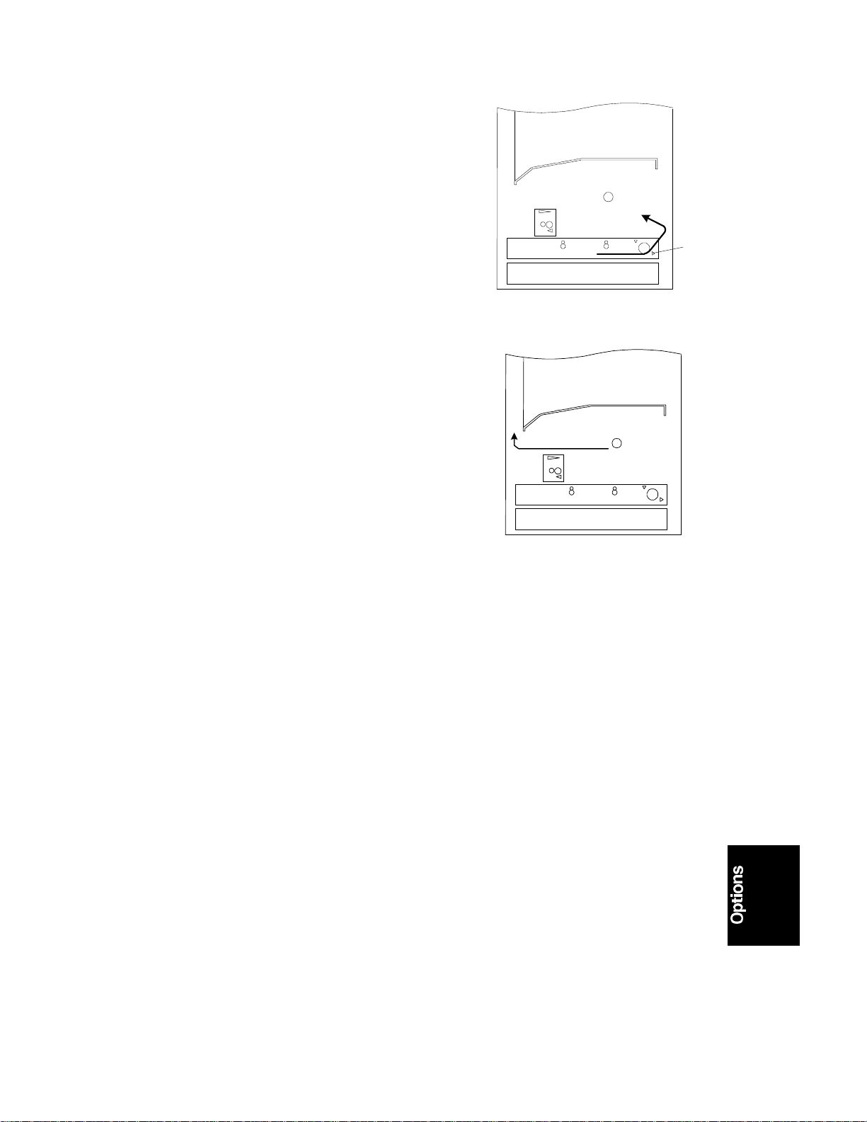
4.1 A3 PAPER SIZE
1. When the leading edge of the paper [A]
has passed through the fusing unit, the
junction gate solenoid energizes and the
junction gate [B] is opened. The paper is
guided to the inverter unit [C]. The on
timing of the junction gate solenoid is
controlled by the registration sensor.
2. The paper is fed to the duplex tray [D] by
the inverter unit transport roller [E], and
to the duplex feed roller [F] by the left
and central transport rollers ([G], [H]) in
the duplex tray. When the trailing edge of
the paper has passed through the duplex
entrance sensor [I], the speed of the
paper doubles.
[B]
[D]
[A]
[C]
G694O506.wmf
[E]
[F]
[I]
3. The paper is inverted by the duplex feed
roller [F]. The duplex feed motor turns off
shortly after the trailing edge of the paper
passes through the duplex turn sensor
[J].
[G] [H]
G694O507.wmf
[J]
G694O508.wmf
[F]
G694-6
Page 8
1 August 1996 BASIC OPERATION
4. Almost immediately after stopping, the
duplex feed motor turns on again in
reverse, and the inverted paper is fed
back to the copier. When the trailing
edge of the paper passes through the
duplex exit sensor [K], the duplex feed
motor turns off.
[K]
G694O509.wmf
5. The paper is transported to the exit area.
G694O521.wmf
G694-7
Page 9

BASIC OPERATION 1 August 1996
4.2 SHORTER THAN A4 LENGTHWISE (MEMORY COPY)
á
8 Original (
1. Two sheets of paper [A] [B] are fed from
the lower paper tray and the first paper
transported to the duplex tray in the
same way as for A3.
2. The first sheet [A] of paper is reversed by
the duplex turn roller and the second
sheet [B] is transported to the duplex unit
in the same way as for A3 size.
~ º)
[A]
2
G694O510.wmf
[B]
3. The first sheet [A] is fed out to the copier
from the duplex tray in the same way as
for A3 size. The transport motor stops
when the leading edge of the second
sheet [B] turns on the duplex turn sensor
[C]. The second sheet [B] stops in the
waiting position.
[B]
[B]
4
2
G694O511.wmf
[A]
[C]
4
2
G694O512.wmf
[A]
G694-8
Page 10

1 August 1996 BASIC OPERATION
4. The second sheet [B] starts again when
the trailing edge of the first sheet [A]
passes through the duplex exit sensor
[D], and it is reversed. The second sheet
is being reversed, the third sheet [E] is
fed out from the lower tray after the first
sheet has reached the registration roller.
[A]
1
2
4
[E]
[D]
5. The first sheet [A] is fed out to the copy
tray. The second sheet [B] is fed out from
the duplex tray. The third sheet [E] is
transported to the duplex tray.
6. The second sheet [B] is transported to
the exit section. The third sheet [E] is
reversed. While the third sheet is being
reversed, the fourth sheet [F] is fed out
from the lower tray after the second
sheet [B] has reached the registration
roller.
[A]
2
1
[E]
[B]
6
3
4
G694O513.wmf
4
G694O514.wmf
[B]
[B]
[F]
G694-9
[E]
6
G694O515.wmf
Page 11

BASIC OPERATION 1 August 1996
7. The second sheet [B] is fed out to the
copy tray. The third sheet [E] is fed out
from the duplex tray. The fourth sheet [F]
is transported to the duplex tray.
8. The third sheet [E] is transported to the
exit section. The fourth sheet [F] is
reversed.
[F]
[B]
4
3
8
6
G694O516.wmf
[E]
[E]
5
6
8
[F]
9. The third sheet [E] is fed out to the copier
exit tray. The fourth sheet [F] is fed out
from the duplex tray.
[E]
G694O517.wmf
6
5
8
G694O518.wmf
[F]
G694-10
Page 12

1 August 1996 BASIC OPERATION
10. The fourth sheet [F] is transported to the
exit section.
7
8
[F]
G694O519.wmf
11. The fourth sheet [F] is fed out to the
copier exit tray.
[F]
8
7
G694O520.wmf
G694-11
Page 13

DETAILED DESCRIPTIONS 1 August 1996
5. DETAILED DESCRIPTIONS
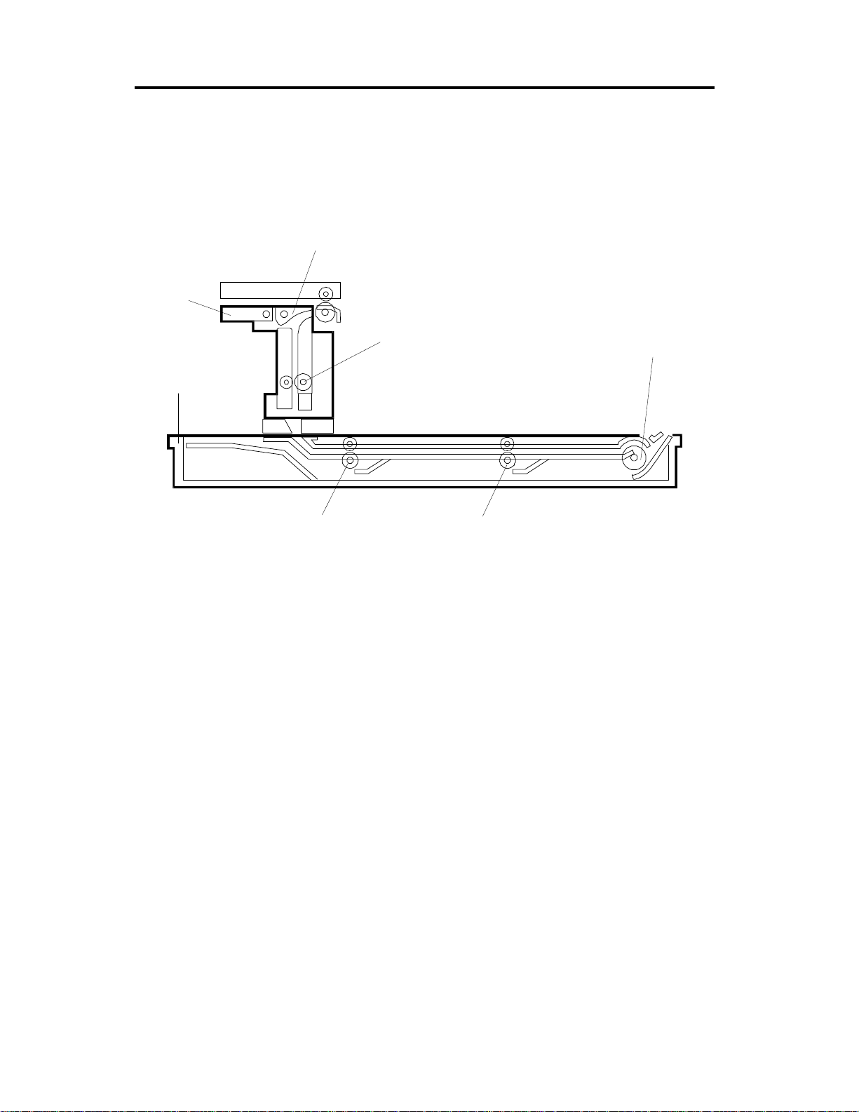
5.1 DUPLEX JUNCTION GATE MECHANISM
[A]
[C]
[B]
To the inverter
G694O007.wmf
The paper that is fed out from the fusing unit [A] is delivered to the copier exit
section or to the inverter unit.
When the duplex junction gate solenoid [B] energizes, the junction gate [C]
opens, and the paper is fed to the inverter unit.
G694-12
Page 14

1 August 1996 DETAILED DESCRIPTIONS
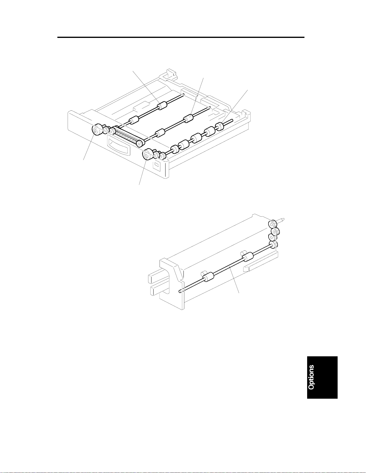
5.2 PAPER TRANSPORT AND FEED MECHANISM
[B]
[C]
[E]
[A]
[D]
G694O004.wmf
[B]
[C]
[F]
G694O008.wmf
The duplex transport motor [A] drives the left and central transport rollers ([B],
[C]) and the duplex feed motor [D] drives the duplex feed roller [E].
The paper sent from the inverter unit is fed by the left and central transport
rollers to the duplex feed roller.
The duplex feed roller inverts the paper. The duplex feed roller stops shortly
after the trailing edge of the paper turns off the duplex turn sensor [F].
Immediately after this, the duplex feed roller [E] turns in reverse and the
inverted paper is fed out to the copier.
G694-13
Page 15

DETAILED DESCRIPTIONS 1 August 1996
5.3 TIMING CHARTS
5.3.1 A3 (without memory)
G694-14
G694O500.wmf
Page 16

1 August 1996 DETAILED DESCRIPTIONS
5.3.2 A4 sideways (Memory)
G694-15
G694O501.wmf
Page 17

DETAILED DESCRIPTIONS 1 August 1996
5.4 OVERALL ELECTRICAL CIRCUIT
Copier IOCSS
Board
Duplex Tray
Duplex Control Board
Motors
Duplex Tray
Connection
Sensors
Solenoid and
Sensor
Inverter Unit
A694O502.wmf
The solenoid and sensor in the inverter unit are directly connected to the
copier. The motors and sensors in the duplex tray are controlled by the
duplex control board.
When the duplex tray connector is connected (this happens when the duplex
tray is slid into the machine), the duplex tray connection signal to the copier is
grounded. Then the copier detects that the duplex tray has been inserted.
G694-16
Page 18

1 August 1996 DIP SWITCHES
6. DIP SWITCHES
6.1 DUPLEX CONTROL BOARD : DSW1
SW No. Function
1
Adjustment Value
2
3Free Run
4 Adjustmen t Di r ect i on
SW1 SW2 Value
OFF OFF 0 mm
ON OFF 2 mm
OFF ON 4 mm
ON ON 6 mm
SW4
ON: [–] direction
OFF: [+] direction
[A]
G694O505.wmf
Adjustment of the paper stop position at the duplex feed roller [A]
(SW1,2,4)
If paper jams occur after changing the duplex turn sensor, because the
sensor was not installed correctly, adjust the paper stop position at the
duplex feed roller [A].
Free run (SW3)
The duplex transport and feed motor turn on with A4 sideways timing.
G694-17
Page 19

REPLACEMENT AND ADJUSTMENT 1 August 1996
7. REPLACEMENT AND ADJUSTMENT
7.1 DUPLEX TRANSPORT UNIT REMOVAL
[B]
[D]
[A]
[C]
G694O503.wmf
1. Remove the inner cover [A] of the duplex tray (2 screws).
2. Remove the duplex control board cover [B] (2 screws).
3. Release the hook and remove the front cover [C].
4. Remove the duplex transport unit [D] (4 screws, 4 connectors).
G694-18
Page 20

1 August 1996 REPLACEMENT AND ADJUSTMENT
7.2 DUPLEX TRANSPORT AND FEED MOTOR REPLACEMENT
[C]
[A]
[B]
G694O504.wmf
1. Remove the transport unit.
2. Replace the duplex transport motor [A] (2 screws, 1 connector).
Replace the duplex feed motor [B] (2 screws, 1 connector).
7.3 DUPLEX TURN AND DUPLEX EXIT SENSORS
1. Remove the duplex transport unit.
2. Replace the duplex turn sensor [C] (1 connector).
Replace the duplex exit sensor [D] (1 connector).
[D]
G694-19
Page 21

REPLACEMENT AND ADJUSTMENT 1 August 1996
7.4 DUPLEX JUNCTION GATE SOLENOID AND DUPLEX
ENTRANCE SENSOR REPLACEMENT
[A]
[C]
[B]
G694O012.wm f
1. Remove the inverter unit [A] (1 screw).
2. Replace the junction gate solenoid [B] (2 screws, 1 connector)
Replace the duplex entrance sensor [C] (1 connector).
G694-20
Page 22

1 August 1996 COPIER INSTALLATION
DUPLEX UNIT INSTALLATION
[A]
G694I500.wmf
[C]
G694I508.wmf
[B]
[D]
G694I502.wmf
CAUTION
Unplug the copier power cord before starting the following procedure.
1. Unpack the inverter unit and duplex unit and remove the tapes (7 tapes)
and two knob screws [A].
2. Open the front cover [B].
3. Slide the two hinges [C] inward and remove them as shown in the
illustration. Then, remove the front cover.
4. Remove the inverter unit cover [D] (1 screw).
3-13
Page 23

COPIER INSTALLATION 1 August 1996
[A]
G694I503.wmf
G694I504.wmf
[B]
G694I505.wmf
5. Swing the lower transport guide plate [A] down as shown in the illustration.
6. Remove the lower transport guide plate and pull it out as shown in the
illustration.
7. Push the inverter unit [B] in until the pin is completely inserted in the pin
hole.
8. Secure the inverter unit with the screw which was removed in step 4.
3-14
Page 24

1 August 1996 COPIER INSTALLATION
[B]
[A]
G694I506.wmf
[C]
[D]
G694I507.wmf
9. Swing the upper inverter guide plate [A] up as shown in the illustration
and secure it with the magnets [B] at front and rear.
10. Reinstall the front cover.
11. Pull out the 1st paper tray [C].
12. Push the duplex unit [D] into the place where the 1st paper tray was.
13. Turn the ac and main switches on and check if the duplex unit works
properly.
3-15
Page 25

Duplex (G694)
1
5
4
G694S500.wmf
2
3
6
7
G694S501.wmf
Page 26

Duplex (G694)
Symbol Index No. Description P to P (1/2)
Motors
M1 5 Duplex Transport B9
M2 4 Duplex Feed C9
Sensors
S1 7 Duplex Entrance B11
S2 2 Duplex Tur n C12
S3 3 Duplex Exit C12
Solenoid
SOL1 6 Duplex Junction Gate Control B11
PCBs
PCB1 1 Duplex Contr ol C11
 Loading...