

Page 1

FAX UNIT TYPE 250
- NEW -
(Machine Code: A804)
SERVICE MANUAL
Important Notices
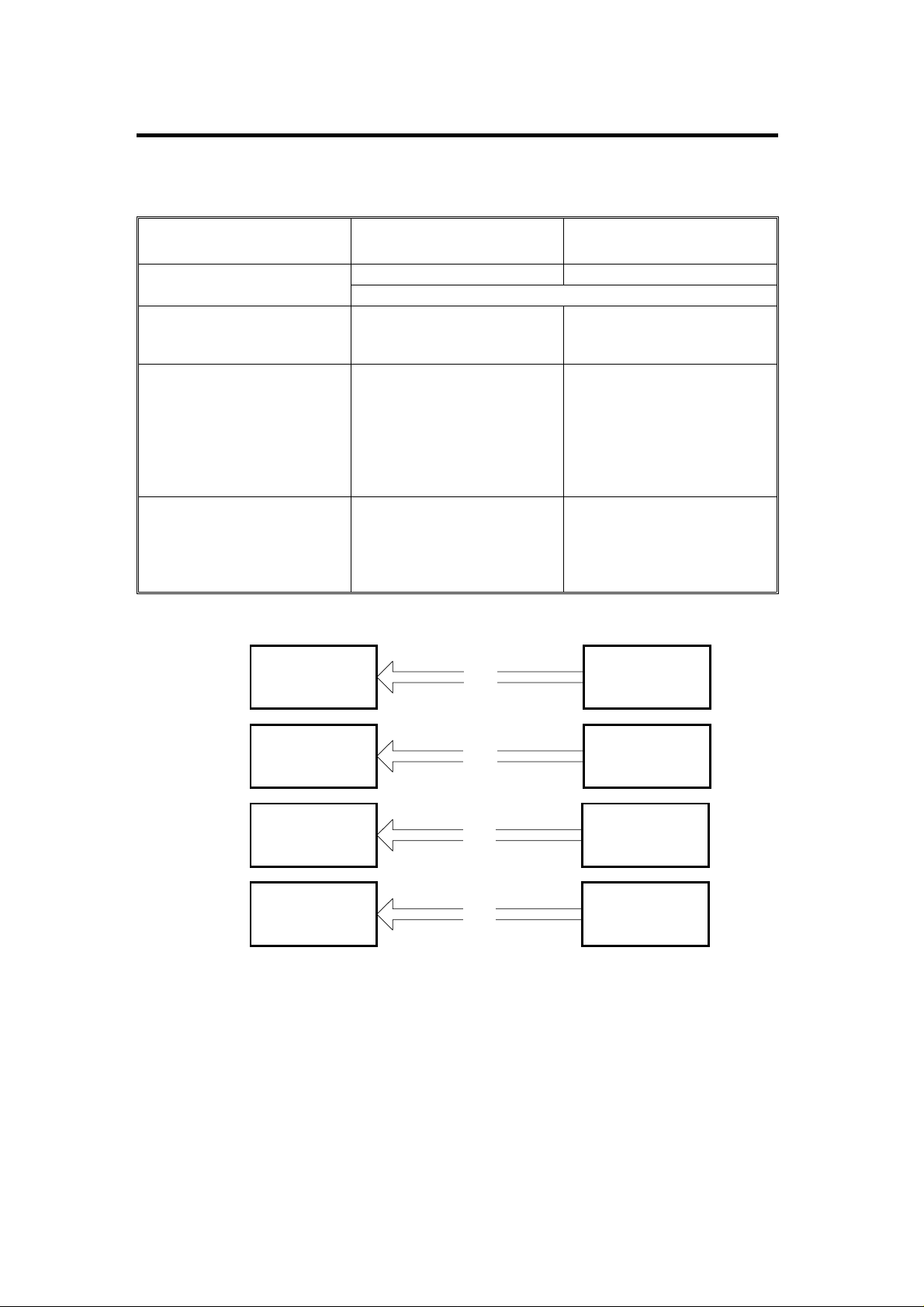
1. There are two types of FAX UNIT TYPE 250.
The existing one (machine code: A639) is only for the A193 copier, and
the new one (machine code: A804) is for the A193 and A224 copiers.
To prevent the existing type of fax unit from being installed in the A224
copier, carefully check the machine codes of the copier and the fax unit
before installation.
2. This manual describes only the diferential information between the
existing and new FAX UNIT TYPE 250, and information updated since
the A639 Fax Unit was released.
Page 2
May 12, 1997 OVERALL INFORMATION
1. OVERALL INFORMATION
1.1 SPECIFICATIONS
A639
(Existing Fax Unit)
Base Copier to be used with
Original Scan Speed
SAF Memory Capacity
(Measured usi ng an ITU-T
#1 Test Chart at Standard
resolution)
Options
A193 Copier A193 and A224 Copi er s
Refer to the diagram below for all possible combinations.
Standard: 1.6 s
Detail: 1.6 s
Fine: 3.3 s
Standard: 1MB (80 pages)
With 2MB option : 3MB ( 240
pages)
With 4MB option : 5MB ( 400
pages)
With HDD option: 80MB
(1200 pages )
Feature Expander
2M/4M/80M
Function Upgrade Card
400dpi Page Memory Card
ISDN G4
Possible Combinations and Results
A193
A
Copier
A804
(New Fax Unit)
Standard: 1.3 s
Detail: 1.3 s
Fine: 2.6 s
Standard: 2MB (160 pages)
With 2MB option : 4MB ( 320
pages)
With 4MB option : 6MB ( 480
pages)
With HDD option: 80MB
(1200 pages )
Same as A639 Fax Unit.
A639
OK
Fax Unit
B
C
D
A224
Copier
A193
Copier
A224
Copier
NG
A639
Fax Unit
A804
OK
Fax Unit
A804
OK
Fax Unit
A804V501.wmf
1
Page 3
OVERALL INFORMATION May 12, 1997
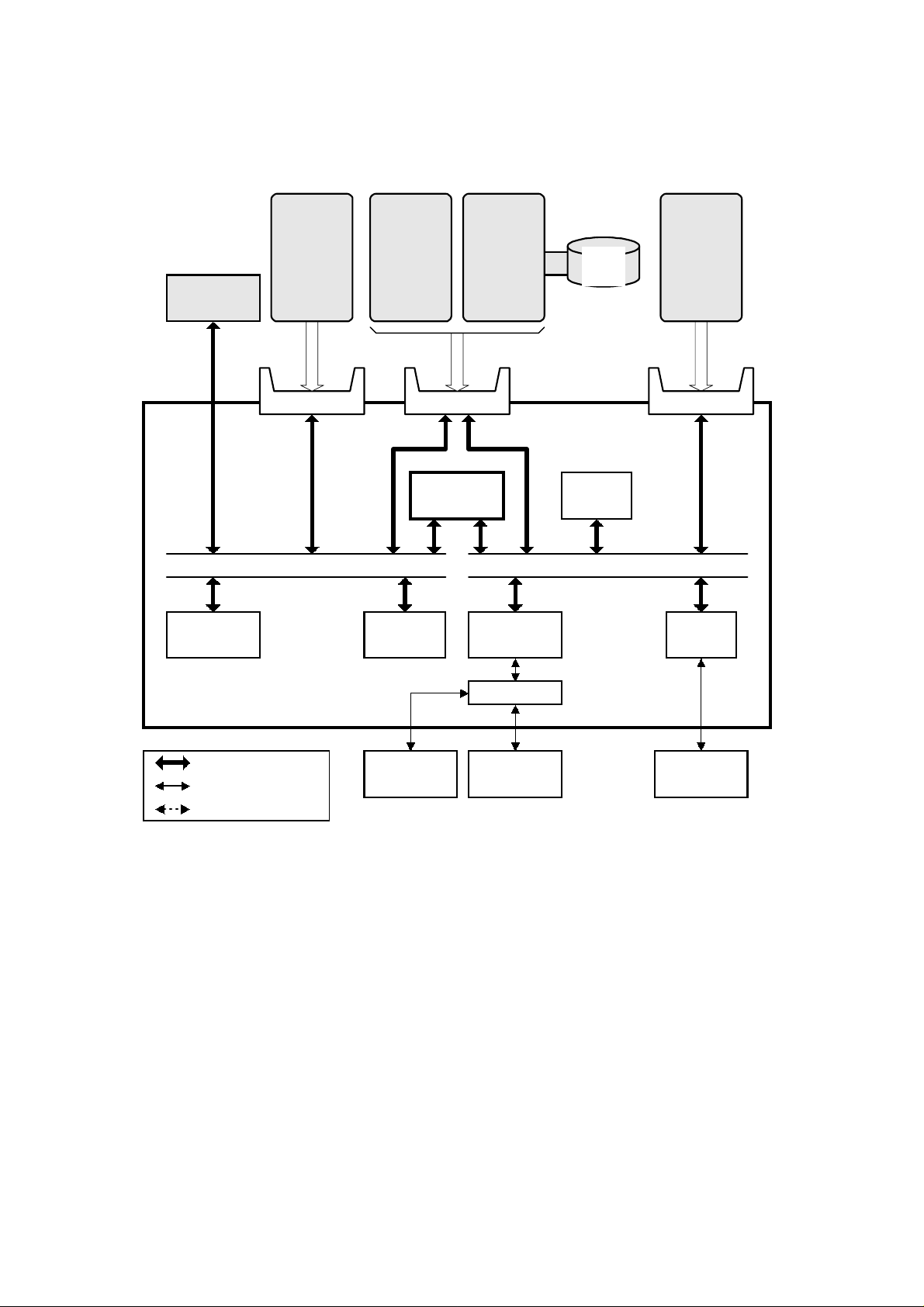
1.2 OVERALL MACHINE CONTROL
ISDN
G4
Flash ROM
(2MB)
Function
Upgrade
Card
Lower Left
CPU BUS
Feature
Expander
2M/4M
Upper Lower Right
SCP
SRAM
(128kB)
HDD
Interface
R144EFXL
Modem
80MB
HDD
DRAM
(3.5MB)
DMA BUS
Page
Memory
Card
VIF
Analog Circuit
FCU
Bus Interface
Parallel Interface
Serial Interface
Monitor
Speaker
NCU
BiCU
A804V500.wmf
The system block diagram is the same as the current A639 Fax Unit, except
for the following:
The DRAM size is increased to 3.5MB (SAF - 2MB, Page Memory -
•
1MB, ECM - 128kB, and Buffer - 384kB)
The clock speed used between VIF and BiCU is increased from
•
7.03MHz to 10.55 MHz.
2
Page 4

May 12, 1997 DETAILED DESCRIPTIONS
2. DETAILED DESCRIPTIONS
2.1 DOUBLE-SIDED ORIGINAL TRANSMISSION
This function becomes available with both A639 and A804 Fax Units if the
opptional Automatic Reverse Document Feeder (A661).
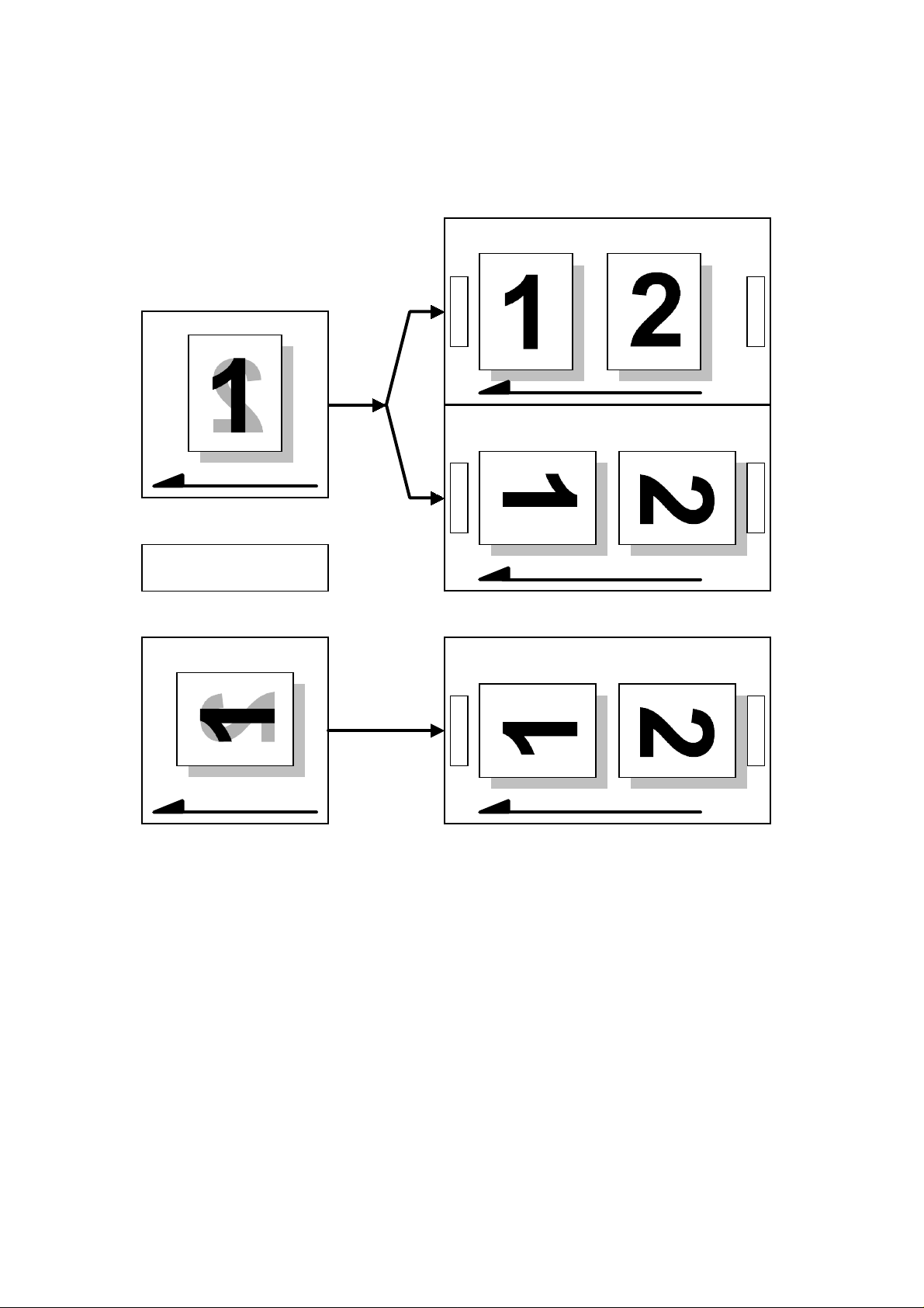
Using this function allows the machine to scan and transmit double-sided
originals. However, in some cases, the transmitted image orientations differ
between odd and even number pages, because of the ARDF switch-back
mechanism and the image rotation before transmision function.
The following diagrams show how images are transmitted in various cases.
However, the transmitted image may not be the same as the image printed at
the other end due to the receiver’s printing functions (e.g., image rotation
printing).
Cross Reference
Image Rotation On/Off - Scanner Switch 0F, bit 0
3
Page 5
DETAILED DESCRIPTIONS May 12, 1997
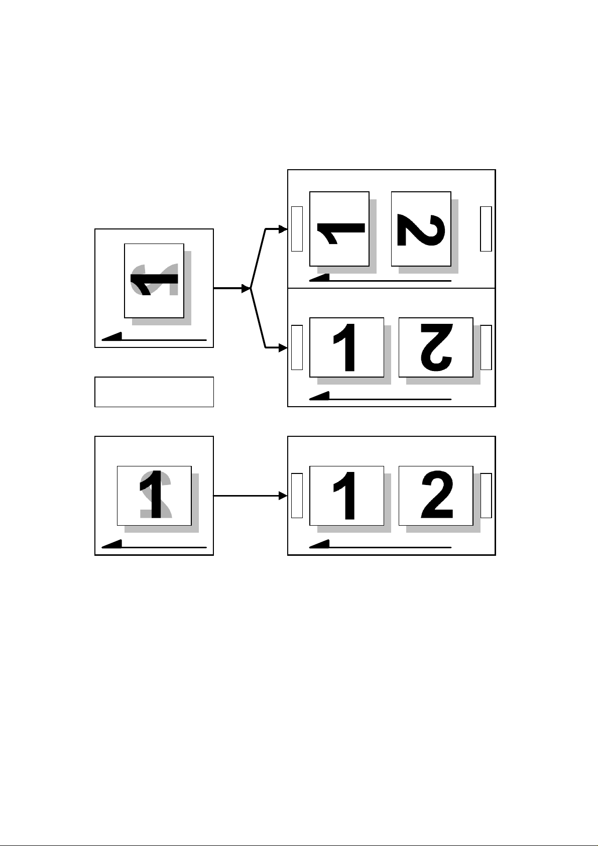
2.1.1 Portrait Original - Side Binding
Transmitted Image
Original
Feed-in Direction
- Front Side
Black
- Back Side
Gray
Original
Top
Top
Top
Bottom
Transmitted Image
(Rotated before Transmission)
Bottom
Transmitted Image
Bottom
Feed-in Direction
A804D501.wmf
4
Page 6
May 12, 1997 DETAILED DESCRIPTIONS
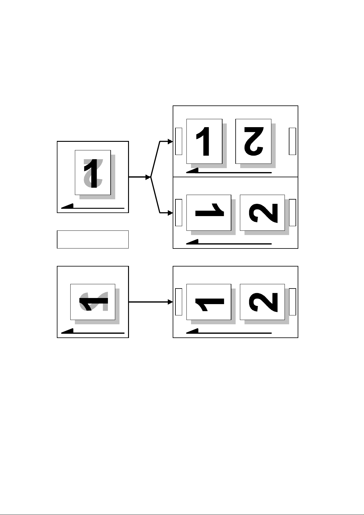
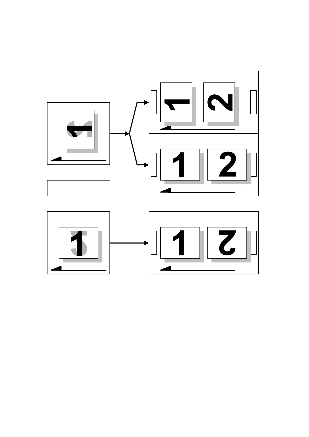
2.1.2 Portrait Original - Top Binding
Transmitted Image
Original
Feed-in Direction
- Front Side
Black
- Back Side
Gray
Original
Top
Top
Top
Bottom
Transmitted Image
(Rotated before Transmission)
Bottom
Transmitted Image
Bottom
Feed-in Direction
A804D502.wmf
5
Page 7
DETAILED DESCRIPTIONS May 12, 1997
2.1.3 Landscape Original - Side Binding
Transmitted Image
Original
Feed-in Direction
- Front Side
Black
- Back Side
Gray
Original
Top
Top
Top
Bottom
Transmitted Image
(Rotated before Transmission)
Bottom
Transmitted Image
Bottom
Feed-in Direction
A804D503.wmf
6
Page 8
May 12, 1997 DETAILED DESCRIPTIONS
2.1.4 Landscape Original - Top Binding
Transmitted Image
Original
Feed-in Direction
- Front Side
Black
- Back Side
Gray
Original
Top
Top
Top
Bottom
Transmitted Image
(Rotated before Transmission)
Bottom
Transmitted Image
Bottom
Feed-in Direction
A804D504.wmf
7
Page 9

DETAILED DESCRIPTIONS May 12, 1997
2.2 PAPER SIZE SELECTION PRI ORITIES
The following tables are updated from the A639 service manual.
Page Reduction
Reduction in Sub-scan Direction
Page Separation Threshold
Width or Length Priority Width
Disabled
Disabled
Received Image Size
A3 B4 A4
A3 B4 A4
1
11x17"
2
A4
8.5x11"
F/F4
11x17" F/F4
B5
B5
A4
A4
3
4
5
6
7
A4
8.5x11"
A3
8.5x14"
8.5x11"
A4 B5 A5
A4 B5 A5
A3
8.5x11"
A4 B5
8.5x11"
A3
F/F4
11x17"
A4
8.5x11"
A4
8.5x11"
B4
A4
8.5x11"
8.5x11"
8.5x11"
A4
A4
F/F4
8.5x14"
: Image Rotation
: Half of the page is blank
: Page Reduction
11x17" 8.5x11"8.5x14"
11x17" 8.5x14" 8.5x11"
A3 A4
8.5x11"
A4 A4
8.5x11"
A4
8.5x11"
8.5x11" F/F4
F/F4
A4
A4
F/F4
8.5x11"
8.5x14"
B4 A3 B4
F/F4
8.5x11"
F/F4
8.5x11"
8.5x11" 8.5x14"
A4
A3
11x17"
A4
8.5x11"
A4
A4
8.5x11"
F/F4
B4
8
Paper Select Priorities
8.5x14"
9
10
11
12
8.5x11"
F/F4
8.5x14"
Lengthwise
Sideways
B4
8.5x11"
11x17"
A5
B5
B5
B4
8.5x14"
F/F4
B5
A3 B5
11x17"
8.5x14"
11x17"
8
A3
B4
B4
8.5x14"
A3 B4 B4 A3
11x17" 11x17"
8.5x14" 11x17"
A5 A5 A5
B5 B5 B5
B5 B5 B5
A804D510.wmf
Page 10

May 12, 1997 DETAILED DESCRIPTIONS
Page Reduction
Reduction in Sub-scan Direction
Page Separation Threshold
Width or Length Priority Width
Disabled
Enabled
20 mm
Received Image Size
A3 B4 A4
A3 B4 A4
1
11x17"
2
A4
3
4
5
8.5x11"
6
F/F4
7
8
Paper Select Priorities
8.5x14"
9
A4
8.5x11"
B4
A3
11x17" F/F4
B5
B5
8.5x11"
A4
A4
8.5x11"
8.5x11"
A4 B5 A5
A4 B5 A5
A4
8.5x14"
11x17"
A4 B5
8.5x11"
8.5x11" 8.5x11"
A4
A3
A3
F/F4
11x17"
8.5x11"
B4
B4
8.5x14"
: Image Rotation
: Half of the page is blank
: Page Reduction
11x17" 8.5x11"8.5x14"
8.5x14" 8.5x11" F/F4
A3
11x17"
A4
8.5x11"
F/F4
B4
A4
8.5x11"
8.5x11"
B4 A3 B4
A3 B4 B4 A3
11x17" 11x17"
8.5x11"
B4
A4 A4
8.5x11"
A4
A4
A4
8.5x11" F/F4
F/F4
8.5x11"
8.5x14"8.5x11" 11x17"
F/F4
B5
A3 B5
8.5x14"
8.5x11"
A4
A4
F/F4
8.5x14"
F/F4
8.5x11"
A4
8.5x14"
A4
A4
8.5x11"
A4
8.5x11"
A3
F/F4
8.5x11"
8.5x14" 11x17"
10
11
12
F/F4
8.5x14"
Lengthwise
Sideways
A5
B5
B5
11x17"
8.5x14"
9
A3
B4
11x17"
A5 A5 A5
B5 B5 B5
B5 B5 B5
A804D511.wmf
Page 11

DETAILED DESCRIPTIONS May 12, 1997
Page Reduction
Reduction in Sub-scan Direction
Page Separation Threshold
Width or Length Priority Length
Disabled
Disabled
Received Image Size
A3 B4 A4
A3 B4 A4
1
11x17"
2
A4
8.5x11"
F/F4
11x17" F/F4
B5
A4
3
4
5
6
7
A4
8.5x11"
A3
8.5x14"
B5
A4
A4 B5 A5
A4 B5 A5
A3
B4
A4 B5
8.5x11"
A3
F/F4
11x17"
A4
11x17"
B4
8.5x11"
A4
A4
8.5x11"
8.5x11"
8.5x11"
A4
A4
F/F4
8.5x14"8.5x11"
: Image Rotation
: Half of the page is blank
: Page Reduction
11x17" 8.5x11"8.5x14"
8.5x14" 8.5x11" F/F4
11x17"
A3
B4
A4
A4
11x17"
A4
8.5x11"
8.5x11"
F/F4
A4
8.5x11"
8.5x11"
A4
A4
F/F4
8.5x14"
A3
F/F4
8.5x11"
8.5x11"
8.5x14"
8.5x11"
F/F4
B4A3
A3 A3
11x17" 11x17"
A4
B4
8.5x14"
A4
8.5x11"
8.5x11"
F/F4
8.5x14"
8.5x11"
8.5x11"
A5
B5
B5
B4
8
Paper Select Priorities
8.5x14"
9
10
11
12
Lengthwise
Sideways
B4
8.5x14"
F/F4
A3
11x17"
8.5x14"
A3
B4
11x17"
B5
B5
B4
8.5x14"
8.5x11"
F/F4
B4
11x17"
A4
A4
8.5x11"
A5 A5 A5
B5 B5 B5
B5 B5 B5
A804D512.wmf
8.5x11"
10
Page 12

May 12, 1997 DETAILED DESCRIPTIONS
Page Reduction
Reduction in Sub-scan Direction
Page Separation Threshold
Width or Length Priority Length
Disabled
Enabled
20 mm
Received Image Size
A3 B4 A4
A3 B4 A4
1
11x17"
2
A4
8.5x11"
F/F4
11x17" F/F4
B5
B5
A4
A4
3
4
5
6
7
A4
8.5x11"
A3
A4 B5 A5
A4 B5 A5
A3
B4
A4 B5
8.5x11"
A3
F/F4
11x17"
A4
8.5x14"
11x17"
B4
8.5x11"
A4
A4
8.5x11"
8.5x11"
8.5x11"
A4
A4
F/F4
8.5x14"8.5x11"
: Image Rotation
11x17" 8.5x11"8.5x14"
8.5x14" 8.5x11" F/F4
A3
11x17"
B4
A4
A4
11x17"
A4
8.5x11"
8.5x11"
F/F4
A4
8.5x11"
: Half of the page is blank
: Page Reduction
F/F4
8.5x11"
A4
8.5x14"
A4
8.5x11"
A4
A4
F/F4
8.5x14"
A3
8.5x11"
F/F4
11x17"
8.5x11"
A3
B4A3
A3
11x17"
A4
A4
8.5x11"
8.5x11"
F/F4
8.5x14"
8.5x11"
8.5x11"
A5
B5
B5
B4
8
Paper Select Priorities
8.5x14"
9
10
11
12
Lengthwise
Sideways
B4
8.5x14"
F/F4
A3
11x17"
8.5x14"
A3
B4
11x17"
B5
B5
B4
8.5x14"
B4 B4
8.5x11"
F/F4
8.5x11"
8.5x14"11x17"
A5 A5 A5
B5 B5 B5
B5 B5 B5
A801D513.wmf
8.5x11"
11
Page 13

DETAILED DESCRIPTIONS May 12, 1997
Page Reduction
Reduction in Sub-scan Direction
Page Separation Threshold
Width or Length Priority Width
Enabled
Enabled
20 mm
Received Image Size
A3 B4 A4
B4 A4
A3
1
11x17"
2
3
A4
4
A4
5
6
8.5x11"
7
F/F4
8
Paper Select Priorities
B4
8.5x11"
A4
A4
8.5x14"
F/F4
8.5x14"
8.5x11" F/F4
A3
11x17"
B5
A4 B5 A5
A4
A3
8.5x11"
B4
A4
8.5x11"
A3
F/F4
11x17"
B4
A4
F/F4
B5 A5
8.5x11"
A4
11x17" 8.5x11"8.5x14"
A3
8.5x11"
B5
B4
A4
8.5x11"
F/F4
11x17"
B4
8.5x11"
A4
A4
A4
8.5x14"8.5x11"
B5
A4
F/F4 8.5x14"
8.5x11"
8.5x11"
F/F4
: Image Rotation
: Half of the page is blank
: Page Reduction
F/F4
8.5x11"
8.5x14" 8.5x11" F/F4
A4
A4
8.5x11"
8.5x11"
B4 B4
A3 A3
8.5x11"
A4
A4
F/F4
A3
B4
A4
A4
8.5x11"
8.5x11"
A3
F/F4
11x17"
B4
8.5x14"
A4
A4
8.5x11"
8.5x11"
9
10
11
12
8.5x14"
B5
8.5x11"
8.5x11"
Lengthwise
Sideways
11x17"
A5
B5
B5
8.5x14"
A3
11x17"
8.5x14"
B5
A3
B4
11x17"
8.5x14"
11x17"
11x17" 11x17"
A5 A5 A5
B5 B5 B5
B5 B5 B5
8.5x14"
A801D514.wmf
12
Page 14

May 12, 1997 DETAILED DESCRIPTIONS
Page Reduction
Reduction in Sub-scan Direction
Page Separation Threshold
Width or Length Priority Width
Enabled
Enabled
20 mm
Received Image Size
A3 B4 A4
B4 A4
A3
1
11x17"
2
3
A4
4
A4
5
6
8.5x11"
7
8
Paper Select Priorities
B4
8.5x11"
F/F4
A4
A4
8.5x14"
F/F4
8.5x14"
8.5x11" F/F4
A3
11x17"
B5
A4 B5 A5
A4
A3
8.5x11"
B4
A4
8.5x11"
A3
F/F4
11x17"
B4
A4
F/F4
B5 A5
8.5x11"
A4
11x17" 8.5x11"8.5x14"
A3
8.5x11"
B5
B4
A4
8.5x11"
F/F4
11x17"
B4
8.5x11"
A4
A4
A4
8.5x14"8.5x11"
B5
A4
F/F4 8.5x14"
8.5x11"
8.5x11"
F/F4
: Image Rotation
: Half of the page is blank
: Page Reduction
F/F4
8.5x11"
8.5x14" 8.5x11" F/F4
A4
A4
8.5x11"
8.5x11"
B4 B4
A3 A3
8.5x11"
A4
A4
F/F4
A3
B4
A4
A4
8.5x11"
8.5x11"
A3
F/F4
11x17"
B4
8.5x14"
A4
A4
8.5x11"
8.5x11"
9
10
11
12
8.5x14"
B5
8.5x11"
8.5x11"
Lengthwise
Sideways
11x17"
A5
B5
B5
8.5x14"
A3
11x17"
8.5x14"
B5
A3
B4
11x17"
8.5x14"
11x17"
11x17" 11x17"
A5 A5 A5
B5 B5 B5
B5 B5 B5
8.5x14"
A804D515.wmf
13
Page 15

INSTALLATION May 12, 1997
3. INSTALLATION
NOTE:
1. Never install telephone wiring during a lightning storm.
2. Never install telephone jacks in wet locations unless the jack is
specifically designed for wet locations.
3. Never touch uninsulated telephone wires or terminals unless the
telephone line has been disconnected at the network interface.
4. Use caution when installing or modifying telephone lines.
5. Avoid using a telephone (other than a cordless type) during an
electrical storm. There may be a remote risk of electric shock
from lightning.
6. Do not use the telephone to report a gas leak in the vicinity of the leak.
CAUTION
+
1. Before installing the fax unit, switch off the main and ac switches,
and disconnect the power cord.
2. The fax unit contains a lithium battery. The danger of explosion
exists if a battery of this type is incorrectly replaced. Replace only
with same or an equivalent type recommended by the
manufacturer. Discard used batteries in accordance with the
manufacturer’s instructions
[B]
[A]
[D]
[Z]
[C]
A804I510.wmf
A804I500.wmf
1. Remove the rear cover [A] (6 screws), replace the current NCU cover [B]
with the new NCU cover [C], and attach the FCC/IC label (US only) or the
BABT label (UK only) [Z].
2. Remove screw [D] then remove the small cover [E].
[E]
14
Page 16

May 12, 1997 INSTALLATION
- For the A224 Copier only -
[b]
[a]
A804I530.wmf
A804I531.wmf
a. Remove the operation panel [a] as shown (3 screws; 1 harness).
b. Install the speaker unit [b] as shown (1 bracket with 2 screws; 1 harness).
c. Put back the operation panel [a] (3 screws; 1 harness).
- For the A193 Copier only -
[e]
[c]
A804I532.wmf
A804I533.wmf
a. Remove the harness [c] from the fax unit as shown.
b. Install the speaker unit [d] in the fax unit [e] as shown (1 ring shaped
bracket [f] with 3 screws; 1 harness).
[d]
[f]
15
Page 17

INSTALLATION May 12, 1997
[I]
[J]
[H]
[G]
[F]
[I]
[K]
A804I501.wmf
[O]
[Q]
[L]
[N]
[P]
[R]
[S]
[U]
[M]
A804I502.wmf
[T]
[V]
[a]
[d]
[a]
A804I527.wmf
[b]
[e]
[c]
A804I503.wmf
A804I528.wmf
A804I525.wmf
16
A804I534.wmf
Page 18

May 12, 1997 INSTALLATION
NOTE:
For European and Asian models only, perform steps a, b, and c.
a. Remove bracket [a] from the fax unit.
b. Remove screw [b] and install bracket [c] as shown.
3. Remove the inner bracket [F] (2 screws).
4. Turn on the battery switch [G]. Install the fa x unit [H] (4 screw s), as sho wn.
5. Connect the flat harness [I] to the BiCU (CN304), and connect the
harness [J] to the PSU (CN288).
c. Replace bracket [a] which was removed in step [a]; and install small
brackets [d] and [e].
NOTE:
Use a magnetic screwdriver so as not to dr op any screws inside th e machine.
6. Replace the rear cover (5 screws).
7. Remove the parts [K], [L], and [M] from the operation panel.
8. Peel off the decal [N] as shown, then remove part [O].
9. Install each part, [P], [Q] and [R] on the operation panel, as shown.
10. If the machine has the printer controller option, install the keys [S] and the
decal [T] as shown. The decal [T] has “Copy,” “Printer,” and “Facsimile”
printed on it.
If the machine does not have the printer controller option, install the
keys [U] and the decal [V] as s hown. The decal [V] has “Co py” and
“Facsimile” printed on it.
17
Page 19

INSTALLATION May 12, 1997
[W]
A804I523.wmf
11. Install the Stamper [W] into the ADF as shown.
12. Open the bypass feeder and attach the enclosed serial number label on
the metal frame.
13. Plug in the machine and turn on the ac and main switches.
14. Press the ’Facsimile’ key and check that the
facsimile LED lights. At this time, the
A804I520.img
following message should be shown:
NOTE:
1) This is not a functional problem. The machine shows this
message only when the fax unit is installed for the first time.
2) If “SC681” is shown on the display instead of “SC1201”, the old
type of fax unit is installed in the A224 copier. Refer to section
5.1 for details.
15. Press “Yes” to initialize the fax unit.
16. Connect the telephone cable to the "LINE" jack at the rear of the machine.
17. Set up and program the items required for fax communications, as shown below.
If the user function keys (F1, F2, F3 and F4) need to be programmed, affix the
enclosed label above the function keys.
The default settings of the user function keys are as follows:
F1 - Start Manual Rx
F2 - TEL Mode
F3 - Tx Result Display
F4 - Not programmed
18
Page 20

May 12, 1997 INSTALLATION
17. US only: If the optional handset needs
to be installed, use the bracket and
screws which are enclosed with the fax
unit.
[X]
18. In European countries where the usage
of the RJ11 type ’TEL’ jack is prohibited
by the local PTT, use the plug [X] in the
’TEL’ jack as shown.
Be sure to set the clock (date
NOTE:
•
A804I524.wmf
and time).
Program the serial number into the fax unit (service function 10).
•
The serial number can be found on the serial number label (which
has been attached to the machine in step 12).
3.1 INITIAL PROGRAMMING
Key-operator Level
Clock Key-operato r m ode 19
Transmit mode Initial setup (Transmit)
Resolution Initial setup (Transmit)
Photo original Initial setup (Transmit)
Reception mode Initial setup (Receive)
Auto image density Initial setup (Receive)
ID code Key-operato r m ode 01
ECM Key-operator mode 02
Volume Key-operator mode 09
TTI / RTI Key-operator mode 11
Economy transm i ssion Key-operator m ode 12
G3 setting (Analog line)
(Line type/CSI/Own number)
User parameters Key-operator mode 17
Key-operator m ode 14
19
Page 21

INSTALLATION May 12, 1997
Service Level
NCU country code (NCU parameter C.C.) Function 06 - 2
Bit switch count r y code (System switch 0F) Function 01 - 1
Local dia ling requ irements
(Communication switch 06)
Local proto col requirements (G3 sw i t ch 0B) Function 01 - 5
PBX access code (RAM ad dr ess 4800BB) Function 06 - 1
Machine ’ s serial nu m ber Function 10
Service station’s fax number Function 09
PM call (Syste m switch 01- bit 0) Function 01 - 1
Periodic service call
(RAM address 480379 - 48037D)
Function 01 - 4
Function 06 - 1
20
Page 22

May 12, 1997 SERVICE TABLES AND PROCEDURE
4. SERVICE TABLES AND PROCEDURE
4.1 BIT SWITCHES
This section describes only the updated switches. The updated switches are
marked with an asterisk.
4.1.1 System Switch
System Switch 1F
No FUNCTION COMMENTS
Not used Do not change the settings.
0
1
Printing a report after a jam
2*
or memory o ver f l ow occurred
during memory tx
Enabled
0:
Disabled
1:
Received fax pr i nt st art timing
3
(G3 recepti on)
After re ceiving each page
0:
After receiving all pages
1:
Received fax pr i nt st art timing
4
(G4 recepti on)
After re ceiving each page
0:
After receiving all pages
1:
Not used Do not change the fact or y settings.
5
6
Action when a fax SC has
7
occurred
Automatic reset
0:
SC code display
1:
(Bit 2 has been defined.)
The machine pr i nt s a M emory Storage Repo rt
0:
(Memory Tx) or a Transmission Result Report, if a jam
or memory overflow occurred while storing a document
into memory.
The machine does not print a report in the above
1:
conditions.
0: The machi ne pr i nt s each page immedi at el y af t er the
machine receives it.
The machine pr i nt s t he complete messag e af ter the
1:
machine re cei ves all the pages in the memory.
When the fax unit detects a fax SC code other than
0:
SC1201 and SC17 01, the fax unit automatically resets
itself.
When the fax uni t det e ct s any fax SC code, the fax
1:
unit displa ys t he SC code and stops.
Cross Reference
Fax SC codes - See “T ro ubl eshooting”
21
Page 23

SERVICE TABLES AND PROCEDURE May 12, 1997
4.1.2 Printer Switch
Printer Switch 0E
No FUNCTION COMMENTS
Paper size selection priority
0
Width
0:
Length
1:
Paper size selected for
1
printing A4 width fax data
8 x 11" size
0:
A4 size
1:
Page separation
2
Enabled
0:
Disabled
1:
Type of imag e printed on
3*
reports
Upper half
0:
50% reduction
1:
Not used Do not change the settings.
4
to
6
Equalizing the reduction rate
7
among separated pages
(Page Separation)
Enabled
0:
Disabled
1:
(Bit 3 has been defi ned additionally )
A paper size whic h has the same width as the
0:
received data i s selected first.
A paper size whic h has enough length to print all the
1:
received lines without reduction is selected first.
This switch determines which paper size is selected for
printing A4 wi dt h fa x dat a, w hen the machine has A4
and 8" x 11" size paper at the same time .
If all paper size s i n th e machine require p age
1:
separation to print a received fax message, the machine
does not prin t the message (Substit ut e R eception is
used).
After a larger size of paper is set in a cassette, the
machine automatically prints t he fax message.
The upper half of the i mage is printed on the reports
0:
unreduced.
The image is printed reduced by 50% in the sub-scan
1:
direction.
Even if “50% reduction” is selected, the transfer
Note:
result report will have the upper half of the image
unreduced.
All the pages are reduced with the same reduction
0:
ratio, when page separation has taken place.
Only the last page is reduced to fit the selected paper
1:
size when the page separation has ta ken place. Other
pages are pri nt ed w i t hout reduction.
4.2 RAM ADDRESSES
4800AA(H) - User parameter switch 10 (SWUSR_0A)
Bit 0: Not used
Bit 1: 2 into 1 0: Off, 1: On
Bit 2*: Paper selection priority for A4 documents 0: A3, 1: B4
Bit 3: Page reduction 0: Off, 1: On
Bits 4 to 7: Not used
22
Page 24

May 12, 1997 TROUBLESHOOTING
5. TROUBLESHOOTING
5.1 SC681 (A224 Copier only)
The copier shows “SC681” on the display in either of the following cases.
A224 Copier
A
SC681
A639
Fax Unit
A224 Copier
B
SC681
A804
Fax Unit
A. The A639 Fax Unit is installed in an A224 copier.
B. The A804 Fax Unit installed in the A224 copier is booted up from the
external A639 ROMs.
In these cases, the A224 copier shows SC681 when A639 Fax software is
detected at power-on. To fix this problem, turn off the machine and replace
the A) Fax Unit or B) ROMs with correct one(s).
A639
ROM
A804T501.wmf
23
Page 25

TROUBLESHOOTING May 12, 1997
5.2 OTHER POSSIBLE CASES
5.2.1 Possible Cases and Results
Base Copier
Fax Unit Installed Software A193 A224
A639 A639
A804
A804 A639
A804
5.2.2 When A804 Software is Downloaded to the A639 Fax Unit
Because the A804 software is not designed to work in the A639 Fax Unit, if it
is downloaded to the A639 Fax Unit by mistake, the Fax Unit does not start
up at power-on. So, the base copier machine cannot recognise the presence
of the fax unit in this case. No fax functions are available.
No problem SC681
See section 5.1.
Fax Unit not det ect ed.
See sect ion 5.2. 2.
See sect ion 5.2. 3 SC681
No problem No problem
Fax Unit not detected.
See section 5.2.2.
See section 5.1.
To fix this problem, download the correct A639 software to the fax unit using
the ROM board. All the programmed data remain the same as before after
software download, because no RAM initialization is made when the wrong
software is downloaded.
5.2.3 When A639 Software is Downloaded to the A804 Fax Unit
The A639 software works in the A804 Fax Unit if the Fax Unit is installed in
the A193 copier. However, the standard SAF memory capacity is limited to
1MB because of software limitations.
This does not look like a problem, but is not recommended. So, if A639
software was downloaded to an A804 Fax Unit by mistake, download the
correct A804 software to the fax unit using the ROM board.
24
 Loading...