

Page 1

Operating Instructions
Read this manual carefully before you use this machine and keep it handy for future reference. For safe and correct use, be sure to read "Safety Information"
before using the machine.
Page 2

Page 3
How to Read This Manual
Symbols
The following set of symbols is used in this manual.
Indicates a situation that may result in malfunction if instructions are not followed. Be sure to read the
instructions.
Indicates supplementary relevant information.
Indicates where you can find further relevant information.
[ ]
Indicates the names of keys that appear on the computer screen.
Notes
Contents of this manual are subject to change without prior notice.
Certain options might not be available in some countries. For details, contact your local dealer.
Some illustrations in this manual might be slightly different from the machine.
Depending on which country you are in, certain units may be optional. For details, please contact your
local dealer.
About the Abbreviation
In these sheets, we use the term RC Gate as an abbreviation of Remote Communication Gate A2 for
@Remote office NX. Generally, "administrator" refers to the "RC Gate administrator," unless otherwise
specified in this Manual.
Screens
The explanations in this manual use screen images from Windows 7 and Internet Explorer 9.0. If you use
different OS, screen images may differ. However, you can perform the same steps.
1
Page 4
Manuals for This Equipment
The following manuals describe procedures to operate and maintain this equipment. For safe and
efficient operation of this equipment, all users should read and follow the instructions carefully.
Operating Instructions (this manual)
Provides all of the information on how to use this equipment. Perform the procedures in this manual
after you have completed the procedures in "Safety Information/Setup Guide".
Safety Information/Setup Guide
Provides the information on safe usage of this equipment and how to install/set up it.
• You need not perform the registration procedures explained in this manual if a customer engineer
has already registered your equipment. However, in order to operate and maintain the equipment,
you must read this manual carefully.
• Adobe Acrobat or Adobe Reader is necessary to view this manual in PDF format.
2
Page 5

Important
To the maximum extent permitted by applicable laws, in no event will the manufacturer be liable for any
damages whatsoever arising out of failures of this product, losses of data, or the use or non-use of this
product and operation manuals provided with it. You are responsible for taking protective measures
against computer viruses, worms, and other harmful software.
3
Page 6

Laws and Regulations
User Information on Electrical & Electronic Equipment
Users in the countries where this symbol shown in this section has been specified in national law on collection and treatment of E-waste
Our Products contain high quality components and are designed to facilitate recycling.
Our products or product packaging are marked with the symbol below.
The symbol indicates that the product must not be treated as municipal waste. It must be disposed of
separately via the appropriate return and collection systems available. By following these instructions
you ensure that this product is treated correctly and help to reduce potential impacts on the environment
and human health, which could otherwise result from inappropriate handling. Recycling of products
helps to conserve natural resources and protect the environment.
For more detailed information on collection and recycling systems for this product, please contact the
shop where you purchased it, your local dealer or sales/service representatives.
All Other Users
If you wish to discard this product, please contact your local authorities, the shop where you bought this
product, your local dealer or sales/service representatives.
For Turkey only
4
Page 7

Üretici:
Ricoh Company, Ltd.
8-13-1 Ginza,
Chuo-ku, Tokyo 104-8222 Japan
+81-36278-2111(English only/Sadece İngilizce)
Environmental Advice for Users
Users in the EU, Switzerland and Norway
Consumables yield
Please refer to either the User's Manual for this information or the packaging of the consumable.
Recycled paper
The machine can use recycled paper which is produced in accordance with European standard
EN 12281:2002 or DIN 19309. For products using EP printing technology, the machine can print
on 64 g/m2 paper, which contains less raw materials and represents a significant resource
reduction.
Duplex printing (if applicable)
Duplex printing enables both sides of a sheet of paper to be used. This saves paper and reduces
the size of printed documents so that fewer sheets are used. We recommend that this feature is
enabled whenever you print.
Toner and ink cartridge return program
Toner and ink cartridge for recycling will be accepted free of charge from users in accordance with
local regulations.
For details about the return program, please refer to the Web page below or consult your service
person.
https://www.ricoh-return.com/
Energy efficiency
The amount of electricity a machine consumes depends as much on its specifications as it does on
the way you use it. The machine is designed to allow you to reduce electricity costs by switching to
Ready mode after it prints the last page. If required, it can immediately print again from this mode.
If no additional prints are required and a specified period of time passes, the device switches to an
energy saving mode.
In these modes, the machine consumes less power (watts). If the machine is to print again, it needs
a little longer to return from an energy saving mode than from Ready mode.
5
Page 8
For maximum energy savings, we recommend that the default setting for power management is
used.
Products that comply with the Energy Star requirement are always energy efficient.
Note for the Battery and/or Accumulator Symbol (For EU countries only)
In accordance with the Battery Directive 2006/66/EC Article 20 Information for end-users Annex II,
the above symbol is printed on batteries and accumulators.
This symbol means that in the European Union, used batteries and accumulators should be disposed of
separately from your household waste.
In the EU, there are separate collection systems for not only used electrical and electronic products but
also batteries and accumulators.
Please dispose of them correctly at your local community waste collection/recycling centre.
Notes to users in the United States of America
Notes on lamp(s) inside this machine
Notes to users in the state of California
Perchlorate Material - special handling may apply. See: www.dtsc.ca.gov/hazardouswaste/
perchlorate
6
Page 9

TABLE OF CONTENTS
How to Read This Manual................................................................................................................................. 1
Symbols...........................................................................................................................................................1
Notes...............................................................................................................................................................1
About the Abbreviation..................................................................................................................................1
Screens............................................................................................................................................................1
Manuals for This Equipment...............................................................................................................................2
Important............................................................................................................................................................. 3
Laws and Regulations.........................................................................................................................................4
User Information on Electrical & Electronic Equipment............................................................................... 4
Environmental Advice for Users.................................................................................................................... 5
Note for the Battery and/or Accumulator Symbol (For EU countries only).............................................. 6
Notes to users in the United States of America............................................................................................6
1. About the RC Gate
What Can be Done with the RC Gate............................................................................................................11
Outline of the System....................................................................................................................................... 12
Notes on an Environment Using both IPv4 and IPv6................................................................................13
Guide to Equipment......................................................................................................................................... 14
Front.............................................................................................................................................................. 14
Back.............................................................................................................................................................. 15
About Options.................................................................................................................................................. 16
About the RC Gate Monitor............................................................................................................................ 17
Users of the RC Gate Monitor.....................................................................................................................17
To Start the RC Gate Monitor..................................................................................................................... 18
To Close the RC Gate Monitor................................................................................................................... 19
2. Setting up the RC Gate
Preparation for Use..........................................................................................................................................21
Specifying the Device Settings....................................................................................................................21
Checking Versions for CC Conformance...................................................................................................22
Settings on Installation..................................................................................................................................... 24
Date/Time Settings......................................................................................................................................24
Networking...................................................................................................................................................24
IEEE 802.1x Authentication Setting........................................................................................................... 24
Proxy Server Setting.....................................................................................................................................24
7
Page 10

Connect to @Remote System...................................................................................................................... 24
Permit @Remote Task Performance............................................................................................................ 25
Auto Discovery.............................................................................................................................................25
SNMP Access...............................................................................................................................................25
Add Device...................................................................................................................................................26
System Log....................................................................................................................................................26
Installation Completed.................................................................................................................................26
3. How to Configure and Check the Device
Screen Configuration.......................................................................................................................................27
Setting a Password.......................................................................................................................................28
Shutdown the RC Gate................................................................................................................................29
Display Icons................................................................................................................................................29
Sorting/Classifying Lists.............................................................................................................................. 31
Importing/Exporting the System Settings.......................................................................................................33
Importing a CSV File....................................................................................................................................33
Exporting a CSV File....................................................................................................................................33
Format of CSV Files..........................................................................................................................................35
Format of a Device List CSV File................................................................................................................. 35
Format of a Discovery Range CSV File...................................................................................................... 36
Format of a Security Log CSV File.............................................................................................................. 38
Format of a Shift Device Firmware Update Prohibited Period CSV File.................................................. 39
4. Device List
Device List Items................................................................................................................................................41
Checking Device Properties............................................................................................................................ 42
Displaying Device Properties...................................................................................................................... 42
Main Properties............................................................................................................................................42
Status Details................................................................................................................................................ 43
Counters........................................................................................................................................................47
Optional Properties......................................................................................................................................48
@Remote Properties.....................................................................................................................................49
Access Accounts.......................................................................................................................................... 50
Manually Performing Polling.......................................................................................................................50
8
Page 11

5. Discovery and Polling
Discovery and Polling...................................................................................................................................... 51
Add Device...................................................................................................................................................51
Manual Discovery........................................................................................................................................54
Access Profiles..............................................................................................................................................56
Configuring Access Accounts..........................................................................................................................59
Setting a SNMP Account............................................................................................................................ 59
Setting a Device Administrator Account.....................................................................................................59
Overwriting an Access Account................................................................................................................. 60
Deleting an Access Account....................................................................................................................... 60
Specifying Access Profiles............................................................................................................................... 61
SNMP........................................................................................................................................................... 61
Device Administrator................................................................................................................................... 61
Searching for Devices......................................................................................................................................62
Search the Device........................................................................................................................................62
Search the Device Again.............................................................................................................................63
Registering a Device to the RS Center System...........................................................................................64
Classifying Devices by Group Name.............................................................................................................65
6. System
System Settings................................................................................................................................................. 67
Setup.............................................................................................................................................................67
Server Settings..............................................................................................................................................72
Security......................................................................................................................................................... 78
Logs...............................................................................................................................................................79
Scheduled Tasks...........................................................................................................................................82
Activating the RC Gate.................................................................................................................................... 84
Activating......................................................................................................................................................84
Deactivating the Product............................................................................................................................. 84
7. @Remote
@Remote Settings............................................................................................................................................. 87
Connect to @Remote System...................................................................................................................... 87
Collect/Notify Managed Device Information.......................................................................................... 89
Permit @Remote Task Performance............................................................................................................ 91
9
Page 12

Device Access Information..........................................................................................................................92
Serial Number Acquisition.......................................................................................................................... 93
Auto Discovery.............................................................................................................................................94
Migration......................................................................................................................................................97
Device SSL Setting....................................................................................................................................... 98
Device Firmware Update............................................................................................................................ 99
Shift Device Firmware Update Prohibited Period................................................................................... 100
Save Call/Counter History.......................................................................................................................102
Checking the Firmware..................................................................................................................................104
Update Device Firmware..........................................................................................................................104
Update System Firmware..........................................................................................................................104
8. Appendix
Troubleshooting............................................................................................................................................. 105
The RC Gate LED display..........................................................................................................................105
Troubleshooting.........................................................................................................................................106
When Error Messages Appear................................................................................................................ 106
If Problems Described in Error Messages Persist.................................................................................... 109
When the Office or Devices are Moved................................................................................................. 109
Inquiry for Repair and Maintenance Services........................................................................................ 109
To Return the RC Gate.............................................................................................................................. 109
Error Codes................................................................................................................................................109
Specifications for the Main Unit................................................................................................................... 121
Information about Installed Software...........................................................................................................122
Trademarks.....................................................................................................................................................127
INDEX...........................................................................................................................................................129
10
Page 13

1. About the RC Gate
This chapter will describe the outline of the RC Gate.
What Can be Done with the RC Gate
The following operations are available using the RC Gate:
• Send an automatic service call notifying the RS Center System that a device has malfunctioned.
• Update device firmware.
• Obtain device counter information and send it to the RS Center System.
• Automatically report to the RS Center System to order new supplies, such as toner, when a device
indicates that its supplies are low.
• Quickly check the usage status of multiple devices.
11
Page 14
DJH013
1
2
333456
TCP/IP
Internet
1. About the RC Gate
Outline of the System
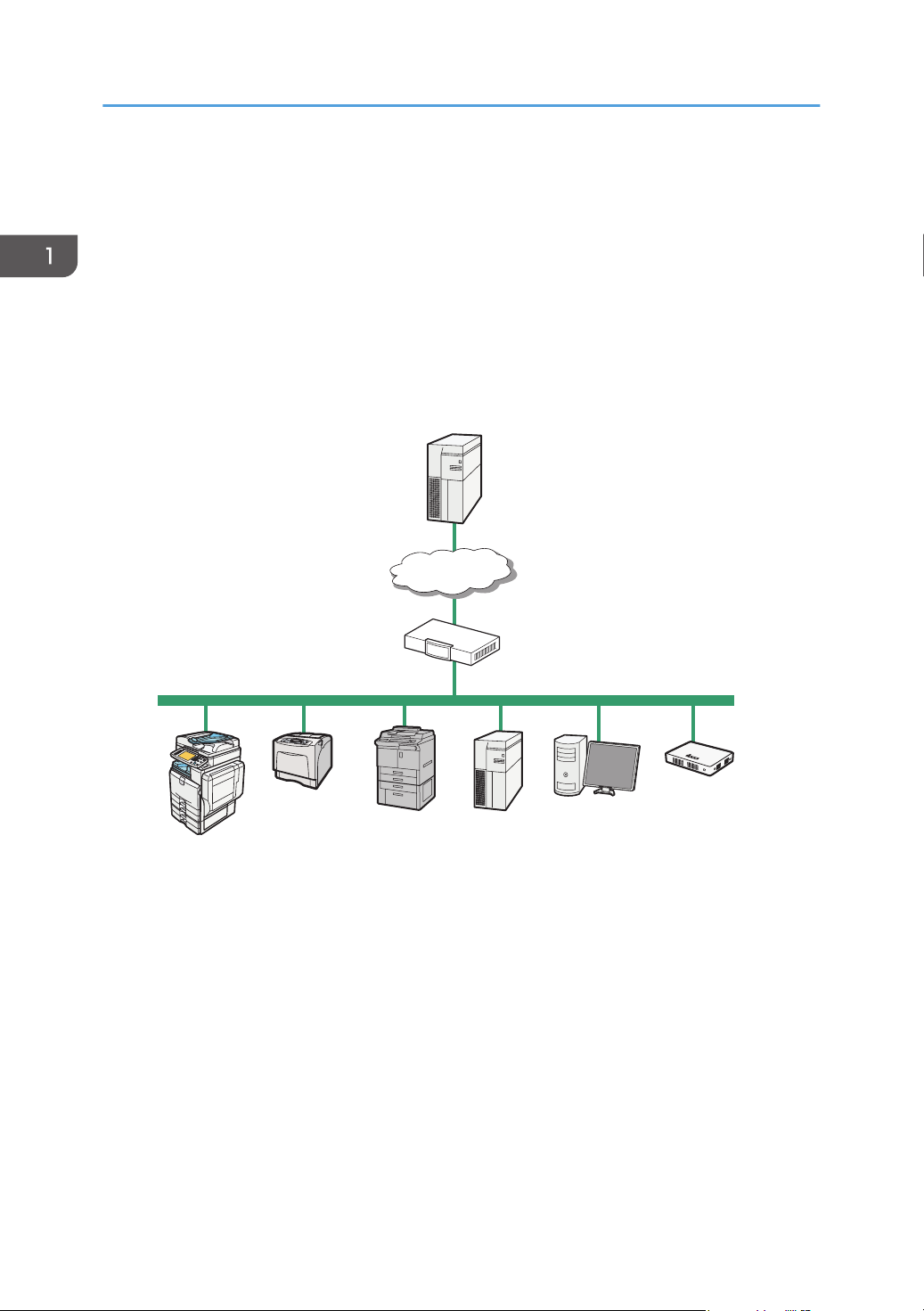
The RC Gate communicates with the RS Center System over the Internet using HTTPS. Authentication by
HTTPS ensures the security of communication between the RC Gate and the RS Center System.
The RS Center System serves as the HTTPS server, and the RC Gate works as the HTTPS client.
Communication is possible when the following conditions are satisfied:
• Your environment is arranged to be able to access Web sites outside of your network.
• The network setting is specified for a communication that may require a proxy server.
1. RS Center System
Information sent for various services will be aggregated to this server.
2. Proxy Server and/or Firewalls
You are able to use your proxy server and firewalls with this equipment. The proxy server can be used without
authentication or with Basic authentication, Digest authentication, Windows authentication, or Kerberos
authentication.
3. Device
A printer and multifunction machine can be managed by this equipment. This equipment can manage a
maximum of 100 devices.
12
Page 15

Outline of the System
• There are two types of devices managed by the RC Gate. One is compatible with HTTPS, and the other
is compatible with SNMP. The user can identify the type by selecting [@Remote Properties] on the
[Device List] and referring to [Connection Type].
• Mutual authentication in the HTTPS connection ensures the security of communication between the RC
Gate and an HTTPS-compatible device. As a requirement for HTTPS-compatible devices, [Do not
Prohibit] must be specified in [@Remote Service] under the Administrator Tools menu.
• SNMPv1/v2 or SNMPv3 can be used for communication between the RC Gate and SNMP-compatible
devices.
• TLS 1.0, TLS 1.1, and TLS 1.2 can be used to communicate between the RC Gate and TLS-compatible
devices.
If you have installed optional storage to expand the capacity, up to 1,000 devices can be registered. For
details, contact your service representative.
For option information, see page 16 "About Options".
4. Mail Server (SMTP Server)
This machine is equipped with the server to use e-mail notification.
5. Computer for Administration
You can manage this equipment by accessing the RC Gate Monitor via web browser. For details, see
page 17 "About the RC Gate Monitor".
6. This Equipment (RC Gate)
Intermediates the managed devices and the RS Center System. Sends the device information to the RS Center
System, and receives software to update the devices from the RS Center System.
Notes on an Environment Using both IPv4 and IPv6
This product supports the dual-stack environment of IPv4 and IPv6 while it does not support the
environment using a translator. In an environment using a translator, depending on the MFP or printer in
use, no communication with this product can be established.
If the no communication is possible between the device and the RC Gate, check whether the
environment supports the translator. For details, contact your service representative.
13
Page 16
12 5
3
4
DJH100
1. About the RC Gate
Guide to Equipment
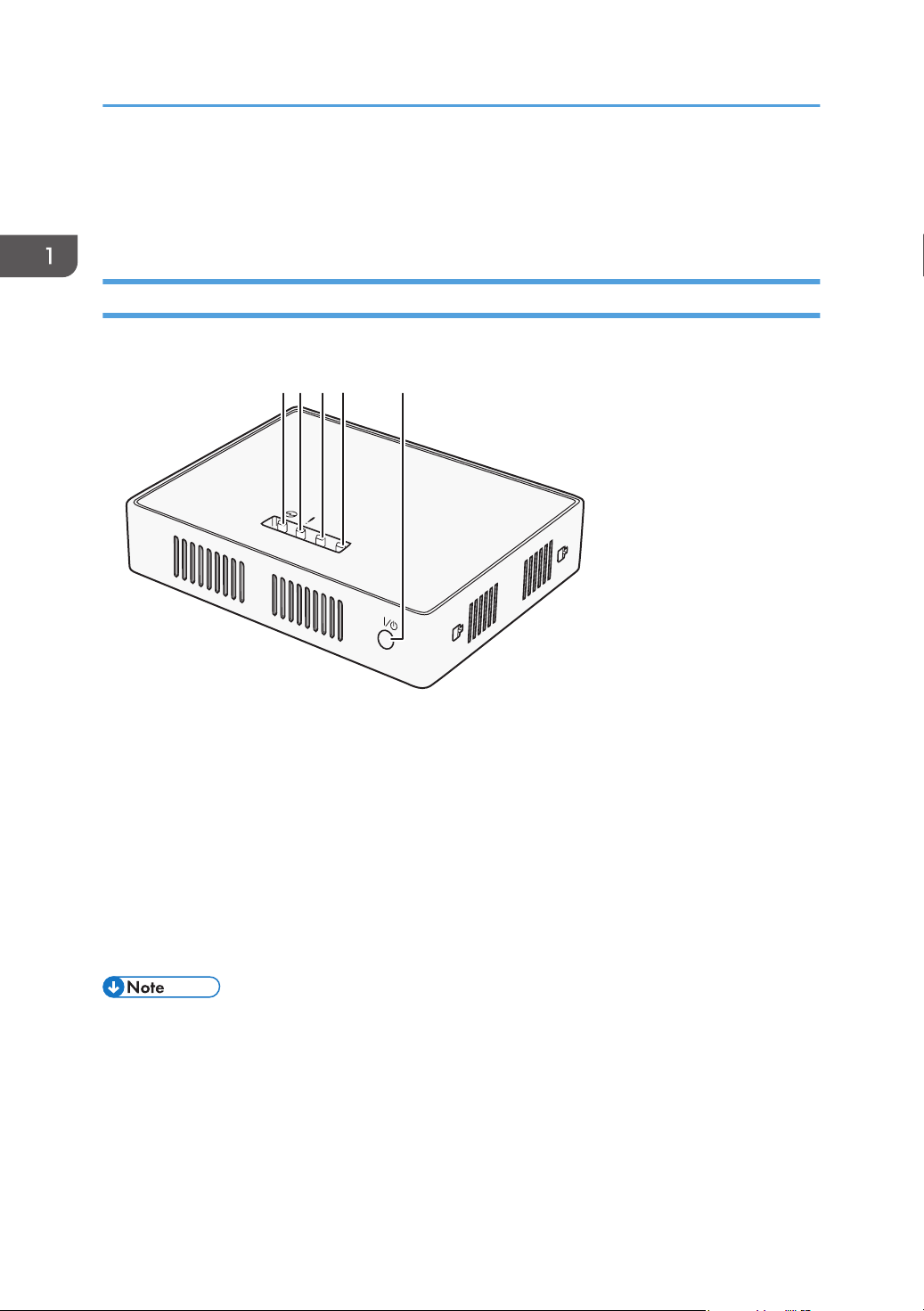
This section explains names and functions of each part.
Front
This section explains names and functions of the parts on the front side of the RC Gate.
14
1. Power LED (Blue)
2. Alert LED (Red)
3. Status 1 LED (Yellow)
4. Status 2 LED (Yellow)
5. Power button
Press the button to turn on the power or switch to standby mode.
The power is switched on when the power cable is plugged into the receptacle even without pressing the
power button. Also by holding down the power button for 4 seconds, the system shuts down and switches to
the standby mode.
• Before disconnecting the power plug, be sure to shut down the machine to switch to the standby
mode. Otherwise, the storage medium and the log of the latest operation will be lost.
• If the Error Status LED blinks or an error, see page 105 "The RC Gate LED display".
Page 17
1234
DJG001
BSE004S
Guide to Equipment
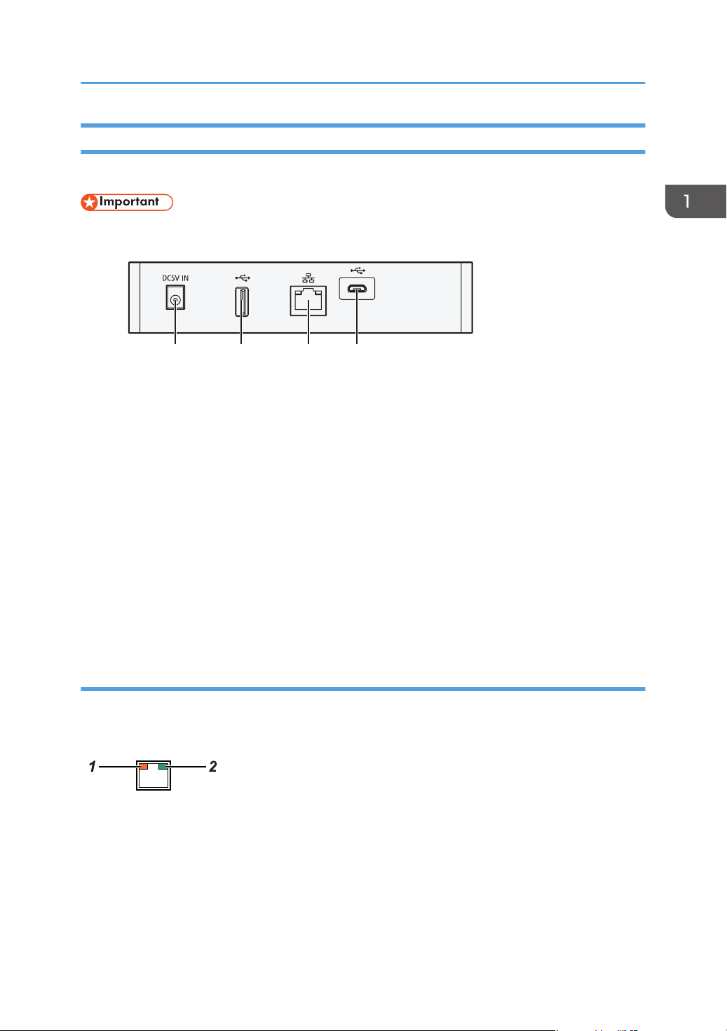
Back
This section explains names and functions of the parts on the back side of the RC Gate.
• Do not touch the outer screws (two outer screws shown) that are for customer engineers' operation.
1. Power Socket
This socket is used to connect the power cord.
2. USB 2.0 interface
You cannot use this port.
3. LAN Port
The network (Ethernet) interface port to connect the RC Gate to the network. This setting remains blank as it is
not specified when this product is shipped from the factory. Specify the IP address at the initial setting.
For details, see "5. The RC Gate Initial Settings", Setup Guide.
4. USB 2.0 interface (Maintenance port)
This is a port for connecting the micro-USB cable. This port is used when a customer engineer performs
maintenance, or when the designated administrator connects a PC to perform initial settings and registration of
the RC Gate.
LAN Port Indicator
You can check the connection condition of the LAN port.
1. Orange
Indicates that the RC Gate is connected to the network.
2. Green
Indicates that the RC Gate is transmitting data.
15
Page 18

1. About the RC Gate
About Options
This section explains the names and functions of options for the RC Gate.
Expandable storage is available as hardware options for the RC Gate. Contact your service
representative for installation.
• RICOH Remote Communication Gate A2 Storage 1000
The RC Gate can manage a maximum of 100 devices. If you have installed optional storage to
expand the capacity, up to 1,000 devices can be registered. For details, contact your service
representative.
16
Page 19
About the RC Gate Monitor
About the RC Gate Monitor
The RC Gate Monitor is the software used to register, monitor, and make settings of the RC Gate. The
software is pre-installed in the RC Gate.
Access the RC Gate Monitor in this equipment from web browser in the computer. The computer and this
equipment must be on the network.
• Some failure in operation or in displaying might occur in the following cases:
• You use web browsers lower than the recommended version.
• JavaScript is not set to valid.
• Cookie is not set to valid.
• You set to show cache in the web browser.
• Page layout may be out of shape depending on the font size settings. We recommend to set it to
"Medium" or smaller.
• Some letter deterioration may occur if you use languages that do not correspond to web browser.
• Specify settings so that the machine and main unit, and browser and main unit can be used in a
shared-usage mode.
• Depending on the browser being used, a dialog box asking whether you cancel the execution of
the script may appear. If this happens, select [No].
Applicable Operating System
Use operating systems which support the recommended web browsers below.
Recommended Web Browser
• Microsoft Internet Explorer 8.0 or later
• Mozilla Firefox 28.0 or later
• Check whether the certificate required for SSL encrypted communication has been installed on the
RC Gate.
Users of the RC Gate Monitor
The following type of users can log in to the RC Gate:
Administrator
The administrator can change the RC Gate settings, provide access permission to the customer
engineer.
17
Page 20
1. About the RC Gate
The administrator has all administrative (device administrator, user administrator, file administrator,
and network administrator) privileges of the subject device.
To Start the RC Gate Monitor
• Use a browser that can display disguised characters (such as asterisks) during password entry.
• Change the password. Be sure to change the password for actual operation of the RC Gate
Monitor.
• For security purpose, if you fail to log in to the RC Gate monitor at least 3 times in 5 minutes, you
will have to wait an additional 1 minute before you can try to log in again.
• After changing the password, be sure to remember it. If you forget it, you need to contact the
service representative to configure the machine's settings again.
• To use the machine in a CC-certified environment, check the version of the CC-certified firmware
matches that of the machine. For details about checking the version, see page 22 "Checking
Versions for CC Conformance".
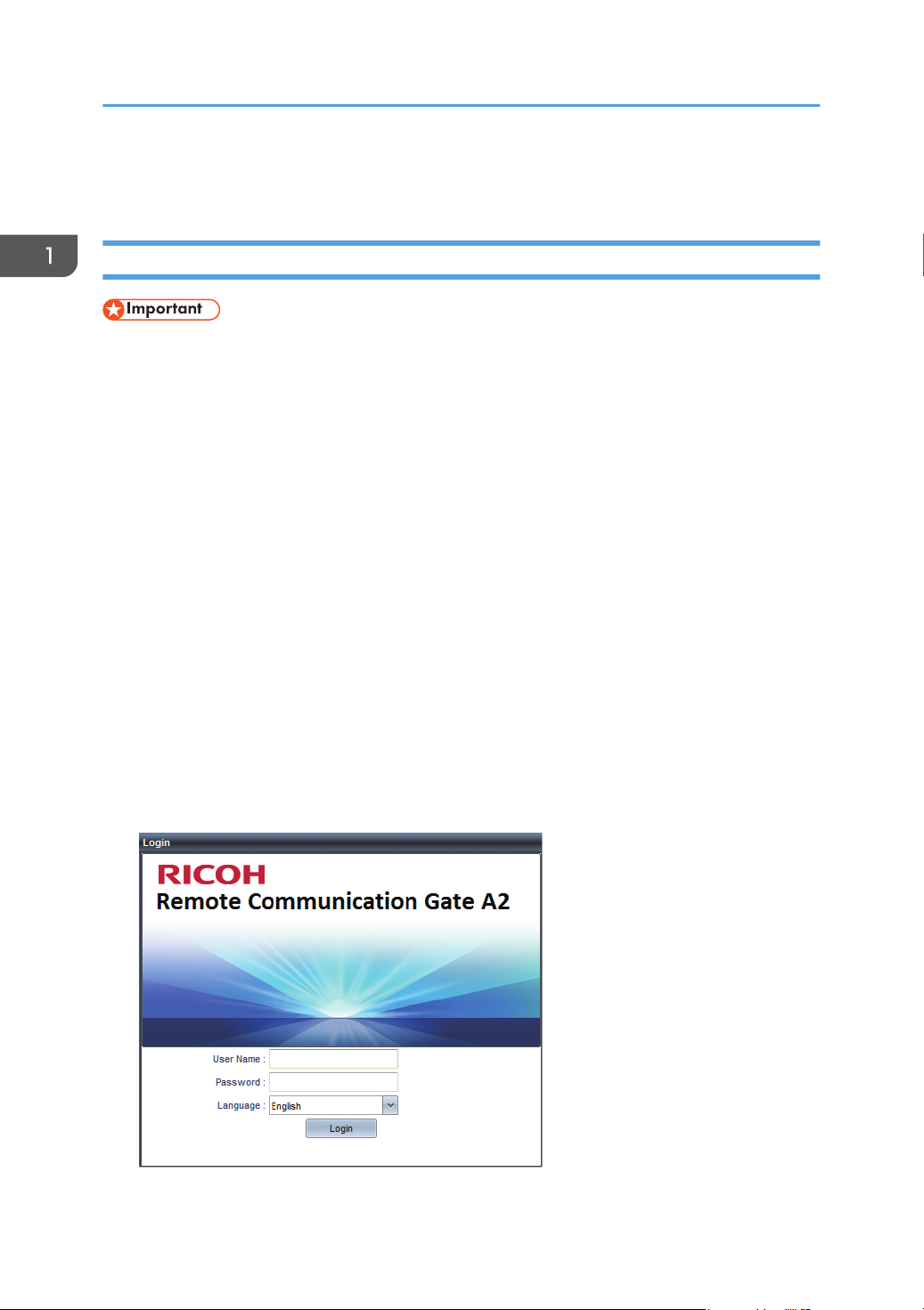
1. Start the web browser of the computer.
2. Enter "http://{LAN port IP address}:8080/index.html" in "Address".
3. Enter the user name "admin".
You cannot change the user name.
4. Enter the user password.
The default password is "administrator". Be sure to change the password for actual operation of the
RC Gate Monitor. For details, see page 28 "Setting a Password".
18
Page 21
About the RC Gate Monitor
5. Select the display language in [Language].
6. Click [Login].
• Security logs can be configured. For details, see page 79 "Security Log".
To Close the RC Gate Monitor
• User must always click [Logout] before closing the web browser.
• When you are finished using the RC Gate Monitor, remember to click [Logout]. If you leave the RC
Gate Monitor idle for 15 minutes, the screen locks. The idle time before locking the screen can be
changed.
1. Click [Logout] in the header area.
2. Confirm that you have logged out of the RC Gate Monitor, and then close the web
browser.
19
Page 22

1. About the RC Gate
20
Page 23
2. Setting up the RC Gate
This chapter explains the procedure for registering the RC Gate with the RS Center System.
Preparation for Use
To use the devices in a CC-certified environment, the administrator must perform the procedures
described in page 21 "Specifying the Device Settings" in advance. The administrator must read this
product’s manuals thoroughly before performing the procedures described in page 21 "Specifying
the Device Settings".
• To prevent this machine being stolen or willfully damaged, etc., install it in a secure location.
• If you connect the local-area network (LAN) to which the RC Gate is connected to an external
network, block unused ports between the LAN and the external network in accordance with your
operational environment by such means as a firewall.
• Upload the certificate by pressing the [Install Certificate] button in [Device SSL Setting] in [@Remote
Settings] in [@Remote].
• To prevent the customer engineer's account from being used illegally, select [Prohibit login with CE
account] in [Access Accounts] in [User Accounts] in [Security] in [System] except when a customer
engineer performs operations. When the customer engineer specifies this setting after his or her
performance is complete, make sure to confirm that the settings in the table described in page 21
"Specifying the Device Settings" match those of this machine, so that the CC-certified environment
can be maintained.
• To prevent the customer engineer from changing the security setting, when the customer engineer's
operation is complete, check if the settings described in page 21 "Specifying the Device Settings"
along with [Date/Time Settings], [Networking], and [IEEE 802.1x Authentication Setting] in
[Setup] in [System] are configured correctly. Likewise, check if [Proxy Server] in [Networking] in
[Server Settings] in [System] and [Connect to @Remote System] in [@Remote Settings] in [@Remote]
are configured correctly.
Specifying the Device Settings
This section explains how to specify the device settings to set up a CC-certified environment.
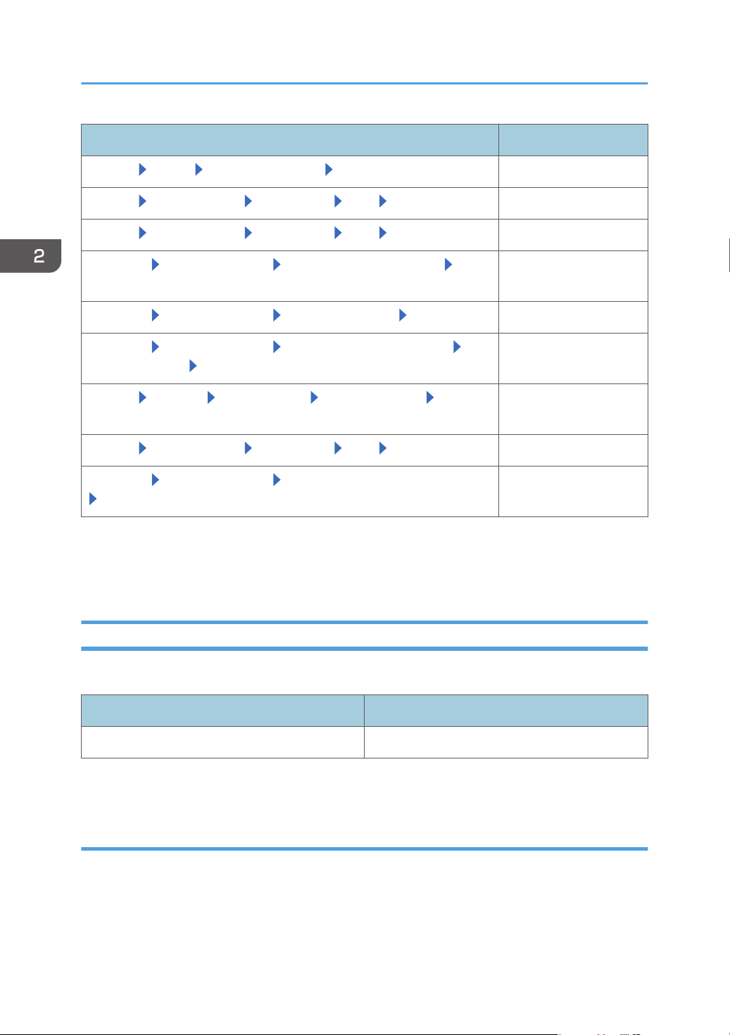
Item name Description
[System] [Setup] [Date/Time Settings] [Time zone] Current zone
[System] [Setup] [Date/Time Settings] [Date Settings] Current Date
21
Page 24
2. Setting up the RC Gate
Item name Description
[System] [Setup] [Date/Time Settings] [Time Settings] Current time
[System] [Server Settings] [Networking] [SSL] [Use SSL]
*1
[On]
[System] [Server Settings] [Networking] [SSL] [SSL 3.0] [Inactive]
[@Remote] [@Remote Settings] [Save Call/Counter History] [S/
MIME Setting]
*1
[@Remote] [@Remote Settings] [Device SSL Setting] [Use SSL]
[@Remote] [@Remote Settings] [Connect to @Remote System]
*1
[On]
[On]
2048bit
[Security Settings] [Device Encryption Level]
[System] [Security] [User Accounts] [Access Accounts] [Login
8 characters or more
password minimum length]
[System] [Server Settings] [Networking] [SSL] [Disable HTTP] Check the button
[@Remote] [@Remote Settings] [Permit @Remote Task Performance]
[Update System Firmware]
These settings can be specified at the initial setting.
*1
To update the RC Gate firmware, select [Permit]. If you update the system firmware, the system configuration
*2
will differ from the CC-certified one, so typically select [Do not permit].
*2
[Do not permit]
Checking Versions for CC Conformance
You can display the firmware version.
Classification Version
System 1.0.2
You can check the system version in [System Information and Settings] in [Server Settings] in [System].
Manuals
The reference numbers of the CC-certified manuals are as follows:
22
Page 25
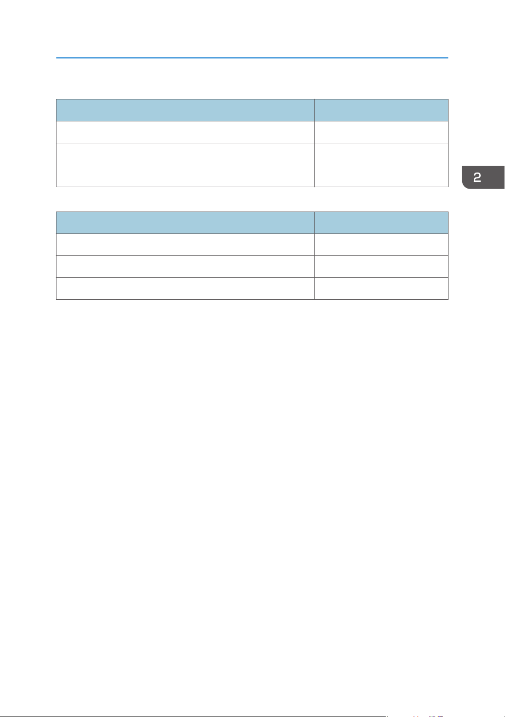
Mainly Europe
Manual Name Reference Number
Safety Information/Setup Guide D3AR-8600
Setup Guide D3AR-8620
Operating Instructions D3AR-8640E
Mainly North America
Manual Name Reference Number
Safety Information/Setup Guide D3AR-8610
Setup Guide D3AR-8620
Operating Instructions D3AR-8640E
Preparation for Use
23
Page 26
2. Setting up the RC Gate
Settings on Installation
Initial system settings appear when you first log in to the machine.
You can configure the following settings:
Date/Time Settings
Specify the time zone, date settings, and time settings.
For details, see page 67 "Date/Time Settings".
After configuration, click (Save).
Networking
Specify the networking.
For details, see page 68 "Networking".
After configuration, click (Save).
IEEE 802.1x Authentication Setting
Specify the IEEE 802.1x authentication settings.
For details, see page 70 "IEEE 802.1x Authentication Setting".
After configuration, click (Save).
• By clicking (Save) in the [IEEE 802.1x Authentication Setting] menu, you can specify [Proxy
Server Setting] and [Connect to @Remote System].
Proxy Server Setting
Specify the proxy server setting.
For details, see page 74 "Networking".
Connect to @Remote System
Specify the connection settings.
For details, see page 87 "Connect to @Remote System".
24
Page 27

Settings on Installation
• In [Connect to @Remote System], enter the request number. If you click [Register], the remaining
initial system settings appear.
Permit @Remote Task Performance
You can specify whether or not to authorize the following @Remote tasks.
• Device Registration
• Auto Discovery
• Device Status Information Notification
• Device Counter Information Notification
• Device Service Call
• Device Manual Call/ Customer Call
• Device Alarm Call
• Device Supply Call
• Device Information Change Notification
• Device Firmware Updating
• Update System Firmware
• Device Registration from @Remote Center System
• Information Setting Request from @Remote Center System
• Information Retrieval Request from @Remote Center System
For details, see page 91 "Permit @Remote Task Performance".
Auto Discovery
Specify the auto discovery.
For details, see page 94 "Auto Discovery".
After configuration, click (Save).
SNMP Access
Specify the SNMP access.
For details, see page 57 "SNMP".
After configuration, click (Save).
25
Page 28

2. Setting up the RC Gate
Add Device
Specify the add device.
For details, see page 51 "Add Device".
System Log
Change the log level and download the system log.
For details, see page 79 "System Log".
After configuration, click (Save).
Installation Completed
Installation can be finished by clicking [OK] button.
1. Click [OK] button.
26
Page 29
3. How to Configure and Check the
1
2
3
DJH011
Device
This chapter explains operations that can be done from each screen of the RC Gate Monitor.
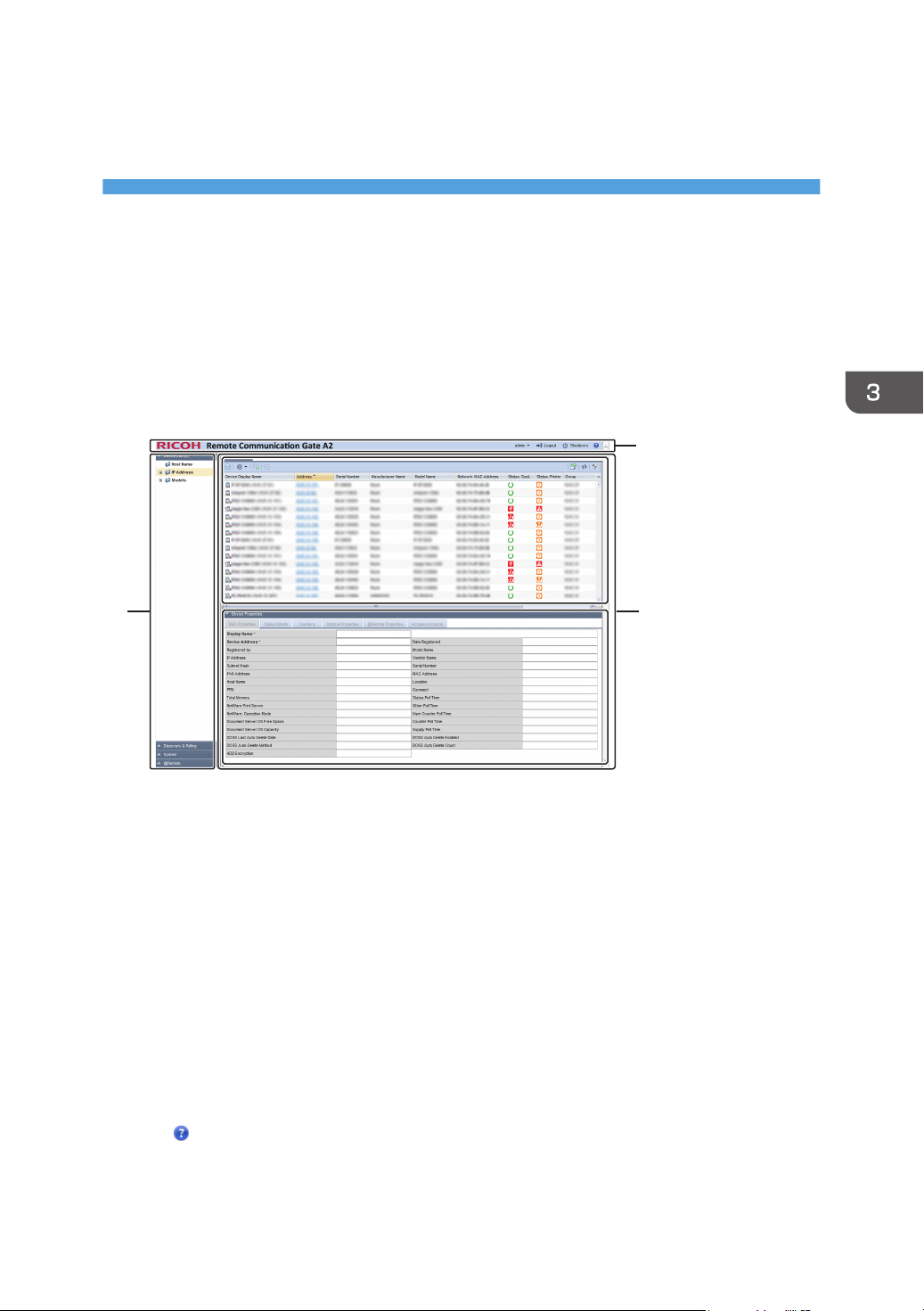
Screen Configuration
The standard screen configuration of the RC Gate Monitor is explained below using the Device List
section as examples.
1. Section area
Items in each section are displayed in this area.
When a section is clicked, details of each item are displayed in a tree structure.
2. Header area
• admin
You can change the RC Gate Monitor login password. For details about the password setting method,
see page 28 "Setting a Password".
• Logout
Log out the RC Gate Monitor. For details about log out, see page 19 "To Close the RC Gate Monitor".
• Shutdown
Shut down and put the RC Gate in standby mode. For details about shutdown, see page 29
"Shutdown the RC Gate".
•
Connect to the Ricoh website. You can also download "Setup Guide" and "Operating Instructions" from
the Ricoh website.
27
Page 30
3. How to Configure and Check the Device
3. Tab area
The upper part is the list area and the bottom part is the properties area.
The control screen that corresponds to the selected section tree item is displayed and uses the tabs to switch
between multiple control screens. To close multiple tabs at once, right-click on the tab and select [Close All but
Current] or [Close All].
• List area (The upper part)
A list of devices, tasks and other items are displayed above the tab area. Various icons are located on
the tool bar in the list area and can be used for the following operations:
• Import and export information such as the list information
See page 33 "Importing/Exporting the System Settings".
• Switch to an arbitrary view
See page 29 "Display Icons".
• Sort and classify lists
See page 31 "Sorting/Classifying Lists".
• You can access Web Image Monitor.
Click the IP address of the target device. The device management tool displayed may differ
depending on the target device.
• Properties area (The bottom part)
Detailed information about a device or task selected in the list area is displayed below the tab area and
used for editing and configuring the information. Click the name bar in the property area to open or
close the selected area. Drag the name bar to change the size (height) of the area.
Setting a Password
• Never use the default password. You can change the minimum number of characters used for the
password. (The default password contains 8 characters.) Specify a new password using up to 128
characters (ASCII character).
• You can use the following ASCII characters for password: (Space)"(double quotations)! % &'(/)
+,- . :$; <=>?[ ]^_`{|} ~0 1 2 3 4 5 6 7 8 9 #a b c d e f g h i j k l m n o p q r s t u v w x y z @ A
B C D E F G H I J K L M N O P Q R S T U VW X Y Z *
• If the error message "Failed to change the entry information." appears, check that the current
password is entered correctly, the password uses supported characters only, or the number of
characters does not surpass the limit, and then retry the entry.
• Change the passwords at intervals of 6 months or less.
• Avoid using well known words or phrases, or repeated characters that can easily be guessed.
• Do not leave passwords written where they can be seen.
• New passwords become valid at next login.
28
Page 31
Screen Configuration
• After changing the password, be sure to remember it. If you forget it, you need to contact the
service representative to configure the machine's settings again.
1. In the header area, click [admin] and [Change Password].
2. In the [Password], enter a password.
3. In the [New Password], enter a new password.
4. In [New Password (Confirm)], enter the new password again to prevent mistyping.
5. Click [OK].
Shutdown the RC Gate
• If the power plug is disconnected before shutting down the RC Gate Monitor, the storage will be
damaged. In such a case, the latest logs will be lost. Before disconnecting the power plug, be sure
to shut down the machine to switch to the standby mode.
1. In the header area, Click [Shutdown].
2. When the confirmation message appears, click [Yes].
• You can also switch to the standby mode by pressing the Power button.
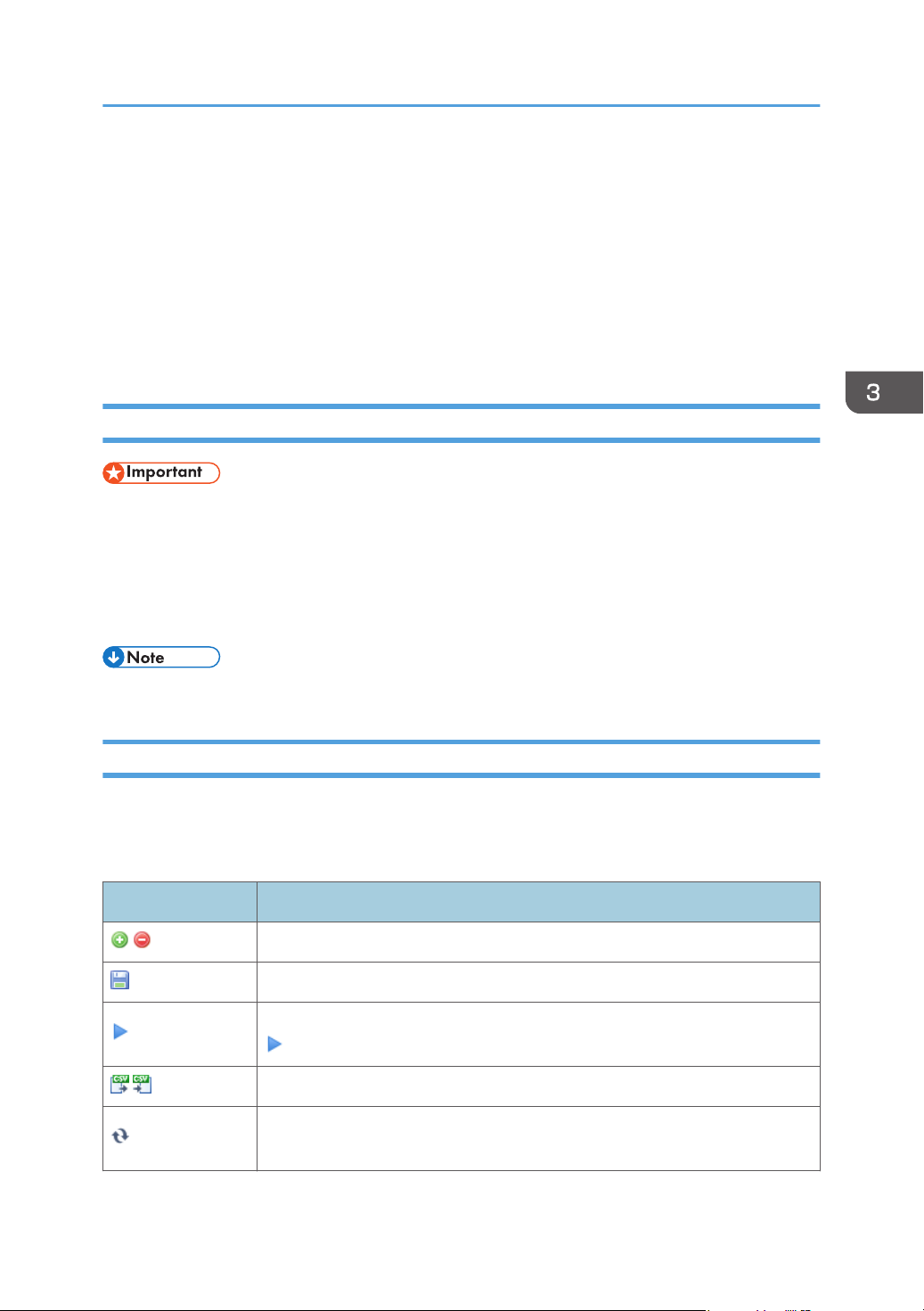
Display Icons
All of the operation icons and device icons displayed by the RC Gate Monitor are described below.
There are some operation icons that are not displayed depending on the function.
Operation icons
Icon Description
Add or delete devices and tasks to/from the list.
Save the edited device information, configured task and templates.
To immediately execute the detected result by the discovery function, click the
(Immediately perform) icon.
Export or import the list information in a CSV file.
Update the list information. The information temporarily retrieved by the RC
Gate is retrieved again.
29
Page 32
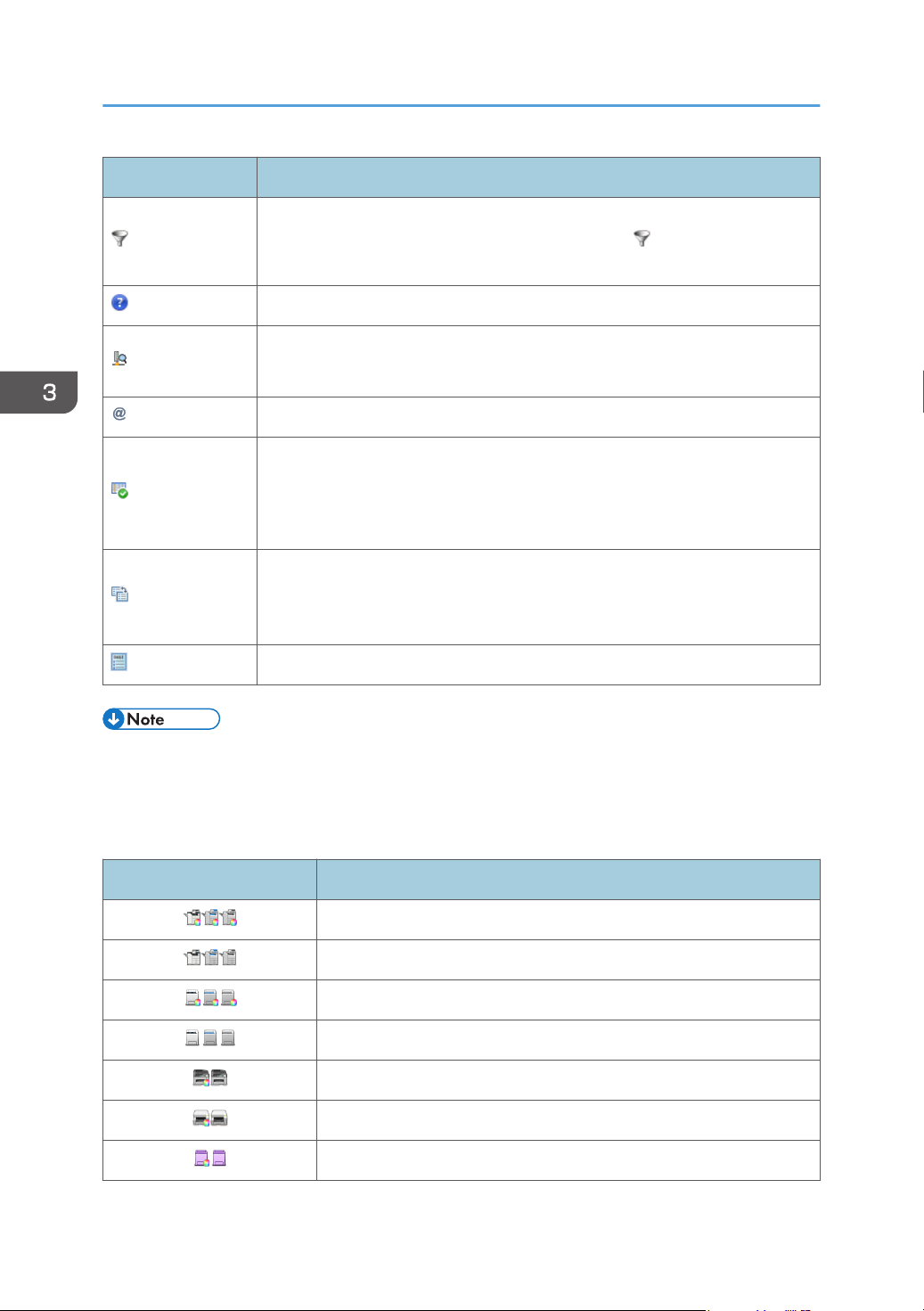
3. How to Configure and Check the Device
Icon Description
Filter the list information. Click to display an input/selection area over the item
name in the list. Enter or select a search key and click (Filters) located to the
right of the input area or press the Enter key. The relevant entry is displayed.
Connect to the Ricoh website.
Retrieve device data from the router.
For details, see page 62 "Search the Device".
Display the debug log, register devices, and change the encryption key length.
Check whether the counter information can be acquired and processed on a
per-user basis for devices specified by the RS Center System. This can be
executed by clicking icon. The dialog box reporting the result (success or
failure) appears.
Change the access profile of the device selected from the device list.
For details about specifying the access profile, see page 61 "Specifying
Access Profiles".
You can execute polling manually.
• For details about the information that can be exported by the CSV file and the CSV file name, see
page 33 "Importing/Exporting the System Settings".
• For the format of CSV files, see page 35 "Format of CSV Files".
Device icons
Icon Description
RICOH digital full color multifunctional machine
RICOH digital monochrome multifunctional machine
RICOH color laser printer
RICOH monochrome laser printer
*
*
*
*
RICOH hybrid multifunctional machine
RICOH gel jet printer
RICOH OEM color/monochrome multifunctional machine or printer
30
Page 33
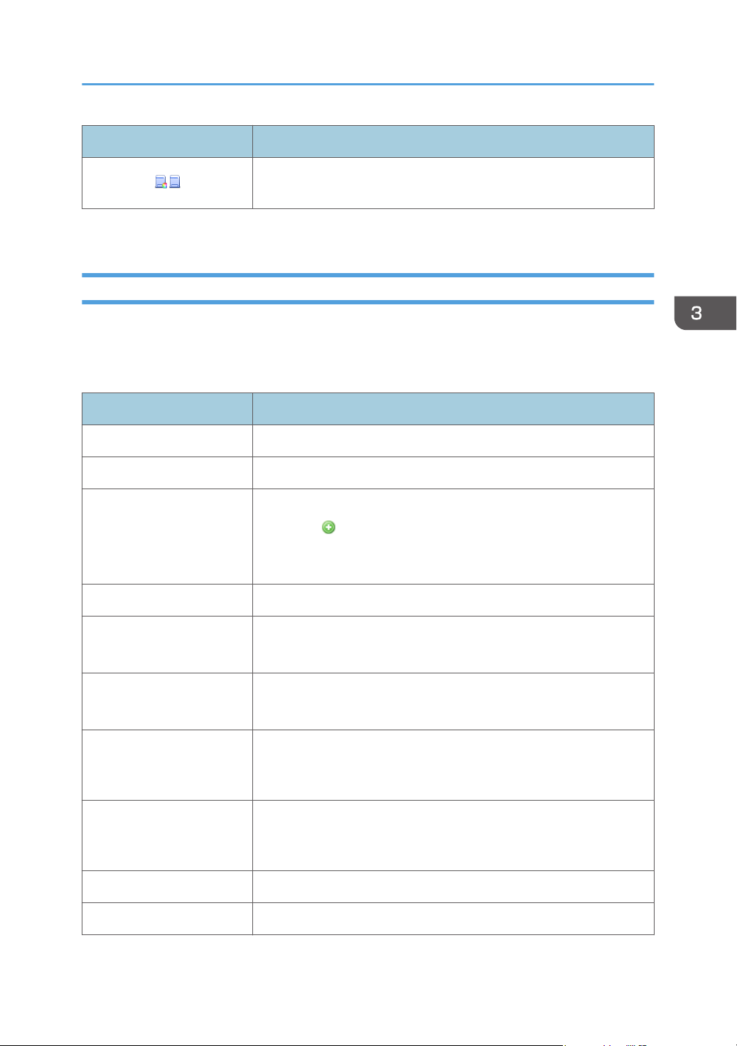
Screen Configuration
Icon Description
Non-RICOH brand color/monochrome multifunctional machine or
printer
*
Device icons to be displayed differ depending on the machine being used.
Sorting/Classifying Lists
This section describes how to sort and classify lists for ease of view.
Place the cursor on the item name of a row and right-click. The following menu items for sorting and
classification are displayed. Some menu items are not displayed depending on the function.
Menu item Description
Ascending Sort Sort the target row in the ascending order.
Descending Sort Sort the target row in the descending order.
Configure Sort Click this to display a sort dialog.
By clicking (Add), you can select items from [Columns] and sort
them by specifying the sort order. After the setting is complete, click
[Apply].
Clear Sort Clear the sorting status.
Auto Fit All Columns Display all columns with widths automatically adjusted.
Items in all columns are displayed fully.
Auto Fit Adjust the target column width.
Specified columns are displayed at fully.
Columns Set the items to be displayed in or to be hidden from the list. In the item
name list on the submenu, select check boxes for the items to be
displayed and clear the check boxes for the items to be hidden.
Freeze "Item name" The rows on the left including the target rows are fixed so that they are
not hidden even when horizontal scrolling is performed. The item name
is displayed as "Item name".
Unfreeze "Item name" Unfreeze the target rows. The item name is displayed as "Item name".
Right Align The target row information is right-justified.
31
Page 34
3. How to Configure and Check the Device
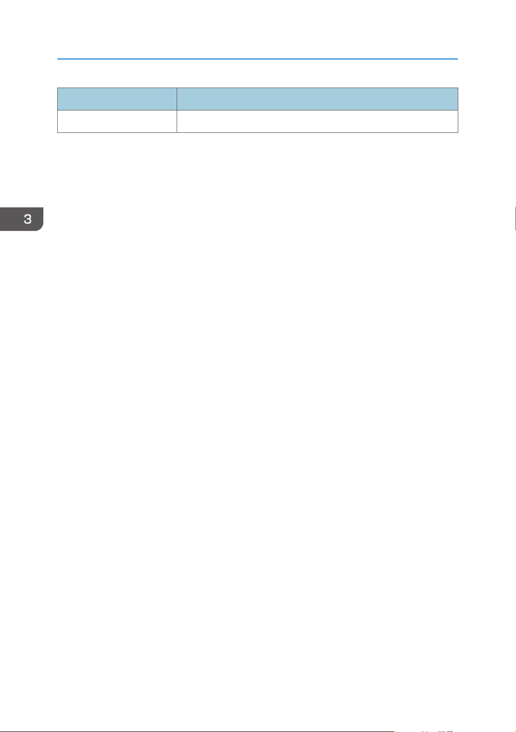
Menu item Description
Left Align The target row information is left-justified.
32
Page 35
Importing/Exporting the System Settings
Importing/Exporting the System Settings
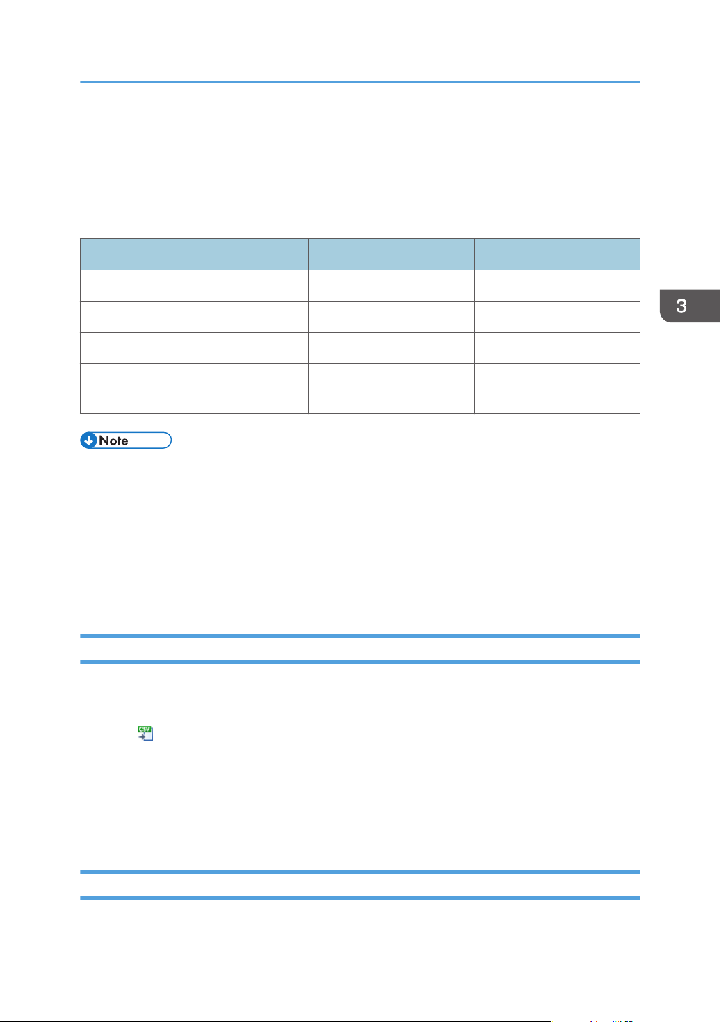
Importing CSV files to the RC Gate enables you to integrate register volume information such as devices
and user data.
Information that can be imported/exported as a CSV file
Information type Import Export
Device List Not available Available
Discovery Range Available Available
Security Log Not available Available
Shift Device Firmware Update
Prohibited Period
• The creation date, the exported function name will be automatically appended to the exported
CSV file name. Specify the date and time format of the creation date in [Date Display Format]. For
details about the date and time format, see page 67 "System Settings".
• When editing the CSV file to be imported, follow the formatting rule, and edit the file accordingly.
For details about the format of CSV files, see page 35 "Format of CSV Files".
• For details about importing the CSV file, see page 33 "Importing a CSV File".
• For details about exporting the CSV file, see page 33 "Exporting a CSV File".
Available Not available
Importing a CSV File
You can import a discovery range and a shift device firmware update prohibited period data as CSV
files.
1. Click (Imports data from CSV files.).
2. Click [Browse…].
3. Select the CSV file to import, and then click [Open].
4. Click [Upload].
5. Click [OK].
Exporting a CSV File
You can save a device list, a discovery range, and a security log as CSV files.
33
Page 36
3. How to Configure and Check the Device
1. Click (Export data to a CSV file).
2. Specify a save destination and a file name, and then click [Save].
34
Page 37
# Format Version: 6.1.1.X
# Generated at: XX/XX/XXXX XX:XX:XX
# Function Name: Broadcast Discovery Range
Subnet
X.X.X.X
Subnet Mask
X.X.X.X
Range Name
XXXX
Description
XXXX
DJG150
Format of CSV Files
Format of CSV Files
CSV files are used for import/export of the RC Gate.
Devices can be exported to a CSV file ( ), and the data from the CSV file can be loaded to a CSV file
after editing it ( ).
This procedure is explained using the CSV file for broadcasting the discovery range.
The variables are indicated by "X".
Typical description of a CSV file
Items in the CSV file appear in the following format.
• UTF-8 is used as the character code for CSV files. However, GB18030 is used as the character
code when the language is Chinese.
• When data includes commas (,) or double quotations ("), enclose the entire data with double
quotations. When enclosing with double quotation marks data with a double quotation marks,
place additional quotation marks outside the double quotation marks in the data. (e.g., a, "b", c =>
"a, ""b"", c")
Format of a Device List CSV File
A device information CSV file is written out in the format indicated below:
The variables are indicated in bold letters.
Line
number
1 # Format Version: 6.1.1.X
2 # Generated at: (Date/time of write-out)
3 # Function Name: Device List
4 "(Item name of the column)"
Contents
35
Page 38
3. How to Configure and Check the Device
Line
number
5 "(Value of the device that corresponds to the item name of the column)"
As "Item name of the column" in line 4, the item name of the column displayed in the header of the
device list is written out row-by-row sequentially from the left-hand side.
In Line 5 and subsequent lines, the values of all devices displayed in the device list at the time of export
can be written line-by-line along with the values in the columns not displayed on the machine’s control
panel.
Contents
Format of a Discovery Range CSV File
CSV files are divided into two types depending on the search method of discovery range.
Broadcast
The broadcast CSV file can be read and written in the following settings:
• [Broadcast] in [Add Device] in [Discovery & Polling].
• [Broadcast] in [Auto Discovery] in [@Remote Settings] in [@Remote].
The variables are indicated in bold letters.
Line
number
1 # Format Version: 6.1.1.X
2 # Generated at: (Date/time of write-out)
3 # Function Name: Broadcast Discovery Range
4 "(Row name)"
5 "(Value that corresponds to row name)"
The "Row name" and row number in line four, and their corresponding values of line five and
subsequent lines are as follows:
Row
number
A Subnet Enter a subnet address. An IPv4 address can be used.
Row name Value of line five and subsequent lines
Contents
36
Page 39
Format of CSV Files
Row
number
Row name Value of line five and subsequent lines
B Subnet Mask Enter a subnet mask.
C Range Name
D Description
Enter a discovery range name. Use up to 61 alphanumeric
characters.
Enter a discovery range description. Use up to 61
alphanumeric characters.
Rows C and D appear only you write data using the broadcast setting in [Auto Discovery] in [@Remote
Settings]. However, you can also have CSV files including rows C and D read into the broadcast setting
in [Add Device]. Also, you can have CSV files written from the broadcast setting in [Add Device] read
using broadcast setting in [Auto Discovery].
• Do not change the information in lines one through three, as this information is used for
identification.
Network Search
The network search CSV file can be read and written in the following settings.
• [Network Search] in [Add Device] in [Discovery & Polling].
• [Manual Discovery] in [Discovery & Polling].
• [Network Search] in [Auto Discovery] in [@Remote Settings] in [@Remote].
The variables are indicated in bold letters.
Line
number
Contents
1 # Format Version: 6.1.1.X
2 # Generated at: (Date/time of write-out)
3 # Function Name: Network Search Discovery Range
4 "(Row name)"
5 "(Value that corresponds to row name)"
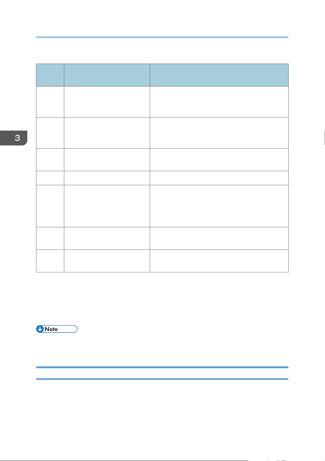
The "Row name" and row number in line four, and their corresponding values of line five and
subsequent lines are as follows:
37
Page 40
3. How to Configure and Check the Device
Row names and their corresponding values
Row
number
A Range Type
B IP Start/IP Address/Host Name
C IP End
D Subnet Mask Enter a subnet mask.
E 0=Include/1=Exclude
F Range Name
Row name Value of line five and subsequent lines
Specify the search criteria from "One Host Name",
"One IP Address", "Specify IP Range", and "IPv6
Address".
Enter the discovery target host name, IP address, IPv6
address or start IP address of the discovery target IP
address range.
Enter an end IP address of the discovery target IP
address range.
Specify whether to include or exclude network search
as a search range.
The data is included in the network search if you enter
"0" and excluded if you enter "1".
Enter a discovery range name. Use up to 61
alphanumeric characters.
G Description
Rows F and G appear only when writing data using the broadcast setting in [Auto Discovery] in
[@Remote Settings]. Nonetheless, you can also have CSV files including Rows F and G read into the
broadcast setting in [Add Device] or [Network Search] in [Manual Discovery]. Also, you can have CSV
files written from the broadcast setting in [Add Device] or [Network Search] in [Manual Discovery] read
using broadcast setting in [Auto Discovery].
• Do not change the information in lines one through three, as this information is used for
identification.
Enter a discovery range description. Use 0 to 61
alphanumeric characters.
Format of a Security Log CSV File
Security log CSV file is written out in the format indicated below:
The variables are indicated in bold letters.
38
Page 41
Format of CSV Files
Line
number
1 # Format Version: 6.1.1.X
2 # Generated at: (Date/time of write-out)
3 # Function Name: Security Log
4 "(Row name)"
5 "(Value that corresponds to row name)"
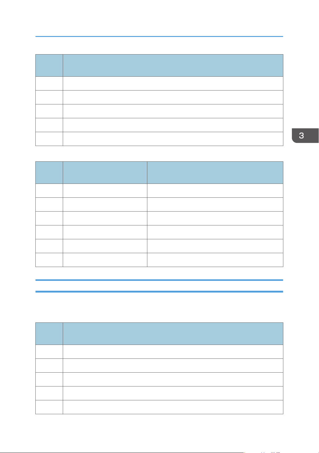
Row names and their corresponding values
Row
number
A Date Indicates a date the log data was recorded.
B Role Indicates a type of user who accessed the RC Gate.
C User Name Indicates a user name.
D Action Indicates the log's generating factor.
Row name Value of line five and subsequent lines
Contents
E Security Log Details Indicates a detail of the security log.
F Result Indicates a result.
Format of a Shift Device Firmware Update Prohibited Period CSV File
The shift device firmware update prohibited period CSV file is written out in the format indicated below:
The variables are indicated in bold letters.
Line
number
1 # Format Version: 6.1.1.X
2 # Generated at: (Specified time)
3 # Function Name: Shift Device Firmware Update Prohibited Period
4 "(Row name)"
5 "(Value that corresponds to row name)"
Contents
39
Page 42
3. How to Configure and Check the Device
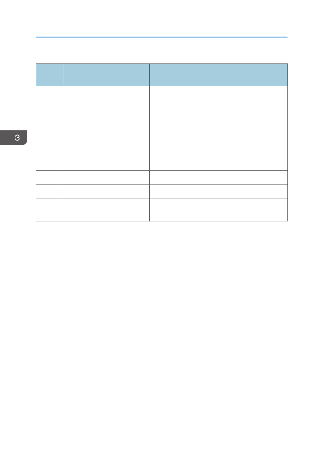
Row names and their corresponding values
Row
number
Row name Value of line five and subsequent lines
Specify the search criteria from "One Host Name",
A Range Type
"One IP Address", "Specify IP Range", and "IPv6
Address".
Enter the discovery target host name, IP address, IPv6
B IP Start/IP Address/Host Name
address or start IP address of the discovery target IP
address range.
C IP End
Enter the end IP address of the shift setting target IP
address range.
D Subnet Mask Enter a subnet mask address range.
E Shift Time [H] Specify a figure between -12 and 12.
F Description
Enter the description of each item in the shift setting.
Use 0 to 61 characters.
40
Page 43
4. Device List
This chapter explains the items included in the Device list.
Device List Items
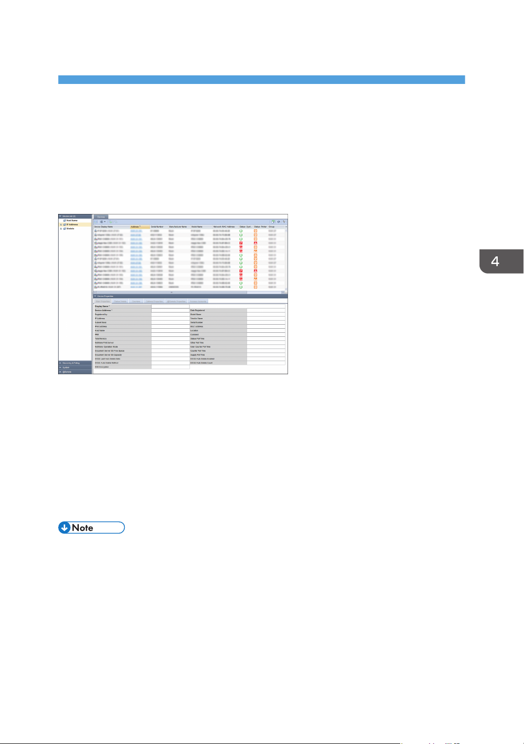
The devices that this product manages appear in the [Device List] section. To display the settings screen,
click [Device List].
Retrieved devices are automatically classified according to the following three list items:
Host Name
A tree view is used to display host names that are separated by domain hierarchies. Whether an
actual domain or not, domain hierarchies are separated by dots.
IP Address
A tree view is used to display IPv4 addresses that are separated every 8 bits.
Models
Names of device manufacturers or models are used for classification.
• The device list applies only to models registered in the RS center System. For details about adding a
device to the device list and registering a device to the RS Center System, see page 62
"Searching for Devices".
41
Page 44
4. Device List
Checking Device Properties
Device properties that are retrieved by the RC Gate are explained below.
When a device is selected in the device list, the information about the device retrieved by discovery or
polling is displayed in the properties area.
• Some items are not displayed depending on the device.
Displaying Device Properties
1. In the [Device List] section, click a target group to display the corresponding device list.
2. Select a target device in the list area.
3. The information about the selected device is displayed in the [Device Properties].
Check the device information and statuses by switching the following tabs:
• Main Properties
• Status Details
• Counters
• Optional Properties
• @Remote Properties
• Access Accounts
Main Properties
You can check general information such as display name, model name, and IP address, along with date
registered, serial number and MAC address.
• Display Name
The name of the device is displayed. You can change the display name to the one you want.
• Device Address
The address for the RC Gate to access the device is displayed.
• Date Registered
The registration date is displayed. This date/time indicates when discovery or a device is manually
added.
• Registered by
42
This is displayed as "localhost".
Page 45
• Model Name
• IP Address
• Vendor Name
• Subnet Mask
• Serial Number
• IPv6 Address
• MAC Address
• Host Name
• Location
• PPM
• Comment
• Total Memory
• Status Poll Time
• NetWare Print Server
• Other Poll Time
Checking Device Properties
• NetWare: Operation Mode
• User Counter Poll Time
• Document Server DS Free Space
• Document Server DS Capacity
• Counter Poll Time
• Supply Poll Time
• DOSS Last Auto Delete Date
• DOSS Auto Delete Enabled
• DOSS Auto Delete Method
• DOSS Auto Delete Count
• HDD Encryption
• On a RICOH MFP or printer, the settings configured in Web Image Monitor are displayed as
"WIM Location" and "WIM Comment" information.
Status Details
You can check the device status by switching the [Printer Status], [Paper Tray], [Toner/Ink], and [Output
Tray] tabs.
43
Page 46
4. Device List
Printer Status
• System
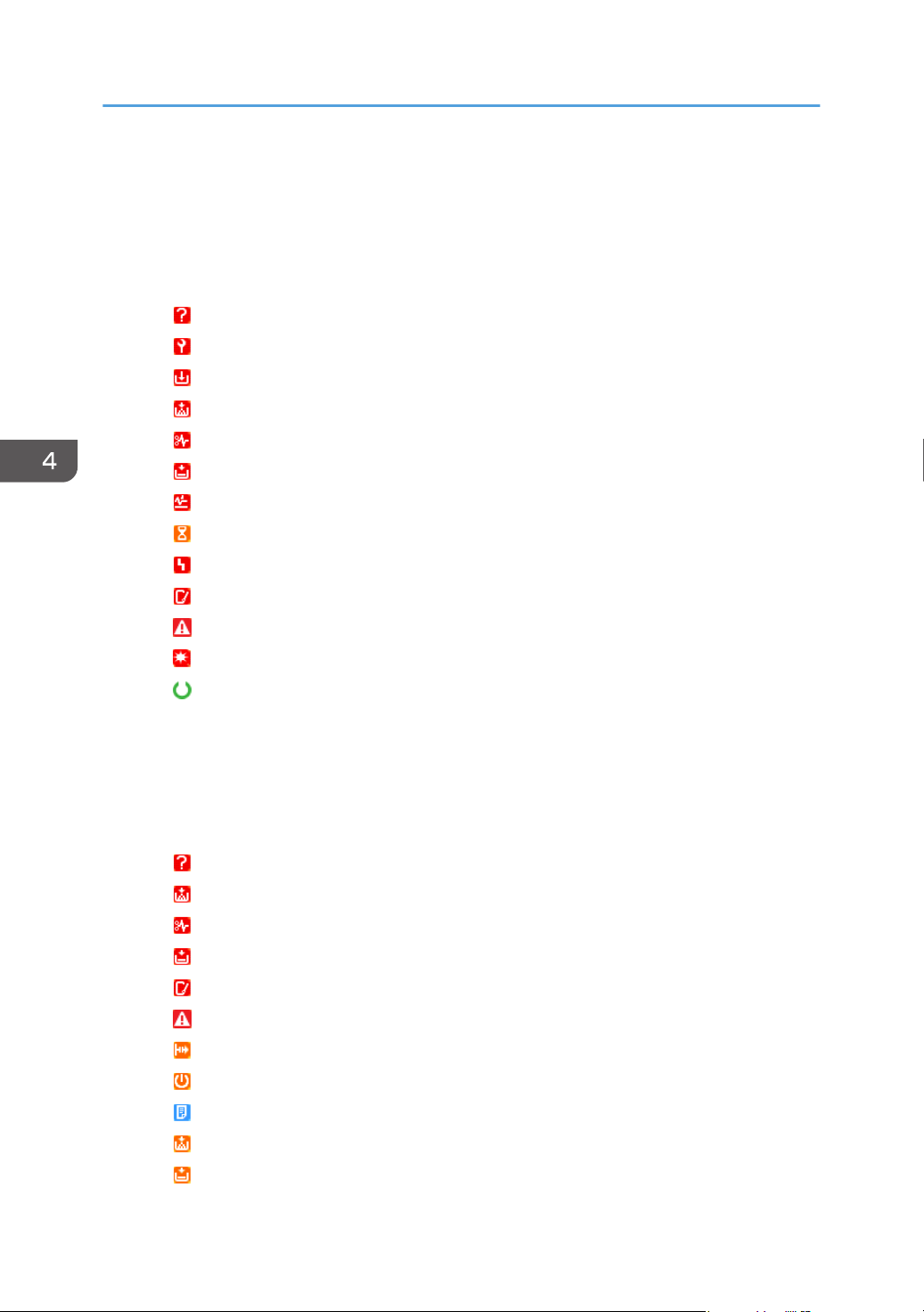
You can check the system status. To display detailed information, place the mouse cursor on
the status icon. If there are multiple statuses, the status of the higher priority is displayed.
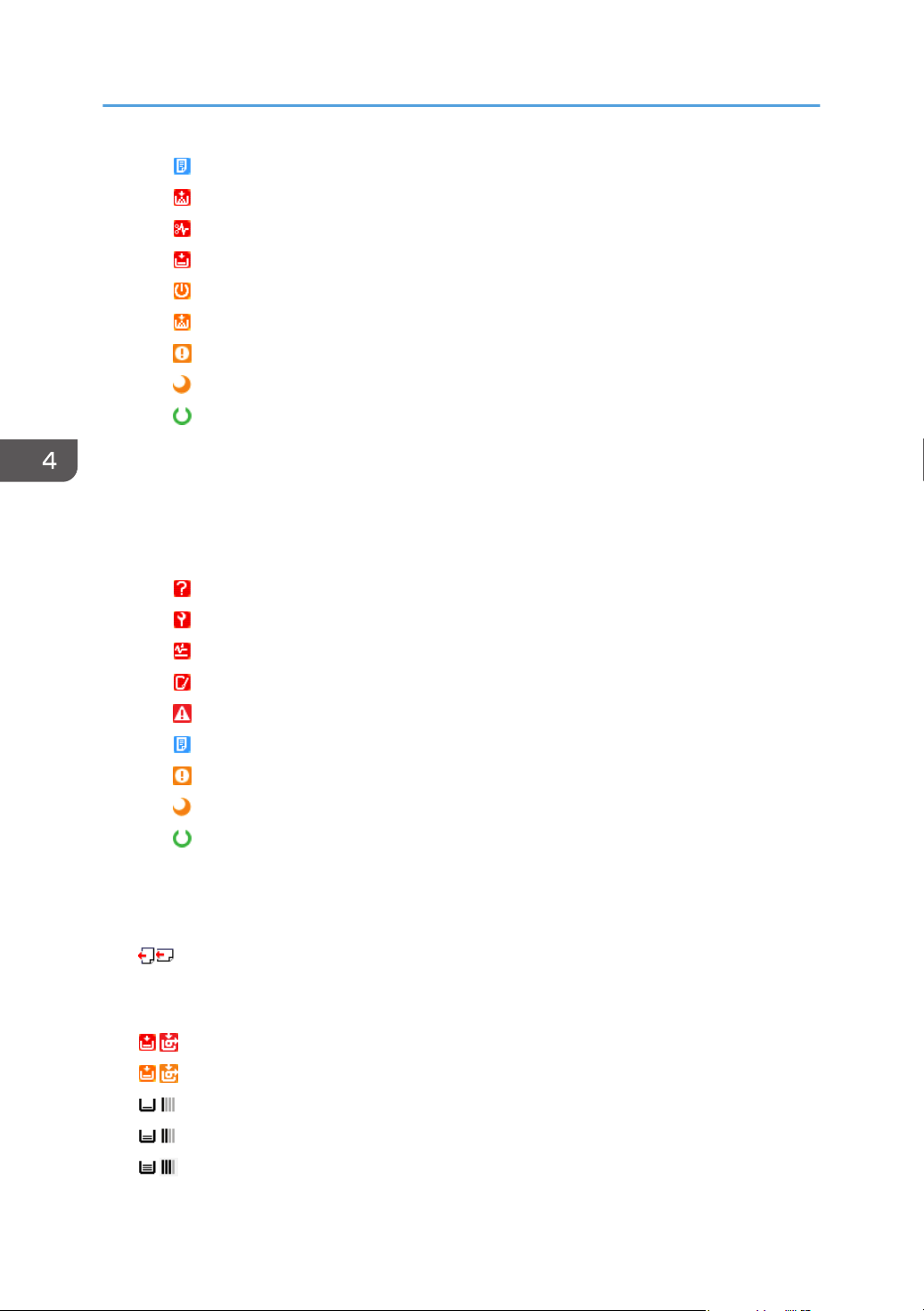
Descriptions of the icons indicated below are displayed in the order of highest priority.
: No response
: Service call
: Replace/supply
: Toner/ink exhausted
: Paper jam
: No paper
: Paper jam in ADF
: Performing maintenance
: Fax transmission error
: Open cover
: Miscellaneous error
: Access violation has been detected
: Ready
• Printer
You can check the statuses of the printer functions. To display detailed information, place the
mouse cursor on the status icon. If there are multiple statuses, the status of the higher priority is
displayed.
Descriptions of the icons indicated below are displayed in the order of highest priority.
: No response
: Toner/ink exhausted
: Paper jam
: No paper
: Open cover
: Miscellaneous error
: Offline
: Warming up
: Busy
: Toner/ink cartridge almost empty
44
: Paper almost empty
Page 47
Checking Device Properties
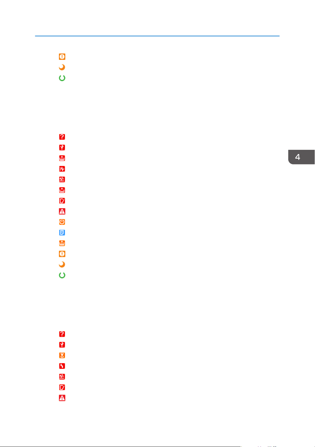
: Caution
: Energy saver mode
: Ready
• Copier
You can check the statuses of the copier functions. To display detailed information, place the
mouse cursor on the status icon. If there are multiple statuses, the status of the higher priority is
displayed.
Descriptions of the icons indicated below are displayed in the order of highest priority.
: No response
: Service call
: Toner/ink exhausted
: Paper jam
: Paper jam in ADF
: No paper
: Open cover
: Miscellaneous error
: Warming up
: Busy
: Toner/ink cartridge almost empty
: Caution
: Energy saver mode
: Ready
• Fax
You can check the statuses of the fax functions. To display detailed information, place the
mouse cursor on the status icon. If there are multiple statuses, the status of the higher priority is
displayed.
Descriptions of the icons indicated below are displayed in the order of highest priority.
: No response
: Service call
: Performing maintenance
: Fax transmission error
: Paper jam in ADF
: Open cover
: Miscellaneous error
45
Page 48
4. Device List
• Scanner
: Busy
: Toner/ink exhausted
: Paper jam
: No paper
: Warming up
: Toner/ink cartridge almost empty
: Caution
: Energy saver mode
: Ready
You can check the statuses of the scanner functions. To display detailed information, place the
mouse cursor on the status icon. If there are multiple statuses, the status of the higher priority is
displayed.
Descriptions of the icons indicated below are displayed in the order of highest priority.
: No response
: Service call
: Paper jam in ADF
: Open cover
: Miscellaneous error
: Busy
: Caution
: Energy saver mode
: Ready
Paper Tray
You can check the paper tray type. Also, you can check the orientation, size, type and remaining
quantity of paper loaded in each paper tray.
: Indicates two orientations of the loaded paper
On devices using rolled paper, the icon on the right-hand side that indicates the remaining paper
amount is displayed.
: No paper
: 0-20%
: 20-40%
: 40-60%
46
: 60-80%
Page 49
Checking Device Properties
: 80-100%
Toner/Ink
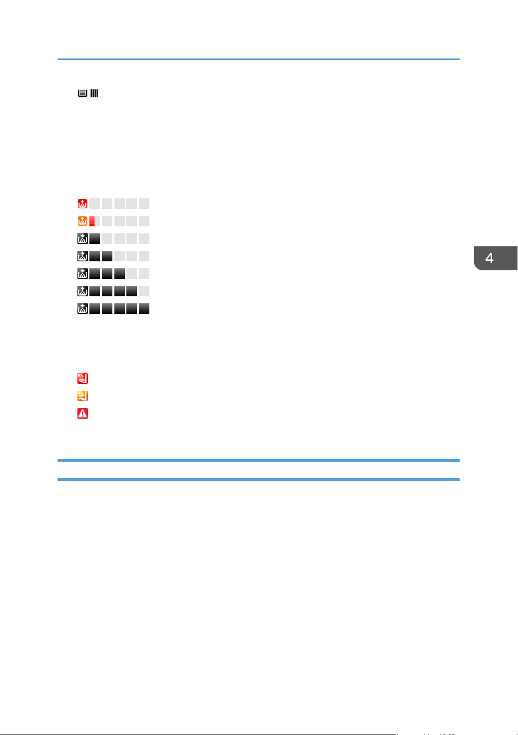
You can check the colors of toner/ink and the remaining quantity of each toner/ink. "Unknown"
may be displayed for some devices or monochrome MFPs if the remaining quantity of toner or ink
cannot be detected.
The level of remaining toner or ink is indicated as shown below. The color of the indicator is the
same as that of the applicable toner. Black is used as an example below:
: Toner/ink is empty
: Toner/ink cartridge is almost empty
: 0-20%
: 20-40%
: 40-60%
: 60-80%
: 80-100%
Output Tray
You can check the output tray type and the status of each tray.
The output tray status is indicated by the icons as shown below:
: Output tray is full
: Paper is located in output tray
: Miscellaneous error
(Nothing appears): Normal status
Counters
You can check counter information such as the number of pages printed in color/monochrome or
transmitted pages.
• Total
A total of the counters for the copier, printer, and fax functions
• Copy Color: Black, Full, Twin, Mono
Counter for the copier function
• Printer Color: Black, Full, Twin, Mono
Counter for the printer function
• Economy Color Counter
• Fax Color: Full, Mono
47
Page 50
4. Device List
Counter for the fax function
• A3/DLT
• A2
• Duplex
• Send: Color, Mono
A total of the counters for the scanner transmission and fax transmission functions
• Fax Send
• Scanner Send: Color, Mono
The counter for the scanner transmission function
• Total: Mono, Color
• Coverage Color: Pages, Percentage
• Coverage B&W: Pages, Percentage
• Color 1, 2, 3
• Active
• Idle
• Preheat
• Sleep
• OffMode
Optional Properties
You can check the individual information of optional properties by switching the [Custom Properties],
[Installed Applications], [Firmware and Platform], and [Functions] tabs.
Custom Properties
Users can configure custom properties. For details about configuring custom properties, see
page 49 "Setting custom properties".
Installed Application
You can check Application, Version, and Product ID.
Firmware and Platform
The user can check each device version.
Functions
You can check the functions and printer language provided for the device.
• Functions
48
Page 51

Checking Device Properties
You can check the functions provided for the device, such as manual paper feed, duplex
printing, and card printing functions.
• Printer Language
You can check the printer language provided for the device.
Setting custom properties
Custom properties are used for adding arbitrary information to devices. Information such as
administration number and asset number can be set for each device.
1. In the section area, click [System].
2. In the [Server Settings] category on the section tree, click [Display].
3. Enter the item name to be used for custom properties.
You can specify the name of each item using up to 255 alphanumeric characters and create up to
10 custom properties.
However, you cannot create multiple custom properties of the same name.
4. Click (Save).
5. Select a target device from the device list.
6. In the properties area, click the [Optional Properties] tab, and then click [Custom
Properties] tab.
7. Double-click the [Value] row, and enter the unique information.
Use 1 to 255 characters.
8. Click (Save) when the setting is configured.
@Remote Properties
Part of the device information the RS Center System manages appears.
• Machine Id
• Connection Type
• Cutoff Date
• Service Depot
• Service Depot Phone No
• Supply Order From
• Supply Order Phone No
• Encryption Length
49
Page 52
4. Device List
Access Accounts
You can check access account profiles used for access to devices. You can also choose whether or not
to display the access profile used for communication with devices and change the access profile. In
addition, you can change device administrators. For details about specifying the access profile, see
page 61 "Specifying Access Profiles".
For the functional outlines or operations of access accounts, see page 59 "Configuring Access
Accounts".
Manually Performing Polling
1. Select a target device in the device list.
2. Click in the list area, click [Request Polling].
3. Specify the types of polling to perform, and click [OK].
50
Page 53
5. Discovery and Polling
This chapter enables you to configure settings to access devices using the discovery and polling
functions.
Discovery and Polling
Add Device
Add any device you want to use.
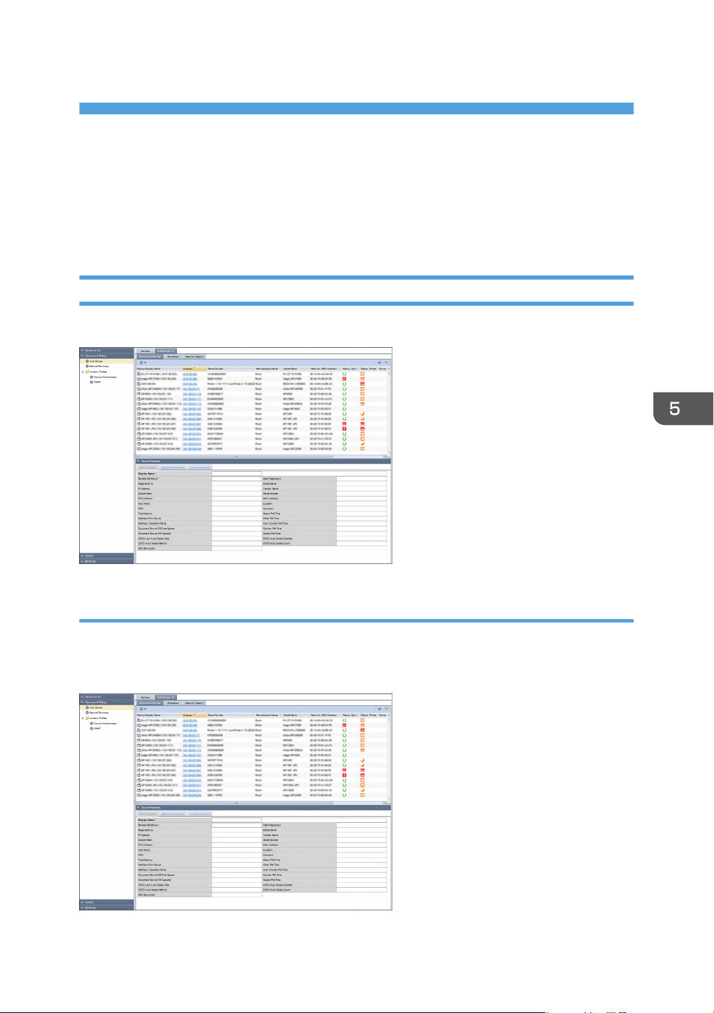
[Discovered Devices] tab
The devices searched, detected, and added from the [Broadcast] and [Network Search] tabs appear in
this window. To display the settings screen, click [Discovery & Polling] - [Add Device] and [Discovered
Devices].
51
Page 54
5. Discovery and Polling
Item name Description
List area Indicates the added device as a list.
Properties area Indicates the [Main Properties], [@Remote Properties], and
[Access Accounts].
For details the Device Properties, see page 42 "Checking Device
Properties".
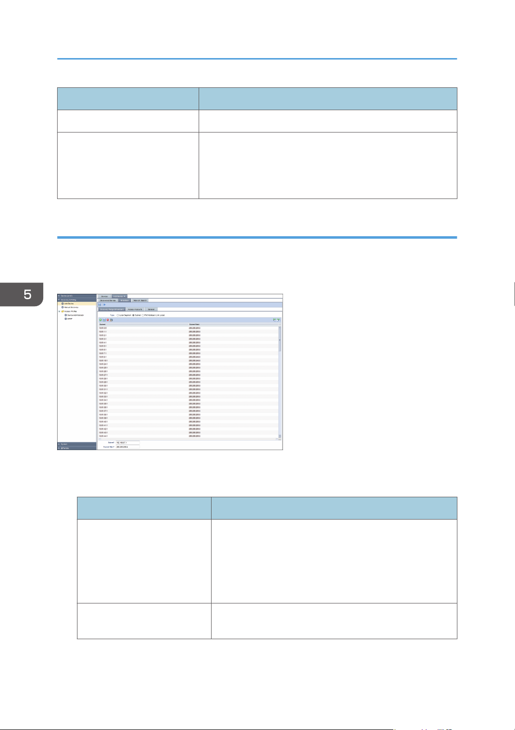
[Broadcast] tab
Tasks of discovery by broadcast appear in a list.
Broadcast tasks can be configured using the [Discovery Range (Broadcast)], [Access Accounts], and
[General] tabs.
[Discovery Range (Broadcast)] tab
Set the target range of discovery by broadcast.
Item name Description
Type In the [Discovery Range (Broadcast)] setting, you can specify
Subnet Enter the subnet address of the broadcast. An IPv4 address
52
the following settings for the local segment, subnet, and IPv6
multicast (link-local):
• Subnet
• Subnet Mask
can be specified.
Page 55
Discovery and Polling
Item name Description
Subnet Mask Enter the subnet mask of the broadcast. An IPv4 address can
be specified.
[Access Accounts] tab
Set an account used for access to devices at the time of discovery. Change the account to be used
from [Not Assigned Accounts] to the [Assigned Account] list by clicking the [ ] [ ] button or by
dragging and dropping.
[General] tab
If the [Reverse DNS Lookup] is enabled, the machine detects the host name by applying reverse
lookup from the detected device address. If the machine fails to detect it, the device address
appears.
Item name Description
Reverse DNS Lookup Select this to enable the [Reverse DNS Lookup] to identify
device host names.
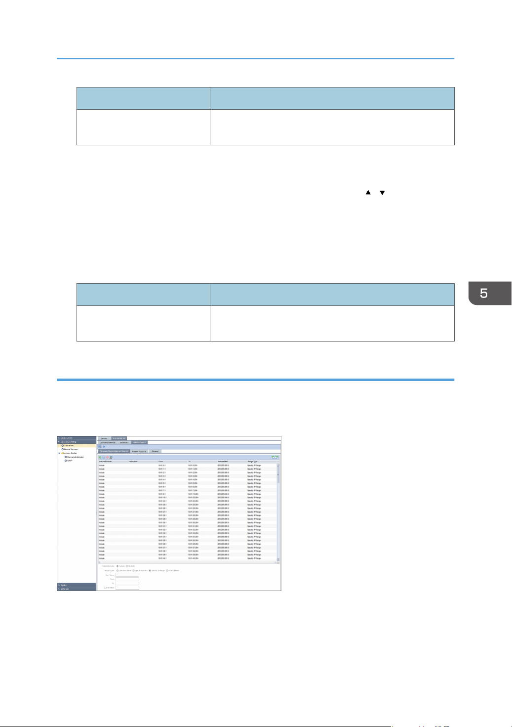
[Network Search] tab
Discovery tasks implemented by network search are displayed in a list.
A network search task is configured on the [Discovery Range (Network Search)], [Access Accounts],
and [General] tabs.
[Discovery Range (Network Search)] tab
Set the target range of discovery by network search.
53
Page 56
5. Discovery and Polling
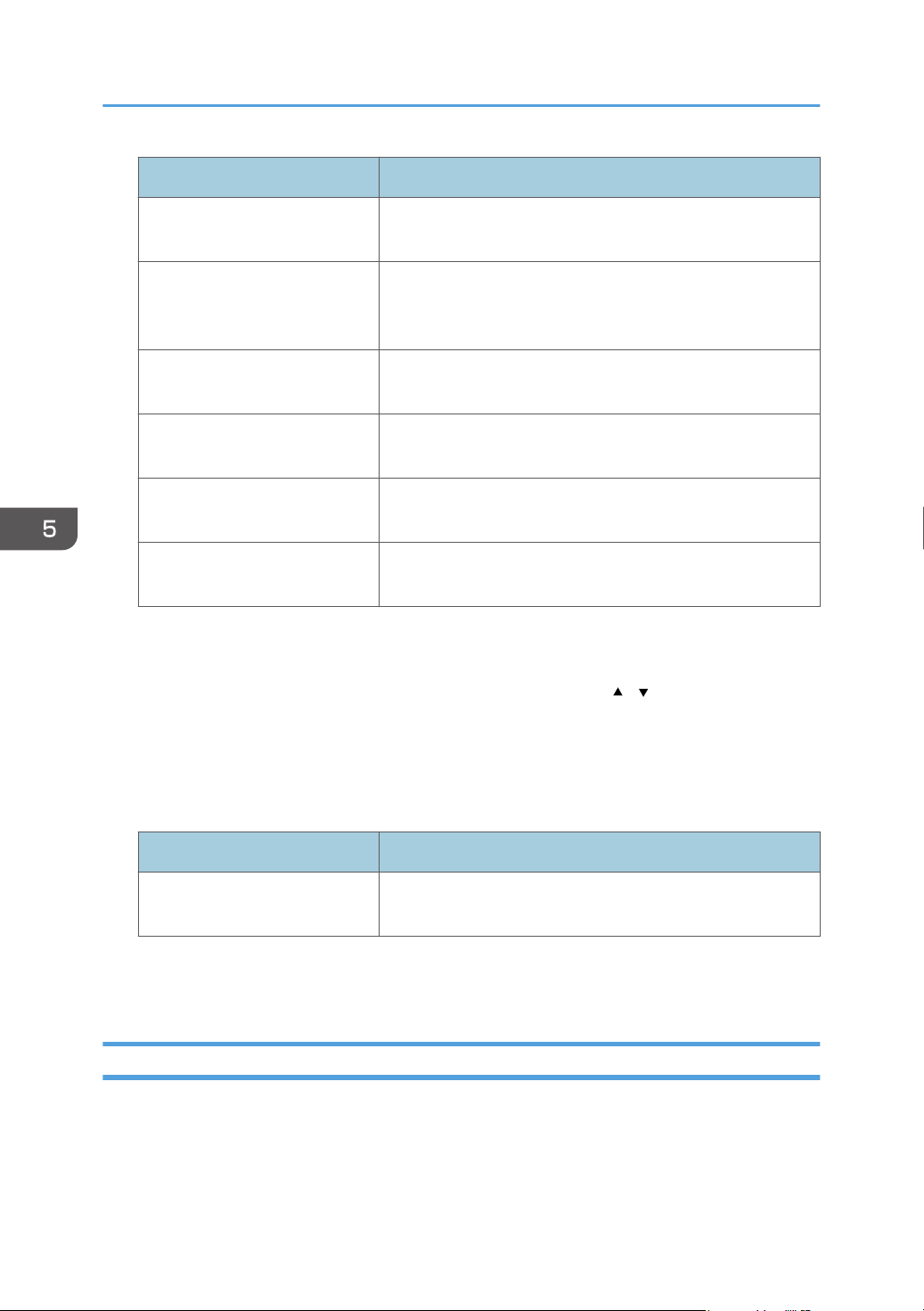
Item name Description
Include/Exclude Specify whether to include or exclude a specified range in
the network search.
Range Type Select [One Host Name], [One IP Address], [Specify IP
Range], or [IPv6 Address] as a type of the value to be
specified.
Host Name Specify this setting only if [Range Type] is set to [One Host
Name]. Use 1 to 255 characters.
From Enter the discovery target IP address, IPv6 address or start IP
address of the discovery target IP address range.
To Enter the end IP address of the discovery target IP address
range.
Subnet Mask Enter the subnet mask in the IP address range specified by
[From] and [To].
[Access Accounts] tab
Set an account used for access to devices at the time of discovery. Change the account to be used
from [Not Assigned Accounts] to [Assigned Account] by clicking the [
and dropping.
[General] tab
If the [Reverse DNS Lookup] is enabled, the machine attempts to determine the host name of the
device whose address has been detected. If the attempt fails, only the device address appears.
Item name Description
Reverse DNS Lookup Select this to enable the [Reverse DNS Lookup] to determine
device host names.
For an outline of the functions related to these settings and their operation, see page 62 "Searching for
Devices".
] [ ] button or by dragging
Manual Discovery
Specify the search range and search conditions for the device you want to search.
Manual Discovery task is configured on the [Discovery Range (Network Search)], [Access Accounts],
and [General] tabs.
54
Page 57
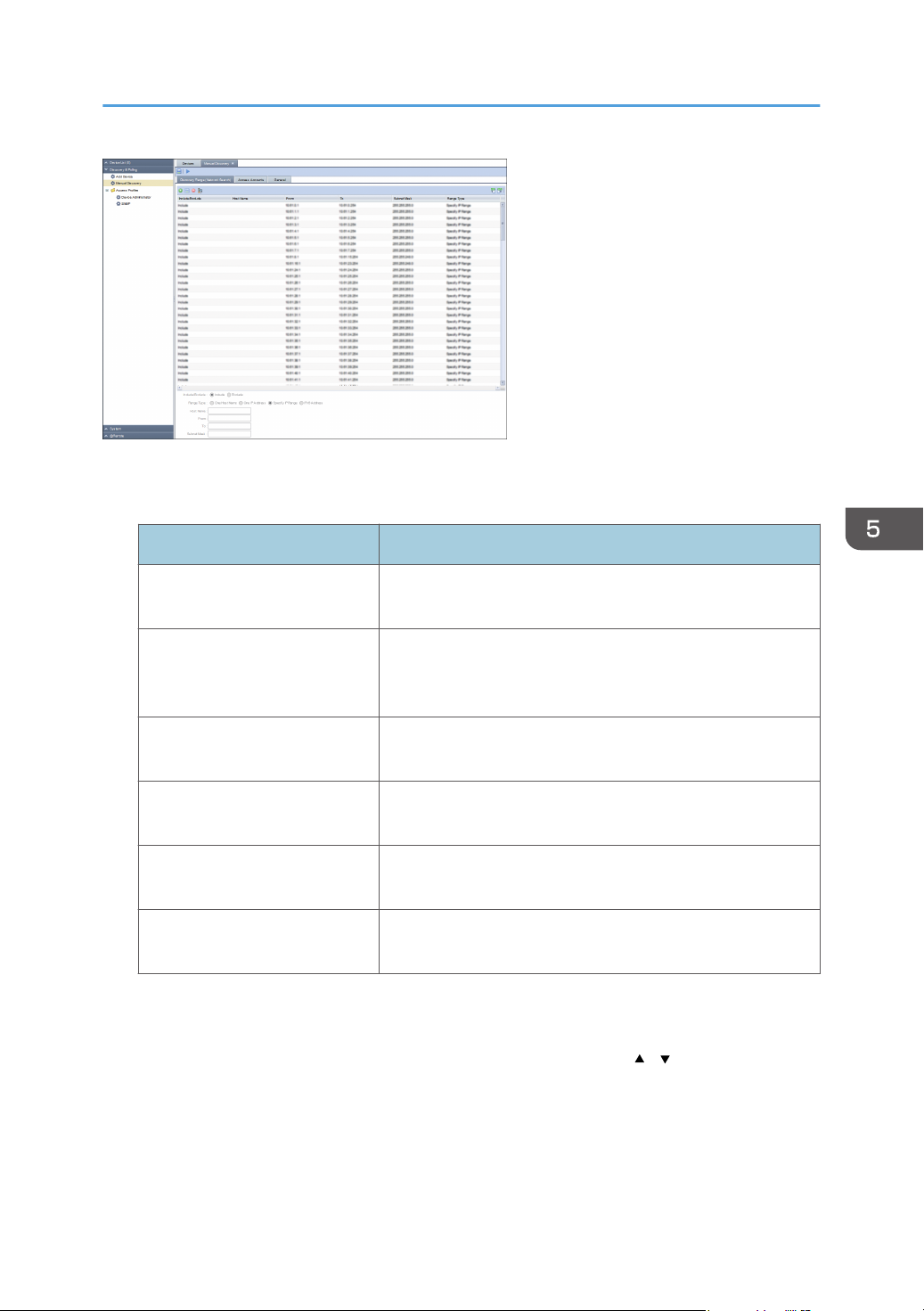
[Discovery Range (Network Search)] tab
Set the target range of discovery by network search.
Item name Description
Include/Exclude Specify whether to include or exclude a specified range in
the network search.
Discovery and Polling
Range Type Select [One Host Name], [One IP Address], [Specify IP
Range], or [IPv6 Address] as a type of the value to be
specified.
Host Name Specify this setting only if [Range Type] is set to [One Host
Name]. Use 1 to 255 characters.
From Enter the discovery target IP address, IPv6 address or start IP
address of the discovery target IP address range.
To Enter the end IP address of the discovery target IP address
range.
Subnet Mask Enter the subnet mask in the IP address range specified by
[From] and [To].
[Access Accounts] tab
Set an account used for access to devices at the time of discovery. Change the account to be used
from [Not Assigned Accounts] to [Assigned Account] list by clicking the [ ] [ ] button or by
dragging and dropping.
[General] tab
If the [Reverse DNS Lookup] is enabled, the machine attempts to determine the host name of the
device whose address has been detected. If the attempt fails, only the device address appears.
55
Page 58
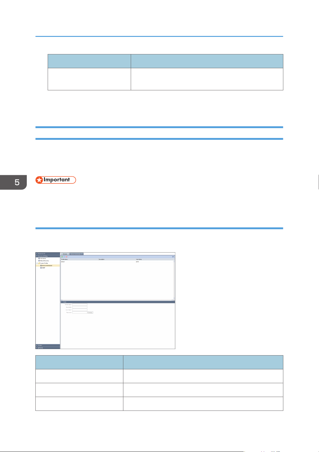
5. Discovery and Polling
Item name Description
Reverse DNS Lookup Select this to enable the [Reverse DNS Lookup] to determine
device host names.
For an outline of the functions related to these settings and their operation, see page 62 "Searching for
Devices".
Access Profiles
A list of the registered access accounts is displayed. An access account can be configured for [Device
Administrator] and [SNMP].
For details about how to configure access accounts, see page 59 "Configuring Access Accounts".
• To manage a device using the discovery and polling, make sure that the authentication information
of the access account matches the authentication information specified on the device.
Device Administrator
Indicates an access account that can be used for the Device Administrator in the list area. To display the
settings screen, click [Discovery & Polling] - [Access Profiles] and [Device Administrator].
Item name Description
Profile Name Enter a profile name. Use 1 to 255 characters.
Description Enter a profile description. Use 0 to 511 characters.
56
User Name User name is "admin". You can't change the user name.
Page 59
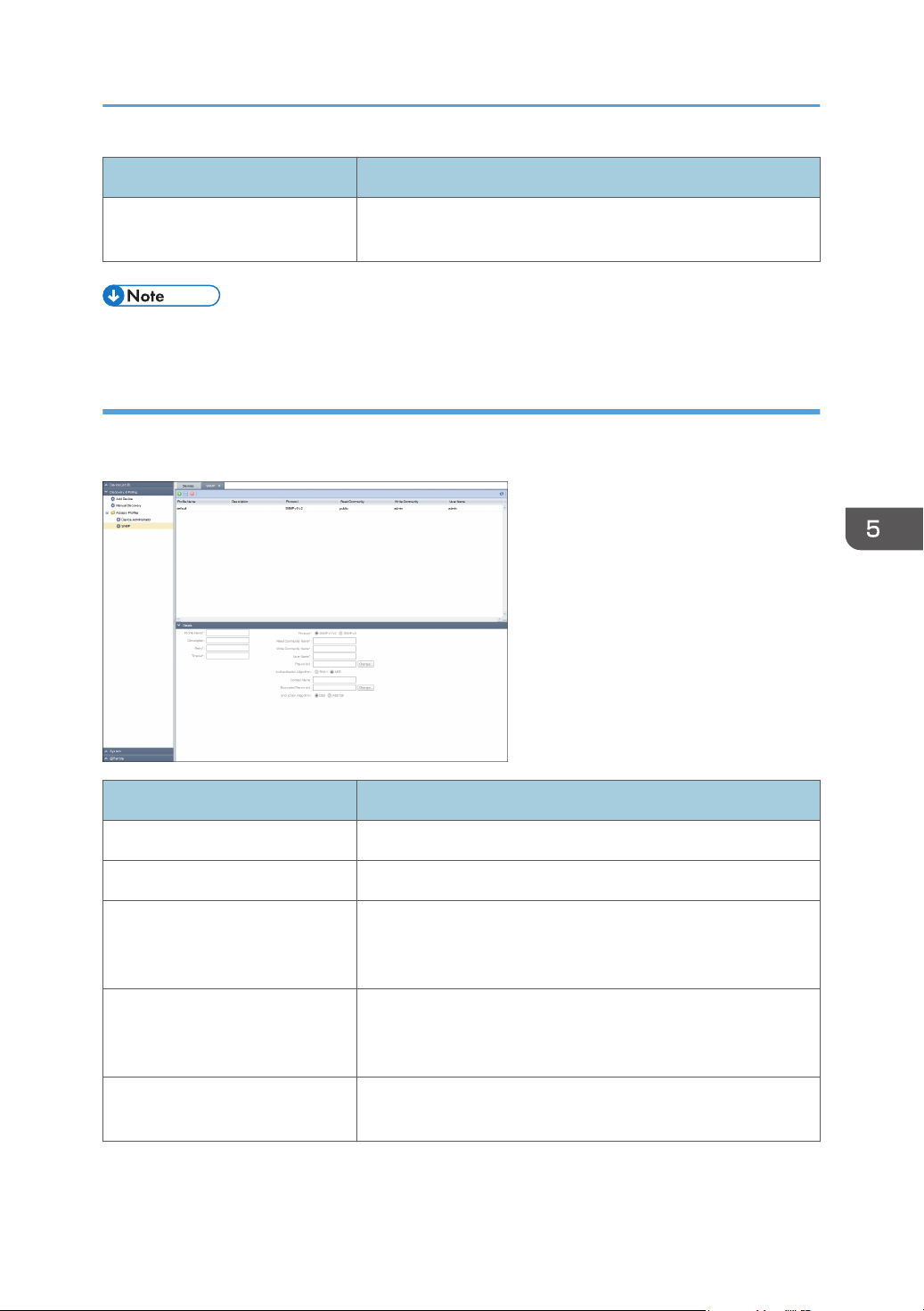
Discovery and Polling
Item name Description
Password Click [Change...], enter a changing password. Use up to 128
characters (ASCII character).
• "default" is registered as a default account in the system.
SNMP
Indicates an access account that can be used for SNMP protocol in the list area. To display the settings
screen, click [Discovery & Polling] - [Access Profiles] and [SNMP].
Item name Description
Profile Name Enter a profile name. Use 1 to 255 characters.
Description Enter a profile description. Use 0 to 511 characters.
Retry Specify how many retry attempts can be performed if a device
does not respond during discovery. Select from 0 to 5 attempts.
The default is 2 attempts.
Timeout Specify how long the waiting period can be if a device does not
respond during discovery. Any value between 500 and 60000
milliseconds can be specified. The default is 2000 milliseconds.
Protocol Select either [SNMP v1/v2] or [SNMP v3] as the protocol type.
Configuration items vary depending on protocol types.
57
Page 60
5. Discovery and Polling
Item name Description
Read Community Name Specify a read community name. Use 1 to 15 characters.
(SNMPv1/v2)
Write Community Name Specify a write community name. Use 1 to 15 characters.
(SNMPv1/v2)
User Name Enter a user name. Use 1 to 32 characters. (SNMPv3)
Password Click [Change...], enter a changing password. Use up to 128
characters (ASCII character). (SNMPv3)
Authentication Algorithm Select [MD5] or [SHA1] as the authentication algorithm.
(SNMPv3)
Context Name Enter a context name. Use 0 to 256 characters. (SNMPv3)
Encrypted Password Click [Change...], enter a changing password. Use up to 32
characters (ASCII character). (SNMPv3)
Encryption Algorithm Select [DES] or [AES128] as the encryption algorithm.
(SNMPv3)
• "default" is registered as a default account in the system.
58
Page 61
Configuring Access Accounts
Configuring Access Accounts
Specify user account information so that the RC Gate can access a device. Multiple accounts can be
configured in the RC Gate. If an account is created and its information is specified, the account can be
used with the discovery function and associated with devices.
Multiple accounts can be created for the device administrator account and SNMP account. The device
can be accessed in the specified order. An account that is successfully accessed is registered to the
device profile, and the registered device access account is used for future access to these devices.
By default, one access account is provided for the device administrator account and SNMP account.
These default SNMP access accounts can be edited but cannot be deleted.
Setting a SNMP Account
1. In the section area, click [Discovery & Polling].
2. In the [Access Profiles] category on the section tree, click [SNMP].
3. Click (Add) in the list area.
4. In the properties area, set [Profile Name], [Description], [Retry], and [Timeout] for the
account.
5. Select protocol [SNMP v1/v2] or [SNMP v3].
6. Specify values appropriate for the selected protocol.
For details about values that can be specified, see page 56 "Access Profiles".
7. Click (Save) when the setting is configured.
8. Click [OK].
Setting a Device Administrator Account
1. In the section area, click [Discovery & Polling].
2. In the [Access Profiles] category on the section tree, click [Device Administrator].
3. Click (Add) in the list area.
4. In the properties area, set [Profile Name], [Description], [Retry], [User Name], and
[Password] for the account.
5. Click (Save) when the setting is configured.
6. Click [OK].
59
Page 62
5. Discovery and Polling
Overwriting an Access Account
How to change and overwrite an access account of a detected device is explained below.
1. In the section area, click [Discovery & Polling].
2. In the [Access Profiles] category on the section tree, click the target account.
3. Select the profile name of the account that you want to change from the list area.
4. Click (Save) when the setting is complete.
5. Click [OK].
Deleting an Access Account
1. In the section area, click [Discovery & Polling].
2. In the [Access Profiles] category on the section tree, click the target account.
3. Select the profile name of the account that you want to delete from the list area.
4. Click (Delete).
5. Click [Yes] when a confirmation message appears.
6. Click [OK].
• The account may not be deleted depending on its state. For details, see page 106
"Troubleshooting".
60
Page 63
Specifying Access Profiles
Specifying Access Profiles
To configure access profile information, configure an SNMP account or device administrator account
profile according to page 59 "Configuring Access Accounts", and then select the access profile you
have created for the SNMP account or device administrator account according to page 61 "Specifying
Access Profiles".
SNMP
1. In the section area, click [Discovery & Polling].
2. In the [Add Device] category on the section tree, click [Broadcast] or [Network Search]
tab.
3. Click on the [Access Accounts] tab, and then select the access account you have created or
edited.
4. Click (Save).
Device Administrator
1. In the [Device List] section, click a target group to display the corresponding device list.
2. Select a target device in the list area.
3. Click [Access Accounts] in the [Device Administrator Access] in the properties area.
4. Select a profile from the "Profile Name:" pull-down menu.
5. Click (Save).
• If there are more than one Device Administrator accounts, first select the one that is used on the
largest number of devices as the default settings, and then select the accounts for the other devices
one by one.
61
Page 64
5. Discovery and Polling
Searching for Devices
You can use the RC Gate to search for devices on a network by using the discovery function and to
detect monitoring and control target devices.
Before using the discovery function, set search conditions such as the IP address range, model name,
and status.
The following two methods are available when using discovery on a network:
Network Search
A specified IP address range is used for network search. Each of the IP addresses within the IP
address range will be accessed using SNMP.
Broadcast
SNMP broadcast is performed for all devices on a local or specified network so as to detect
devices that are connected to the network.
• The discovery function can detect devices that are compatible with Printer MIB v2 (RFC 3805),
Printer MIB (RFC 1759), MIB-II (RFC 1213), and Host Resource MIB (RFC 2790).
Search the Device
1. In the section area, click [Discovery & Polling].
2. Click [Add Device] on the section tree.
3. Click the [Broadcast] or [Network Search] tab, and then click the [Discovery Range] tab.
• Click
• If a CSV file that specifies a search range is imported:
For details, see page 33 "Importing a CSV File".
• Auto Retrieve Router:
(Add) on the list area.
1. Specifying settings is possible when the half-bright highlighted setting item changes to
bright highlighted one.
2. To register a device, configure search conditions such as the IP address range, model
name, and status of the device.
1. Click (Auto Retrieve Router).
2. Select [Number of Search Hops] and then configure the access account.
On the [Access Accounts] tab, you can specify all access accounts.
3. Click [Start Retrieval].
Automatic retrieval starts.
62
Page 65
Searching for Devices
You cannot check the overlaps of the discovery range before clicking the button and the
discovery range added by clicking the button.
The items that can be specified vary depending on whether [Network Search] or [Broadcast] is
specified. Click (Export data to a CSV file) to export the set search range as a CSV file.
4. Click (Save) when the setting is configured.
A discovery task is registered to the list. To immediately perform discovery, click (Immediately
perform).
• Select the discovery range that is already registered to the list area and edit the settings in the
property area. To save edited settings, click (Save).
• To delete a discovery range, select the discovery range to be deleted, and click (Delete).
• New devices may be added to the network. To find additional devices on the network after the
initial network configuration, perform discovery again.
• For details on the configuration items of each tab, see page 51 "Add Device".
Search the Device Again
This is the procedure for avoiding possible inconsistencies between the device information managed by
the RC Gate and the actual device information that may occur due to changing the IP address of the
device or other operation.
1. In the section area, click [Discovery & Polling].
2. Click [Manual Discovery] on the section tree.
• Click (Add) on the list area:
1. Specifying settings is possible when the half-bright highlighted setting item changes to
bright highlighted one.
2. To register a device, configure search conditions such as the IP address range, model
name, and status of the device.
• If a CSV file that specifies a search range is imported:
For details, see page 33 "Importing a CSV File".
• Auto Retrieve Router:
1. Click (Auto Retrieve Router).
2. Select [Number of Search Hops] and then configure the access account.
On the [Access Accounts] tab, you can specify all access accounts.
3. Click [Start Retrieval].
Automatic retrieval starts.
63
Page 66
5. Discovery and Polling
You cannot check the overlaps of the discovery range before clicking the button and the
discovery range added by clicking the button.
The items that can be specified vary depending on whether [Network Search] or [Broadcast] is
specified. Click (Export data to a CSV file) to export the set search range as a CSV file.
3. After filling all the fields, click (Save), and then click (Immediately perform).
Retrieve data to identify the device.
4. Check the device in [Discovered Managed Devices], and then click [OK].
Registering a Device to the RS Center System
This section explains how to register a device to the RS Center System.
When registering a device, be sure to add it to the [Discovered Devices] tab function in advance. For
details about add device, page 62 "Search the Device".
1. In the section area, click [Discovery & Polling].
2. Click [Discovered Devices] in [Add Device] in the section tree.
If the added device does not appear in the list area, click (Refresh). Repeat this process in
accordance with the procedure described on page 62 "Search the Device" until the added device
appears in the list area.
3. When the device information appears, right-click on the device you want to register in
[Display Name] in the list area, and then click [Register].
You can also register by clicking the (@Remote) icon in the list area.
4. Check that the device to be registered appears in the [Confirmed View], and then click
[OK].
If registering a device to the RS Center System fails, "Failed" appears in the [Result] field with the
cause of failure displayed in the [Cause] field. Take appropriate measures according to the cause
of the failure displayed in the [Cause] field.
5. In the [Registration Result], click [OK].
6. To display the registered device, click the (Refresh) in the device list.
If the group tree has not been updated, right-click in the section area and update the list.
64
Page 67
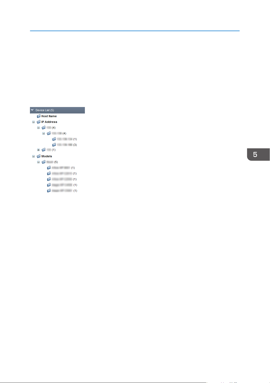
Classifying Devices by Group Name
Classifying Devices by Group Name
Monitoring and management of devices can be facilitated if devices are grouped by category such as
installation site and user.
Automatic groups
The RC Gate classifies devices automatically. Groups [Host Name], [IP Address], and [Models]
are provided.
When registered, devices are grouped automatically by each category.
The section tree structure is displayed with low-layer groups expanded/collapsed when the "+" / "-"
icon next to the group (folder) icon is clicked.
65
Page 68
5. Discovery and Polling
66
Page 69
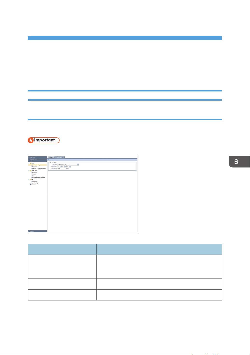
6. System
This chapter explains the items that appear in the System.
System Settings
Setup
Date/Time Settings
You can confirm and change the clock of the RC Gate. To display the settings screen, click [System] [Setup] and [Date/Time Settings].
• Check the time and date regularly, and correct them if necessary.
Date/Time Settings
Item Description
Time zone The standard time of the place where the RC Gate is set (The
time zone indicates the time difference from Universal
Coordinated Time).
Date Settings Set the current date of the place where the RC Gate is set.
Time Settings Set the current time of the place where the RC Gate is set.
67
Page 70
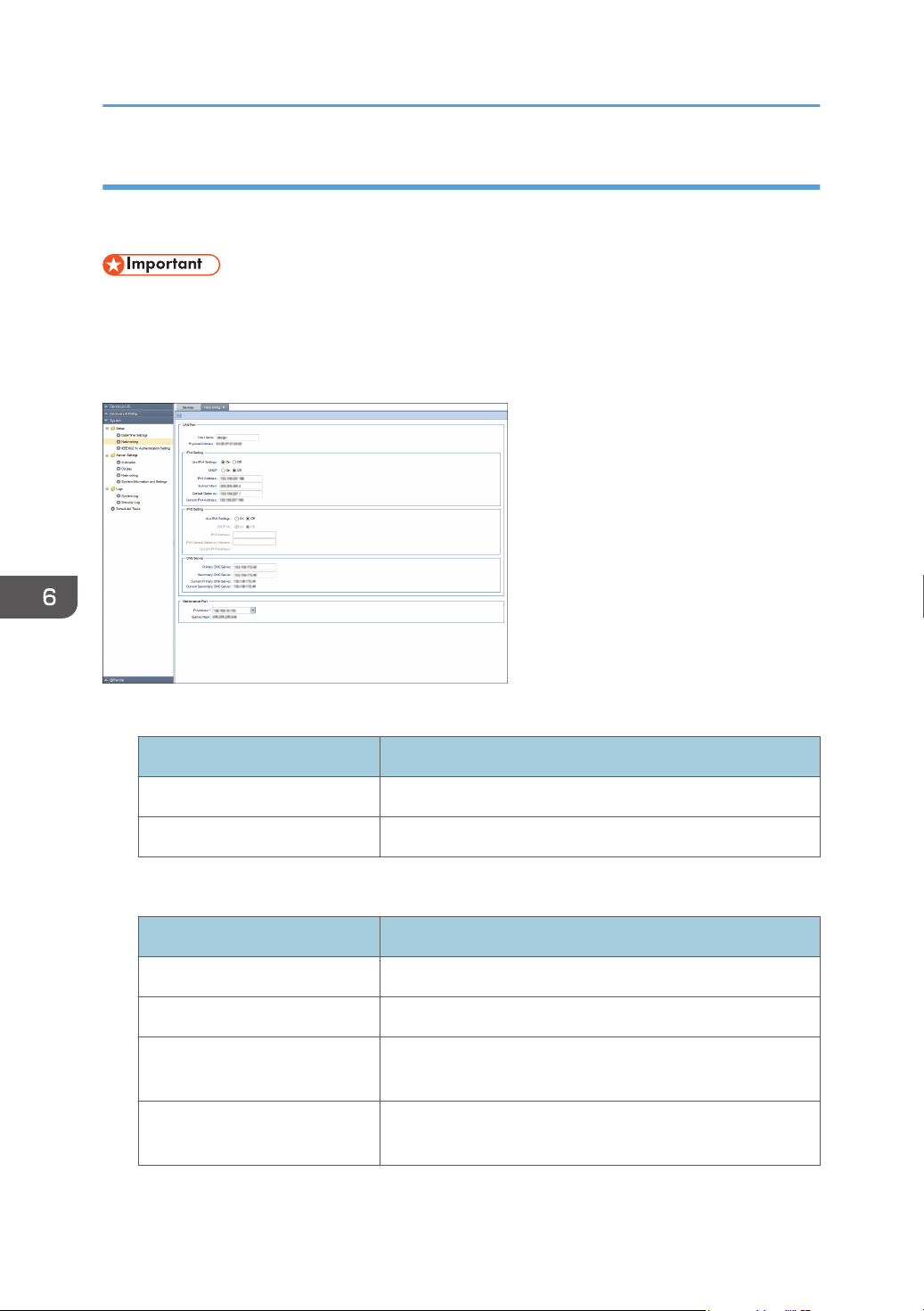
6. System
Networking
You can change and confirm the network settings of the RC Gate. To display the settings screen, click
[System] - [Setup] and [Networking].
• After changing the network settings, you have to log in to the RC Gate again. Using the changed
address, open the new URL with the web browser.
• After changing the DNS server setting, reboot the machine. (You do not need to reboot the
machine after configuring the initial setting.)
LAN Port
Item Description
Host Name A host name for the RC Gate.
Physical Address A MAC address for the PC port.
[LAN Port] - [IPv4 Setting]
Item Description
Use IPv4 Settings Select whether or not to use IPv4 server.
DHCP Select whether or not to use DHCP server.
IPv4 Address An IPv4 address for the RC Gate (LAN port). You can specify
this setting only if DHCP is set to [OFF].
Subnet Mask A subnet mask for the RC Gate. You can specify this setting
only if DHCP is set to [OFF].
68
Page 71
Item Description
Default Gateway A gateway address for the RC Gate. You can specify this
setting only if DHCP is set to [OFF].
Current IPv4 Address Displays the current IPv4 address.
[LAN Port] - [IPv6 Setting]
Item Description
Use IPv6 Settings Select whether or not to use IPv6 server.
DHCP v6 Select whether or not to use DHCP v6 server.
IPv6 Address An IPv6 address for the RC Gate (LAN port).
You can Enter it when DHCP v6 is set to [Off].
IPv6 Default Gateway Address A gateway address for the RC Gate (LAN port).
System Settings
Current IPv6 Address Displays the current IPv6 address.
[LAN Port] - [DNS Server]
Item Description
Primary DNS Server Enter the IP address of the DNS server which the RC Gate
mainly uses. Enter the IP address in "x.x.x.x" format ("x" stands
for a number from 0 to 255). You may enter the IPv6
address.
Secondary DNS Server Enter the IP address of a secondary DNS server to use a
secondary DNS server when a primary DNS server cannot
be used for some reason. Enter the IP address in "x.x.x.x"
format ("x" stands for a number from 0 to 255). You may
enter the IPv6 address.
Current Primary DNS Server Displays the current primary DNS server address.
Current Secondary DNS Server Displays the current secondary DNS server address.
Maintenance Port
This setting can be accessed only at the initial setting.
69
Page 72
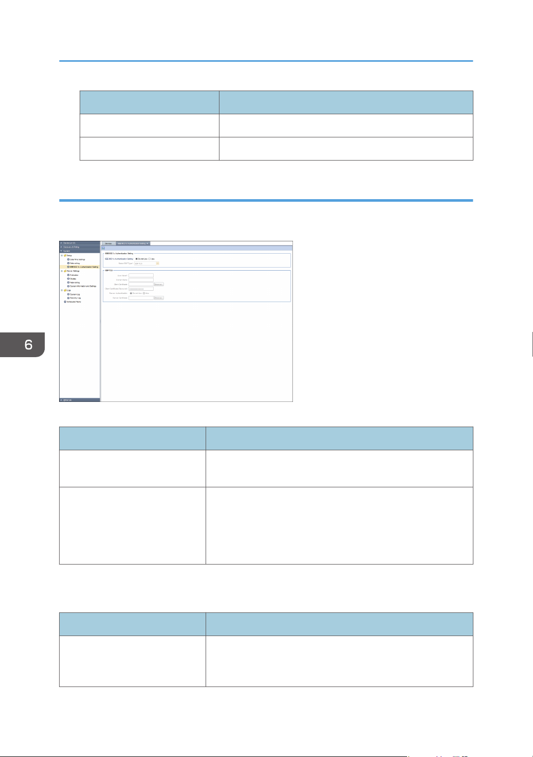
6. System
Item Description
IP Address An IP address for the USB 2.0 interface (Maintenance port).
Subnet Mask A subnet mask for the USB 2.0 interface (Maintenance port).
IEEE 802.1x Authentication Setting
You can specify the setting for IEEE 802.1x authentication. To display the settings screen, click [System] [Setup] and [IEEE 802.1x Authentication Setting].
IEEE 802.1x Authentication Setting
Item Description
IEEE 802.1x Authentication
Set whether to enable IEEE 802.1x authentication.
Setting
Select EAP Type Authentication type can select the following item:
• EAP-TLS
• PEAP
• EAP-TTLS
The item selected in [Select EAP Type] appears as follows:
EAP-TLS
Item Description
User Name The login user name for the authentication server. Use 1 to 96
characters (ASCII characters). You cannot use " (double
quotation) and ' (single quotation) marks.
70
Page 73
System Settings
Item Description
Domain Name The login domain name for the authentication server. Use 1 to
96 characters (ASCII characters).
Client Certificate Click [Browse...] to select the certificate.
Client Certificate Password Enter the password required. Use up to 128 characters (ASCII
character). You cannot use " (double quotation) and ' (single
quotation) marks.
Server Authentication Set whether to enable the server authentication that uses route
certificate.
Server Certificate This is displayed only when the authentication is [Use]. Click
[Browse...], upload the certificate.
PEAP
Item Description
User Name The login user name for the authentication server. Use 1 to 96
characters (ASCII characters). You cannot use " (double
quotation) and ' (single quotation) marks.
Domain Name The login domain name for the authentication server. Use 1 to
96 characters (ASCII characters).
Tunneling Method Set the tunneling method.
Tunneling User Name Set the user name. Use 1 to 31 characters (ASCII characters).
Tunneling Password Enter the certificate password. Use up to 128 characters (ASCII
character).
Server Authentication Set whether to enable the server authentication.
Server Certificate This is displayed only when the authentication is [Use]. Click
[Browse...], and then upload the certificate.
EAP-TTLS
Item Description
User Name The login user name for the authentication server. Use 1 to 96
characters (ASCII characters). You cannot use " (double
quotation) and ' (single quotation) marks.
71
Page 74
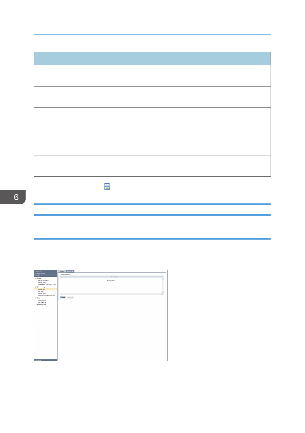
6. System
Item Description
Domain Name The login domain name for the authentication server. Use 1 to
96 characters.
Tunneling Method Set the tunneling method to MSCHAPv2, PAP, CHAP or
MSCHAP.
Tunneling User Name Set the user name. Use 1 to 31 characters (ASCII characters).
Tunneling Password Enter the certificate password. Use up to 128 characters (ASCII
character).
Server Authentication Set whether to enable the server authentication.
Server Certificate This is displayed only when the authentication is [Use]. Click
[Browse...], upload the certificate.
After registering all items, click (Save).
Server Settings
Activation
To use the counter per user function, you need to register the license by activation. When the activation
is complete, the activated license appears in the list area. To display the settings screen, click [System] [Server Settings] and [Activation].
72
Page 75
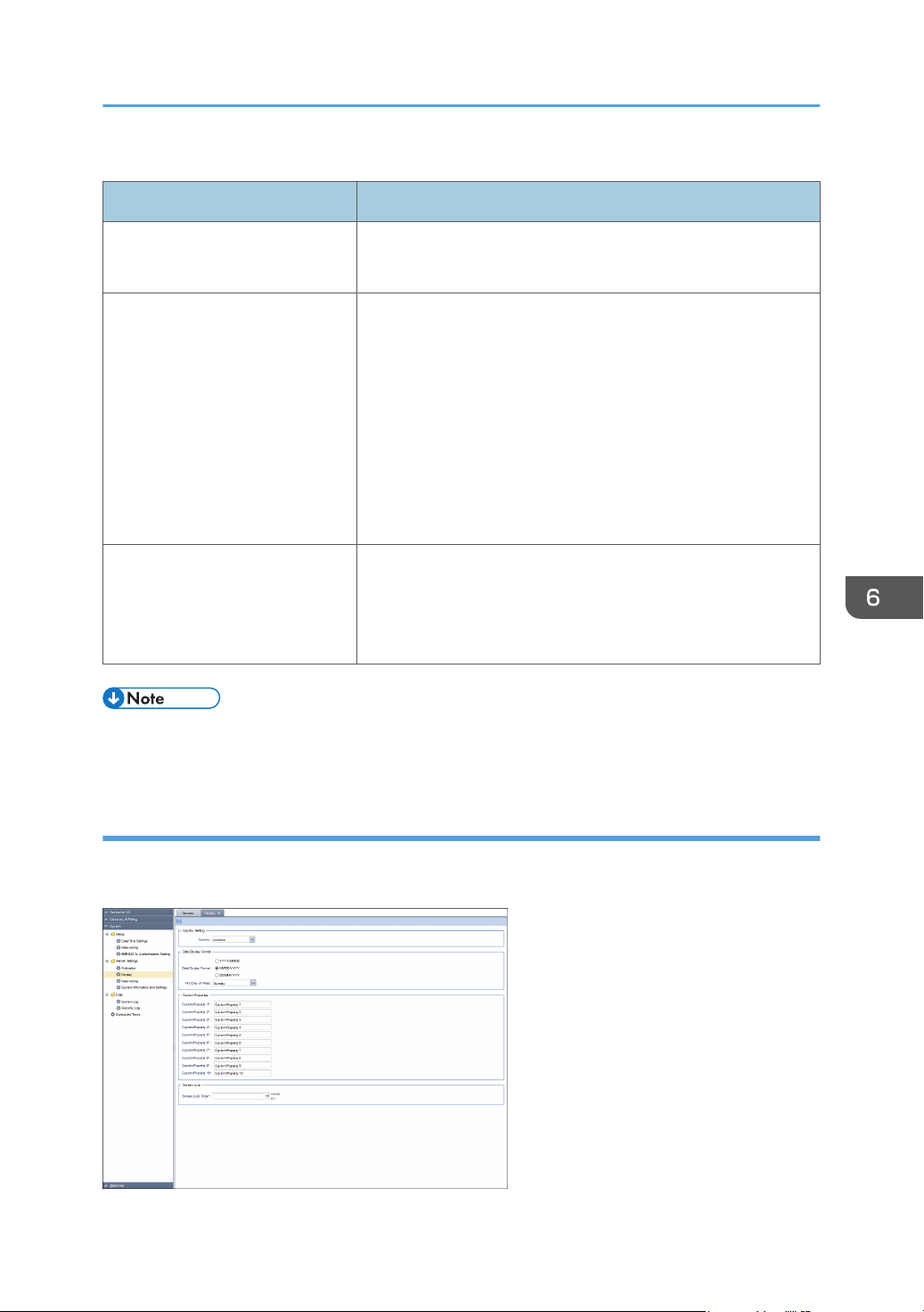
System Settings
Activation/Deactivation
Item Description
[Activated license] field Displays the activated license on the [Activated license] field.
Only one license can be activated.
[Activation] button Activates a license.
This button can be only if [Activated license] field is blank.
This button cannot be used if [Activated license] field is not blank.
Click [Activation] and then specify the following settings, and
then click [OK].
• Product Key
• Country
• Organization
[Deactivation] button Deactivates the activated license.
If you select an activated license from [Activated license] field
and click [Deactivation] button, the deactivation confirmation
message appears.
• For the functional outlines or operations of these setting items, see page 84 "Activating the RC
Gate".
Display
You can configure the date display format and other related settings for the RC Gate. To display the
settings screen, click [System] - [Server Settings] and [Display].
73
Page 76
6. System
Country Setting
Item Description
Country Specify [Country Setting] in [System] section. The default is
Andorra.
Date Display Format
Item Description
Date Display Format Select from the following date display formats:
• YYYY/MM/DD
• MM/DD/YYYY
• DD/MM/YYYY
First Day of Week You can select the date to start the week in the calendar
displayed in the settings.
Custom Properties
Item Description
Custom Property 1 - 10 Set the item names of custom properties. Use 1 to 255
characters.
For the functional outlines or operations of these setting items,
see page 49 "Setting custom properties".
Screen Lock
Item Description
Screen Lock Timer Set the screen lock to between 1 - 60 minutes. You can disable
the screen lock function by entering the password again on the
login screen.
Networking
Configure the proxy server setting for Internet access. To display the settings screen, click [System] [Server Settings] and [Networking].
• After changing the SSL/TLS setting, reboot the machine.
74
• Specify settings so that the machine and main unit, and browser and main unit can be used in a
shared-usage mode.
Page 77
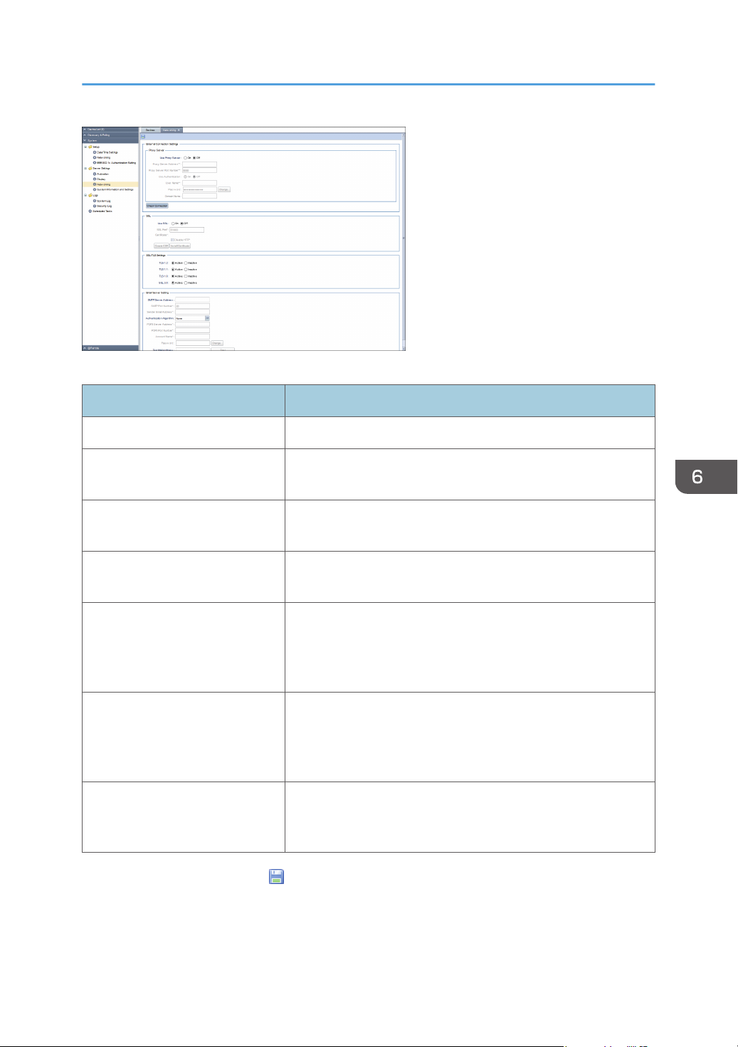
[External Connection Settings] - [Proxy Server]
Item Description
Use Proxy Server Specify whether or not to use a proxy server.
Proxy Server Address Enter the IP address of the proxy server. Use 1 to 255
characters.
System Settings
Proxy Server Port Number Enter the port number of the proxy server. Use 1 to 65535
numbers.
Use Authentication Specify whether or not to apply user authentication to the proxy
server.
User Name Enter the user name to use for authentication of the proxy server.
Click [Change...], enter a changing password. Use 1 to 256
characters. This item is enabled only when [Use Authentication] is
[On].
Password Change the password to use for authentication of the proxy
server. Click [Change...], enter a changing password. Use 0 to
256 characters. This item is enabled only when [Use
Authentication] is [On].
Domain Name Enter the domain name you want to use for NTLM authentication
of the proxy server. Use 0 to 256 characters. This item is
enabled only when [Use Authentication] is [On].
After configuring all settings, click (Save) and click the [Check Connection] button. A connection test
is executed using the proxy server.
75
Page 78
6. System
SSL
Item Description
Use SSL Select whether or not to use SSL.
SSL Port Enter the port of the SSL. Use 1 to 65535 numbers.
Certificate Create and install the device certificate.
In [Create CSR], enter Request Number, and then execute
[Install Certificate] to upload the certificate.
To disable HTTP, select [Disable HTTP].
SSL/TLS Settings
Item Description
TLS 1.2 Specifies whether connection is set to [Active] or [Inactive].
TLS 1.1 Specifies whether connection is set to [Active] or [Inactive].
TLS 1.0 Specifies whether connection is set to [Active] or [Inactive].
SSL 3.0 Specifies whether connection is set to [Active] or [Inactive].
You cannot disable all network settings. Specify settings so that the machine and main unit, and browser
and main unit can be used in a shared-usage mode.
After configuring settings, click (Save). The RC Gate reboots itself to apply the specified setting.
Email Server Setting
Item Description
SMTP Server Address Enter the IP address of the SMTP server. Use 0 to 255
characters.
SMTP Port Number Enter the port number of the SMTP server. Use 1 to 65535
numbers.
Sender Email Address Specify the sender address of an e-mail the system sends. Use 1
to 256 characters.
Authentication Algorithm Select the authentication algorithm.
POP3 Server Address Enter the IP address for POP3 server. Use 1 to 256 characters.
76
POP3 Port Number Enter the port number for POP3 server. Use 1 to 65535
numbers.
Page 79
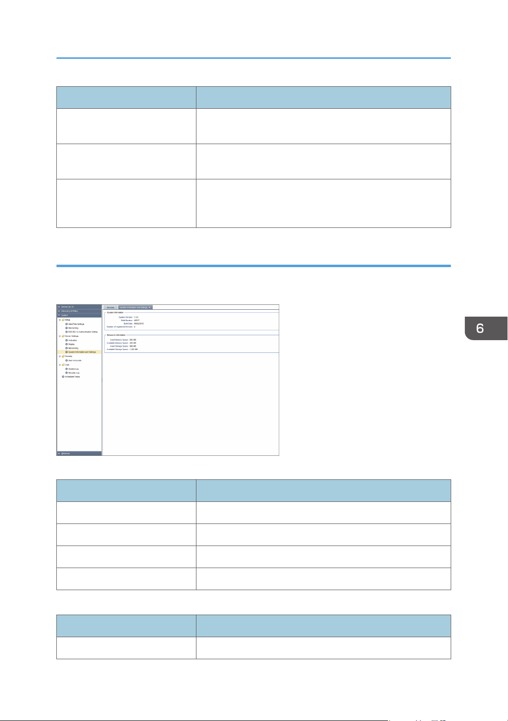
System Settings
Item Description
Account Name Enter the account name for POP3 and SMTP. Use 1 to 256
characters.
Password Click [Change...], enter the user password for POP3 and SMTP.
Use 0 to 256 characters.
Test Mail Address Enter an e-mail address for POP3 and SMTP. Use 1 to 256
characters. You can execute the connection test by clicking
[Test].
System Information and Settings
You can check the information for the RC Gate. To display the settings screen, click [System] - [Server
Settings] and [System Information and Settings].
System Information
Item Description
System Version You can check the system version.
Build Number You can check the build number.
Build Date You can check the build date.
Number of registered Devices You can check the number of registered devices.
Resource Information
Item Description
Used Memory Space You can check the used memory space.
77
Page 80
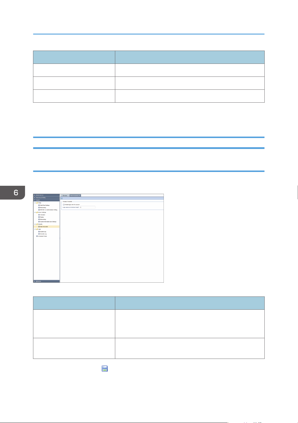
6. System
Item Description
Available Memory Space You can check the available memory space.
Used Storage Space You can check the used storage space.
Available Storage Space You can check the available storage space.
If an SD expansion card is installed, the occupied and available capacities of the external storage also
appear.
Security
User Accounts
Match the settings with those of the CC-certified environment. To display the settings screen, click
[System] - [Security] and [User Accounts].
Access Accounts
Item Description
Prohibit login with CE account Check this to prevent the customer engineer from logging in. If
Login password minimum length You can specify the minimum number of characters required for
After configuring settings, click (Save).
78
you forget the password while the check box is selected, the
customer engineer cannot reset the password.
the login password. The default is 8 characters.
Page 81
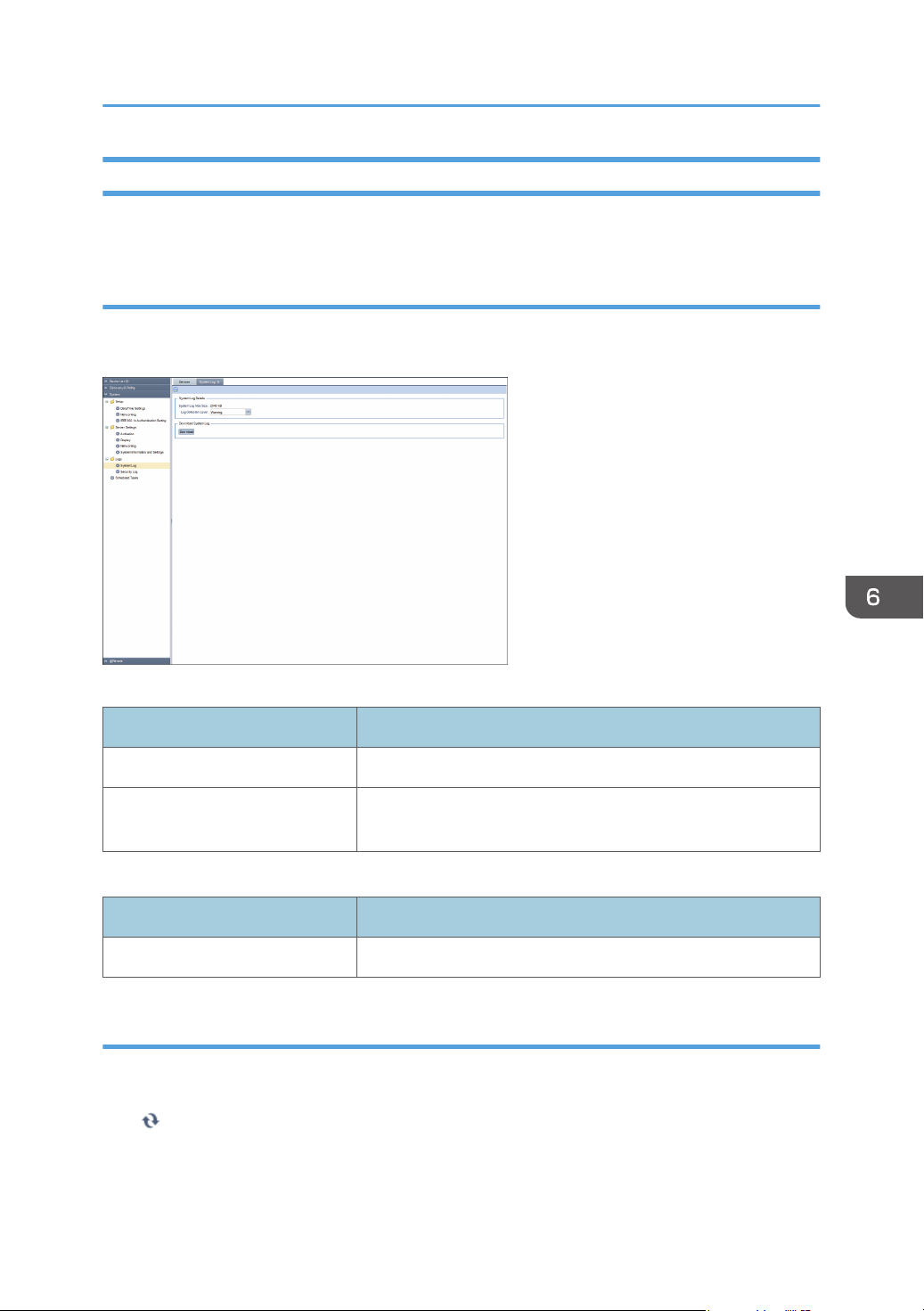
System Settings
Logs
In the RC Gate, you can check the following system operation logs.
System Log
You can download the internal system operation log to analyze the system log at the time the error
occurred. To display the settings screen, click [System] - [Logs] and [System Log].
System Log Details
Item Description
System Log Max Size Indicates the maximum size of system log.
Log Collection Level Adjust the log collection level to a suitable level for analyzing the
error.
Download System Log
Item Description
[Download] (button) You can download the system log file by clicking [Download].
Security Log
The security log contains a list of security-related events, such as logins, logouts, and system changes. To
display the security log, click [System] - [Logs] and [Security Log].
Click (Refresh) to obtain the latest log.
79
Page 82
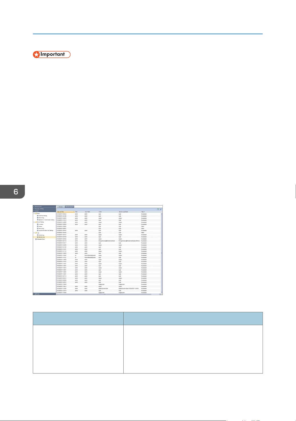
6. System
• Under the following operating conditions, about 28 log entries are generated each day. Because
the Maximum number of security log entries is 5,824, about 208 days of records can be stored in
the security log (5,824 divided by 28 = 208).
• Administrator logs in and out once a day.
• Device polling occurs once an hour.
• It is recommended that you check the security log at least once every 104 days (about 15 weeks)
to ensure that logs are not overwritten before you view them. Check the security log more
frequently if your usage is greater than that given above.
• If the number of security log entries exceeds the maximum, new entries will overwrite the oldest
entries, regardless of whether or not the log has been checked.
• When checking the log, make sure to check that your most recent login information is displayed. If
your most recent login information is not displayed, contact your service representative.
• If the security log is not saved immediately, it may be that downloading is taking time. Wait a while.
• If the security log cannot be displayed or saved, try a different web browser. If the problem persists
even with a different web browser, shut down the RC Gate, and then contact your service
representative.
The following table explains the information that is displayed for one entry in the security log.
Item Description
Date and Time Displays the date and time of the log entry according to the
local time specified in [Time zone] in [Date/Time Settings] in
[Setup] in [System].
m-d-y H:M:S
y: year, m: month, d: day, H: hour, M: minute, S: second
80
Page 83
Item Description
Role The type of user who accessed the RC Gate.
• RC Gate administrator: "admin"
• Customer engineer: "ce"
• RS Center System: "center"
• System: "System"
*1
User Name Displays a user name.
• RC Gate administrator: "admin"
• Customer engineer: "Ricoh AtRemote Operator"
Action The event that caused the log to be recorded.
• Power on: "Logging start"
• Power off: "Logging end"
• Login: "Login"
System Settings
• Logout: "Logout"
• Lockout: "Lockout"
• Update account: "Update account (Updated account
name)"
*2
• Get system log: "Get system log"
• Get security log: "Get security log"
• Update system clock: "Update System Clock (Updated
*2
time)"
• Update system firmware: "Update system firmware
(Firmware version)"
*2
• Validate system firmware: "Validate system firmware
(Firmware version)"
*2
• Update system @Remote certificate: "Update system
@Remote certificate"
• SSL communication error: "SSL communication error"
• Update Device @Remote Certificate: "Update device
auth. Key (Updated value)"
*2
• Change Device @Remote Certificate: "Change
encryption length (Updated value)"
*2
• Change SSL/TLS Settings: "Change SSL Protocols
(Active SSL Protocols)"
*2
81
Page 84
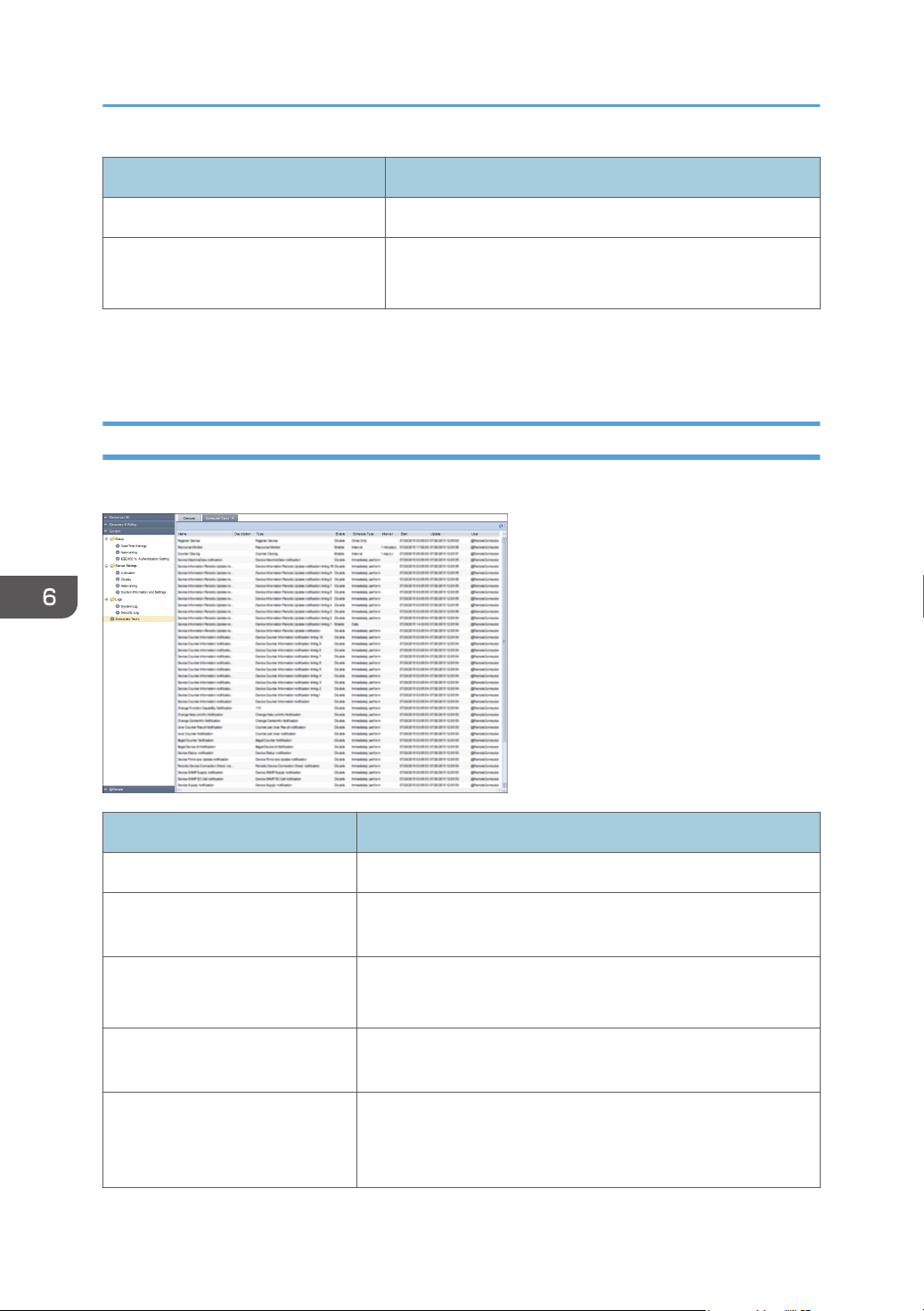
6. System
Item Description
Security Log Details Displays the details of the security log.
Result • Succeeded: "Succeeded"
• Failed: "Failed"
"System" refers to the RC Gate itself.
*1
Details of "(****)" appear in [Security Log Details].
*2
Scheduled Tasks
You can check the scheduled tasks. To display the settings screen, click [System] - [Scheduled Tasks].
82
Item Description
Name This is the task name entered when the task was registered.
Description This is the description of task entered when the task was
registered.
Type Indicates the task type.
ex) Discovery, Status Polling
Enable Indicates whether the schedule for the task is enabled or
disabled.
Schedule Type Indicates the schedule settings.
ex) Immediately perform/Once Only/Interval/Repeatedly/
Daily
Page 85
System Settings
Item Description
Interval Indicates the interval if [Schedule Type] is set to [Interval].
Start Indicates when the task starts.
Update Indicates when the task was created or edited.
User Indicates who created or edited the task.
• In the scheduled task list, you cannot change the schedule or remove the task.
83
Page 86
6. System
Activating the RC Gate
Connect to the Internet directly from the RC Gate and activate the product.
This function is required to use the counter per user function. When a proxy server is required to access
the Internet, configure the required settings in the [Proxy Server] in the [Networking] in the [Server
Settings] category under the [System] section. For details about proxy server, see page 74
"Networking". When using the DNS server, the activation fails if the settings are not specified correctly.
For details about DNS server settings, see page 68 "Networking".
• If the product is not deactivated before the network interface is replaced, consult your sales or
service representative.
Activating
Connect to the Internet directly from the RC Gate and activate the product.
1. Click the [System] section.
2. Click [Activation] under [System Settings].
3. Click [Activation] button.
4. Enter the product key.
Enter the product key that you purchased.
5. Select the country where the product is used in [Country].
Activation is performed even if this setting is not specified.
6. Enter the organization in [Organization].
Use 0 to 250 characters. Activation is performed even without making this entry.
7. Click [OK].
Deactivating the Product
Make sure to deactivate the RC Gate first, and then uninstall the product. This procedure is required to
re-use the product key again.
• You cannot use the counter per user function after the product has been deactivated.
Connect to the Internet directly from the RC Gate and deactivate the product. When a proxy server is
required to access the Internet, configure the required settings in the [Proxy Server] in the [Networking]
84
Page 87
Activating the RC Gate
in the [Server Settings] category under the [System] section. For details about proxy server, see page 74
"Networking".
1. Click the [System] section.
2. Click [Activation] under [System Settings].
3. Click [Deactivation] button.
4. Click [OK].
Deactivation is performed, and then a dialog box reporting the result appears.
85
Page 88
6. System
86
Page 89
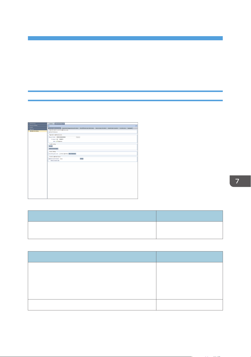
7. @Remote
This chapter explains the items that appear in the @Remote.
@Remote Settings
Connect to @Remote System
You can configure connector settings. To display the settings screen, click [@Remote] - [@Remote
Settings] and [Connect to @Remote System] tab.
Select Information to send to the @Remote center
Item Detail
Send IP addresses Check this to send your IP
address to RS Center System.
Registration to @Remote System
Item Detail
Request Number Input the request number to
connect to the RS Center System.
If the registration has already
been made, you do not need to
make an entry.
RC Gate ID Displays the RC Gate ID.
87
Page 90
7. @Remote
Item Detail
Status Displays the status of server
registration to the RS Center
System.
Trouble shooting
Item Detail
[Test Call] button Check that a test call can be
enabled to the RS Center System.
[Confirm Communication] button Attempts connecting to the RS
Center System. If the connection
fails, its reason appears in
details.
Security Settings
Item Detail
Device Encryption Level Change the encryption length to
2048 bit in accordance with the
CC-certified environment.
By selecting 2048bit and
clicking [Batch Modification], the
selected encryption key length is
applied to all the devices.
Connect to @Remote System
Item Detail
@Remote System Address Indicates the RS Center System.
Clicking [Change], you can
change the RS Center System's
e-mail address in [@Remote
System Address] windows.
Failed connection date Indicates when the connection to
RS Center System failed.
88
Page 91
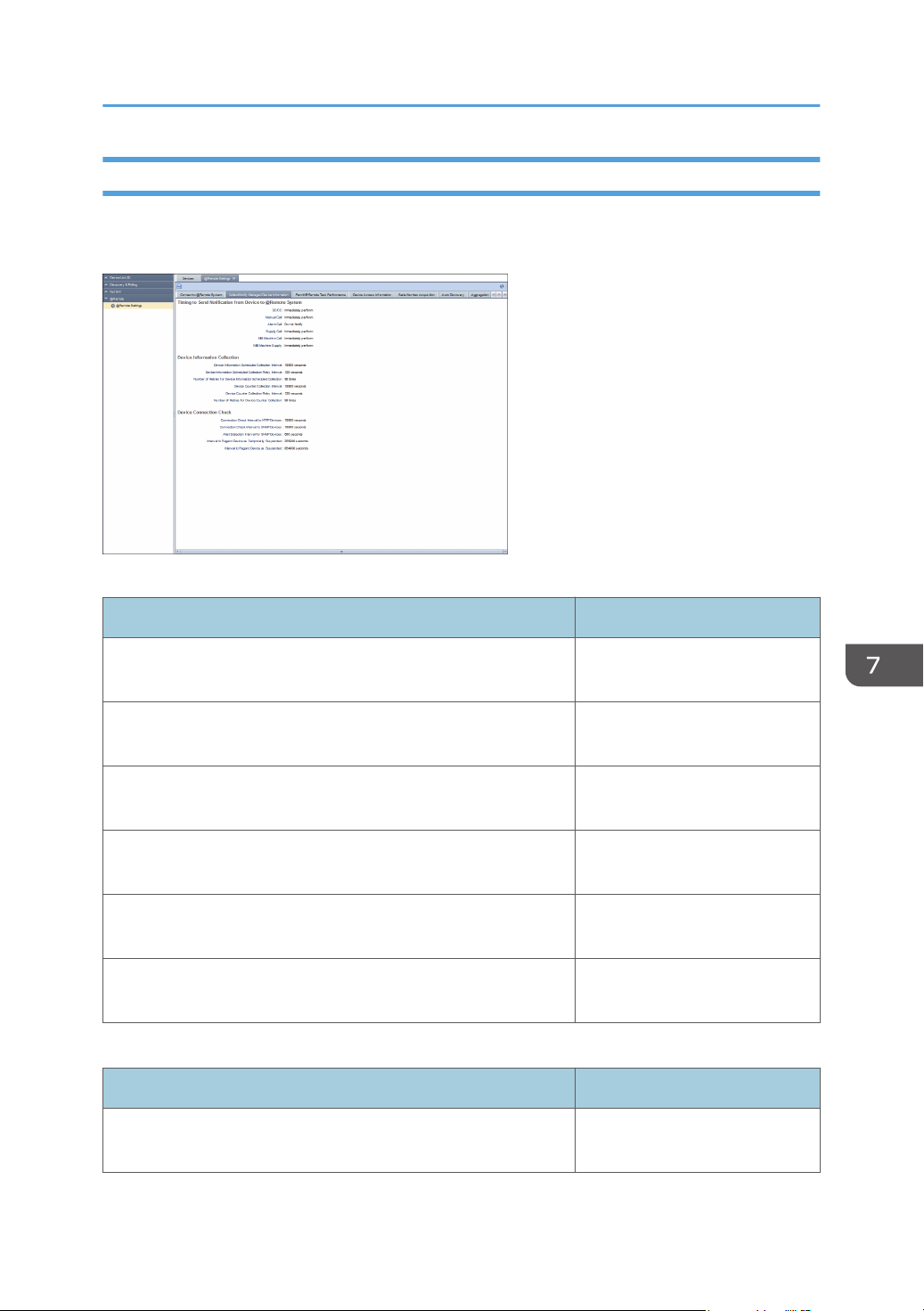
@Remote Settings
Collect/Notify Managed Device Information
You can check the communication status of the device connected to the network. To display the settings
screen, click [@Remote] - [@Remote Settings] and [Collect/Notify Managed Device Information] tab.
Timing to Send Notification from Device to @Remote System
Item Detail
SC/CC Indicates when service or
customer calls are notified.
Manual Call Displays the manual call
notification timing.
Alarm Call Displays the alarm call
notification timing.
Supply Call Displays the supply call
notification timing.
MIB Machine Call Indicates the timing of the device
call notification from MIB.
MIB Machine Supply Indicates the timing of the supply
call notification from MIB.
Device Information Collection
Item Detail
Device Information Scheduled Collection Interval Indicates intervals to retrieve the
device information.
89
Page 92
7. @Remote
Item Detail
Device Information Scheduled Collection Retry Interval Indicates retry intervals to
retrieve the device information if
it cannot be retrieved properly.
Number of Retries for Device Information Scheduled Collection Indicates how many times retries
are performed to retrieve the
device information if it cannot be
retrieved properly.
Device Counter Collection Interval Indicates intervals to retrieve the
device counter data.
Device Counter Collection Retry Interval Indicates the interval between
periodic retries in the case of
failing to retrieve the counter
date of the device.
Number of Retries for Device Counter Collection Indicates the number of times
between periodic retries in the
case of failing to retrieve the
counter date of the device.
Device Connection Check
Item Detail
Connection Check Interval to HTTP Devices Indicates intervals to check
whether a device supporting
HTTPS to retrieve data by the
HTTP protocol is connected.
Connection Check Interval to SNMP Devices Indicates intervals to check
whether a device supporting
SNMP to retrieve data by the
SNMP protocol is connected.
Alert Detection Interval for SNMP Devices Indicates an interval between
sending a warning alert from a
device supporting SNMP to
retrieve data by the SNMP
protocol.
90
Page 93
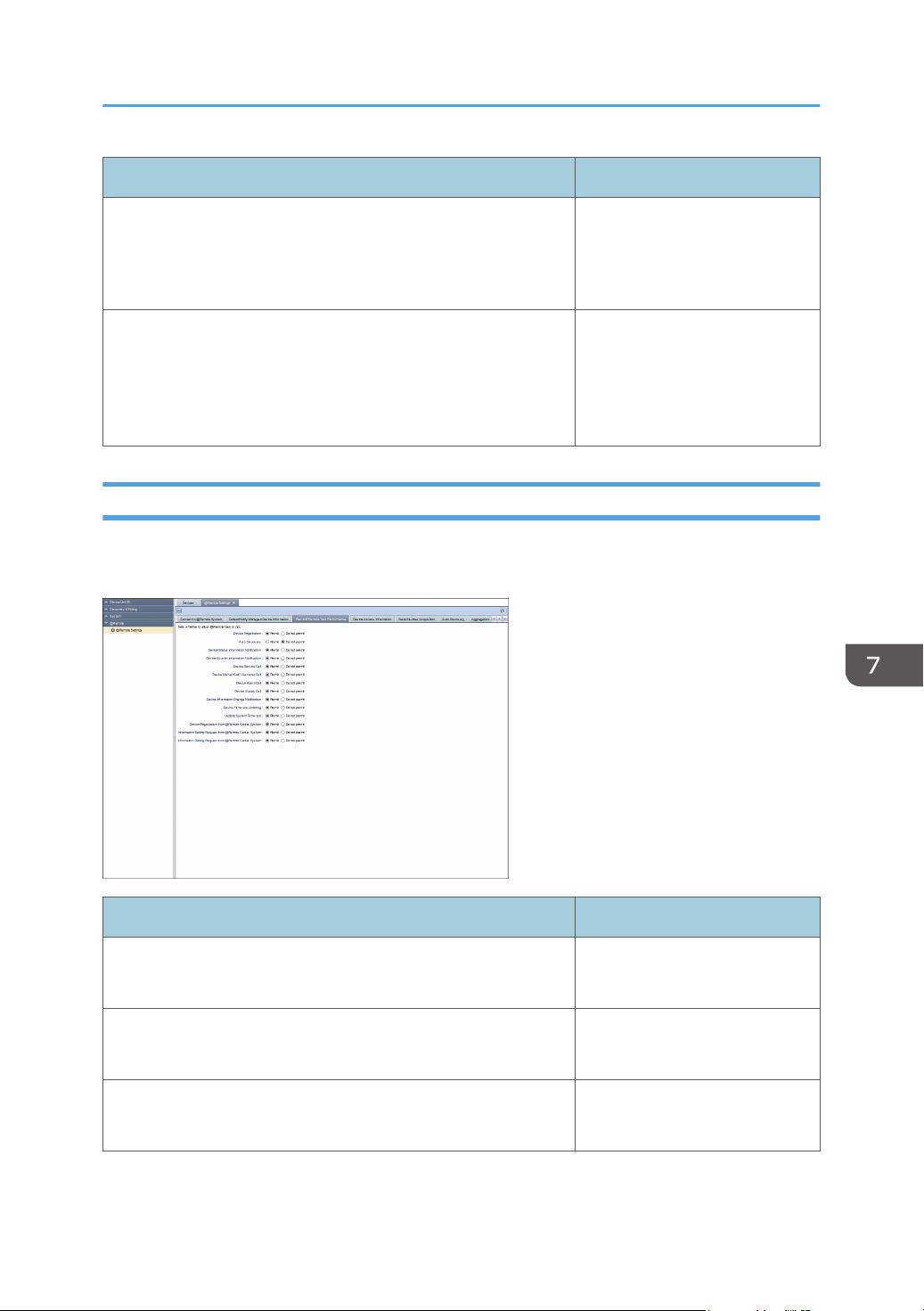
@Remote Settings
Item Detail
Interval to Regard Device as Temporarily Suspended Indicates how long it takes to
decide a network device is
offline temporarily after its
connection to the network is lost.
Interval to Regard Device as Suspended Indicates how long it takes to
decide that a network device is
offline for a long period of time
after its connection to the
network is lost.
Permit @Remote Task Performance
You can specify privileges for an @Remote task. To display the settings screen, click [@Remote] [@Remote Settings] and [Permit @Remote Task Performance] tab.
Item Detail
Device Registration Permit
Do not permit
Auto Discovery Permit
Do not permit
Device Status Information Notification Permit
Do not permit
91
Page 94
7. @Remote
Item Detail
Device Counter Information Notification Permit
Do not permit
Device Service Call Permit
Do not permit
Device Manual Call/ Customer Call Permit
Do not permit
Device Alarm Call Permit
Do not permit
Device Supply Call Permit
Do not permit
Device Information Change Notification Permit
Do not permit
Device Firmware Updating Permit
Do not permit
Update System Firmware Permit
Do not permit
Device Registration from @Remote Center System Permit
Do not permit
Information Setting Request from @Remote Center System Permit
Do not permit
Information Retrieval Request from @Remote Center System Permit
Do not permit
Device Access Information
You can display the device access settings and connection status. To display the settings screen, click
[@Remote] - [@Remote Settings] and [Device Access Information] tab.
92
Page 95
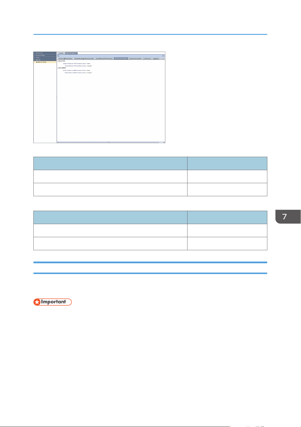
@Remote Settings
LAN (HTTP)
Item Detail
Number of Retries for HTTP Connection to Device Displays the number of retries.
Timeout Period for HTTP Connection to Device Indicates the time out period.
LAN (SNMP)
Item Detail
Number of Retries for SNMP Connection to Device Displays the number of retries.
Timeout Period for SNMP Connection to Device Indicates the time out period.
Serial Number Acquisition
You can specify settings to acquire the serial numbers of devices other than those of Ricoh products. To
display the settings screen, click [@Remote] - [@Remote Settings] and [Serial Number Acquisition] tab.
• You do not have the authority to perform this function.
93
Page 96
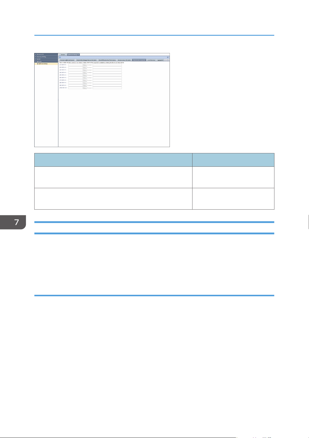
7. @Remote
Item Detail
OID (1-10) You do not have the authority to
perform this function.
Comment You do not have the authority to
perform this function.
Auto Discovery
This is the setting for collecting the network device information and sending it to the RS Center System
according to the specified schedule. To perform auto discovery, set auto discovery to [Permit] on [Permit
@Remote Task Performance] tab. To display the settings screen, click [@Remote] - [@Remote Settings]
and [Auto Discovery] tab.
Broadcast
Select the broadcast in the drop-down list box.
94
Page 97
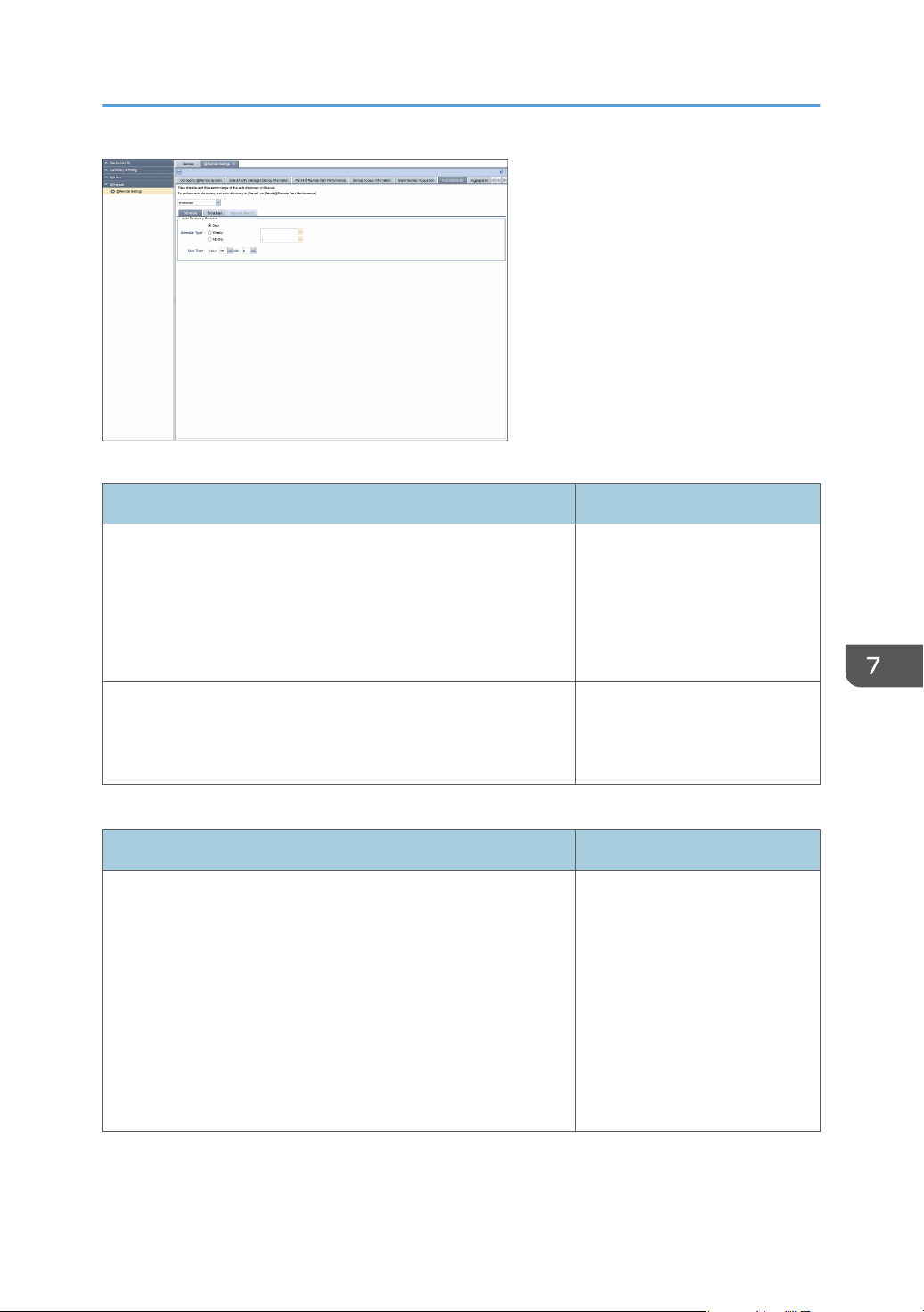
@Remote Settings
[Schedule] tab
Item Detail
Schedule Type Schedule type can be selected
from the following items.
• Daily
• Weekly
• Monthly
Start Time Setting start time
Hour: 0-23
Min: 00-59
[Broadcast] tab
Item Detail
[Discovery Range (Broadcast)] tab In the [Discovery Range
(Broadcast)] setting, you can
specify the following settings for
the local segment, subnet, and
IPv6 multicast (link-local):
• Subnet
• Subnet Mask
• Range Name
• Comment
95
Page 98
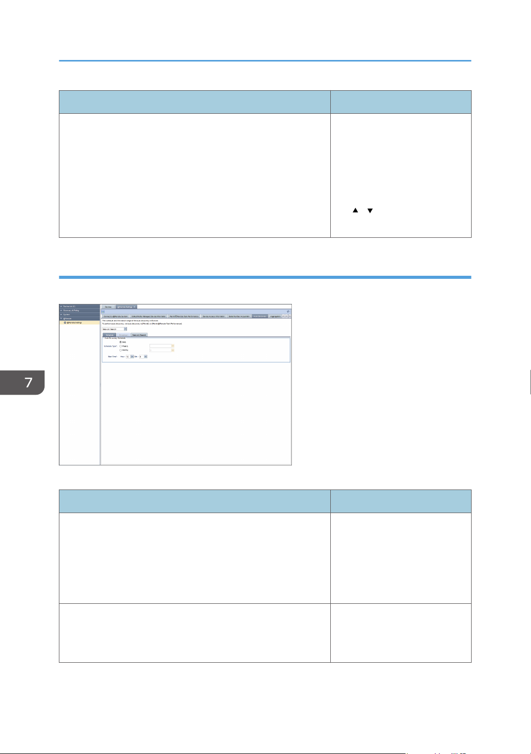
7. @Remote
Item Detail
[Access Accounts] tab Select an access account
suitable for communicating with
the devices that can be detected.
Change the account to be used
from [Not Assigned Accounts] to
[Assigned Account] by clicking
the [ ] [ ] button or by dragging
and dropping.
Network Search
Select the broadcast in the drop-down list box.
96
[Schedule] tab
Item Detail
Schedule Type Schedule type can be selected
from the following items.
• Daily
• Weekly
• Monthly
Start Time Setting start time
Hour: 0-23
Min: 00-59
Page 99
@Remote Settings
[Network Search] tab
Item Detail
[Discovery Range (Broadcast)] tab [Discovery Range (Network
Search)] can enter the following
item.
• Include/Exclude
• Range Type
- One Host Name
- One IP Address
- Specify IP Range
- IPv6 Address
• Host Name
• From
• To
• Subnet Mask
• Range Name
• Comment
[Access Accounts] tab Select the access accounts
suitable for communicating with
the devices in the discovery
range.
Change the account to be used
from [Not Assigned Accounts] to
[Assigned Account] by clicking
the [ ] [ ] button or by dragging
and dropping.
Migration
You can collectively manage multiple devices registered to the RC Gate by entering the RC Gate ID. To
display the settings screen, click [@Remote] - [@Remote Settings] and [Migration] tab.
• You do not have the authority to perform this function.
97
Page 100
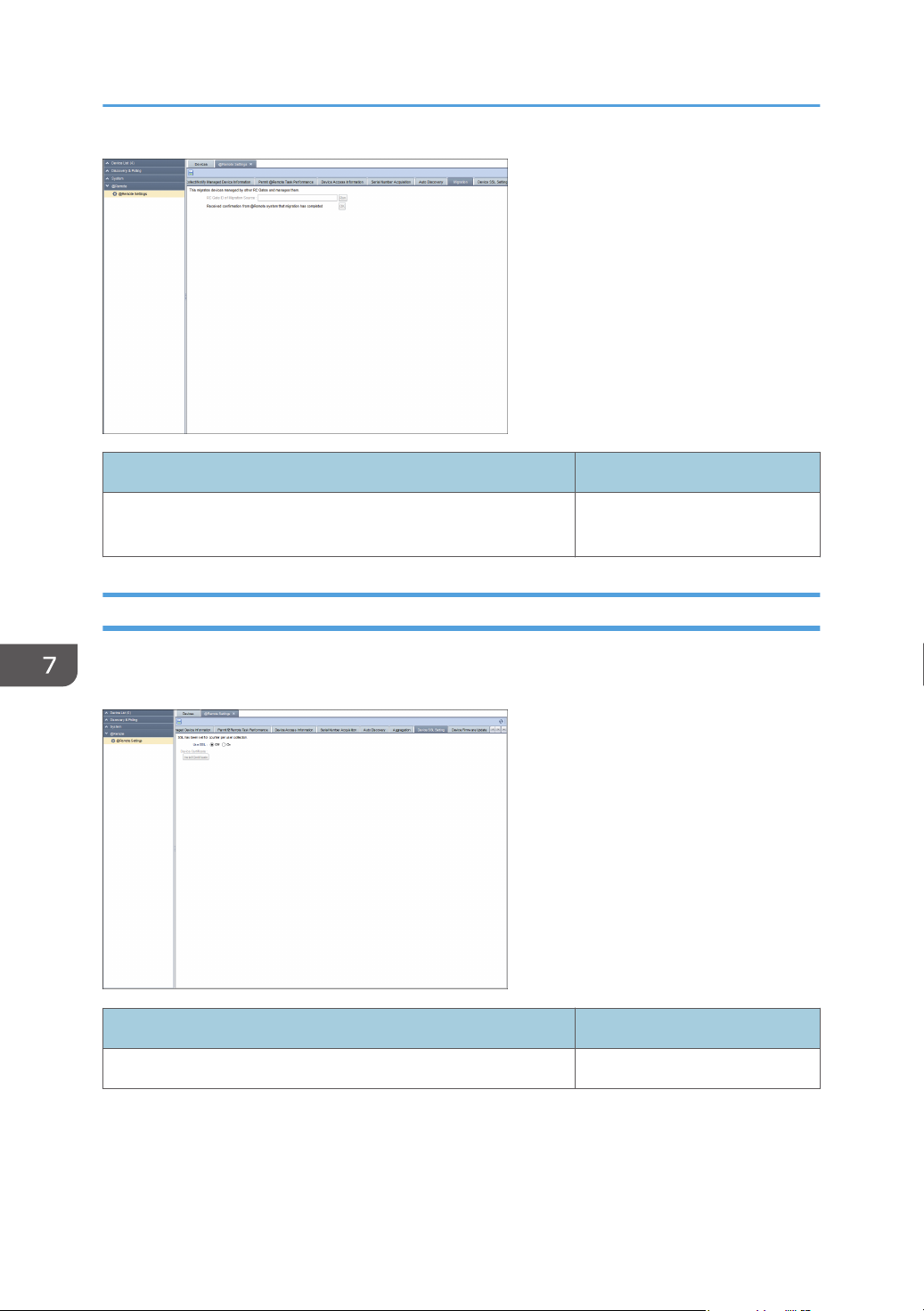
7. @Remote
Item Detail
RC Gate ID of Migration Source You do not have the authority to
perform this function.
Device SSL Setting
You can install a certificate for SSL communication to collect the counter log of each user. To display the
settings screen, click [@Remote] - [@Remote Settings] and [Device SSL Setting] tab.
Item Detail
Use SSL To use SSL, select [On].
98
 Loading...