

Ricoh 7650 Service Manual
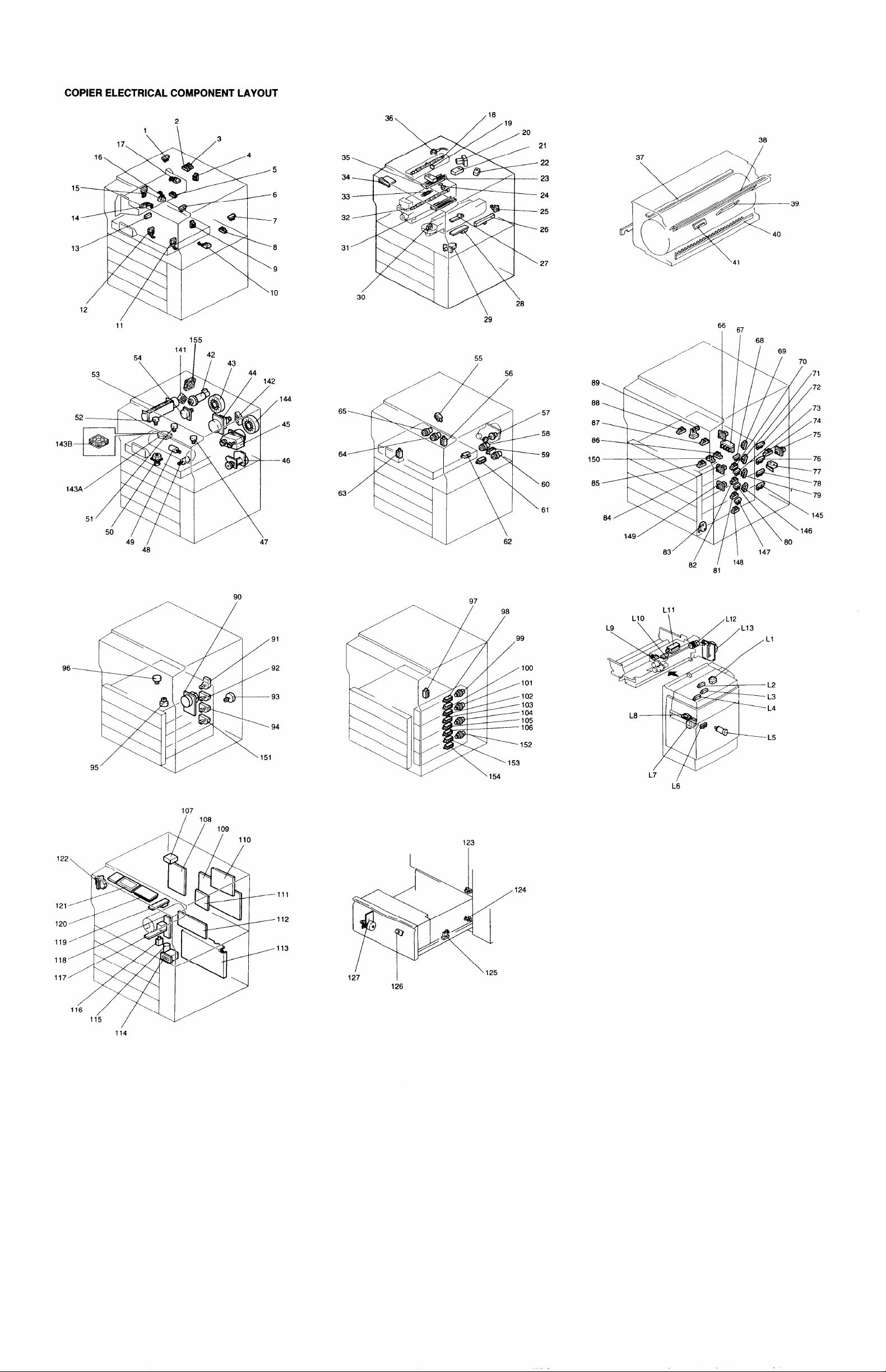
COPIER ELECTRICAL COMPONENT LAYOUT
.
38
35
34
11
155
33
32
31
66 67
1
55
– 39
48
90
107
108
/
/ 109
123
97
9
100
101
102
103
104
105
106
152
I
83 ‘
//1147
L11
LIO
\
L7
/
L6
/L12
114
111
112
113
124
1
126
Rev. 9/15/96
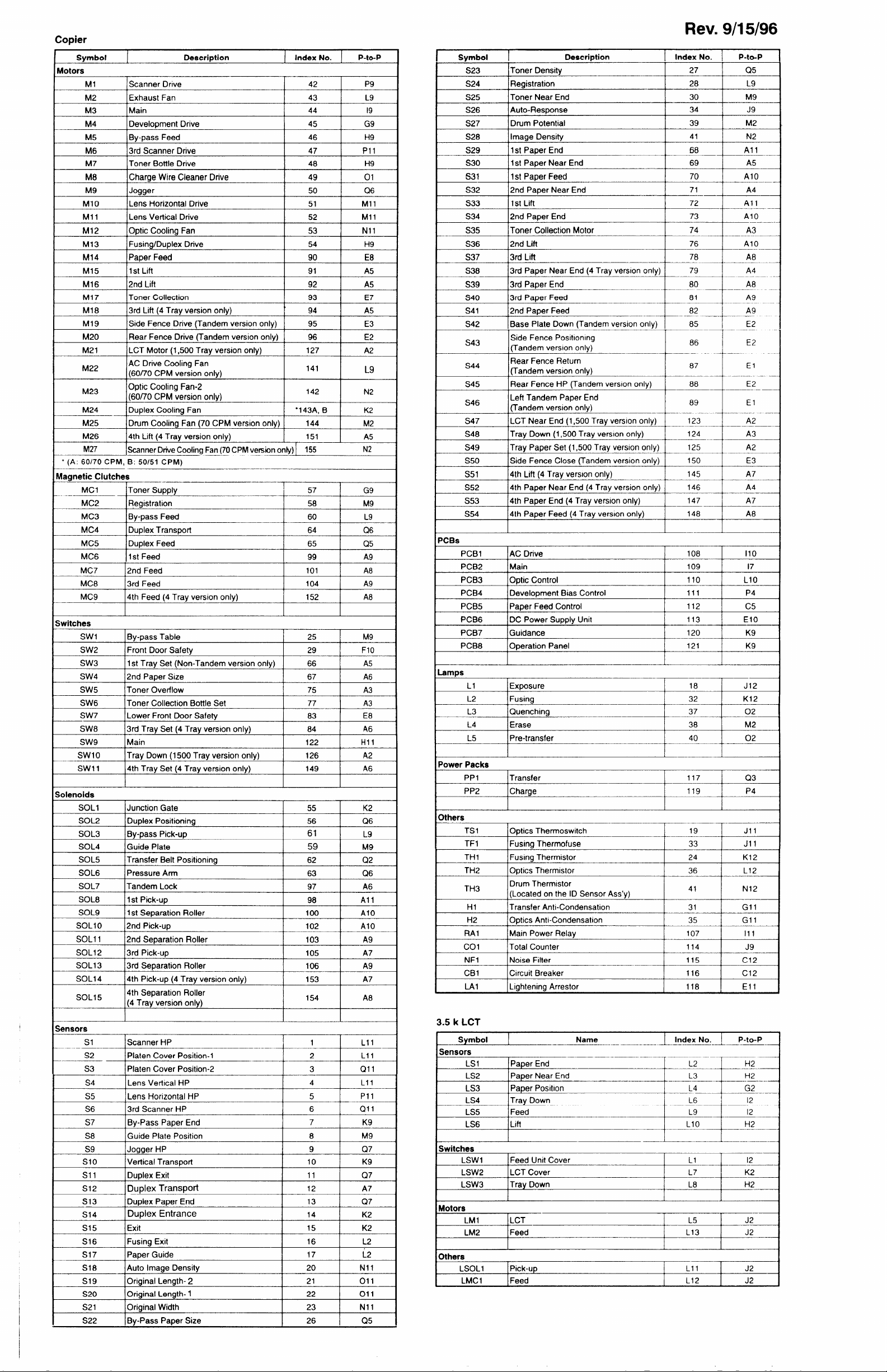
Svmbol DescrirMion Index No. P-to-P
Motors
Ml
—
M2 Exhaust Fan 43
M3 lMain
M4 lDeveioDment Drive
M5 By-pass Feed 46 H9
M6 3rd
M7
Scanner Drive
42
44
I
I 45 I G9
Scanner Drive 47 Pll S29
lToner Bottle Drive
48
I
M’ Charge Wire Cleaner Drive 49
M9
M1O
Mll Lens Vertical Drive
Jogger
Lens Horizontal Drive
50
51 Mll
52 Mll
P9
L9
19
I
H9
I
01
Q6
53 Nll
M13 Fusing/Duplex Drive 54 H9 S36 2nd Lift 76
90
I
M15
M16
M17 Toner Collection
M18 13rd Lift (4 Trav version onlv)
M19 lSide Fence Drive (Tandem version onlv)
M20 Rear Fence Drive (Tandem version only)
M21 LCT Motor (1 ,500 Tray version only)
M22
M23
M24 Duplex Cooling Fan
M25
M26 14th Lift (4 Trav version onlv)
M27 \S.cannerDrive Cooling Fan (70 CPMversion onty) I 155 N2
* (A: 60/70 CPM, B: 50/51 CPM)
]1st Lift
2nd
Lift
91 A5
92 A5
93
94
t
I 95 I E3
96 E2
127
AC Drive Cooling Fan
(60/70 CPM version onlv)
Optic Cooling Fan-2
(60/70 CPM version only)
/Drum Caolina Fan (70 CPM version onlv) I 144
I
I
141
142
●143A, B
151
I
I
I
M2
I
I A5
E8
E7
A5
A2
L9
N2
K2
IAaanetic Clutches
MC1
.-
MC2
MC3
MC4 lDuciex TransDort
MC5 Duplex Feed
MC6 1st Feed
MC7 12nd Feed
MC8
MC9
Toner Supply
Registration
BV-DaSS Feed
60 L9
I 64 I (26
65
99
I 101 I A8
3rd Feed 104
4th Feed (4 Tray version
Ot?lY)
152
57 G9
58 M9
Q5
A9
A9
A8
jwitches
Swl IBv-Dass Table
SW2
SW3 1st Trav Set (Non-Tandem version onlv)
SW4 12nd PaDer Size
SW5 lToner Overflow
SW6 Toner Collection Bottle Set
SW7 Lower Front Door Safetv
SW8 3rd Tray Set (4 Tray version only)
SW9 Main
Swlo
Swl 1
)olenoids
Front Door Safety
lTrav Down (1500 Trav version onlv) I 126
Trav Set (4 Trav version onlv)
14th
SOL1 Junction Gate
SOL2 Duplex Positioning
SOL3 By-pass Pick-up
SOL4
SOL5 Transfer Belt Positioning
SOL6 Pressure Arm
SOL7
SOL8 ]1st Pick-up
SOL9
SOL1O 2nd pick-uD
Guide Plate 59 M9
lTandem Lack
1st
Separation Roller
SOLI 1 12nd Sec)aration Roller
SOL12
SOL13
SOL14 4th Pick-up (4 Tray version only)
SOL15
3rd Pick-up
3rd Separation Roller
4th Separation Roller
(4 Tray version only)
1
I 25 I M9
29
66 A5
I 67 I
F1O
A6
I 75 I A3
77 A3
83
84 A6
122
149
I
55
56 Q6
61
62
63 Q6
E8
Hll
A2
I
A6
I
K2
L9
Q2
I 97 I /46
98 All
I
100
102 AlO
AlO
I 103 I A9
105 A7
106 A9
153 A7
154 A8
I
I
Svmbol
S23
S24 IRegistration
S25
S26
S27 Drum Potential 39
S28
I
lToner Densitv
Toner Near End 30 M9
Auto-Response 34 J9
IImaae Densitv
]1st Paper End
S30 1st Paper Near End 69
631 1st
S32
S33 1st Lift
S34 2nd Paper End
S35 ]Toner Collection Motor
S37
S38 \3rd PaDer Near End (4 Trav version onlv) I
S39 3rd Paper End
S40
S41 2nd Paper Feed
S42
S43
S44
S45
S46
S47
S48 Tray Down (1 ,500 Tray version only)
S49
S50
S51
S52
S53 14th
S54 14th PaDer Feed (4 Trav version onlv) /
PaDer Feed 70 AlO
12nd PaDer Near End
3rd Lift 78 A8M14 lPaDer Feed
3rd PaDer Feed
Base Plate Down (Tandem version only)
Side Fence Positioning
(Tandem
Rear Fence Return
(Tandem version only)
Rear Fence HP (Tandem version only) 88
Left Tandem Paper End
(Tandem version
LCT Near End (1 ,500 Tray version only)
Tray Paper Set (1,500 Tray version only) 125 AZ -
lSide Fence Close (Tandem version onlv) I
4th Lift (4 Tray version only) 145 A7
4th Paper Near End (4 Tray version only) 146 A4
PaDer End [4 Trav version onlv)
~CBs
PCB1 IAC Drive 108 110
PCB2
PCB3
PCB4
PCB5
PCB6 DC Power Supply Unit 113
PCB7 Guidance 120 K9
PCB8
L1
L2 IFusina
L3
L4
L5 lPre-transfer
IMain
10c4icControl
IDevelopment Bias Control
Paper Feed Control 112
moderation Panel
lExDosure
Quenching
Erase
‘ower Packs
PP1
PP2
Transfer 117
lCharae
)thers
TS 1
—
TF1
TH 1
TH2
TH3
H1
H2 10dics Anti-Condensation
NF1
CB1
—T---
I
Cbtics Thermoswitch
I
IFusinq Thermofuse
IFusma Thermistor
10rMics Thermwtor
Drum Thermistor
(Located on the ID Sensor Ass’y)
lTransfer Anti-Condensation
INoise Filter
lCircuit Breaker
LAl ILightening Arrestor 118
Description
version only)
onlv)
I Index No. \ P-to-P
27
I
28
I
I I
‘8-—u–
71
I
+H-+”
74
I
——
79
–t--::- -+---::
-----+-”-::--”t---_:;
-——
“+~
86 E2
87 El
89
I
123
124 A3
150
147 I
I
148
109
I
110
I
111
I
121
I
18
I
32
I
40
I
—
119
I
19
I
33
I
24
I
I 36 I L12
41
I
31
I
I 35 I Gll
115
I
116
I
Q5
I
L9
I
M2
N2
A5
+--
A4
I
A3M12 Optic Cooling Fan
I
AlO
+
A4
I
—
7
——
I
I
A7
A8
I
I
L1O
I
P4
I
C5
E1O
K9
I
J12
I
K12
I
I 02
Q3
P4
I
Jll
I
Jll
I
K12
I
N12
I
I Gll
I C12
I C12
Ell
E2 ‘-
El
A2
E3
17
‘1-------- -
.-
A
—
;ensors
S1
S2 Platen Cover Position-1
S3
S4
S5
S6 3rd Scanner HP
S7 By-Pass Paper End 7 K9
S8 Guide Plate Position
S9 lJoaaer HP
Slo Iverlical TransDort 10
Sll
S12 Duplex Transport
S13 Duplex Paper End
S14
S15 I Exit
S16 Fusing Exit 16
S17 Paper Guide 17
S18 Auto Imaqe Density
S19
S20
1
S21 10riainal Width
S22
\Scanner HP
Platen Cover Position-2
ILens Vertical HP
I
-----t
I
Lens Horizontal HP 5
I
Duplex Exit
Duplex Entrance
I
10riainal Lenqth- 2
10riainal Lenath- 1
I
I
I 23 I Nll
IBy-Pass Paper Size
1 L11
2 L11
3 Qll
4
L11
I
Pll
6
8
9
11
12 A7
13
14
15
20 N11
21
22
26
QI 1
M9
Q7
I
K9
I
Q7
Q7
K2
K2
I
I 011
I 011
Q5
I
L2
L2
Svmbol I Name
Sensors
LS1 IPaDer End
LS2
LS3 Paper Posdlon L4
LS4 Tray Down
LS5 Feed
LS6
Paper Near End
Lift
Switches
LSW1
LSW2 LCT Cover L7 K2
LSW3
Feed Unit Cover
Tray Down
Motors
LM1 ILCT
LM2
Feed
others
LSOL1
LMC1
IPick-utI
]Feed L12 J2
I Index No. I P-to-P
1 L2
— ————
+
.rm2 —-.
I-3 HZ
‘G2
L6
L9
“0 +--
L1 12 -
L8
I L5 r J2-
L13
L;- J2
12
12
H2
J2

 Loading...