

Page 1

© 2007 Ricoh Americas Corporation
5 Dedrick Place
West Caldwell, NJ 07006
A
ugust 2007
338550-003C
User’s Guide
Page 2

© 2007 Ricoh Americas Corporation. All rights reserved.
No part of this document may be reproduced without the expressed permission of Ricoh
Americas Corporation.
The material in this document is for informational purposes and is subject to change
without notice. Ricoh Americas Corporation assumes no responsibility for errors or
omissions in this document. No liability is assumed for any damages resulting from the
use of the information it contains.
TRADEMARK
Adobe and Postscript are registered trademarks of Adobe Systems Incorporated. PCL
is the trademark of Hewlett Packard. Ethernet is a trademark of Xerox Corporation.
Windows XP is a trademark of Microsoft Corporation. Digital Document Publisher and
DDP and its associated logo mark are the trademarks of Ricoh Americas Corporation.
Ricoh and the Ricoh trademark are registered trademarks of Ricoh, Ltd. All rights
reserved.
All other terms and product names may be trademarks or register ed trad emarks of their
respective owners and are hereby acknowledged.
NOTICE TO USER
In an effort to meet the demands of a rapidly changing technology, the manufacturer is
continually developing new feat ures and functions to meet changing printing or printer
needs. Please be sure to consult all manual updates or addenda when using this
product’s documentation.
This document contains TrueType fonts from Monotype Imaging Inc. Reproduction of
these fonts is prohibited.
The software embedded in this product is based in part on the work of Independent
JPEG Group.
The software embedded in this product uses so ftware by CMU. Copyright 1988, 1989 by
Carnegie Mellon University. All rights reserved.
The software embedded in this product uses software by Intermate A/S. Copyright 2005.
All rights reserved.
Permission to use, copy, modify, distribute and sell this software and its documentation
for any purpose and without fee is hereby granted, provided that the above copyright
notice appears in all copies and that both the copyright notice and permission notice
appear in supporting documentation, and the name of CMU not be used in advertising
or publicity pertaining to distribution of the software without specific written prior
permission.
The software embedded in this product uses the software by Sam Leffler and Silicon
Graphics.
Copyright (c) 1988-1997 Sam Leffler
Copyright (c) 1991-1997 Silicon Graphics, Inc
Permission to use, copy, modify, distribute and sell this software and its documentation
for any purpose and without fee is hereby granted, provided that the above copyright
notice appear in all copies of the software and related docume ntation, and (ii) the names
of Sam Leffler and Silicon Graphics may not be used in advertising or publicity pertaining
to distribution of the software without specific, written prior permission of Sam Leffler and
Silicon Graphics.
Page 3

Our company, as a partner in the Energy Star Program, considers that this product
satisfies the appropriate standard covered in this program.
NOTE:
The 70 and 92 PPM printers come with the power management mode enabled and
will go into a “Sleep” mode after 7 minutes (70 PPM) or 15 minutes (92 PPM) if there
is no printing or communications with the printer.
These are default settings and should remain in these conditions to get the energy
saving benefits of Energy Star.
Page 4

Revisions
Revision Page No. (Contents) Date
A Original Release - ECO-1772 February 2006
B
Page B-2: Corrected Controller processor speed to 800
MHz (Egret 3R);
February 2007
Add rev history page, copyright page;
Page 5-1, add "Network Problems" to bulleted list
C
Page i, Updated Energy Star page to add Power
March 2007
Management feature.
Pages 4-9 and 4-31, added RC number to developer p/n
Page 6-2, updated Web Site layout sheet to include IPDS
i
Page 5

Table of Contents
Introduction
About This Manual. . . . . . . . . . . . . . . . . . . . . . . . . . . . . . . . . . . . . . . . . . . . . . . . . . . . . . . . . . vi
Audience . . . . . . . . . . . . . . . . . . . . . . . . . . . . . . . . . . . . . . . . . . . . . . . . . . . . . . . . . . . . . .
Manual Conventions . . . . . . . . . . . . . . . . . . . . . . . . . . . . . . . . . . . . . . . . . . . . . . . . . . . .
For More Information . . . . . . . . . . . . . . . . . . . . . . . . . . . . . . . . . . . . . . . . . . . . . . . . . . . .
Chapter 1. Printer Overview
What This Chapter Provides . . . . . . . . . . . . . . . . . . . . . . . . . . . . . . . . . . . . . . . . . . . . . . . . . . . 1-1
Printer Features . . . . . . . . . . . . . . . . . . . . . . . . . . . . . . . . . . . . . . . . . . . . . . . . . . . . . . . . . . . . . 1-2
I/O Configurations . . . . . . . . . . . . . . . . . . . . . . . . . . . . . . . . . . . . . . . . . . . . . . . . . . . . . . . . . . 1-3
Operator Control Panel . . . . . . . . . . . . . . . . . . . . . . . . . . . . . . . . . . . . . . . . . . . . . . . . . . . . . . . 1-4
External View of the Printer . . . . . . . . . . . . . . . . . . . . . . . . . . . . . . . . . . . . . . . . . . . . . . . . . . . 1-5
Internal View of the Printer. . . . . . . . . . . . . . . . . . . . . . . . . . . . . . . . . . . . . . . . . . . . . . . . . . . . 1-6
Chapter 2. Operator Control Panel
What This Chapter Provides . . . . . . . . . . . . . . . . . . . . . . . . . . . . . . . . . . . . . . . . . . . . . . . . . . . 2-1
OCP Description . . . . . . . . . . . . . . . . . . . . . . . . . . . . . . . . . . . . . . . . . . . . . . . . . . . . . . . . . . . . 2-2
Menu Structure . . . . . . . . . . . . . . . . . . . . . . . . . . . . . . . . . . . . . . . . . . . . . . . . . . . . . . . . . . . . . 2-3
Using the Menu Screens . . . . . . . . . . . . . . . . . . . . . . . . . . . . . . . . . . . . . . . . . . . . . . . . . . . . . . 2-9
Main Menu . . . . . . . . . . . . . . . . . . . . . . . . . . . . . . . . . . . . . . . . . . . . . . . . . . . . . . . . . . . 2-10
Information . . . . . . . . . . . . . . . . . . . . . . . . . . . . . . . . . . . . . . . . . . . . . . . . . . . . . . . . . . . 2-11
Printer Menu . . . . . . . . . . . . . . . . . . . . . . . . . . . . . . . . . . . . . . . . . . . . . . . . . . . . . . . . . . 2-12
Setup Menu . . . . . . . . . . . . . . . . . . . . . . . . . . . . . . . . . . . . . . . . . . . . . . . . . . . . . . . . . . . 2-15
Reports Menu . . . . . . . . . . . . . . . . . . . . . . . . . . . . . . . . . . . . . . . . . . . . . . . . . . . . . . . . . 2-17
Finisher Menu for the Container Stacker . . . . . . . . . . . . . . . . . . . . . . . . . . . . . . . . . . . . 2-18
Jobs Menu . . . . . . . . . . . . . . . . . . . . . . . . . . . . . . . . . . . . . . . . . . . . . . . . . . . . . . . . . . . . 2-19
Passwords . . . . . . . . . . . . . . . . . . . . . . . . . . . . . . . . . . . . . . . . . . . . . . . . . . . . . . . . . . . . . . . . 2-20
vi
.vii
vii
Chapter 3. Paper Handling
What This Chapter Provides . . . . . . . . . . . . . . . . . . . . . . . . . . . . . . . . . . . . . . . . . . . . . . . . . . . 3-1
Paper . . . . . . . . . . . . . . . . . . . . . . . . . . . . . . . . . . . . . . . . . . . . . . . . . . . . . . . . . . . . . . . . . . . . . 3-2
Paper Weights . . . . . . . . . . . . . . . . . . . . . . . . . . . . . . . . . . . . . . . . . . . . . . . . . . . . . . . . . . 3-2
Paper Color . . . . . . . . . . . . . . . . . . . . . . . . . . . . . . . . . . . . . . . . . . . . . . . . . . . . . . . . . . . . 3-2
Unacceptable Paper . . . . . . . . . . . . . . . . . . . . . . . . . . . . . . . . . . . . . . . . . . . . . . . . . . . . . . 3-2
Storing Paper . . . . . . . . . . . . . . . . . . . . . . . . . . . . . . . . . . . . . . . . . . . . . . . . . . . . . . . . . . . 3-3
Paper Sizes, Paper Types, and Printer Input Trays. . . . . . . . . . . . . . . . . . . . . . . . . . . . . . . . . . 3-4
Loading Paper . . . . . . . . . . . . . . . . . . . . . . . . . . . . . . . . . . . . . . . . . . . . . . . . . . . . . . . . . . . . . . 3-5
Loading Paper in Tray 1 . . . . . . . . . . . . . . . . . . . . . . . . . . . . . . . . . . . . . . . . . . . . . . . . . . 3-5
Table of Contents ii
Page 6

Loading Paper in Tray 2 or 3 . . . . . . . . . . . . . . . . . . . . . . . . . . . . . . . . . . . . . . . . . . . . . . . 3-7
Loading Paper into the MBT . . . . . . . . . . . . . . . . . . . . . . . . . . . . . . . . . . . . . . . . . . . . . . . 3-9
Loading Paper into the HCF . . . . . . . . . . . . . . . . . . . . . . . . . . . . . . . . . . . . . . . . . . . . . . 3-11
Loading Special Media . . . . . . . . . . . . . . . . . . . . . . . . . . . . . . . . . . . . . . . . . . . . . . . . . . 3-12
Pre-punched Paper . . . . . . . . . . . . . . . . . . . . . . . . . . . . . . . . . . . . . . . . . . . . . . . . . . 3-12
Loading Pre-printed Paper . . . . . . . . . . . . . . . . . . . . . . . . . . . . . . . . . . . . . . . . . . . . 3-14
Loading Tab Stock . . . . . . . . . . . . . . . . . . . . . . . . . . . . . . . . . . . . . . . . . . . . . . . . . . 3-15
Setting the Custom Paper Size Values . . . . . . . . . . . . . . . . . . . . . . . . . . . . . . . . . . . . . . . . . . 3-16
Setting the Tray Adjust Values. . . . . . . . . . . . . . . . . . . . . . . . . . . . . . . . . . . . . . . . . . . . . . . . 3-16
Setting the Default Paper Source . . . . . . . . . . . . . . . . . . . . . . . . . . . . . . . . . . . . . . . . . . . . . . 3-17
Setting the Paper Type . . . . . . . . . . . . . . . . . . . . . . . . . . . . . . . . . . . . . . . . . . . . . . . . . . . . . . 3-17
Setting the Paper Weight. . . . . . . . . . . . . . . . . . . . . . . . . . . . . . . . . . . . . . . . . . . . . . . . . . . . . 3-17
Setting the Paper Color . . . . . . . . . . . . . . . . . . . . . . . . . . . . . . . . . . . . . . . . . . . . . . . . . . . . . . 3-17
Ordered Sets . . . . . . . . . . . . . . . . . . . . . . . . . . . . . . . . . . . . . . . . . . . . . . . . . . . . . . . . . . . . . . 3-18
Define the Ordered Sets . . . . . . . . . . . . . . . . . . . . . . . . . . . . . . . . . . . . . . . . . . . . . . . . . . 3-19
Chapter 4. Care and Maintenance
What This Chapter Provides . . . . . . . . . . . . . . . . . . . . . . . . . . . . . . . . . . . . . . . . . . . . . . . . . . . 4-1
Replacing Consumables . . . . . . . . . . . . . . . . . . . . . . . . . . . . . . . . . . . . . . . . . . . . . . . . . . . . . . 4-2
Adding Toner . . . . . . . . . . . . . . . . . . . . . . . . . . . . . . . . . . . . . . . . . . . . . . . . . . . . . . . . . . . 4-3
Replacing the Toner Collector Bottle . . . . . . . . . . . . . . . . . . . . . . . . . . . . . . . . . . . . . . . . 4-6
Replacing the Developer Mix . . . . . . . . . . . . . . . . . . . . . . . . . . . . . . . . . . . . . . . . . . . . . . 4-7
Exhausting the Developer Mix . . . . . . . . . . . . . . . . . . . . . . . . . . . . . . . . . . . . . . . . . . 4-7
Supplying the Developer Mix . . . . . . . . . . . . . . . . . . . . . . . . . . . . . . . . . . . . . . . . . . . 4-9
Replacing the Drum Unit . . . . . . . . . . . . . . . . . . . . . . . . . . . . . . . . . . . . . . . . . . . . . . . . . 4-12
Replacing the Fuser Cleaning Web . . . . . . . . . . . . . . . . . . . . . . . . . . . . . . . . . . . . . . . . . 4-15
Replacing Staples . . . . . . . . . . . . . . . . . . . . . . . . . . . . . . . . . . . . . . . . . . . . . . . . . . . . . . 4-17
Clearing Paper Jams . . . . . . . . . . . . . . . . . . . . . . . . . . . . . . . . . . . . . . . . . . . . . . . . . . . . . . . . 4-18
Vertical Path (IS) Cover . . . . . . . . . . . . . . . . . . . . . . . . . . . . . . . . . . . . . . . . . . . . . . . . . 4-18
Switch Back Area . . . . . . . . . . . . . . . . . . . . . . . . . . . . . . . . . . . . . . . . . . . . . . . . . . . . . . 4-19
Paper Feed Block Area . . . . . . . . . . . . . . . . . . . . . . . . . . . . . . . . . . . . . . . . . . . . . . . . . . 4-21
Trays 1, 2, and 3 . . . . . . . . . . . . . . . . . . . . . . . . . . . . . . . . . . . . . . . . . . . . . . . . . . . . . . . 4-23
Tray 1 . . . . . . . . . . . . . . . . . . . . . . . . . . . . . . . . . . . . . . . . . . . . . . . . . . . . . . . . . . . . 4-23
Tray 2 or 3 . . . . . . . . . . . . . . . . . . . . . . . . . . . . . . . . . . . . . . . . . . . . . . . . . . . . . . . . . 4-23
Multi-bypass Tray . . . . . . . . . . . . . . . . . . . . . . . . . . . . . . . . . . . . . . . . . . . . . . . . . . . . . . 4-24
High Capacity Feeder . . . . . . . . . . . . . . . . . . . . . . . . . . . . . . . . . . . . . . . . . . . . . . . . . . . 4-24
Tab Stock Jam Recovery . . . . . . . . . . . . . . . . . . . . . . . . . . . . . . . . . . . . . . . . . . . . . . . . . 4-25
Cleaning the Printer. . . . . . . . . . . . . . . . . . . . . . . . . . . . . . . . . . . . . . . . . . . . . . . . . . . . . . . . . 4-26
Cleaning the Printer Covers . . . . . . . . . . . . . . . . . . . . . . . . . . . . . . . . . . . . . . . . . . . . . . . 4-26
Cleaning the Inside of the Printer . . . . . . . . . . . . . . . . . . . . . . . . . . . . . . . . . . . . . . . . . . 4-27
Cleaning Trays 1, 2 and 3, the MBT, and HCF . . . . . . . . . . . . . . . . . . . . . . . . . . . . . . . . 4-27
Cleaning the Toner Bottle Joint . . . . . . . . . . . . . . . . . . . . . . . . . . . . . . . . . . . . . . . . . . . . 4-28
Cleaning the Conveyance Belt Area . . . . . . . . . . . . . . . . . . . . . . . . . . . . . . . . . . . . . . . . 4-28
Cleaning the Toner Collector Bottle Area . . . . . . . . . . . . . . . . . . . . . . . . . . . . . . . . . . . . 4-29
Handling and Storing Supplies and Consumables . . . . . . . . . . . . . . . . . . . . . . . . . . . . . . . . . 4-30
iii Table of Contents
Page 7

Paper . . . . . . . . . . . . . . . . . . . . . . . . . . . . . . . . . . . . . . . . . . . . . . . . . . . . . . . . . . . . . . . . 4-30
When Loading . . . . . . . . . . . . . . . . . . . . . . . . . . . . . . . . . . . . . . . . . . . . . . . . . . . . . . 4-30
When Storing . . . . . . . . . . . . . . . . . . . . . . . . . . . . . . . . . . . . . . . . . . . . . . . . . . . . . . 4-30
When Paper Jams Frequently Occur . . . . . . . . . . . . . . . . . . . . . . . . . . . . . . . . . . . . . 4-30
Toner and Developer . . . . . . . . . . . . . . . . . . . . . . . . . . . . . . . . . . . . . . . . . . . . . . . . . . . . 4-31
When Purchasing . . . . . . . . . . . . . . . . . . . . . . . . . . . . . . . . . . . . . . . . . . . . . . . . . . . 4-31
Chapter 5. Troubleshooting
What This Chapter Provides . . . . . . . . . . . . . . . . . . . . . . . . . . . . . . . . . . . . . . . . . . . . . . . . . . . 5-1
Guidelines Flowchart . . . . . . . . . . . . . . . . . . . . . . . . . . . . . . . . . . . . . . . . . . . . . . . . . . . . . . . . 5-2
Basic Troubleshooting Tips . . . . . . . . . . . . . . . . . . . . . . . . . . . . . . . . . . . . . . . . . . . . . . . . . . . 5-3
General Printing Problems . . . . . . . . . . . . . . . . . . . . . . . . . . . . . . . . . . . . . . . . . . . . . . . . . . . . 5-4
Print Quality Problems . . . . . . . . . . . . . . . . . . . . . . . . . . . . . . . . . . . . . . . . . . . . . . . . . . . . . . . 5-5
Duplex Printing Problems. . . . . . . . . . . . . . . . . . . . . . . . . . . . . . . . . . . . . . . . . . . . . . . . . . . . . 5-6
Printing Notes . . . . . . . . . . . . . . . . . . . . . . . . . . . . . . . . . . . . . . . . . . . . . . . . . . . . . . . . . . . . . . 5-7
OCP Display Messages. . . . . . . . . . . . . . . . . . . . . . . . . . . . . . . . . . . . . . . . . . . . . . . . . . . . . . . 5-8
Printer Limitations . . . . . . . . . . . . . . . . . . . . . . . . . . . . . . . . . . . . . . . . . . . . . . . . . . . . . . . . . 5-16
Network Problems. . . . . . . . . . . . . . . . . . . . . . . . . . . . . . . . . . . . . . . . . . . . . . . . . . . . . . . . . . 5-18
Chapter 6. Web Utilities
Features. . . . . . . . . . . . . . . . . . . . . . . . . . . . . . . . . . . . . . . . . . . . . . . . . . . . . . . . . . . . . . . . . . . 6-1
Web Utilities Access. . . . . . . . . . . . . . . . . . . . . . . . . . . . . . . . . . . . . . . . . . . . . . . . . . . . . . . . . 6 -1
Web Site Layout . . . . . . . . . . . . . . . . . . . . . . . . . . . . . . . . . . . . . . . . . . . . . . . . . . . . . . . . . . . . 6-2
Using the Web Utilities. . . . . . . . . . . . . . . . . . . . . . . . . . . . . . . . . . . . . . . . . . . . . . . . . . . . . . . 6-3
Appendix A. Safety Information
General . . . . . . . . . . . . . . . . . . . . . . . . . . . . . . . . . . . . . . . . . . . . . . . . . . . . . . . . . . . . . . . . . . .A -1
Laser Safety. . . . . . . . . . . . . . . . . . . . . . . . . . . . . . . . . . . . . . . . . . . . . . . . . . . . . . . . . . . . . . . .A-1
Certifications. . . . . . . . . . . . . . . . . . . . . . . . . . . . . . . . . . . . . . . . . . . . . . . . . . . . . . . . . . . . . . .A-3
FCC Notice . . . . . . . . . . . . . . . . . . . . . . . . . . . . . . . . . . . . . . . . . . . . . . . . . . . . . . . . . . . .A-3
Canadian Certification . . . . . . . . . . . . . . . . . . . . . . . . . . . . . . . . . . . . . . . . . . . . . . . . . . . .A-3
VCCI Notice (Japan) . . . . . . . . . . . . . . . . . . . . . . . . . . . . . . . . . . . . . . . . . . . . . . . . . . . . .A-3
Declaration of Conformity for Safety/EMI . . . . . . . . . . . . . . . . . . . . . . . . . . . . . . . . . . . .A-4
70/92 ppm . . . . . . . . . . . . . . . . . . . . . . . . . . . . . . . . . . . . . . . . . . . . . . . . . . . . . . . . . .A-4
Declaration of Conformity for RoHS . . . . . . . . . . . . . . . . . . . . . . . . . . . . . . . . . . . . . . . .A-5
70/92 ppm . . . . . . . . . . . . . . . . . . . . . . . . . . . . . . . . . . . . . . . . . . . . . . . . . . . . . . . . . .A-5
When Installing and Relocating the Printer . . . . . . . . . . . . . . . . . . . . . . . . . . . . . . . . . . . . . . .A-6
Power Specifications . . . . . . . . . . . . . . . . . . . . . . . . . . . . . . . . . . . . . . . . . . . . . . . . . . . . .A-6
Power Cords . . . . . . . . . . . . . . . . . . . . . . . . . . . . . . . . . . . . . . . . . . . . . . . . . . . . . . . . . . .A-6
Positioning the Printer Safely . . . . . . . . . . . . . . . . . . . . . . . . . . . . . . . . . . . . . . . . . . . . . . . . . .A-8
Environmental Limits . . . . . . . . . . . . . . . . . . . . . . . . . . . . . . . . . . . . . . . . . . . . . . . . . . . .A-8
Operating Precautions. . . . . . . . . . . . . . . . . . . . . . . . . . . . . . . . . . . . . . . . . . . . . . . . . . . . . . . .A-9
Safety Precautions. . . . . . . . . . . . . . . . . . . . . . . . . . . . . . . . . . . . . . . . . . . . . . . . . . . . . . . . . . .A-9
Care of Printer Supplies . . . . . . . . . . . . . . . . . . . . . . . . . . . . . . . . . . . . . . . . . . . . . . . . . . . . .A-10
Table of Contents iv
Page 8

Appendix B. Printer Specifications
What This Appendix Contains . . . . . . . . . . . . . . . . . . . . . . . . . . . . . . . . . . . . . . . . . . . . . . . . .B-1
Specifications . . . . . . . . . . . . . . . . . . . . . . . . . . . . . . . . . . . . . . . . . . . . . . . . . . . . . . . . . . . . . .B-2
Base Printer . . . . . . . . . . . . . . . . . . . . . . . . . . . . . . . . . . . . . . . . . . . . . . . . . . . . . . . . . . . .B-2
I/O Configurations . . . . . . . . . . . . . . . . . . . . . . . . . . . . . . . . . . . . . . . . . . . . . . . . . . . . . . .B-3
Consumables . . . . . . . . . . . . . . . . . . . . . . . . . . . . . . . . . . . . . . . . . . . . . . . . . . . . . . . . . . .B-3
Appendix C. Paper Specifications
Media Guidelines . . . . . . . . . . . . . . . . . . . . . . . . . . . . . . . . . . . . . . . . . . . . . . . . . . . . . . . . . . .C-1
General Media Recommendations . . . . . . . . . . . . . . . . . . . . . . . . . . . . . . . . . . . . . . . . . . .C-1
Paper Specifications . . . . . . . . . . . . . . . . . . . . . . . . . . . . . . . . . . . . . . . . . . . . . . . . . . . . .C-2
Paper Weight . . . . . . . . . . . . . . . . . . . . . . . . . . . . . . . . . . . . . . . . . . . . . . . . . . . . . . . . . . .C-3
Paper Color . . . . . . . . . . . . . . . . . . . . . . . . . . . . . . . . . . . . . . . . . . . . . . . . . . . . . . . . . . . .C-3
Paper Composition . . . . . . . . . . . . . . . . . . . . . . . . . . . . . . . . . . . . . . . . . . . . . . . . . . . . . .C-4
Paper Cut . . . . . . . . . . . . . . . . . . . . . . . . . . . . . . . . . . . . . . . . . . . . . . . . . . . . . . . . . . . . . .C-4
Paper Friction . . . . . . . . . . . . . . . . . . . . . . . . . . . . . . . . . . . . . . . . . . . . . . . . . . . . . . . . . .C-4
Paper Smoothness . . . . . . . . . . . . . . . . . . . . . . . . . . . . . . . . . . . . . . . . . . . . . . . . . . . . . . .C-5
Paper Fusing . . . . . . . . . . . . . . . . . . . . . . . . . . . . . . . . . . . . . . . . . . . . . . . . . . . . . . . . . . .C-5
Moisture . . . . . . . . . . . . . . . . . . . . . . . . . . . . . . . . . . . . . . . . . . . . . . . . . . . . . . . . . . . . . . .C-5
Paper Curl . . . . . . . . . . . . . . . . . . . . . . . . . . . . . . . . . . . . . . . . . . . . . . . . . . . . . . . . . . . . .C-6
How to Avoid Paper Curl . . . . . . . . . . . . . . . . . . . . . . . . . . . . . . . . . . . . . . . . . . . . . .C-6
Recycled Paper . . . . . . . . . . . . . . . . . . . . . . . . . . . . . . . . . . . . . . . . . . . . . . . . . . . . . . . . .C-7
Grain Direction . . . . . . . . . . . . . . . . . . . . . . . . . . . . . . . . . . . . . . . . . . . . . . . . . . . . . . . . .C-7
Paper Smoothness . . . . . . . . . . . . . . . . . . . . . . . . . . . . . . . . . . . . . . . . . . . . . . . . . . . . . . .C-7
Special Media . . . . . . . . . . . . . . . . . . . . . . . . . . . . . . . . . . . . . . . . . . . . . . . . . . . . . . . . . . . . . .C-8
Preprinted Paper . . . . . . . . . . . . . . . . . . . . . . . . . . . . . . . . . . . . . . . . . . . . . . . . . . . . . . . .C-8
Ink Recommendations . . . . . . . . . . . . . . . . . . . . . . . . . . . . . . . . . . . . . . . . . . . . . . . . .C-9
Paper Curl in Preprinted Paper . . . . . . . . . . . . . . . . . . . . . . . . . . . . . . . . . . . . . . . . . .C-9
Prepunched Paper . . . . . . . . . . . . . . . . . . . . . . . . . . . . . . . . . . . . . . . . . . . . . . . . . . . . . .C-10
Adhesive Labels . . . . . . . . . . . . . . . . . . . . . . . . . . . . . . . . . . . . . . . . . . . . . . . . . . . . . . .C-11
Adhesive Label Configuration . . . . . . . . . . . . . . . . . . . . . . . . . . . . . . . . . . . . . . . . .C-12
Storing Labels . . . . . . . . . . . . . . . . . . . . . . . . . . . . . . . . . . . . . . . . . . . . . . . . . . . . . .C-12
Adhesive Label Specifications . . . . . . . . . . . . . . . . . . . . . . . . . . . . . . . . . . . . . . . . .C-13
Perforated Paper . . . . . . . . . . . . . . . . . . . . . . . . . . . . . . . . . . . . . . . . . . . . . . . . . . . . . . .C-14
Tab Stock . . . . . . . . . . . . . . . . . . . . . . . . . . . . . . . . . . . . . . . . . . . . . . . . . . . . . . . . . . . . .C-15
Transparencies . . . . . . . . . . . . . . . . . . . . . . . . . . . . . . . . . . . . . . . . . . . . . . . . . . . . . . . . .C-15
Printing Guidelines . . . . . . . . . . . . . . . . . . . . . . . . . . . . . . . . . . . . . . . . . . . . . . . . . . . . . . . . .C-16
Printable Area . . . . . . . . . . . . . . . . . . . . . . . . . . . . . . . . . . . . . . . . . . . . . . . . . . . . . . . . .C-16
Preprinted Lines . . . . . . . . . . . . . . . . . . . . . . . . . . . . . . . . . . . . . . . . . . . . . . . . . . . . . . . .C-16
Proper Paper Handling . . . . . . . . . . . . . . . . . . . . . . . . . . . . . . . . . . . . . . . . . . . . . . . . . . . . . .C-17
Check Paper Quality . . . . . . . . . . . . . . . . . . . . . . . . . . . . . . . . . . . . . . . . . . . . . . . . . . . .C-18
Loading Paper . . . . . . . . . . . . . . . . . . . . . . . . . . . . . . . . . . . . . . . . . . . . . . . . . . . . . . . . .C-19
v Table of Contents
Page 9

About This Manual
This manual provides easy access to the information you need to operate the 70 PPM or
92 PPM (Pages Per Minute) laser printer.
NOTE:
This User’s Guide is intended to be viewed online. When viewing it online,
use the bookmarks and page reference links for easy navigation
throughout the document.
To find out about a specific topic, refer to:
Chapter 1: Printer Overview – For printer components and features.
Chapter 2: Operator Control Panel – To access and use the liquid crystal display
(LCD) window and the menus screens.
Chapter 3: Paper Handling – For media recommendations and paper handling
procedures.
Chapter 4: Care and Maintenance – For detailed instructions on replacing
consumables, clearing paper jams, and cleaning and maintaining the printer.
Introduction
Audience
This manual is written for those persons responsible for operating the printer. A basic
understanding of computer equipment and its operations is required.
Chapter 5: Troubleshooting – For information on printing problems and printer
error and warning messages.
Chapter 6: Web Utilities – For information on accessing the printer via the
Internet or your company’s Intranet.
Appendix A: Safety Information – For safety information and printer
characteristics, including environmental and electrical requirements.
Appendix B: Printer Specifications – For printer specifications.
Appendix C: Paper Specifications – For media specifications and printing
guidelines.
Glossary – For definitions of terms and acronyms.
Introduction vi
Page 10

Manual Conventions
The following conventions are used in this manual:
Bold and Italics are used sparingly for emphasis.
Information you enter: Looks Like This.
Key Names (or Labels): Look Like This.
System messages: Look Like This.
Variable user information: Looks Like This.
Pay particular attention to Notes, Cautions, and Warnings. These alert you to critical
information, as follows:
NOTE:
Provides important additional information.
CAUTION!
Alerts you to an operating procedure, practice, or condition that, if not
strictly observed, might result in damage to the equipment.
WARNING!
Alerts you to an operating procedure, practice, or condition that, if not
strictly observed, can result in safety hazards to personnel, severe injury,
or loss of life.
For More Information
Refer to the following related documents for more details about your printer.
Read Me First
Unpacking and Setup Instructions
Engine Maintenance Manual
Controller Maintenance Manual
Illustrated Parts List (IPL)
vii Introduction
Page 11

What This Chapter Provides
This chapter describes the parts and functions of the printer.
Printer Features
I/O Configurations
Operator Control Panel
Printer Views
Chapter 1
Printer Overview
Printer Overview 1-1
Page 12

Printer Features
The printers are high-speed, shared-use laser printers for a production printing
environment. They incorporate a wide variety of features:
High-Speed and High-Quality Printing.
Print speed is up to 70 or 92 pages per minute (ppm), A4/Letter (Simplex)
depending on the printer model.
The printing output is at a resolution of 600 dots per inch (dpi), assuring
razor-sharp graphic and text output, even at very small point sizes.
Flexible Paper Source and Delivery.
Paper Source:
Standard – Two 500-sheet universal paper trays and one 2000-sheet universal
paper cassette.
Standard – 150-sheet capacity Multi-bypass Tray (MBT) for automatically
printing small jobs, or manually feeding single sheets (including
transparencies, labels, and odd-sized print media).
Option – High Capacity Feeder with 3000-sheet capacity.
Paper Delivery:
Standard - 2,500-sheet (Elevator Tray), 200-sheet (Upper Tray) capacity
Finisher.
Option – Container Stacker with 1,500 to 6,000-sheet capacity and stacking
capability.
Multiple Original Printing (MOP) – for printing of multiple collated document
sets without multiple file transfers. Processes PCL and PostScript jobs once,
stores the images on disk, and prints each set from disk (after the first set).
Vi rtual Printer T echnology (VPT
®
) – allows a single printer to offer print services,
or virtual printers, each of which is configured by the Network Administrator.
Web Utilities – for remote access to the printer through the Internet or your
company’ s Intranet.
Ergonomic operation.
The easy-to-read display clearly shows the operational status of the printer.
Component-based consumables.
User replaceable toner and staples.
High-volume printing.
Three standard paper cassettes with approximately 3000-sheet capacity total
and the Multi-bypass Tray (MBT) with a 150-sheet capacity.
Optional High Capacity Feeder (HCF) adds up to 3000 additional sheets.
Together they allow continuous printing of up to 6150 sheets.
1-2 Printer Overview
Page 13

Supports a wide-range of media types (copier, bond, letterhead, special
application, recycled, overhead transparencies, labels) and sizes. See “Paper” on
page 2-2 for more information.
Printer Language Support.
Optional PostScript Level III (Adobe) printer language.
Optional IPDS printer language
PCL5e and PCL XL printer language.
TIFF and PDF printer language
Network.
Ethernet 10/100/1000 Base-T.
Network Protocol.
TCP/IP and LPR/LPD with onboard network.
IPP
Easy installation of additional fonts and macros using the PCL Startup File.
I/O Configurations
Bi-directional 1284C Parallel interface with Compatibility, Nibble, Byte, and
ECP Mode support.
Ethernet 10/100/1000 Base-T.
Printer Overview 1-3
Page 14

Operator Control Panel
The Operator Control Panel (OCP) is your physical interface to the printer's features
and functions. From the control panel, you can monitor the printer's operating status
and configure the specific printer functions.
See Chapter 2 for detailed information about the OCP.
1-4 Printer Overview
Page 15
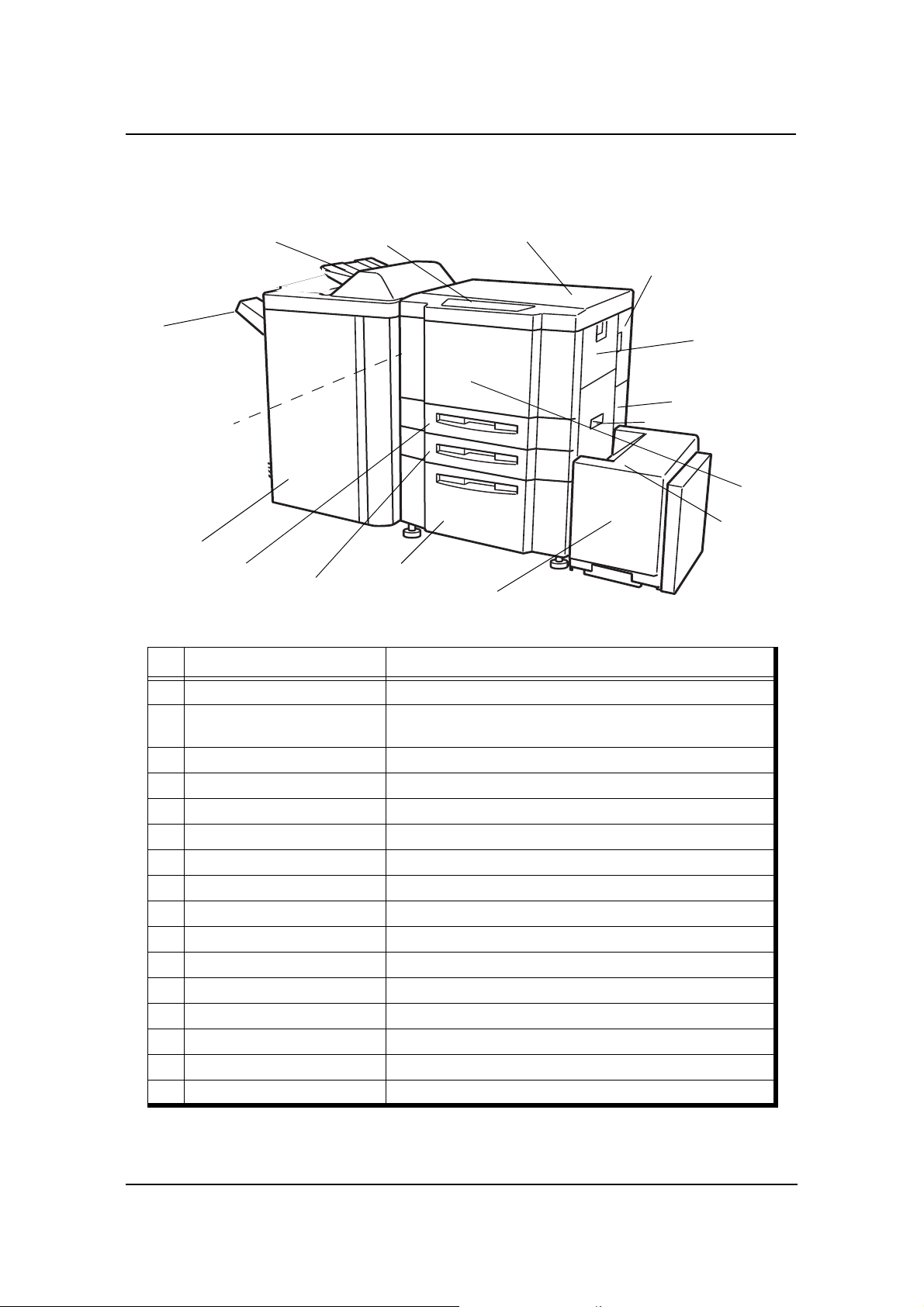
External View of the Printer
16. Upper Tray
6. Operator Control
1 1. Elevator Tray
10. Switch Back Cover
(Not Shown)
15. Finisher
9. Tray 3
8. Tray 2
Key Component Description
Panel
7. Tray 1
5. Toner Supply Cover
12. High Capacity Feeder
14. Toner Collector
Bottle Cover
4. Multi-bypass Tray
1. Power Switch
3. Vertical Path Cover
2. Front Cover
13. HCF Top
Cover
1 Pow er Switch Press to turn the printer on and off.
2 Front Cover
3 Vertical Path Cover Open to clear paper jams.
4 Multi-bypass Tray (MBT) Holds up to 150 sheets of paper.
5 Toner Supply Cover Open to replenish the toner supply.
6 Opera tor Control Panel (OCP) Displays printer status and menu information.
7 Tray 1 Holds up to 2,000 sheets of paper.
8 Tray 2 Holds up to 500 sheets of paper.
9 Tray 3 Holds up to 500 sheets of paper.
10 Switch Back Cover Open to clear paper jams.
11 Elevator Tray Output tray.
12 High Capacity Feeder (HCF) Holds up to 3,000 sheets of paper.
13 HCF Top Cover Open to clear paper jams.
14 Toner Collector Bottle Cover Open to replace the toner collector bottle.
15 Finisher For stacking, job offset, and stapling.
16 Upper Tray Output tray.
Open to replace units, clear paper jams, or clean the inside of
the printer.
Printer Overview 1-5
Page 16
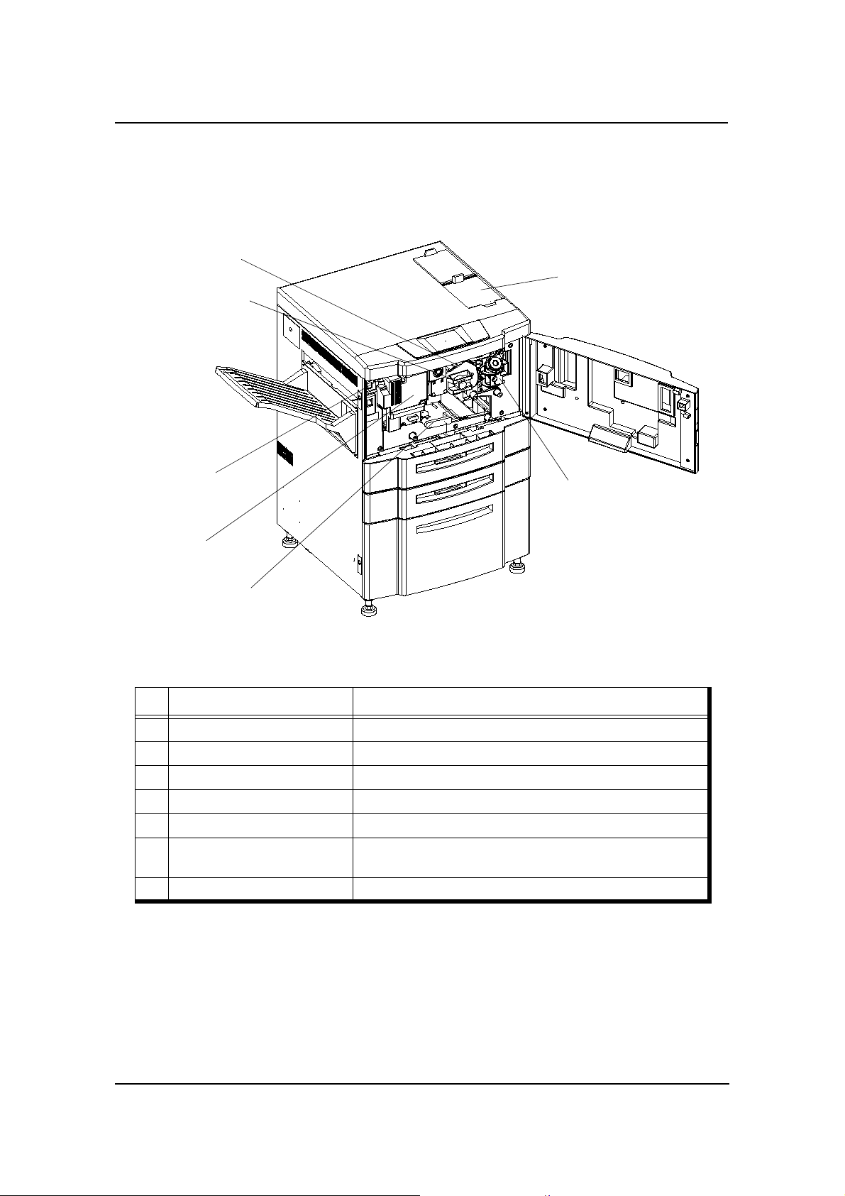
Internal View of the Printer
3. Drum Unit
2. Drum Center Lock
4. Fuser Latch
5. Fuser Unit
1. Toner Hopper Unit
6. Developer Duct
7. TH Handle
Key Component Description
1 Toner Hopper Unit Install the toner bottle here.
2 Drum Center Lock Holds the drum in place.
3 Drum Unit OPC drum.
4 Fuser Latch Provides access to the fuser unit.
5 Fuser Unit Fuses the toner on the paper.
6 Developer Duct
7 TH Handle Handle of the toner transfer unit.
Mount the developer bottle onto the developer duct to replace
consumed developer.
1-6 Printer Overview
Page 17

What This Chapter Provides
This chapter contains information on the following topics.
OCP Description
Menu Structure
Using the Menu Screens
Passwords
Chapter 2
Operator Control Panel
Operator Control Panel 2-1
Page 18
OCP Description
The Operator Control Panel (OCP) is a touch panel display that you use to set up print
options and monitor job and printer status. It is also used by the Network Administrator
to configure the printer and by the Service Technician to perform maintenance on the
printer.
Operator Control Panel
2-2 Operator Control Panel
Page 19
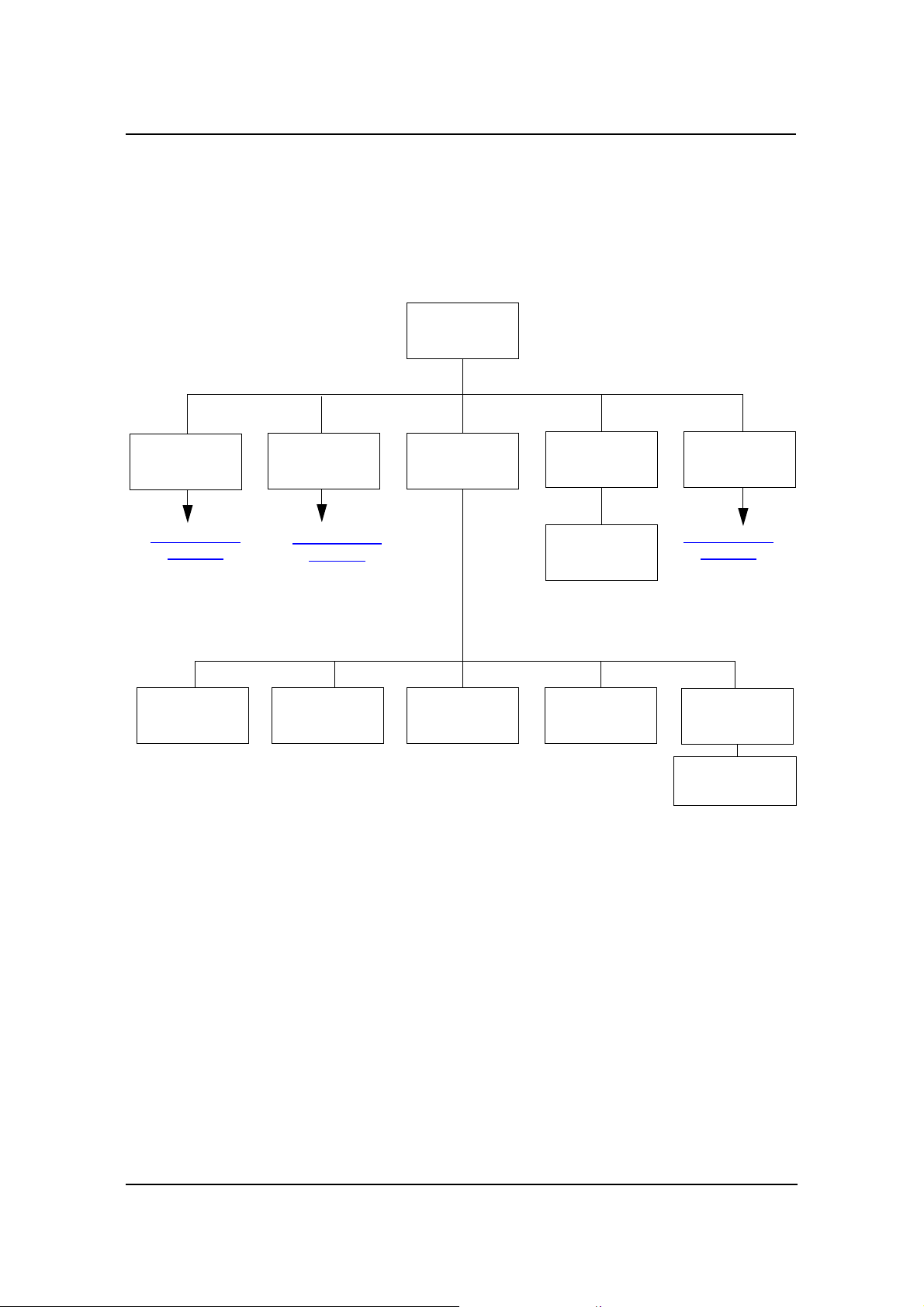
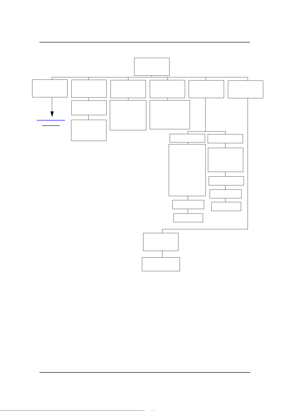
Menu Structure
The OCP menu is structured as shown in the following flowcharts. Each box in the
chart represents an OCP display screen. Use this flowchart to assist you in setting print
job options.
Main Menu
Printer Menu
Continued on
page 2-4
Setup Menu
Continued on
page 2-6
Reports Menu
Jobs Menu
Cancel Printing
Disk DirectorySummaryDemoStatus
Finisher Menu
Continued on
page 2-8
Fonts
• PCL Fonts
• PostScript Fonts
1
2
1
The Finisher Menu is only displayed when a Container Stacker is installed.
2
Available when PostScript is installed.
Operator Control Panel 2-3
Page 20
Printer Menu
Paper
Source
Continued on
page 2- 5
Default
Output
• Upper Tray
• Elevator Tray
• Stacker 5
• Stacker 6
• Stacker 7
• Stacker 8
2
2
2
2
Options
• Wait Timeout
• Duplex-Always
• LPD Queuing
• Auto Proof
Sample
PostScript
1
• Print Errors
• Best Fit
• Job Timeout
• Halftone Density
Print Quality
• Solid Black
• SquareBlk/Skew
• Half Tone
• GhostG
• Jitter
• Large Letters
• Diagonal Lines
• Density Scale
• Small to Large
• Text File 4%
• Cross Pattern
Select Paper
Source
Select Paper
Output
Test Print
• Staple:Front
• Staple:Rear
• Staple:Booklet
• Jogging
•
(More Options)
Finishing Test
Jogging
2
Select Paper
Source
Select Paper
Output
3
1
Available when PostScript is installed.
2
Available when the Container Stacker is installed.
2-4 Operator Control Panel
PCL
• Wide A4
• Requested Tray
Page 21
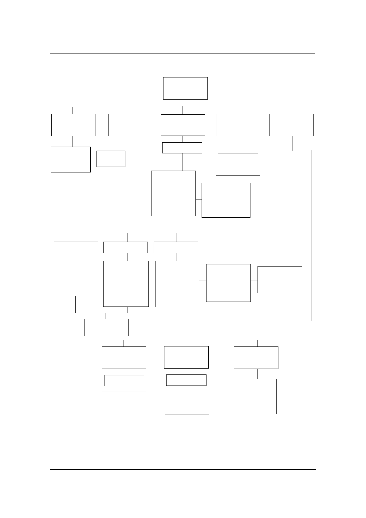
Paper
Source
Default
• AutoSelect
• 1
• 2
• 3
Tray 1
• Folio SEF
• Super B SEF
• Letter Tab LEF
• A4 Tab LEF
• Custom Size
2
Paper Size
• MBT
• HCF
Trays 2, 3
• Folio SEF
• Super B SEF
• Statement SEF
• Custom Size
• LetterTab LEF
• A4 Tab LEF
• Executive LEF
• Plain
• Bond
• Color
• Label
• Letterhead
• Preprinted
• Prepunched
2
• Letter LEF
• Letter SEF
• Ledger SEF
• Executive LEF
• Folio SEF
• Legal SEF
• Statement SEF
Paper Type
Select Paper
Source
1
MBT
MBT
Paper Color
Select Paper
Source
Paper Color
Settings
• Recycled
• Special
• Transparency
• Transparency-pp
• Other
• A4 LEF
• A4 SEF
• A3 SEF
• A5 SEF
• B5 LEF
• B4 SEF
1
(More Options)
1
• Super B SEF
• Letter Tab LEF
• A4 Tab LEF
• Custom Size
• Letter SEF
• A4 SEF
Paper Weight
Select Paper
Source
Paper Weight
Settings
1
Available when MBT is selected.
2
Available when the sensor plate in t he tray is set to the first position.
3
Available when the HCF is installed.
Tra y Adjust
Select Paper
Source
Tray Adjust
Settings
Ordered Sets
• 1
• 2
• 3
• MBT
3
• HCF
Operator Control Panel 2-5
Page 22
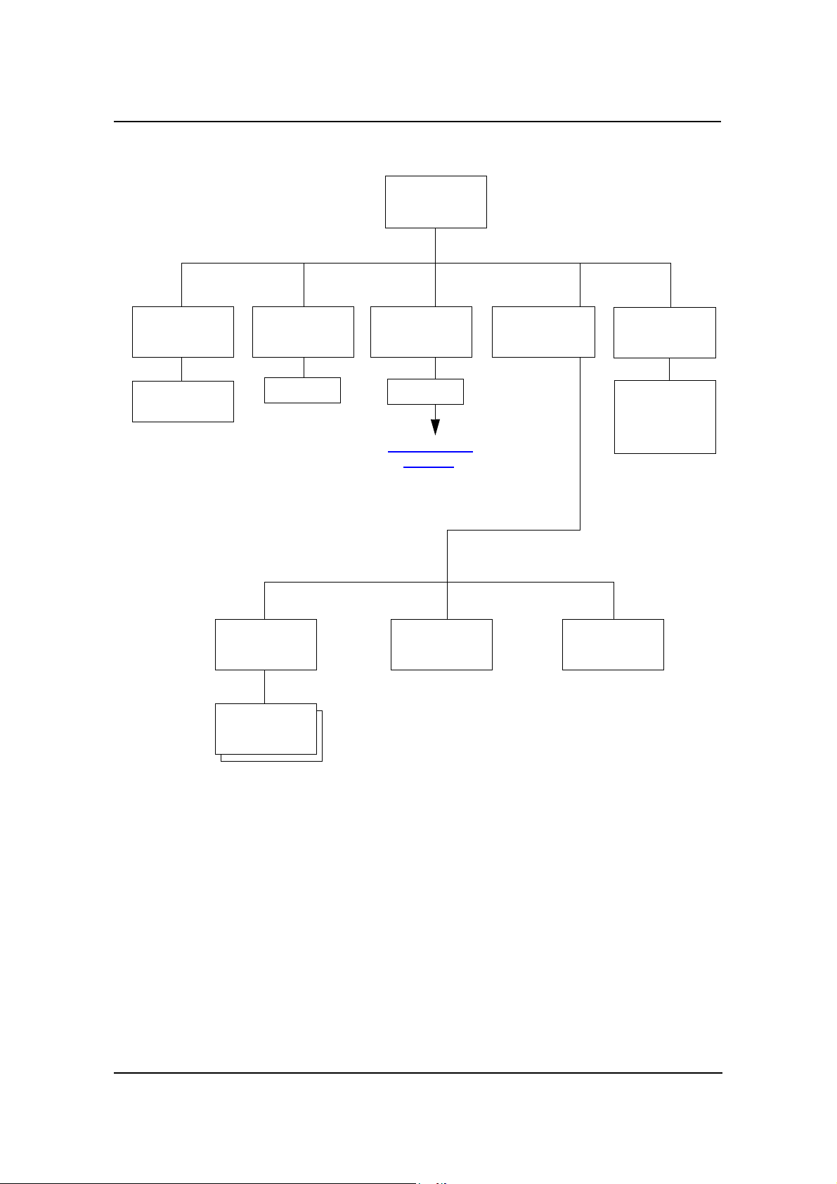
Setup Menu
OCP
• Contrast
• Volume
Service
Password
Developer Mix
• Exhaust
• Supply
1
Password
Continued on
page 2- 7
Drum Unit
ConsumablesSystem
Language
• English
• Deutsch
• Français
• Español
Fuser Web
1
Service menu items are for Service Technicians only and are not discussed in this manual.
2-6 Operator Control Panel
Page 23
System
Password
Reset
Ack Pulse
Width
Software
Log
• Compatible
• Bi-Directional
Subnet MaskIP Address
Mode
Parallel
Capture to
Gateway
Address
File
Network
Boot Method
• DHCP
• STATIC
Exit Jam
Recovery
HTTP Port
(More Options)
Calendar
• Time Zone
• Date
• Time
• Time Zone
Options
1
Available when Energy Save Mode is enabled.
2
Available when the Container Stacker is installed
3
Available when PostScript is installed.
Country
Code
Energy
Save Mode
Energy1
Save Time
Password
Emulation
• AutoSelec
• PostScript
• PCL
• PostScript
• Options
public
R/W
3
3
Online
3
• Auto Backup
• Output Cascade
• Best Fit Mode
(More Options)
Auto
Operator Control Panel 2-7
2
3
Page 24

Finisher Menu
1
Short Stacking
• 5
• 6
• 7
• 8
Decurler
• AutoSelect
• Enable
• Disable
1
Available when the Container Stacker is installed.
2-8 Operator Control Panel
Page 25
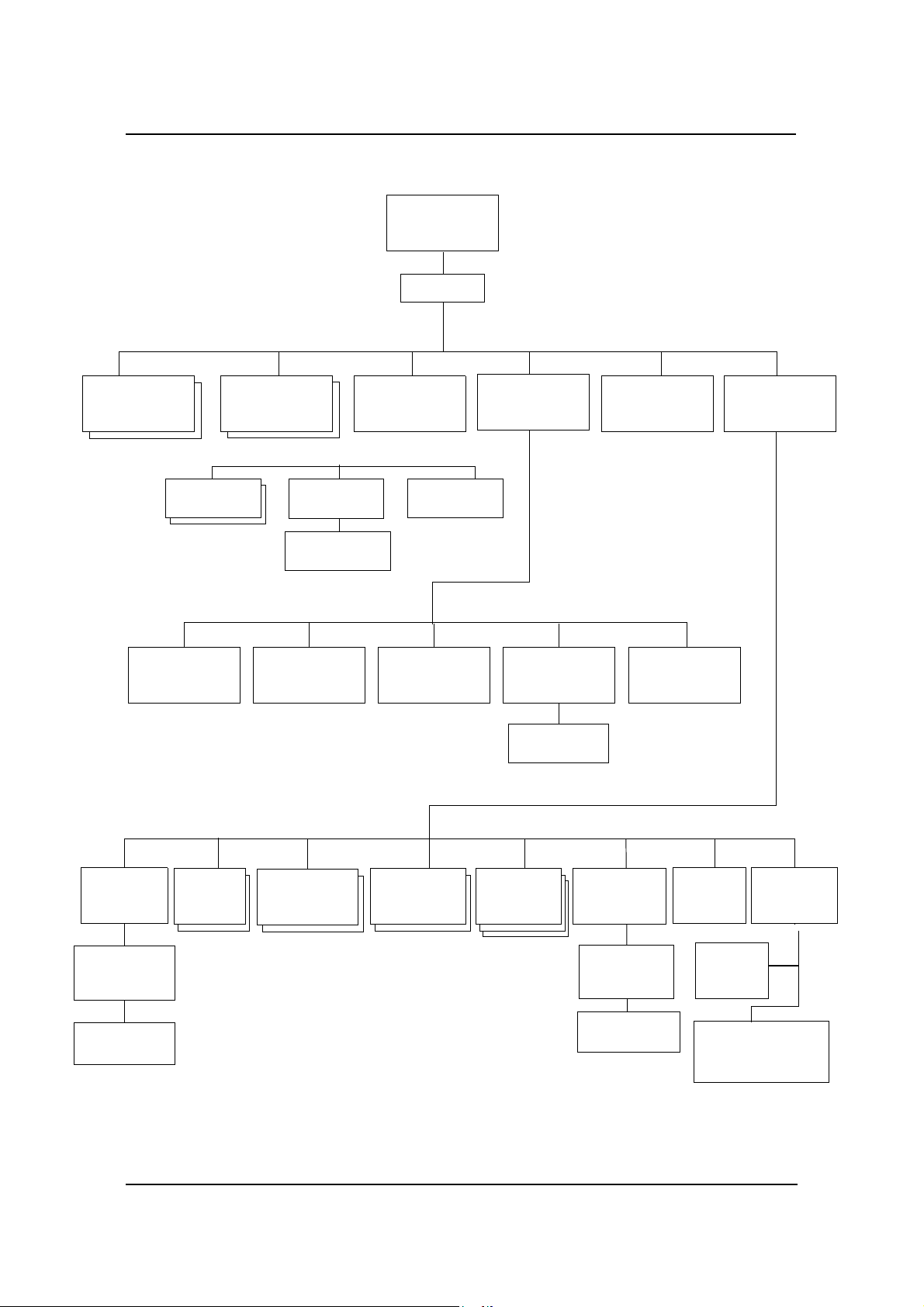
Using the Menu Screens
The menus are accessed via the touch panel. Each OCP screen consists of icons that
you use to make selections. The icons that are used through the OCP screens are shown
below. Examples of the OCP screens are shown on the following pages..
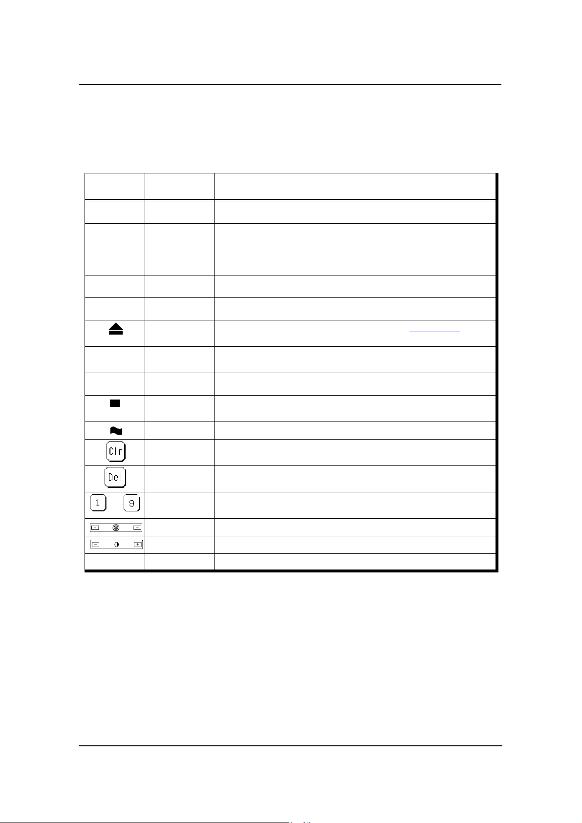
Icon or
Button
?
i
Name Function
Help Touch to display Help on the current screen.
Information From the Main Menu, displays information about the printer and con-
sumables.
From relevant screens, displays an illustration of the paper trays or fin-
isher trays.
Pause/Offline Tou ch to pause the printer.
Resume/Online When the printer is offline, touch to return to Ready status.
Return to Main
Menu/Cancel
Previous Menu Touch to cancel the current selection and return to the previous screen or
More Options Touch to display additional options for the current selection.
Enter or Accept Confirm or Done. Touch to confirm your selection and return to the previous
Sample Touch to duplicate a currently printing page and output to the sample tray.
Clear Button Touch to erase entire entry.
Touch to cancel the current selection and re turn to the
menu.
screen or menu.
Main Menu.
Delete Button Touch to erase last character entered.
–
Ten Key Use to enter numeric values.
Volume Use to adjust volume of the OCP touch pad.
Contrast Use to adjust the contrast level of the OCPdisplay.
Status Bar Displays the current screen name and/or any system messages.
Operator Control Panel 2-9
Page 26
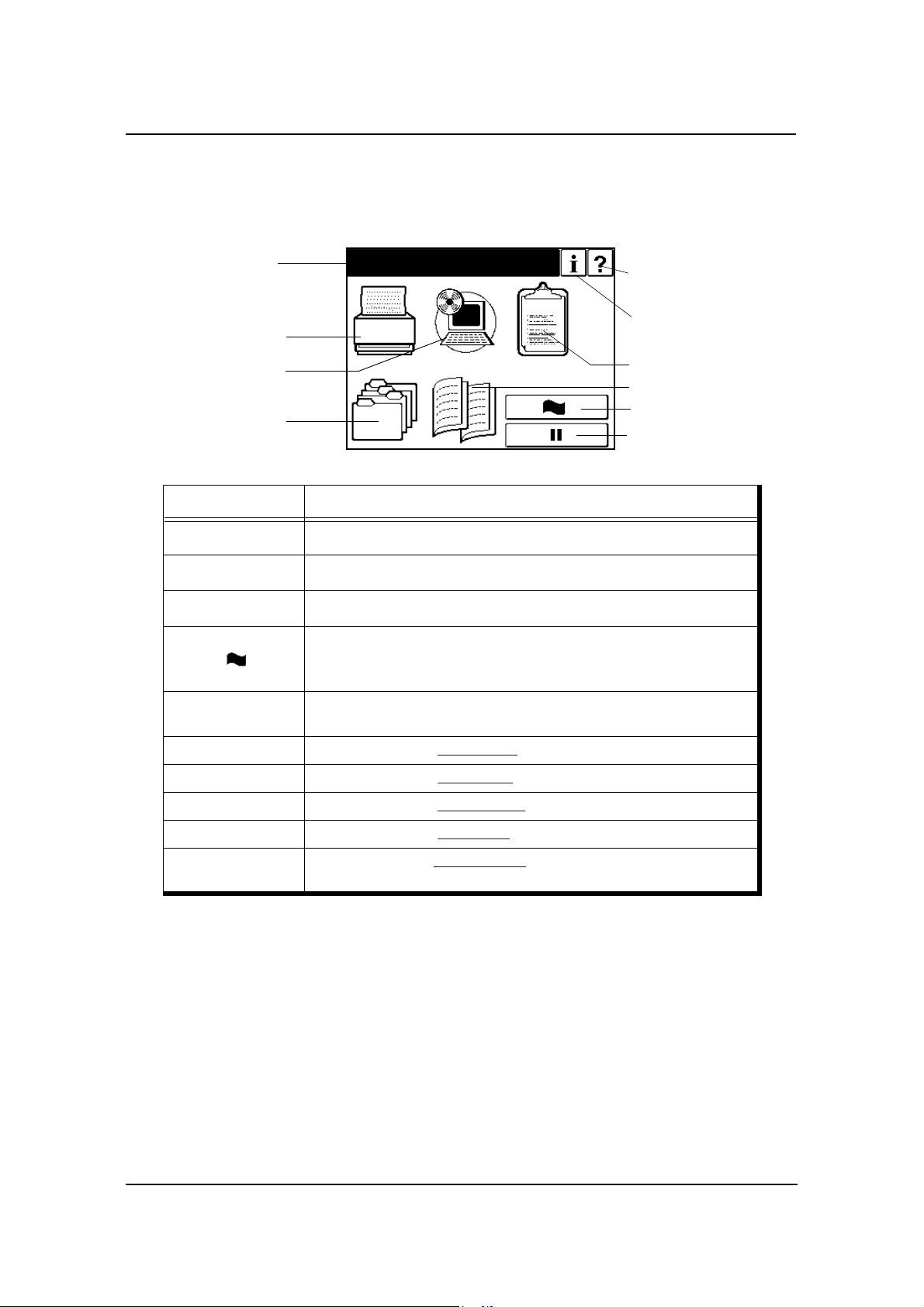
Main Menu
1.The Main Menu screen is shown below . A description of the elements that make up
the screen follows.
Status Bar
Printer Menu
Setup Menu
Jobs Menu
Icon Function
Status Bar
?
i
Ready
Help
Current Screen
Information
Reports Menu
Finisher Menu
Sample
Pause/Offline
Touch to open Main Menu Help.
Touch to display information about the printer and consumables.
Touch to pause the printer.
Touch to duplicate a current printing page and output to the
•Standard Finisher: Upper tray
•Container Stacker: Sample tray
Consists of one or two lines of text for displaying messages and instruc-
tions.
Printer Menu Touch to display the Printer Menu
Setup Menu Touch to display the Setup Menu
Reports Menu Touch to display the Reports Menu.
Jobs Menu Touch to display the Jobs Menu.
Finisher Menu
Touch to display the
Stacker is installed.
Finisher Menu. Available only when a Container
.
.
2-10 Operator Control Panel
Page 27
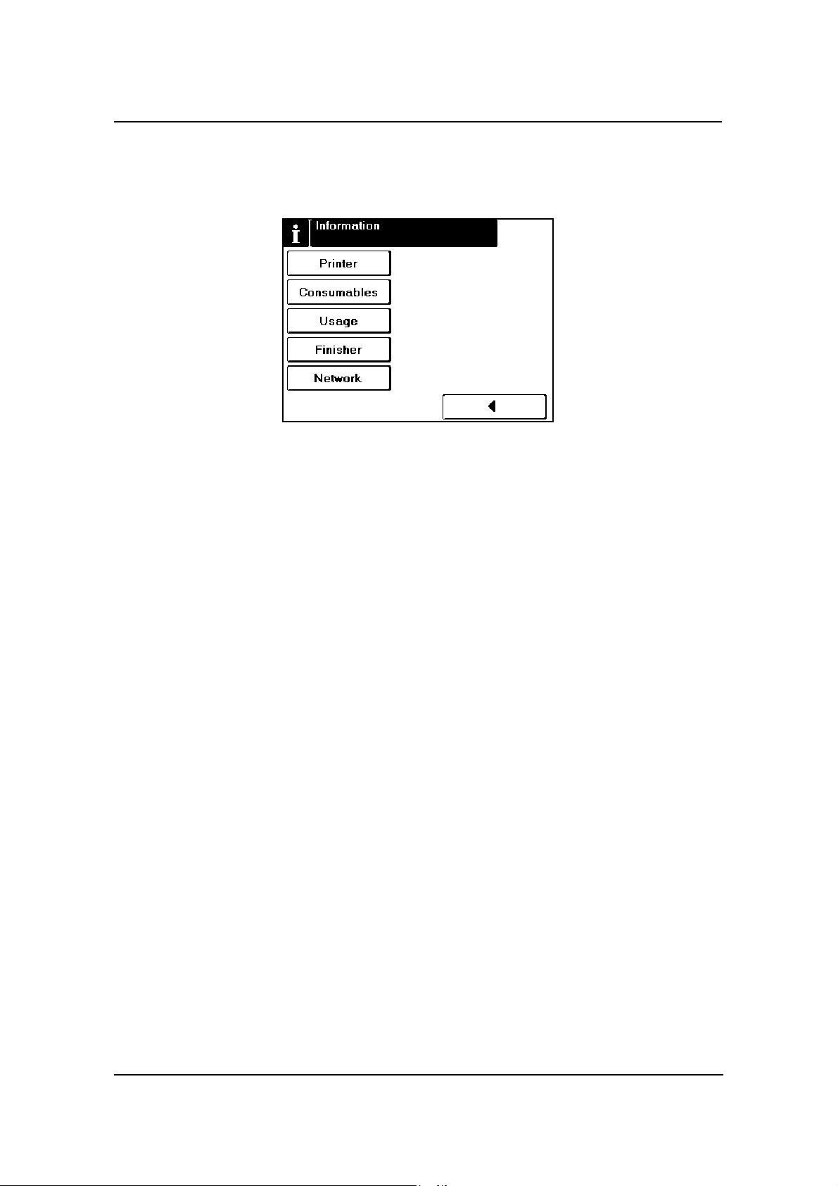
Information
When you select Information from Main Menu, this screen is displayed. You use it to
confirm about printer settings and consumables described as below.
Printer
Consumables
Displays information about the engine and controller software revision, error
counts, and the current paper type and source settings.
Displays the status of the consumables: Toner, Developer Mix., Drum, and Fuser
Web.
Usage
Displays current information regarding print density, preventative maintenance,
and page counts.
Finisher
Displays information regarding the status of the Finisher.
Network
Displays information such as MAC and IP Address, Gateway Address, Subnet
Mask and HTTP Port.
Operator Control Panel 2-11
Page 28
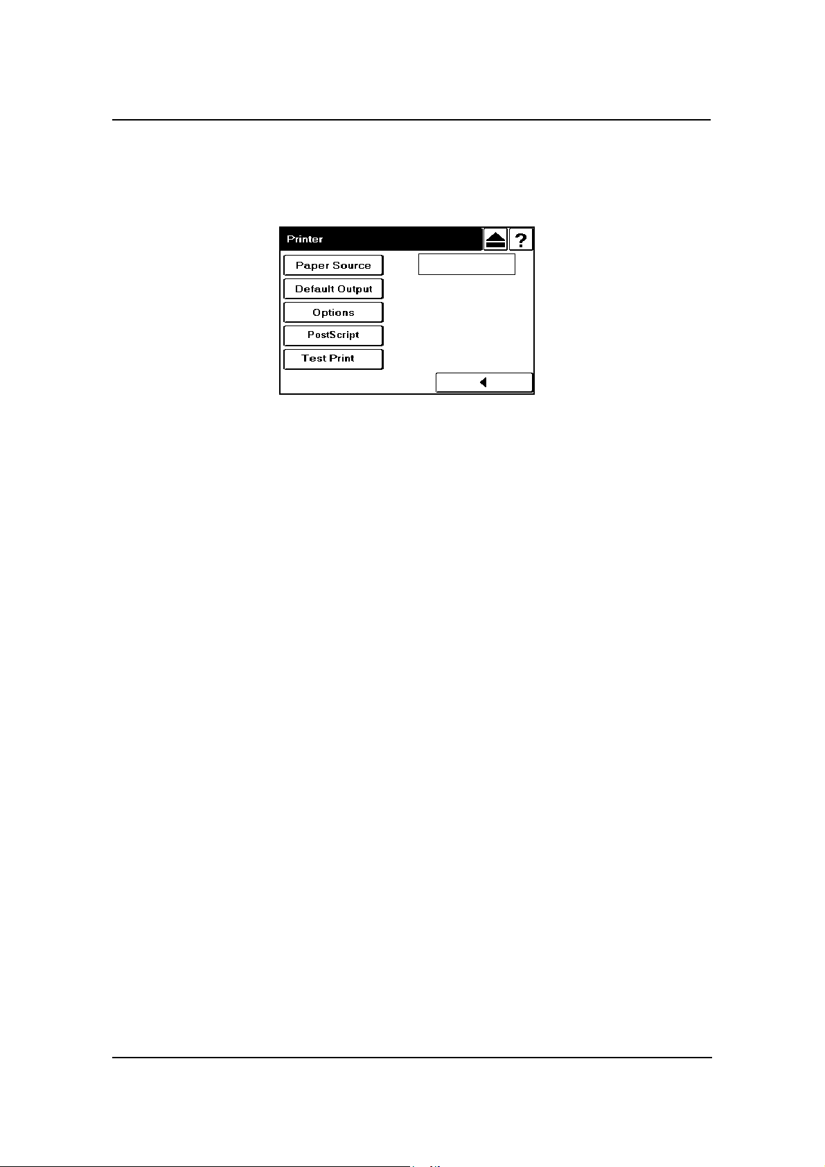
Printer Menu
When you select Printer from the Main Menu, this screen is displayed. You use the
Printer Menu to gain access to the printing options described in the table below.
Paper Source
Default
PCL
Defines the default paper tray. Use this when the paper source is not
designated by a host command. If a command from the host defines the paper
source, the OCP setting is ignored. When “AutoSelect” is selected, tray is
automatically selected according to paper size and/or paper type defined by
host.
Paper Size
When Paper Size is selected the paper size of the currently selected paper
source is displayed. When the “Custom Size Switch” in the tray is set to
“Standard”, paper size is automatically detected. See “Setting the Custom
Paper Size Values” on page 3-16 for more information.
Paper Type
Defines the paper type to desired input tray. The paper type screen displays
currently selected paper type, and the option buttons to select another paper
type. See “Setting the Paper Type” on page 3-17 for more information.
Paper Color
Sets the paper color for the selected input tray . The paper color screen displays
the currently selected paper color, and the option buttons to select another
paper color. There are 7 pre-defined colors and up to 80 custom colors to
choose from. Custom colors are defined using the Web Utilities. See “Setting
the Paper Color” on page 3-17 for more information.
Paper Weight
Defines the paper weight for the input tray. The paper weight screen displays
the currently defined paper weight, and the options to redefine the paper
weight settings. Options include bond, index and g/m
2
. See “Setting the Paper
Weight” on page 3-17 for detailed information and instructions.
2-12 Operator Control Panel
Page 29

Tra y Adjust
The print position can be adjusted vertically and horizontally using the Tray
Adjust option. When printing in duplex mode, you can set different tray adjust
values for the front side and back side of the paper. See “Setting the Tray
Adjust Values” on page 3-16 for detailed information and instructions.
Ordered Sets
You can define an ordered set by specifying the number of pages in the set and
the paper source tray(s) that contain the ordered set pages. The printer will
support input tray cascading for ordered sets based on paper size and media
type. See “Ordered Sets” on page 3-18 for detailed information and
instructions.
Default Output
Use this option when the output tray is not designated by a host command.
Options include Upper Tray, Elevator T ray and Stacker 5, 6, 7 and 8, (if installed).
If a command from the host defines the output tray, the OCP setting is ignored.
Options
Wait Timeout
Defines the time period (in seconds) from reception of last data to the
reception of next data. If data is not received within the defined period, the job
terminated. A command from the host will override the OCP setting.
is
LPD Queuing
Can be set to enable or disable. The factory default is disabled. When enabled
the printer will accept and queue additional print jobs while a data transfer is
in process for another job.
Duplex Always
Can be set to enable or disable. When set to enable, the printer will always
print in duplex mode.
Auto Proof Sample
This function provides automatic proof sample printing instead of manually
pressing the Sample button on the OCP. The auto proof sample interval is
0 - 5,000 pages in 500 sheet increments (0, 500, 1,000, 1,500, ... 5,000). For
example, if the interval is set to “500”, the printer will automatically output a
proof sample to the sample tray every 500 sheets. If the interval is set to “0”,
the function is disabled.
PostScript
Print Errors
Can be set to enable or disable. When set to enable, the printer will print an
error page when a PostScript error occurs.
Operator Control Panel 2-13
Page 30

Best Fit
Can be set to enable or disable. When enabled, if the requested paper size is
not present in any tray, the printer will select the closest available paper size
and scale the image to fit. Best Fit works in conjunction with the Best Fit
Mode option in the System Menu.
Job Timeout
Defines the time limit for processing of the PostScript job. The valid range is
0 or 15 - 999.
Halftone Density
Halftone Density can be adjusted to Light, Medium, Dark or Custom.
NOTE:
The Halftone Density menu is only displayed when the Halftone Selection
in the Service menu is enabled.
Test Print
Use this button to print a test pattern for checking the print quality or the print
position. A list of test patterns is shown on page 2-4.
PCL
Wide A4
Can be set to enable or disable. When set to enable, the printer changes the
margin/printable area of A4 paper so that 80 10-pitch characters may be
printed on a line.
Requested Tray
Exclusively - Printer should print from the requested tray only.
First - Printer should print from the requested tray first.
2-14 Operator Control Panel
Page 31

Setup Menu
When you select Setup from the Main Menu, this screen is displayed. Use it to gain
access to the Setup option screens that are described in the table below.
OCP
Volume
The volume of the OCP touch pad can be adjusted within a range of 0 to 5.
The factory default is 3.
Contrast
The contrast of the OCP can be adjusted within a range of 1 to 16. The factory
default is 10.
Service
The Service option is used by an Authorized Service Technician and is password
protected.
System
The System option is password protected. Contact your System Administrator for
access to these options.
Reset
Press to reboot the printer.
Software Log
Press to create a software log. A power cycle is required after creating the log.
Parallel
Network
Defines the parameters of the network. The network is displayed as
10/100/1000 (AUX). Other Network parameters include: IP Address, Subnet
Mask, Gateway Address, Boot Method, HTTP Port
Calendar
Time Zone - GMT -12:00 to GMT +12:00.
Date - 0000/00/00 (Year/Month/Day)
Time - Set printer clock
Operator Control Panel 2-15
Page 32

Country Code
Select the appropriate country code used in international phone numbers. A
complete list is available in your telephone book or on the Internet. Country
Code is not necessarily related to language. The default setting is 1.
Energy Save Mode
Can be set to enable or disable.
Energy Save Time
When Energy Save Mode is enabled use this option to set the wait time (in
minutes) before the printer enters Energy Save Mode.
Password
Use to change the System password. The system password is used by your
System Administrator and provides access to the system parameters.
Emulation
Options are AutoSelect, PostScript and PCL.
Public R/W
Can be set to enable or disable. Enable allows read/write when SNMP
community name is Public.
Auto Online
Can be set to enable or disable. When disabled, if the offline button is pressed
the printer will remain in an offline status until the button is pressed again.
When enabled, the printer will automatically return to an online status within
3-5 minutes without pressing the button.
Auto Backup Time
Valid range is 0 - 23 (corresponding to the hour of the day). A system data
backup will be performed if the printer is on at the set time.
Best Fit Mode
Can be set to Standard or Compatible. Best Fit Mode works in conjunction
with the Best Fit setting.
Standard: Mode for PostScript Version 3015 command sets.
Compatible: Mode for PostScript Version 3011 command sets.
Output Cascade
Lower to Upper - The lower trays are given priority within each stacker.
Upper to Lower- The upper trays are given priority within each stacker.
Available only when the optional Container Stacker is attached. When two
Container Stackers are attached the setting applies to both. The priority
between Container Stackers is Container Stacker 1 first, then Container
Stack er 2.
Consumables
Use to replace the Developer Mix, Drum Unit, and Fuser Web
Language
Use to set the OCP language to English, Deutsch, Français, or Español.
2-16 Operator Control Panel
Page 33

Reports Menu
When you select Reports from the Main Menu, this screen is displayed. You use it to
print the reports described below.
Status
Touch to print a status report and return to the Main Menu. The status report
shows the current configuration of the printer and printer usage information.
Demo
Touch to print a demo report and return to the Main Menu. The demo report
shows the printer specifications such as speed, paper handling, resolution, etc.
Summary
Touch to print a summary report and return to the Main Menu. The summary
report shows processor, connectivity, RAM and other miscellaneous information.
Disk Directory
Touch to print a disk directory report and return to the Main Menu.
Fonts
Touch to print the fonts summary options (PCL fonts and Postscript fonts).
Operator Control Panel 2-17
Page 34

Finisher Menu for the Container Stacker
When you have the optional Container Stacker installed and you select the Finisher
icon from the Main Menu, this screen is displayed. You use it to gain access to the
Container Stacker options.
For additional information on the Container Stacker, refer to the Container Sta c ker
User’s Guide.
Short Stacking
Can be set to enable or disable. When enabled, the paper stack is limited to 75%
of the stacker capacity.
Decurler
The options for the Decurler are AutoSelect, enable, or disable. Activating the
decurler may cause paper jams when printing with 28 lb. bond or heavier paper.
2-18 Operator Control Panel
Page 35

Jobs Menu
When you select Jobs icon from the Main Menu, this screen is displayed. You use the
Jobs Menu to cancel print jobs in the printer.
List of Jobs
Job-01 1/3-12 ““ 16:02 P
Job-02 0/1-1
Text-fil 0/1-1
““ 16:03 P
““ 16:08 P
Scroll Bar
““ 16:02 P
Time
User Name
Job Name
Current Copy
Total Copy
Scroll Bar
Job-01
Page Count
1/3-12
Touch to scroll the list of jobs.
Select All
To cancel all print jobs, press Select All, then press Delete.
Clear All
Press Clear All to deselect all print jobs.
Delete
To cancel a single job, touch the job name, then press Delete.
Job Status
P: Pause A: Active
C: Cancel
Operator Control Panel 2-19
Page 36

Passwords
Passwords provide security to restrict access to system parameters and certain printer
maintenance functions. Two types of passwords are available with your printer: a
system password and a service password.
The system password is used by your System Administrator and provides access to the
system parameters. The service password is used by your Service Technician and
provides access to service and maintenance functions as well as the system parameters.
For additional information, contact your System Administrator.
NOTE:
If the system password is lost it must be set up again. Contact your
authorized Service Technician.
2-20 Operator Control Panel
Page 37

What This Chapter Provides
This chapter contains information on the following topics.
Paper Weights
Unacceptable Paper
Storing Paper
Paper Sizes, Types, and Trays
Loading Paper
Setting Custom Paper Size Values
Setting Tray Adjust Values
Setting the Default Paper Source
Setting the Paper Type
Chapter 3
Paper Handling
Setting the Paper Weight
Setting the Paper Color
Ordered Sets
Paper Handling 3-1
Page 38

Paper
T o obtain good print quality , use the recommended paper and properly position it in the
correct trays. For the desired paper orientation, see the labels on the trays. Refer to
Appendix C for detailed information about paper specifications and printing on special
print media.
Paper Weight s
The printer accepts the following paper weights in all paper trays, including the MBT
and HCF:
Bond paper: 16-53 lb (60-199 g/m
Index paper: 90-110 lb (163-199 g/m
Paper Color
The printer accepts color paper in all paper trays, including the HCF. The seven predefined colors are listed below. Additionally, you can define up to 80 custom colors
using the Web Utilities.
White
Pink
2
)
2
)
Yellow
Buff
Goldenrod
Blue
Green
Unacceptable Paper
Avoid using the following media as they cause paper jams and print quality problems.
Excessively thick or thin paper
Paper that has already been printed (preprinted letterhead is allowed)
Wrinkled, torn, or bent paper
Moist or wet paper
Curled paper
Paper with an electrostatic charge
Glued paper
Paper with special coating
Colored paper with surface treatment
Paper unable to withstand temperature of 302°F (150° C)
Thermal paper
3-2 Paper Handling
Page 39

Carbon paper
Paper with paper fasteners, ribbons, tape, etc., attached
Heavily textured paper
Label stock with exposed backing sheets
Storing Paper
Store the paper properly to avoid print quality problems and paper jams.
Store paper horizontally, in a flat, dry location to avoid wrinkling, bending,
curling, etc.
Store paper away from direct sunlight.
Store any unused paper in its original packing.
Paper Handling 3-3
Page 40
Paper Sizes, Paper Types, and Printer Input Trays
The following tables show which paper sizes and types can be used with the printer's
input trays. The paper size is shown in both millimeters and inches. The term SEF
indicates the paper is being fed into the printer short edge first and the term LEF
indicates the paper is being fed into the printer long edge first.
Paper Size
A5 (SEF) 149.0/5.83 210.0/8.26 2, 3 only
B5 (LEF) 257.0/10.13 182.0/7.17
A4 (SEF) 210.0/8.3 297.0/11.7
A4 (LEF) 297.0/11.7 210.0/8.3
B4 (SEF) 257.0/10.1 364.0/14.3
A3 (SEF) 297.0/11.7 420.0/16.5
Letter (LEF) 279.0/11.0 216.0/8.5
Letter (SEF) 216.0/8.5 279.0/1 1.0
Tabstock (Letter LEF) 374.0/11.0 279.0/9.0
Tabstock (A4 LEF) 297.0/11.7 225/8.85
Folio (SEF) 216.0/8.5 330.0/13.0
Legal (SEF) 216.0/8.5 356.0/14.0
Ledger (SEF) 279.0/11.0 432.0/17.0
Super B (SEF) 305.0/12.0 457.0/18.0
Statement (SEF) 216.0/8.5 140.0/5.5
Executive (LEF) 267.0/10.5 184.0/7.255
Custom
(0.1 mm/0.1 in. increments)
Leading Edge
mm/inch
139.7 to 304.8/
5.5 to 12.0
Side Edge
mm/inch
182.0 to 457.2/
7.2 to 18.0
Tray
1, 2, 3
99
99
999
99
99
999
99
99
9
99
99
99
99
2, 3 only
2, 3 only
9
*
HCF MBT
9
9
9
9
* Tray 1 can be adjusted; however, the physical settings are limited to standard paper sizes. Use
of custom size paper may result in skewing.
Paper Type Tray 1, 2, 3 HCF MBT
Label
Letterhead
Pre-printed
Pre-punched
Plain
Bond
Color
Special
Other
Transparencies
3-4 Paper Handling
999
999
999
999
999
999
999
999
9
9
Page 41

Loading Paper
Load paper into the trays according to the instructions that follow. See “Loading
Special Media” on page 3-12 for directions on loading prepunched and preprinted
paper, as well as tab stock. Paper can be loaded while a print job is running, except into
the tray that is currently in use.
Loading Paper in Tray 1
WARNING!
Do not open T ray 1 if the Fuser Unit is pulled out. The printer may tip over
causing personal injury or damage to the printer.
1. Open the tray by pulling it by the handle.
2. Adjust the size guide to the proper size. The available sizes are marked on the tray.
Paper Handling 3-5
Page 42

3. Adjust the sensor plate to the proper size. Size markers are located on the sensor
plate in the following order: triangle (special), B5, A5, LGR, LGL, LTR, B4, A3,
and A4.
If the paper size you need is not listed, set the sensor plate to triangle (the first
position). Then, in Step 6, you will select the paper size from the OCP display.
4. Place the paper into the tray.
NOTE:
The paper should be loaded no higher than the Max. level indicator. The
Max. level indicator is located inside the tray.
5. Close the tray.
6. If you set the sensor plate to triangle in Step 3, select the paper size from the OCP
by making the following selections:
Printer / Paper Source / Paper Size / tray #/ paper size
7. Adjust the paper weight. The default paper weight is 20 lb. bond. If necessary,
change the paper weight by making the following selections:
Printer / Paper Source /
8. Select Index, Bond, or g/m
3-6 Paper Handling
/ Paper Weight / tray #
2
, then use the keypad to input the weight and press .
Page 43

Loading Paper in Tray 2 or 3
1. Open the tray.
2. Adjust the size guide to the proper size. The available sizes are marked on the
bottom of the tray.
3. Adjust the sensor plate to the proper size. Size markers are located on the sensor
plate in the following order: triangle (special), B5, A5, LGR, LGL, LTR, B4, A3,
and A4.
If the paper size you need is not listed, set the sensor plate to triangle (the first
position). Then, in Step 6, you will select the paper size from the OCP display.
Paper Handling 3-7
Page 44

4. Place the paper into the tray.
NOTE:
The paper should be loaded no higher than the Max. level indicator. The
Max. level indicator is located inside the tray.
5. Close the tray.
6. If you set the sensor plate to triangle in Step 3, select the paper size from the OCP
by making the following selections:
Printer / Paper Source / Paper Size / tray # / paper size
7. Adjust the paper weight. The default paper weight is 20 lb. bond. If necessary,
change the paper weight by making the following selections:
Printer / Paper Source /
8. Select Index, Bond, or g/m
/ Paper Weight / tray #
2
, then use the keypad to input the weight and press .
3-8 Paper Handling
Page 45

Loading Paper into the MBT
1. Open the MBT by pulling it by the handle.
2. Adjust the size guide to the proper size. The paper size positions are marked on
the bottom of the tray and on the top of the size guide.
Paper Handling 3-9
Page 46

3. Push down the paper tray.
4. Set the paper onto the tray.
3-10 Paper Handling
Page 47

Loading Paper into the HCF
WARNING!
The table inside the HCF automatically descends when you open the door
of the HCF. Do not allow anything to be caught between the table and the
bottom of the HCF.
1. Open the door of the HCF by pulling it by the handle. The table inside the HCF
automatically moves to its lowermost position and stops.
2. Set the paper into the HCF. (The HCF is set to handle Letter LEF or A4 LEF size
only. A service call is required to change from one size to the other.)
NOTE:
The paper should be loaded no higher than the Max. level indicator. The
Max. level indicator is located inside the HCF.
3. Close the door.
Refer to graphic i
Paper Handling 3-11
Page 48

Loading Special Media
Pre-punched Paper
Load pre-punched paper as indicated in the following diagrams. Refer to Appendix C
for more information about using pre-punched paper.
Table 0-1. Simplex Printing (Single-sided)
Paper Size Orientation
Loading into
Tray 1 - 3 MBT or HCF
Letter/A4
Ledger/A3 Portrait
Ledger/A3 Landscape
Letter/A4 Portrait
Letter/A4 Landscape
Portrait and
Landscape
Ledger/A3
Portrait and
Landscape
Arrows indicate paper feed direction.
3-12 Paper Handling
Page 49

Table 0-2. Duplex Printing (Double-sided)
Paper Size Orientation
Portrait and
Letter/A4
Ledger/A3
Ledger/A3
Ledger/A3
Landscape
(Long Edge Bind)
Portrait
(Short Edge Bind)
Landscape
(Short Edge Bind)
Portrait and
Landscape
(Long Edge Bind)
Loading into
Tray 1 - 3 MBT or HCF
Letter/A4
Letter/A4
Portrait
(Short Edge Bind)
Landscape
(Short Edge Bind)
Arrows indicate paper feed direction.
Paper Handling 3-13
Page 50

Loading Pre-printed Paper
Load pre-printed paper as indicated in the following table. Refer to Appendix C for
more details about using pre-printed paper.
Paper Type
Front/Back Side
Predetermined
Page Number
Predetermined
Print
Mode
Simplex Front side down Front side up
Paper up to 9 in. (feed direction),
Duplex
Simplex First sheet on top, face down First sheet on top, face up
Duplex
front side down
Paper longer than 9 in. (feed
direction), front side up
Paper up to 9 in. (feed direction),
first sheet on top, face down
Paper longer than 9 in. (feed
direction), first sheet on top, face
up
Tray 1 - 3 MBT/HCF
Loading Into
Front side up
First sheet on top, face up
3-14 Paper Handling
Page 51

Loading Tab Stock
1. Load tab stock as shown in the illustration below.
NOTE:
Avoid bending the tabs or the corners of the tab dividers as this will
increase the likelihood of a jam occurring during the printing process. If a
jam does occur, refer to page 4-25 for instructions on jam recovery.
In the main paper trays, place the straight edge of the tab stock against the straight
right leading edge of the paper tray. The tabs should be on the left, also known as
the trailing edge. In the MBT, place the straight edge into the machine. Tab stock
cannot be used in the HCF.
Top
Bottom
Load only complete tab sets. The first tab in the set should be on top of the stack
and the last tab on the bottom. Adjust the paper guides so that they hold the tab
stock securely in position in the tray.
NOTE:
You must set the sensor plate in the tray to the first position (denoted by a
triangle).
2. Select the paper size from the OCP by making the following selections. (If the tab
stock is not 9 in. by 11 in., select Custom Size.)
Printer / Paper Source / Paper Size / tray number / LetterTab or Custom Size
3. If you selected Custom Size in step 2, see “Setting the Custom Paper Size Values”
on page 3-16 for instructions on entering the custom paper size.
Paper Handling 3-15
Page 52

Setting the Custom Paper Size Values
If the paper size you have selected is a custom size you must set the paper size using
the OCP. First, follow the steps for loading paper into the desired tray, then perform
these steps.
1. On the Custom Paper Size screen, touch the value box for the leading edge (the
arrow in the illustration points to the leading edge). The Custom Paper Size Input
screen is displayed.
2. Using the number pad, enter the value for the leading edge of the paper.
3. Press the
entered is shown.
4. Touch the value box for the side edge. The display returns to Custom Paper Size
Input.
5. Using the number pad, enter the value for the side edge of the paper.
6. Press the
you have entered are displayed.
7. Press the
key . The display returns to Custom Paper Size and the value you have
key. The display returns to Custom Paper Size and now both values
key. Your custom paper size settings are now saved.
Setting the Tray Adjust Values
The tray adjust feature is used when it is necessary to shift the image on the printed
page. You can shift the image feed direction +1.0 in (25.4 mm) or -0.5 in (12.6 mm)
and you can shift the image ±0.5 in. (12.6 mm) in the scan direction. When pri nting in
duplex mode, you can set different tray adjust values for the front side and back side of
the paper.
1. To display the Tray Adjust screen, make the following selections from the OCP:
Printer / Paper Source/
2. On the Tray Adjust screen, touch the left-most value box. The Tray Adjust Input
screen is displayed.
/ Tray Adjust / tray number
3. Using the number pad, enter the value for the feed direction of the paper. For
example, entering +1.0 moves the image 1.0 in. to the right on the printed page.
4. Press the
have entered is shown.
5. Touch the bottom-most value box. The display returns to Tray Adjust Input.
6. Using the number pad, enter the value for the scan direction of the paper. For
example, entering +0.5 moves the image 0.5 in. to the top of the printed page.
7. Press the
values you have entered are displayed.
8. Press the
3-16 Paper Handling
key. The display returns to the Tray Adjust screen and the value you
key. The display returns to the Tray Adjust screen and now both
key. Your tray adjust settings are now saved.
Page 53

Setting the Default Paper Source
The Default Paper Source feature is used when the paper source is not specified in the
job.
1. To set the Default Paper Source make the following selections from the OCP:
Printer / Paper Source / Default / Tray # or AutoSelect /
Setting the Paper Type
The Paper T ype feature is used when the type of paper being used is anything other than
Plain.
1. To set the paper type for each tray make the following selections from the OCP:
Printer / Paper Source / Paper Type / Tray # / desired paper type /
Setting the Paper Weight
The Paper Weight feature is used when the paper weight being used is anything other
than 20 lb..
1. T o set the paper weight for each tray make the following selections from the OCP:
Printer / Paper Source / >> / Paper Weight / T ray #
Using the number pad, enter the value for paper weight and press the
Setting the Paper Color
The Paper Color feature is used when the paper color being used is anything other than
white.
key.
1. To set the paper color for each tray make the following selections from the OCP:
Printer / Paper Source / Paper Color / >> / Tray #
Paper Handling 3-17
Page 54

Ordered Sets
Using the OCP or the WEB you can define an ordered set by specifying the number of
pages (12 max.) in the set and the paper source tray(s) that contain the ordered set
pages. The printer will support input tray cascading for ordered sets based on paper size
and media type
NOTE:
The printer can support only one ordered set size at a time; therefore, make
sure the paper size and media type for each tray in the cascade are the same.
PCL tray grouping is also supported for ordered sets. All trays in a group must have the
same configuration to allow cascading. Trays not included in the group must have a
different configuration.
NOTE:
For more information on PCL Tray Grouping refer to the Web Utilities
Guide and/or the PCL Programming Guide.
In the event that a paper jam, job cancellation, or other recoverable printer error occurs
while printing ordered sets, the printer will prompt you to clear the paper path. When
the paper path is clear, press Continue on the OCP. The printer will automatically
remove the remaining sheets of the ordered set to the sample tray , reprint the set(s) that
were in the paper path, and complete the job.
Some examples of ordered sets are:
Tabs
NCR
Prenumbered pages
Special forms
3-18 Paper Handling
Page 55

Define the Ordered Sets
1. From the OCP make the following selections:
Printer / Paper Source /
The Ordered Sets and Size screen will be displayed.
2. Select the tray(s) and the number of pages in the set.
3. Press the
4. Load the ordered set pages into the tray(s).
NOTE:
When loading ordered media to a tray you must load the paper in complete sets
If you print a subset of the complete set the unused pages will be delivered to the
sample tray.
key. Your settings are now saved.
/ Ordered Sets
Paper Handling 3-19
Page 56

3-20 Paper Handling
Page 57

What This Chapter Provides
This chapter contains the following information:
Replacing Consumables
Clearing Paper Jams
Cleaning the Printer
Handling and Storing Consumables
Chapter 4
Care and Maintenance
Care and Maintenance 4-1
Page 58

Replacing Consumables
When a consumable needs to be replaced, the printer stops printing and displays an
error message indicating which consumable should be replaced. The following table
shows the life expectancy of each consumable.
Consumable Average Life Expectancy
Toner 36,000 images (5% coverage
Developer Mix 480,000 images (600,000 drum rotations)
Drum Unit 400,000 images (500,000 drum rotations)
• 1,600,000 images, or
• 4,000 hours (time that heater of fuser unit has
Fuser
Fuser Cleaning Web 320,000 images
Toner Collector Bottle Every other refill of the toner
NOTE:
been turned on) (70ppm)
• 3,000 hours (time that heater of fuser unit has
been turned on) (92ppm)
1
)
“Image” means paper size of Letter/A4 LEF. Other page sizes will have
“images” based on Length of Form/8.5”.
Standard toner collector bottle replacement is every other toner supply.
However, depending on print density requirements, the replace toner
collector bottle message may be displayed at varying frequencies.
External factors can affect the average yield of consumables. Some of these factors are:
Humidity
Temperature
Type of paper
Run length of jobs
Adequate ventilation around equipment
Image coverage on page
Print Utilization - if less than 80%, projected consumable life may become shorter
Print density
1
Coverage is calculated per printed sheet and is defined as the ratio of area with toner to the total area of the sheet.
Toner usage is based on 5% coverage when the toner density level is set to the default value. The following items
affect toner coverage: the printed image content, the paper used, and the condition and calibration of the printer.
Actual toner usage may vary due to these factors.
4-2 Care and Maintenance
Page 59

Adding Toner
1. Open the Toner Supply Cover.
2. Make sure that the mouth of the toner bottle is closed. Shake the toner bottle up
and down about six times, then turn the toner bottle upside down and shake it
again.
Toner Supply Cover
Toner Hopper Unit
5 - 6 times 5 - 6 times
CAUTION!
Toner is not harmful to the human body, but if some toner has come in
contact with your skin or clothes, you should wash it immediately with
cold water.
Care and Maintenance 4-3
Page 60

3. Peel the toner seal film.
NOTE:
Before peeling the toner seal film, make sure that the projection of the
toner bottle cap is located at the click point. If it is not, turn the bottle cap
counterclockwise to move the projection to the click point as shown in the
figure below, and then peel the seal film.
4. Install the toner bottle into the T oner Hopper Unit so that the triangle marks on the
bottle mouth and the Toner Hopper Unit line up. Turn the bottle in a half circle
until the triangle mark on the bottle comes to fit the circle mark on the Toner
Hopper Unit.
Toner Bottle
Circle Mark
4-4 Care and Maintenance
Page 61

5. Hold the top of the bottle and tap the side to transfer the toner into the Toner
Hopper Unit.
6. When the toner bottle is empty, turn it back in a half circle and take it out.
Empty Toner Bottle
180°
7. Close the Toner Supply Cover and discard the empty toner bottle.
Care and Maintenance 4-5
Page 62

Replacing the Toner Collect or Bottle
When the OCP displays the message Toner Bottle Full, replace the Toner
Collector Bottle with a new empty bottle.
1. Open the Toner Collector Bottle Cover and the Inner Cover. (The Toner Cover
Door is located at the right side of the printer next to the MBT.)
2. Remove the old Toner Collector Bottle.
Inner Cover
Install Remove
Toner Collector
Bottle Cover
Empty Toner Bottle
3. Remove the cap from the side of the Toner Collection Bottle and place it on top of
the bottle to seal it.
Cap
4. Install a new Toner Collector Bottle. (See illustration for Step 2.)
5. Close the Inner Cover and the Toner Collector Bottle Cover.
4-6 Care and Maintenance
Page 63

6. Dispose of the full toner bottle properly.
WARNING!
Waste materials should be disposed of or incinerated under conditions
which meet all federal, state and local environmental regulations. Since
regulations may vary from one region to another, check with the agency
that governs waste disposal in your area for proper procedures.
Replacing the Developer Mix
Replacing the developer mix is a two-phase process. First you exhaust the Developer
Mix, and then you supply it.
Exhausting the Developer Mix
1. Take the empty developer bottle out of the box.
2. Open the Front Cover of the printer.
3. Attach the empty developer bottle to the Developer Unit Duct so that the slot on
the bottle fits the projection on the duct.
Projection
Slot
Care and Maintenance 4-7
Page 64

4. Lock the empty developer bottle by turning the developer bottle cap about 160
degrees in the direction shown below.
160°
CAUTION!
Hold the developer bottle when you turn the cap so that the bottle is not
turned together with the cap.
5. To start the exhaust process, make the following selections from the OCP:
Setup / Consumable / Developer Mix / Exhaust
The exhaust process takes approximately 2 minutes.
6. Remove the developer bottle by turning the bottle cap back about 160 degrees in
the direction shown below.
4-8 Care and Maintenance
Page 65

Supplying the Developer Mix
Be sure to use only the developer mix that is specified for the printer. Using developer
that is not specified for the printer may degrade print quality or cause damage to the
printer. Refer to the table below to determine the correct developer mix for your printer.
Printer Model
DDP70 (399071-900) White
Developer Mix
Part Number Label Color
DDP70k, DDP70e,
and DDP92
* Use developer mix Type-K (with a green
label) when the seal shown at right is
pasted on the duct of the developer unit.
404030
(337600-003)
Green*
1. Take the new developer bottle out of the box and shake it.
2. Remove the duct cap from the developer duct.
3. Place the new developer bottle onto the developer unit duct.
Cap
Care and Maintenance 4-9
Page 66

4. Lock the bottle in place by turning the developer bottle cap about 160 degrees in
the direction shown below.
160°
CAUTION!
Hold the developer bottle when you turn the cap so that the bottle is not
turned together with the cap.
5. To start the replacement process, make the following selections from the OCP:
Setup / Consumable / Developer Mix / Supply
The replacement process takes approximately 2 minutes. (Maximum replacement
time is 4
½ minutes.)
6. Turn the cap back about 160 degrees in the direction shown and remove the
developer bottle.
160
°
4-10 Care and Maintenance
Page 67

7. Place the duct cap back on the developer duct.
8. Clean any spilled developer from the printer.
9. Close the Front Cover.
NOTE:
Save the empty developer bottle for use during the next developer exhaust
process.
Care and Maintenance 4-11
Page 68

Replacing the Drum Unit
To remove the Drum Unit:
CAUTION!
When handling the drum unit do not touch the green surface of the drum
and do not set the unit down with the green surface touching anything.
1. Open the Front Cover of the printer.
2. Turn the handle clockwise to release the Drum Unit.
TH Handle
3. Turn the Drum Center Lock until the tab on the side of the lock appears. Push the
tab to release the Lock. Pull the drum center lock out of the center shaft.
Drum Center Lock
Tab
4-12 Care and Maintenance
Page 69

4. Using the grip of the front side of the drum unit, pull it out until the stopper behind
the unit catches, then hold the handle and lift the drum unit to remove it.
Drum Unit
:
CAUTION!
When handling the drum unit do not touch the green surface of the drum
and do not set the unit down with the green surface in contact with the
table.
Drum Unit
Front Guide
Handle
Care and Maintenance 4-13
Page 70

To install the new Drum Unit:
1. Align the groove on both sides of the Drum Unit to the Drum Unit Front Guides
that are located on the front side of the Console Frame. Push the front grip of the
Drum Unit until the Drum Unit is set in the proper position.
Drum Unit Front Guide
Center Shaft
Groove
Front Grip
2. Replace the Drum Center Lock on the Center Shaft. Push the lock until it latches.
Make sure the lock is latched by pulling. It should not come back out.
3. Turn the handle counterclockwise to close the TH unit.
4. Close the Front Cover of the printer.
5. T o clear the usage counter for the Drum Unit, make the following selections from
the OCP:
Setup / Consumable / Drum Unit /
4-14 Care and Maintenance
Page 71

Replacing the Fuser Cleaning Web
To remove the Fuser Unit:
1. Open the Front Cover of the printer.
WARNING!
The Fuser Unit is very hot. Do not touch any parts of the Fuser Unit
except those parts which are used to replace the Fuser Cleaning Web.
Do Not open the Fuser Unit and Tray 1 at the same time. The printer may
tip over causing personal injury or damage to the printer.
2. Hold up the Fuser Latch and pull out the Fuser Unit.
Fuser Latch
Fuser Unit
Care and Maintenance 4-15
Page 72

3. Open the Web Holder Plate as shown below.
Web Holder Plate
4. Pull the handle up and use it to lift the Fuser Cleaning Web out of the Fuser Unit.
Handle
Fuser
Cleaning Web
4-16 Care and Maintenance
Fuser Unit
Page 73

To install the new Fuser Cleaning Web:
1. Slide the Fuser Cleaning W eb into the slots of the Fuser Unit and lock it into place
by pushing down the handle.
Handle
Slot
2. Close the Web Holder Plate and push the Fuser Unit back in.
3. Close the Front Cover.
4. T o clear the usage counter for the Fuser Web, make the following selections from
the OCP:
Setup / Consumable / Fuser Web /
Replacing Staples
For staple replacement instructions refer to the finisher user’s guide.
Slot
Care and Maintenance 4-17
Page 74

Clearing Paper Jams
This section addresses printer paper jams only. If a paper jam occurs in the finisher,
refer to your option-specific finisher user’s guide.
The location of a paper jam is displayed on the OCP.
When clearing a paper jam, remove paper that is located in the V ertical Path Cover area
first, then clear the remaining paper as indicated on the OCP display..
NOTE:
The Vertical Path Cover is also referred to as the “Input Station Cover”
(IS Cover).
Vertical Path (IS) Cover
Follow the steps below to clear paper from the Vertical Path Cover
1. Open the Vertical Path Cover and remove the jammed paper. Paper along the
paper path is automatically ejected from the Vertical Path Cover.
2. Close the Vertical Path Cover.
3. Touch
on the OCP to clear any error messages.
4-18 Care and Maintenance
Page 75

Switch Back Area
Follow the steps below to clear paper from the Switch Back Area.
1. Open the Finisher Cover and the Tab.
Finisher
Cover
2. Open the Switch Back Cover.
NOTE:
The Switch Back Cover is located on the left side of the printer, but is
accessed from inside of the Finisher.
Tab
Switch Back Cover
Care and Maintenance 4-19
Page 76

3. Turn the Fuser Unit Handle to the RELEASE position and rotate the purple knob
in the direction shown below to remove the jammed paper.
NOTE:
The jammed paper may come out of the slot below the cover.
Fuser Unit
Handle
Knob
Slot
4. Close the Switch Back Cover. Then close the Tab and the Finisher Cover.
5. Touch
on the OCP to clear any error messages.
4-20 Care and Maintenance
Page 77

Paper Feed Block Area
Follow the steps below to clear paper from the Paper Feed Block area.
1. Open the Front Cover.
2. Turn the TH handle and Fuser handle to the RELEASE position.
Fuser Handle
TH Handle
Care and Maintenance 4-21
Page 78

3. Rotate the purple knobs as shown below to remove any jammed paper.
Knobs
Paper Guide
Tabs
4. Turn the TH handle to the LOCK position.
5. In duplex printing, remove any jammed paper from the Paper Guide Ta b. While
holding the Paper Guide Tab up, rotate each purple knob as shown below to
remove any jammed paper.
6. Turn the TH Handle and the Fuser handle to the LOCK position.
7. Close the Front Cover.
8. Touch
4-22 Care and Maintenance
on the OCP to clear any error messages.
TH Handle
Paper Guide Tabs
Page 79

Trays 1, 2, and 3
Follow the steps below to clear paper from Trays 1, 2, and 3.
Tray 1
WARNING!
Do not open Tray 1 if the Fuser Unit is pulled out. The printer may tip over
causing personal injury or damage to the printer.
1. Open the tray and remove the jammed paper.
Tray 2 or 3
2. Close the tray.
3. Touch
1. Open the tray and remove the jammed paper.
2. Close the tray.
3. Touch
on the OCP to clear any error messages.
on the OCP to clear any error messages.
Care and Maintenance 4-23
Page 80

Multi-bypass Tray
Follow the steps below to clear paper from the MBT.
1. Remove the jammed paper by pulling it out in the direction shown below.
2. Touch
on the OCP to clear any error messages.
High Capacity Feeder
Follow the steps below to clear paper from the optional HCF.
WARNING!
The table inside the HCF automatically descends when you open the door
of the HCF. Do not allow anything to be caught between the table and the
bottom of the HCF.
1. Open the door of the HCF and remove any jammed paper.
4-24 Care and Maintenance
Page 81

2. Take out the Top Cover and remove any jammed paper.
3. Return the Top Cover to its original position and close the door of the HCF.
4. Touch
on the OCP to clear any error messages.
Tab Stock Jam Recovery
If a jam occurs when the tab stock is in the paper path, follow the steps below to clear
the printer and resume your print job. If there is no tab stock in the paper path, proceed
as you would for any paper jam.
1. Clear the jammed paper and tab stock from the paper path.
2. Determine which tab in the set was affected by the jam.
3. Open the paper tray that contains the tab stock. Remove tab stock from the stack
until the tab position that jammed is on top. Close the paper tray.
4. Return the printer to the on-line position and your print job will resume
automatically.
NOTE:
To avoid issues that may result from a paper jam, It is recommended that
you use the Ordered Set featur e when printing on Tab Stock. See “Order ed
Sets” on page 3-18.
Care and Maintenance 4-25
Page 82

Cleaning the Printer
In order to maintain print quality, thoroughly clean the printer following the
instructions below . When cleaning the printer , pay particular attention to the notes and
cautions for safe maintenance.
CAUTION!
Power OFF the printer prior to cleaning.
Do not use solvent on the printer. Using solvent may dissolve the plastic
and paint of the printer.
Do not use cleaning solutions to clean inside and around the printer. Use
only a water-moistened cloth.
NOTE:
If the toner gets on your clothes, wipe it off with a dry cloth first and wash
the clothes in COLD water. Be car eful not to use hot water as it permits the
toner to permeate into the fabric. Although the toner is nontoxic, avoid
breathing toner particles.
Cleaning the Printer Covers
1. Wipe with a water-moistened, lint-free, soft cloth.
2. Dry with a clean, lint-free soft cloth.
4-26 Care and Maintenance
Page 83

Cleaning the Inside of the Printer
1. Open the Front Cover.
2. Using a dry, lint-free cloth, clean inside the Front Cover by wiping any visible
toner away .
3. Close the Front Cover.
Cleaning Trays 1, 2 and 3, the MBT, and HCF
1. Open the tray and remove the paper.
2. Clean inside the tray, especially the corners, by wiping any visible toner away
with a dry lint-free cloth.
3. Load the paper back into the tray and close the tray.
Care and Maintenance 4-27
Page 84

Cleaning the Toner Bottle Joint
1. Open the Toner Supply Cover.
2. Clean inside the T o ner Supply Cover by wiping any visible to ner away with a dry,
lint-free cloth.
3. Close the Toner Supply Cover.
Cleaning the Conveyance Belt Area
NOTE:
When cleaning in the area surrounding the Drum Wrap Sensor, do not
touch the Drum Wrap Sensor or the hook of the Drum Wrap Sensor
Holder.
Toner Supply Cover
Toner Hopper Unit
1. Open the Front Cover.
2. Turn the TH Handle to the RELEASE position.
3. Remove the Drum Unit. Refer to page 4-12 for instructions.
4. Using a dry, lint-free cloth, gently wipe the visible dust from the Paper Guide, TR
Guide, Drum Wrap Sensor, and the Lower Stay (C). .
Lower Stay (C)
TH Handle
CAUTION!
Drum Wrap Sensor
Paper Guide
TR Guide
Use care to avoid damaging the Plastic Grid.
4-28 Care and Maintenance
Page 85

5. Replace the Drum Unit.
6. Turn the TH Handle to the LOCK position.
7. Clean up any spilled Developer using a dry, lint-free cloth or a vacuum.
8. Close the Front Cover.
Cleaning the Toner Collector Bottle Area
1. Turn off the power.
NOTE:
If the power is not turned off prior to removing the Toner Collector Bottle,
the counter will be reset.
2. Open the Toner Collector Bottle Cover and the Inner Cover.
3. Remove the Toner Collector Bottle.
4. Clean the T oner Collector Bottle Cover , T oner Collector Bottle Box, the surface of
the Bottle Shutter, and the Inner Cover by wiping any visible toner away with a
dry, lint-free cloth.
Toner Sensor
Bottle Shutter
Toner Collector
Bottle Cover
Toner Collector
Bottle Box
Toner Bottle
Inner Cover
5. Replace the Toner Collector Bottle.
6. Close the Inner Cover and the Toner Collector Bottle Cover.
CAUTION!
Do not clean the Toner Sensor located on the underside of the Bottle
Shutter.
Care and Maintenance 4-29
Page 86

Handling and Storing Supplies and Consumables
Paper
Proper handling and storing of paper are important to optimize the performance of the
printer. For best results, follow the instructions below.
When Loading
Be careful not to damage, crease, or fold paper when handling.
Eliminate any damaged paper before loading paper into the tray.
Do not load different types of paper into the same tray.
Remove any paper previously loaded in the tray when loading new paper. Do not
put new paper on the paper formerly loaded in the tray.
When Storing
Wrap the remaining paper to keep the proper moisture content.
Store the wrapped paper in an air-conditioned room. There should not be a
significant temperature difference between a paper storage environment and a
printer operating environment. It may cause paper jams.
When Paper Jams Frequently Occur
Replace the paper. Even if paper brands are same, characteristics may be slightly
different due to different environmental storage conditions.
Turn over the paper in the tray. This should not be applied when using paper
whose front side or back side is prearranged such as letterhead forms.
4-30 Care and Maintenance
Page 87

Toner and Developer
Proper handling and storage of the toner bottle and developer bottle are important to
optimize printer performance. For best results, follow the instructions below.
When Purchasing
Use only toner and developer which are specified for the printer. Print quality may
be degraded and troubles may occur if using toner and developer that does not
meet the specification.
Printer Model
DDP70 (399071-900) White
Developer Mix
Part Number Label Color
DDP70k, DDP70e,
and DDP92
* Use developer mix Type-K (with a green
label) when the seal shown at right is
pasted on the duct of the developer unit.
Store the toner bottle and developer bottle in a well air-conditioned place. If the
404030
(337600-003)
Green*
temperature is over 104°F (40°C), the toner and developer may solidify. The
recommended storing temperature is 14°F - 104°F (-10°C~40°C). The
recommended relative humidity is 5% to 80%. Do not store for longer than 3
years after the date of manufacture.
Do not expose developer to the air. If exposed, developer may rust and degrade
printing quality.
Care and Maintenance 4-31
Page 88

4-32 Care and Maintenance
Page 89

What This Chapter Provides
This contains the following information.
Guidelines Flowchart
Basic Troubleshooting Tips
General Printing Problems
Print Quality Problems
Duplex Printing Problems
Printing Notes
OCP Display Messages
Printer Limitations
Network Problems
Chapter 5
Troubleshooting
NOTE:
The following sections provide troubleshooting guidelines. If you are still
unable to resolve a problem, contact your authorized service center.
Troubleshooting 5-1
Page 90

Guidelines Flowchart
Determine the type of problem.
The printer cannot
be powered on.
Check if the main
power distributor
switch is on.
Check if the
printer’s power
switch is on.
The printer cannot
be connected to
the host system.
Check the device
address definition
at the host
system. Correct if
incorrect.
Check the cable
connections to the
printer.
Problem with print
quality.
Check paper,
toner, or
developer for its
quality, storing,
and handling
conditions.
Eliminate any
possible causes.
(See Chapter 3.)
Check if the
internal parts of
the printer are
contaminated.
Clean if
contaminated.
(See Chapter 4.)
Cannot perform
print jobs because
of a printer error.
Check the OCP
error message
and take the
appropriate
corrective action.
Contact service personnel if the trouble is not corrected with these guidelines.
5-2 Troubleshooting
Page 91

Basic Troubleshooting Tips
The following are some common situations that can cause a variety of problems. Before
you look for a specific problem use the tips in this list.
Check the power and all cables to the printer.
Check the printer OCP for information.
If possible, print the Status Page from the Reports menu and verify that the
settings match your configuration.
Check the current status of the printer.
The current status appears on the OCP.
If the printer is processing your job, the status message reflects this.
If your print job does not appear in the status message, another user’ s j ob may
be printing before yours or the printer may already have finished printing your
job.
If your job is waiting to print, it appears in the list for the print queue.
If used with a MicroPress Server, check the Status field in the DDP-MP ma in
window.
Troubleshooting 5-3
Page 92

General Printing Problems
If this happens Try this
Paper handling problems
(jams)
Printer does not respond to
a Print command
Message requests a paper
size that you do not have
Status Page does not print
Print settings for your job
output do not match the
settings you gave
Stops printing • Verify that you did not make any OCP selections during the print job.
• Check pick rollers and clean area of problem paper source.
• Straighten paper stack of problem paper source.
• Confirm paper size in printer driver, paper tray, and OCP.
• Try printing a Status Page from the Reports menu.
If you are able to print the Status Page but still cannot print a file from
your computer, contact your system administrator or your authorized
service/support center.
• Verify that you printed to the correct queue.
• If you are still unable to print, contact your system administrator.
• Cancel the job.
• Change the page size in the Print option of your application.
• Resubmit the job.
• If the OCP shows a diagnostic or error message, take the appropriate
corrective action.
• If the OCP is completely blank, shut down and restart the printer. When
the printer reaches Ready status, try printing a Status Page from the
Reports menu. If the Status Page still fails to print, contact your
authorized service/support center.
• Verify that you did not override the setting for job in another place.
Paper does not pick • Try printing any Test Print from the OCP.
IP address is changed
automatically
PostScript error page is
printed
Drum Wrap
Stacked Paper Sticks
Staple function is not
working
Job offset is not working • Perform a job offset test using the Test Print.
Incorrect font is printed.
• Verify that you did not use DHCP mode for IP Address.
Change to STATIC mode from the Web Interface.
• Verify the Postscript data format.
• Paper fibers should run parallel to the paper feed direction. See
Appendix C.
• Paper curl should be less than 10 mm. See Appendix C.
• Too much paper on the Finisher.
- Remove the stacked paper from the Finisher.
• Print density is too high.
• Perform a stapling test using the Test Print.
• Print a font list report to confirm the font is available.
• Confirm the printer driver setting.
• Refer to the README file in the printer driver CD-ROM.
5-4 Troubleshooting
Page 93

Print Quality Problems
If this happens Try this
Pages have toner streaks Clean the pr inter as described in Chapter 4.
• Paper does not meet specification.
- See “Media Guidelines” on page C-1
• Moisture content is too high.
- Replace with newly unwrapped paper.
Page is wrinkled or printed
characters are blurred
Paper is streaked, spotted,
or smudged (Note 2)
• The side guide is not adjusted properly.
- Adjust to proper size.
• OCP setting does not match loaded paper.
- Load the correct size paper
• Print density is too high.
- Contact your authorized Service Technician (Note 1)
• The inside of the printer is dirty.
- Clean the inside of the Printer
• Print density is too high.
- Contact your authorized Service Technician (Note 1)
• Change of paper settings.
- Print a Cross Pattern test print to remove dirt.
• The Drum may be damaged.
- Replace the drum. (Note 2)
• Moisture content is too high.
- Replace with newly unwrapped paper.
• Paper does not meet specification.
• Creased or wrinkled paper is loaded in the tray.
- Removed damaged paper or replace with newly unwrapped paper.
Voids or vertical voids
The tip or back end of paper
is dirty
Part of solid printing is
scraped or scratched
Printing is too dark
Note 1: Print Density Adjustment is a Service Menu item and requires an Authorized Service Technician.
Note 2: A paper jam may cause staining of the fuser unit. Print several pages to remove the stain.
Cleaning or replacement of the fuser unit is required in some cases.
• Print density is too high.
- Contact your authorized Service Technician (Note 1)
• There may be condensation inside the printer.
- Turn on the printer power and leave it for 30-60 minutes, then start
printing.
• The drum unit may be damaged.
- Replace the drum unit.
• Clean the NIP Guide and the TR Guide. See “Cleaning the Conveyance
Belt Area” on page 4-28.
• Clean the Finisher Exit Roller.
• Print Density is too high
- Contact your authorized Service Technician (Note 1)
• Print Density is too high
- Contact your authorized Service Technician (Note 1)
• Print Density is too high after initial power up.
- Contact your authorized Service Technician (Note 1)
Troubleshooting 5-5
Page 94

Duplex Printing Problems
If this happens Try this
Duplex pages print upsid e
down
Paper Jam
Change the Duplex print option (Short Edge or Long Edge Binding) that
specifies how the second image is placed relative to the first image.
• Confirm paper weight setting in the OCP.
• Use paper (grain long) with fibers that run in parallel with the paper feed
direction.
5-6 Troubleshooting
Page 95

Printing Notes
Paper jams (e.g. E134) may occur at the Switch Back Station, when using thick
(stiff) paper.
Banding may occur when printing half tones. This happens when paper enters the
fuser unit or exits the regist rollers.
Print position may gradually shift backward on the page when printing on thick
paper.
Multiple paper feed may occur if you are using paper that does not meet
specifications.
Paper jams (E118, E119, E128, E134, etc.), stacker jams, poor stacking accuracy
and poor staple accuracy may occur on paper with too much curl.
Print start position may change based on paper size and weight.
Print density may degrade when printing more than 30% print coverage.
Stacking accuracy may degrade when printing thin long paper.
The paper exit rollers on the Finisher may quickly become contaminated when
printing outside of the printable area.
Print density may darken after replacing the developer mix.
Scratches may occur if the OPC Drum is touched.
To avoid paper jams, print speed is reduced when printing with tray combinations.
Perform a test print to check print quality prior to starting daily print jobs and prior
to starting jobs requiring high print quality.
Continuous half-tone or solid black printing may cause print quality degradation.
Frequent high black-to-white ratio and high-density printing can cause print quality
to degrade. Check the print quality periodically and clean the inside of the printer.
A high black-to-white ratio on duplex print jobs can cause paper to stick to the
finisher. To avoid this problem, remove paper from the finisher stack frequently or
lower the print density.
Print density may be high for several thousand pages after powering on the printer.
If this is the case, set the print density to “Light” for several thousand pages, then
return the print density to “Medium”.
Print density may be gradually decreased by continuous low-density printing. Print
several hundred pages of a half-tone pattern to increase print density.
After continuous printing of thick paper, the first sheet of a new print job may pick
up dirt from the fuser unit. Run a cross-pattern test print to remove dirt.
Print speed is decreased when paper thickness continuously alternates.
Troubleshooting 5-7
Page 96

OCP Display Messages
The OCP displays the printer status with 1- to 2-line messages. There are three types of
messages: status, warning, and error messages. The following table lists the messages
in alphabetical order. Each message is explained and a corrective action is given when
applicable.
For information on messages not explained here, please refer to your option-specific
user’s guide.
Message Description Corrective Action
“Call for Service” me s s a g e requires
Call for Service
Exxx or other text
Container x Top Cover
Open
Close Cover
Container
Open
Close Cover
Deleting Jobs
Developer Bottle Not Set
Set Developer Bottle E01E
Developer Error
Retry Exhausting E048
Developer Error
Retry Operation E047
Developer Mix End of Life
Replace Developer E012
Drum Unit End of Life
Replace Drum Unit E016
Drum Wrap Sensor Error
Clean Wrap Sensor E018
Drum Wrap
Remove Paper E118
Drum Wrap
Remove Paper E119
Duplex-Always Duplex-Always mode is enabled.
Elevator Tray Paper Full
Remove Paper E009
Elevator Tray Paper Full
Remove Paper E00A
Enter new password
x V Path Cover
Any
a service call for problem resolution.
Line 2 is the error code.
The top cover of the container is open.
x is the container number.
The v path cover of the container is
open. x is the container number.
Status message. The selected jobs are
being deleted from the print queue.
The developer bottle is not seated
properly.
An error occurred when operating the
developer.
An error occurred when replacing the
developer mix.
The developer mixture needs to be
exchanged.
The photoconductive drum needs to
be replaced.
The drum wrap sensor level is
abnormal.
Simplex paper is wrapped around the
drum.
Duplex paper is wrapped around the
drum.
The output tray of the finisher is full. Remove paper from the elevator tray.
Paper did not stack properly in the
output tray of the finisher.
Passwords are for use by System
Administrators and Service
Technicians only.
Contact your authorized Service
Technician and provide the error code
displayed on the OCP.
Close the cover.
Close the cover.
Wait for the printer to return to a Ready
state.
Reseat the bottle.
Retry. If the error occurs again, contact
an authorized Service Technician.
Retry. If the error occurs again, contact
an authorized Service Technician.
Replace developer. Printing will
resume when the developer is
replaced.
Replace the Drum Unit. Printing will
resume when the Drum Unit is
replaced.
Contact your authorized Service
Technician.
Remove the jammed paper.
Remove the jammed paper.
Contact your System Administrator for
additional information.
Remove paper from the elevator tray.
Contact your System Administrator for
additional information.
5-8 Troubleshooting
Page 97

Message Description Corrective Action
Passwords are for use by System
Enter new password again
Enter service password
Enter system password
Finisher Front Cover Open
Close Cover E03F
Front Cover Open
Close Cover E043
Fuser Unit End of Life
Replace Fuser Unit E015
Fuser Web End of Life
Replace Fuser Web E014
HCF Open
Close Tray E023
HCF Top Cover Open
Close Cover E046
Heater Off Mode Status message None
Input Keycode
Input Station Cover Open
Close Cover E044
Insufficient Disk Space
One Copy Job
Invalid Password
Invalid Time Server
Address
Invalid Value Incorrect value entered. Re-enter value.
LED Eraser Not Set
Set Erase Lamp E080
Lifting Tray Name
Loading Fail Network Status message.
Loading Network Status message.
Low on Front Staples Status message. Have replacement staples available.
Low on Rear Staples Status message. Have replacement staples available.
Low Toner - Recovery
Administrators and Service
Technicians only.
You must provide the service
password to gain access to the
selected menu item.
You must supply the system password
to gain access to the selected menu
item.
The front cover of the finisher is open. Close the cover.
Self-explanatory. Close the cover.
The fuser unit needs to be replaced.
The fuser cleaning web needs to be
replaced.
The door of the high capacity feeder is
open.
Self-explanatory. Close the cover.
A valid keycode is required to activate
this feature.
The IS cover is also referred to as the
vertical path cover.
There is not enough space for the
requested operation. Only one copy is
printed.
A valid password is required to access
this area of the OCP.
Incorrect value in time server IP
address field.
The LED eraser is not set.
The specified tray is moving into the
feed position.
In process of supplying the toner.
E09A
Contact your System Administrator for
additional information.
Contact your System Administrator if
you need access to menu items that
are password protected.
Contact your System Administrator if
you need access to menu items that
are password protected.
Contact your authorized Service
Technician.
Replace the Fuser Cleaning Web.
Printing will resume when the Fuser
Cleaning Web is repla ced.
Close the door.
Contact your System Administrator or
authorized Service Technician.
Close the cover.
Increase disk space or send job
multiple times.
Retry password. If incorrect, contact
your System Administrator.
Check the time server IP address via
the Web Utilities.
Contact your authorized Service
Technician.
Status message. Wait for the printer to
return to a Ready state.
Wait for the printer to return to a Ready
state.
Wait for the printer to return to a Ready
state.
Wait for the printer to return to a Ready
state.
Troubleshooting 5-9
Page 98

Message Description Corrective Action
MBT
Load xx E090
Network Load Failed Network connection error. Check the Ethernet cable of the NIC.
Open Stacker Full The output tray is full. Remove the paper from the tray.
Out of Front Staples
Load Staples
Out of Rear Staples
Load Staples
Paper in Duplex Path
Remove Paper E05C
Paper in Fin Holding Path
Remove Paper
Paper in Fin Sheet Path
Remove Paper
Paper in Finisher
Remove Paper E064
Paper in Finisher
Remove Paper E065
Paper in Finisher
Remove Paper E066
Paper in Finisher
Remove Paper E067
Paper in Finisher
Remove Paper E068
Paper in Fuser
Remove Paper E070
Paper in Input Station
Remove Paper E050
Paper in Input Station
Remove Paper E051
Paper in Input Station
Remove Paper E052
Paper in Input Station
Remove Paper E072
Paper in Input Station
Remove Paper E056
Paper in Open Stacker
Paper in Paper Exit
Remove Paper E05E
Paper in Regist. Station
Remove Paper E057
Paper in Return Path
Remove Paper E05C
Paper in Return Path
Remove Paper E05D
The wrong paper size is loaded in the
multi-bypass tray.
The front stapler unit of the finisher is
out of staples.
The rear stapler unit of the finisher is
out of staples.
Paper jam on return path 1. Remove the jammed paper.
Paper jam in holding path. Remove the jammed paper.
Paper jam in sheet path. Remove the jammed paper.
Paper jam in entrance path of the
finisher.
Paper jam in exit path of the finisher. Remove the jammed paper.
Paper jam in bypass of the finisher. Remove the jammed paper.
Paper jam in staple tray of the finisher. Remove the jammed paper.
Paper jam in exit path of the finisher
sub tray.
Paper jam in fuser unit. Remove the jammed paper.
Paper jam on IS path 1. Remove the jammed paper.
Paper jam on IS path 2. Remove the jammed paper.
Paper jam on IS path 3. Remove the jammed paper.
Paper jam on feed path of tray table 5. Remove the jammed paper.
Paper jam on IS timing path. Remove the jammed paper.
Output from a previous print job is on
the tray.
Paper jam on IS path 12. Remove the jammed paper.
Paper jam on skew path. Remove the jammed paper.
Paper jam on return path 1. Remove the jammed paper.
Paper jam on return path 3. Remove the jammed paper.
Load the MBT with the requested
paper size.
Replace the front staple cartridge.
Replace the rear staple cartridge.
Remove the jammed paper.
Remove the jammed paper.
Remove the paper from the tray.
5-10 Troubleshooting
Page 99

Message Description Corrective Action
Paper in Stacker x
Remove Paper
Paper in Stacker x Top
Remove Paper
Paper in Stacker x V Path
Remove Paper
Paper in Switch Back
Remove Paper E05B
Paper in Switch Back
Remove Paper E05F
Paper in Transfer Station
Remove Paper E05A
Paper Jam Container x
Path y
Remove Paper
Paper Jam Duplex Path
Remove Paper E194
Paper Jam Fin Bypass
Remove Paper
Paper Jam Fin Exit
Remove Paper
Paper Jam Fin Sheet Path
Remove Paper
Paper Jam Finisher
Remove Paper E1D0
Paper Jam Finisher
Remove Paper E1D1
Paper Jam Finisher
Remove Paper E1D2
Paper Jam Finisher
Remove Paper E1D3
Paper Jam Finisher
Remove Paper E1D4
Paper Jam Finisher
Remove Paper E1D5
Paper Jam Finisher
Remove Paper E1D6
Paper Jam Finisher
Remove Paper E1D7
Paper Jam Finisher
Remove Paper E1D8
Paper Jam Finisher
Remove Paper E1D9
Paper Jam Fuser
Remove Paper E128
Paper Jam Fuser
Remove Paper E129
Paper jam in stacker. x is the stacker
number.
Paper jam in stacker. x is the stacker
number.
Paper jam in stacker. x is the stacker
number.
Paper jam on switch back path. Remove the jammed paper.
Paper jam on flip path. Remove the jammed paper.
Paper jam on drum. Remove the jammed paper.
Paper jam in container stacker. x is the
container number, y is the path
number.
Paper jam on return path 3. Remove the jammed paper.
Paper jam in finisher bypass. Remove the jammed paper.
Paper jam in finisher exit. Remove the jammed paper.
Paper jam in finisher sheet path. Remove the jammed paper.
Paper jam in finisher path. Remove the jammed paper.
Paper jam in finisher path. Remove the jammed paper.
Paper jam in finisher path. Remove the jammed paper.
Paper jam in finisher path. Remove the jammed paper.
Paper jam in stapler tray of finisher. Remove the jammed paper.
Paper jam in the finisher exit. Remove the jammed paper.
Paper jam in the bypass of the finisher. Remove the jammed paper.
Paper jam in finisher exit. Remove the jammed paper.
Paper jam in finisher path. Remove the jammed paper.
Paper jam in the exit sub tray of the
finisher.
Paper jam before flip path. Remove the jammed paper.
Paper jam on flip path. Remove the jammed paper.
Remove the jammed paper.
Remove the jammed paper.
Remove the jammed paper.
Remove the jammed paper.
Remove the jammed paper.
Troubleshooting 5-11
Page 100

Message Description Corrective Action
Paper Jam HCF
Remove Paper E190
Paper Jam HCF
Remove Paper E192
Paper Jam Input Station
Remove Paper E181
Paper Jam Input Station
Remove Paper E182
Paper Jam Input Station
Remove Paper E185
Paper Jam Input Station
Remove Paper E186
Paper Jam Input Station
Remove Paper E189
Paper Jam Input Station
Remove Paper E191
Paper Jam Input Station
Remove Paper E193
Paper Jam Input Station
Remove Paper E18A
Paper Jam Input Station
Remove Paper E18B
Paper Jam MBT
Remove Paper E18C
Paper Jam Paper Exit
Remove Paper E134
Paper Jam Paper Exit
Remove Paper E135
Paper Jam Regist. Station
Remove Paper E110
Paper Jam Regist. Station
Remove Paper E111
Paper Jam Regist. Station
Remove Paper E112
Paper Jam Regist. Station
Remove Paper E113
Paper Jam Return Path
Remove Paper E138
Paper Jam Return Path
Remove Paper E139
Paper Jam Return Path
Remove Paper E13A
Paper Jam Return Path
Remove Paper E13B
Paper Jam Stacker Input
Remove Paper
Paper jam before IS path 5. Remove the jammed paper.
Paper jam on IS path 5. Remove the jammed paper.
Paper jam on IS path 1. Remove the jammed paper.
Paper jam before IS path 2. Remove the jammed paper.
Paper jam on IS path 2. Remove the jammed paper.
Paper jam before IS path 3. Remove the jammed paper.
Paper jam on IS path 3. Remove the jammed paper.
Paper jam on IS path 5. Remove the jammed paper.
Paper jam before IS path 5. Remove the jammed paper.
Paper jam before IS timing path. Remove the jammed paper.
Paper jam on IS timing path. Remove the jammed paper.
Paper jam before MBT timing path. Remove the jammed paper.
Paper jam before paper out path. Remove the jammed paper.
Paper jam on paper out path. Remove the jammed paper.
Paper jam before skew path (simplex). Remove the jammed paper.
Paper jam on skew path (simplex). Remove the jammed paper.
Paper jam before skew path (duplex). Remove the jammed paper.
Paper jam on skew path (duplex). Remove the jammed paper.
Paper jam before return 1 path. Remove the jammed paper.
Paper jam on return 1 path. Remove the jammed paper.
Paper jam before return 2 path. Remove the jammed paper.
Paper jam on return 3 path. Remove the jammed paper.
Paper jam in stacker input. Remove the jammed paper.
5-12 Troubleshooting
 Loading...