

Page 1

SECTION 1
OVERALL MACHINE
INFORMATION
Page 2

30 November 1990
1. SPECIFICATIONS
- Item - - Specifications Configuration : Console
Copying Process: Dry electrostatic transfer system
Original: Book/Sheet
Original Size: Maximum A3, 11" x 17"
Reproduction Ratios: 5 reduction ratios, 3 enlarg ement ratios
(One more reduction ratio and
enlargement ratio can be set by SP mode)
zoom :— from 60% to 155% in 1% steps
- A4 Version 5R: 93%, 82%, 75%, 71%, and 65%
3E: 115%, 12 2%, and 141%
- Letter Version 5R: 93%, 85%, 77%, 74%, and 65%
3E: 121%, 12 9%, and 155%
Reproduction Ratio Cha nge: Maximum 6.5 seconds
Warm-Up Time: Within 5 minutes (Room Temp. 200C,
680F)
Copy Paper Size: — Maximum A3, 11" x 17"
— Minimum A6, 51/2" x 81/2"
Weight: — 52 g/m2 to 157 g/m2 (14 lb
to 42 lb)
Copying Speed: 52 cpm/11" x 81/2"
53 cpm/A4 sideways
25 cpm/A3, 11" x 17"
First Copy Time: 3.6 seconds (A4 or 81/ 2 " x 11") (LCT feed)
Copy Number Input: Number keys, 1 to 999 (count up or down)
Special Functions:
•
Auto duplexing (3 modes)
•
Margin adjustment (0 to 16 mm [5/8"]
on both sides)
•
Auto image density selection (ADS)
1-1
Page 3

30 November 1990
•
Automatic paper selection (APS)
•
Automatic reduction/e nla rge ment (AMS)
•
2 single copies mode (Copies facing
pages of a bound original)
•
Cover sheet mode (with ADF or RDH)
Manual Image Density
7 steps
Selection:
Automatic Reset: 1 minute standard setting; can also be set
to 3 minutes or no auto reset.
All functions canceled except cassette
selection. Quantity en te red returns to "1",
and reproduction ratio re tu rns to full size.
Paper Feed:
•
3000 sheet large capacity tray (LCT)
•
Dual 500 sheet universal cassettes
•
Manual feed table
Paper Feed System: Feed and reverse roller
Exposure System: Slit exposure, moving optics
Lens: Through lens, F5, f=215 m m
Light Source:
•
Halogen lamp (85 V, 160 W; control
range 50 to 80 volts RMS)
•
Automatic voltage change (VL Sensor)
Photoconductor: Selenium drum (F-type)
Charge System: Dual wire dc coron a
Erase: LED lamp unit (80 segments)
Development System:
•
Magnetic brush roller
•
Double roller development
Development: Automatic voltage change (The control
board monitors the sele cte d image density
level, drum temperature, and rest time.)
Toner Replenishment: Cartridge exchange (480 g/bottle)
Toner Consumption: 12,000 copies/bottle (7%/A4)
Cleaning System: Blade and brush, pre-cleaning corona
Quenching System: Photo-quenching (cold cathode tube) and
dc corona
1-2
Page 4

30 November 1990
Image Transfer: Single wire dc corona, pre-transfer lamp
Paper Separation: Dual wire ac corona and pick-off pawls
Image Fusing: Heat and pressure rollers
Fusing Lamp: Halogen lamp (820 W)
Oil Consumption: More tha n 80,0 00 copie s per oil tank
(519 cc)
Electronic Control System: 8-bit microprocessor
Copy Tray Capacity: 250 sheets (all sizes)
Self-diagnostics: 34 codes for the main copie r
8 codes for the finisher
Service Programs: 100 programs controlled from the
operatio n panel
Power Source: 110V/60Hz ⇒ 15A (for Taiwan)
115V/60Hz ⇒ 15A (for N.A.)
220V/50Hz ⇒ 8A (for EU.)
220V/60Hz ⇒ 8A (for EU.)
240V/50Hz ⇒ 8A (for EU.)
Power Consumption
(copier only)
Dimensions:
Weight:
See the following table. Numbers are in
kilowatts per hour.
Warm-up Copying Stand-by Max
0.82 1.26 0.7 1.5
Width Depth Height
Copier only with
platen cover
Full System
(DH, Finisher)
Copier Only 210kg (463lb) 220 kg (485lb)
DF, Sorter 240.5kg (530lb) 250.5 kg (552.3lb)
DH, Finisher 273 kg (601.9lb) 283 kg (623lb)
909mm (35.8") 743mm
(29.3")
1,494 mm
(58.9")
115V version: 220V version:
743mm
(29.3")
1,072 mm
940mm
(37.0")
(42.3")
1-3
Page 5

14
10
9
7
30 November 1990
2. GUIDE TO COMPONENTS
2.1 INTERNAL & EXTERNAL
5
4
3
2
1
16
6
8
11
12
13
1. Left Door
Open to access the inside of th e
copier.
2. Oil Bottle
Add silicone oil to this bottle.
3. Main Switch
Switches the copier between on
and stand-by condition s.
4. Operation Panel
Operator controls and indicators
are located here.
15
5. Exposure Glass
Position originals here for cop ying .
6. Platen Cover
Lower this cover over originals for
copying.
7. Toner Bottle
Toner is supplied from this bottle.
8. Toner Bottle Holder
Install the toner bottle here.
9. Key Counter Holder
Insert the optional key cou nter here.
1-4
Page 6

30 November 1990
10. By-pass Feed table
Open to copy on to paper of
non-standard size or weight.
11. Large Capacity Tray
This tray can hold 3,000 sheets of
copy paper. (A4/81/2" x 11"
sideways)
12. Right Door
Open to access the inside of th e
copier.
13. Total Counter
Shows the total number of copies
made.
14. A3/DLT Counter
Shows the total numb er of A3/ DLT
copies made.
15. Cassette Bank
This bank can hold two 500-sheet
cassettes.
16. Paper Cassette
These two cassettes can ho ld
500-sheets of copy paper e ach .
1-5
Page 7

2
1
13
30 November 1990
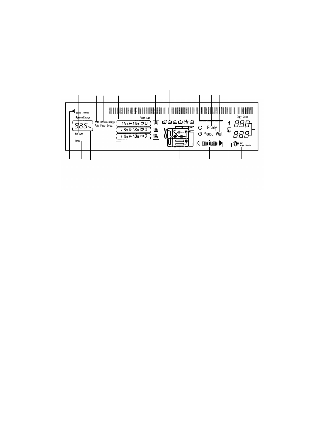
2.2 OPERATION PANEL
2.2.1 Keys and Indicators for Basic Functions
A4/A3 Version
34567
21 171820 19
16
1. Guidance Indicator
Lights when in guidance mode.
2. Guidance Key
Press to select guidance mod e.
3. Enter Key
Use to enter or change data in
selected modes.
4. Program Indicator
Lights when the copier is in user
program mode.
5. Program key
Press to input or recall user
program.
6. Timer Indicator
Lights when the mach ine has been
turned off by the weekly timer or
automatic shut-off timer.
15
14
12
891011
7. Timer Key
Press to operate the copier after it
has been turned off by the weekly
timer or automatic shut-off timer.
8. Clear Modes Key
Press to clear the copier of
previously entered settings and
modes.
9. Start Key
Press to start copying.
10. Interrupt key
Press to make interrupt copies
during a copy run.
11. Interrupt Indicator
Lights when interrupt mo de is
selected.
12. Clear/Stop Key
Press to cancel the copy number.
While copying press to stop
copying.
1-6
Page 8
LT/DLT Version
2
1
13
30 November 1990
34567
21 171820 19
16
13. Decimal Point Key
Use to input data for selected
modes.
14. Number Keys
Use to enter the desired number of
copies. They are also used to en te r
data for selected modes.
15.Auto Image Density Key
Press to select/cancel aut oma tic
image density mode.
16. Manual Image Density Keys
Use to cancel automatic control and
manually select the image density
level.
15
14
12
11
910
8
17. Auto Paper Select Key
Press to select/cance l aut o pa pe r
select mode.
18. Select Cassette Key
Press to select a cassette for paper
feed.
19. Full Size Key
Press to make the copy image s the
same size as these of the orig ina ls.
20. Enlarge Key
Press to make enlarged copies.
21. Reduce Key
Press to make reduced cop ies.
1-7
Page 9
17
30 November 1990
2.2.2 Keys and Indicator for Special/Optional Functions
A4/A3 Version
56
7
8
910111213
4
3
14
1
2
1. Staple Key
Press to select one of three staple
modes. (Optional recycling
document handler and finisher are
required.)
2. Staple Indicators
Show which staple mode is
selected.
3. Sorter Key
Press to select sort or stack mode.
(Optional sorter, or finishe r and
recycling document handler are
required.)
4. Stack Indicator
Lights when in stack mode.
5. Sort Indicator
Lights when in sort mode.
6. Duplex Indicators
Show which duplex mode is
selected.
22
23 21
7. Duplex Key
Press to select one of three duplex
modes.
8. Margin Adjustment Indicator
Lights when margin adjust men t
mode is selected.
9. Margin Adjustment Key
Press to set the margin on copy.
10. Centering lndicator
Lights when cente ring mode is
selected.
11. Centering Key
Press to vertically center an original
image on a copy.
12. Size Magnification Indicator
Lights when size magnificat ion
mode is selected.
20
19
18
16
15
1-8
Page 10
LT/DLT version
3
4
567
30 November 1990
8
910111213 14
12
13. Size Magnification Key
Press to select size magnification
mode.
14. Zoom Up Key
Press to increase the rep rod uction
ratio in 1% steps.
15. Zoom Down Key
Press to reduce the reproduction
ratio in 1% steps.
16. Auto Reduce/Enlarge Key
Press to select auto reduce /enlarge
mode.
17. Auto Reduce/Enlarge
Indicator
Lights when auto redu ce/enlarge
mode is selected.
18. Edit Image Key
Press to select one of three edit
image modes.
22
23 21
20
19
17
151618
19. Edit Image Indicators
Show which edit image mode is
selected.
20. Series Copies Key
Press to make copies from book
originals or 2-sided originals.
21. Series Copies Indicators
Show which series copies mode is
selected.
22. Cover Insertion Key
Press to select cover insertion
mode. (Optional document feeder
and sorter, or recycling document
handler and finisher are require d. )
23. Cover Insertion Indicators
Show which cover insertion mode is
selected.
1-9
Page 11
15
17
30 November 1990
2.2.3 Indicator Screen
A4/A3 version
1234 5678910111213 14
1. Full Size Indicator
Lights when full size mode is selected.
2. Auto Paper Select Indicator
Lights when auto pap er sele ct
mode is selected.
3. Auto Reduce/Enlarge Indicator
Lights when auto redu ce/enlarge
mode is selected.
4. Paper Size Indicators
Show the size and direction of the
paper.
5. Paper Volume Indicators
When the amount of paper remaining in cassettes.
6, Used Toner Bottle Indicator
Lights when the use d toner bottle is
full. Call your service representative.
16
181920212223
7. Add Toner Indicator
Blinks when it is time to change the
toner bottle. When it is continuously
lit, the copier cannot be used until a
new bottle is installed.
8. Add Staple Indicator
Lights when the staple cartridge
runs out of staples.
9. Add Oil Indicator
Lights when the silicone oil level
gets too low. Add silicone oil to the
bottle.
10. Check Paper Path Indicator
Lights if there is a misfeed within
the machine.
11. Load Paper Indicator
Lights when the cassette or tray in
use runs out of paper.
1-10
Page 12
LT/DLT version
15
17
18
1234 56
7
91011
8
12 1314
1920212223
30 November 1990
16
12. Copy Cycle Indicator
Displays the stage of the copy cycle
in progress.
13. Ready Indicator
Lights when the mach ine is ready to
make copies.
14. Wait Indicator
Lights when the mach ine is not
ready to copy.
15. Call Service Indicator
Lights when there is a funct ional
problem within the machine . Call
your service representative .
16. Copy Counter
(Upper) Displays the number of
copies entered.
(Lower) While copying, it sho ws the
number of copies made.
17. Auto Image Density Indica tor
Lights when the copier is
automatically controlling the image
density.
18. By-pass Feed Indicator
Lights when the by-pass feed table
is open.
19. Manual Image Density
Indicator
Shows the manually selected image
density.
20. Misfeed Location Display
Shows the location(s) of misfed
paper.
21. Magnification Ratio Indicator
Shows the selected rep rod uction
ratio.
22. Zoom Indicator
Lights when in zoom mode.
23. Special Features Indic ator
Lights when special/optional
function is selected.
1-11
Page 13
DEVELOPMENT
30 November 1990
3. COPY PROCESSES AROUND THE DRUM
EXPOSURE
DRUM CHARGE
QUENCHING
CLEANING
PRE-CLEANING
PAPER SEPARATION
ERASE
PRE-TRANSFER
LAMP (PTL)
IMAGE TRANSFER
DRUM CHARGE
In the dark, the charge corona unit gives a uniform positive charge to the
selenium drum. The charge rema ins on the surface of the drum because the
photo conductive seleniu m has ele ctrical resistance in the dark.
EXPOSURE
An image of the original is reflected to the selenium drum surface via the
optics assembly. The charge on the drum surface is dissipated in direct
proportion to the intensity of the reflected light, thus producing an elect rical
latent image on the drum surface.
ERASE
The erase lamp illuminates the areas of th e cha rge d dru m su rfa ce th at will
not be used for the copy image. The resistance of the drum in the illuminated
areas drops and the charge on those areas dissipates.
1-12
Page 14

30 November 1990
DEVELOPMENT
Negatively charged toner is attract ed to the positive ly charg ed area s of the
drum, thus developing the late nt image . (The negat ive tu rbo electric charge is
caused by friction between the carrier and toner pa rticle s.)
PRE-TRANSFER LAMP (PTL)
The PTL illuminates the drum to remove all positive charge from the exposed
areas of the drum. This prevents th e tone r particles from being reattracted to
the drum surface during paper separation and makes paper separation
easier.
IMAGE TRANSFER
Paper is fed to the drum surface at the prop er time so as to align the copy
paper and the develope d image on the drum surface. Then, a stron g po sitive
charge is applied to the back side of the copy pape r, pro viding an electrical
force which pulls the toner particles from the drum surface to the copy paper.
At the same time, the copy paper is electrically attracted to the drum surfa ce.
PAPER SEPARATI ON
A strong ac corona discharge is applied to the back side of the cop y pap er,
reducing the positive cha rge on the copy paper and breakin g th e electrical
attraction betwee n the paper and the drum. Then, th e stiffness of the copy
paper causes it to separate fro m the drum surf ace . The pick-off pawls help to
separate paper which has low stiffness.
PRE-CLEANING
The pre-cleaning corona (PCC) a pplies an ac coron a with a negat ive bia s to
the drum. This removes the positive cha rge from the drum and makes the
negative charge on the toner remaining on the dru m even .
CLEANING
The cleaning brush remo ves most of the toner on the drum and loosens the
remainder. Then, the bias roller, which has a positive potential, attracts the
toner particles from the cleaning brush to keep it clean. Finally, th e clea nin g
blade scrapes off th e loosened toner.
QUENCHING
The pre-quenching corona applies a positive corona cha rge to th e selenium
drum to eliminate any negative charge remainin g from t he pre-cle aning
corona. Then, light fro m the quench ing lamp electrically neutralizes the drum .
1-13
Page 15
30 November 1990
4. COPY CYCLE
RDH/ARDF
Lamp Stabilizer
Power Pack
PQC/CB
Finisher/Sorter
Sort
Stack
Staple
Q/PTL
QL (Cathode Tube)
Cleaning Unit
Pre-Cleaning
Corona
Power
Pack-PCC
Fusing Unit
Image
Fusing
Power Pack
PQC/CB
Pre-Quenching
Charge Unit
Cleaning
Transport Unit
Power Pack-C/B
Charge Corona Unit
Drum Charge
Quenching
PCC
Paper
Separation
Paper
Transport
Separation Corona
Exposure
Image
Transfer
Transfer Corona
Erase
Development
Toner Density
Detection
PTL
Original
Feed-in
Optics Assembly
ID Sensor Pattern
VL sensor Pattern
Erase Lamp Unit
Development Unit
Image Density
Sensor
PTL
(Cold Cathode Tube)
Registration
Registration Roller
Original
Stacking
Original
Positioning
Original
Auto-ID Sensor
Power Pack-C/B
Toner Supply
Mechanism
Lamp Stabilizer
Q/PTL
1st
Paper Feed
Original
Feed-out
Original
Density
Detection
Original
Inversion
Manual
Feed Table
Large
Capacity
Tray
Inverter
Mechanism
Inversion
Duplex Transport Unit
Duplex
Transport
Fork Gate Unit
Power Pack-T/S
Delivery Tray
Duplex
Stacking
1-14
Jogger Unit
Duplex Paper
Feed
Cassette Bank
2nd
Paper Feed
3rd
Paper Feed
Cassette
Cassette
Page 16
30 November 1990
5. MECHANICAL COMPONENT LAYOUT
3
2
1
28
27
26
4
5 6 7 8109
11 12 13 14 15
16
17
18
19
20
21
22
23
24
1. Inverter Unit
2. Third Mirror
3. Second Mirror
4. First Mirror
5. Exposure Lamp
6. Fusing Unit
7. Transport Unit
8. Lens
9. Cleaning Unit
10. Quenching Unit
11. Charge Corona Unit
12. Drum
13. Toner Shield Glass
14. Sixth Mirror
25
15. Erase Lamp Unit
16. Fourth Mirror
17. Fifth Mirror
18. Toner Tank
19. Manual Feed Table
20. Development Unit
21. Large Capacity Tray
22. T/ S Corona Unit
23. Jogger Unit
24. Third Cassette
25. Second Cassette
26. Duplex Delivery Tray
27. Fork Gate Unit
28. Duplex Transport Unit
1-15
Page 17
30 November 1990
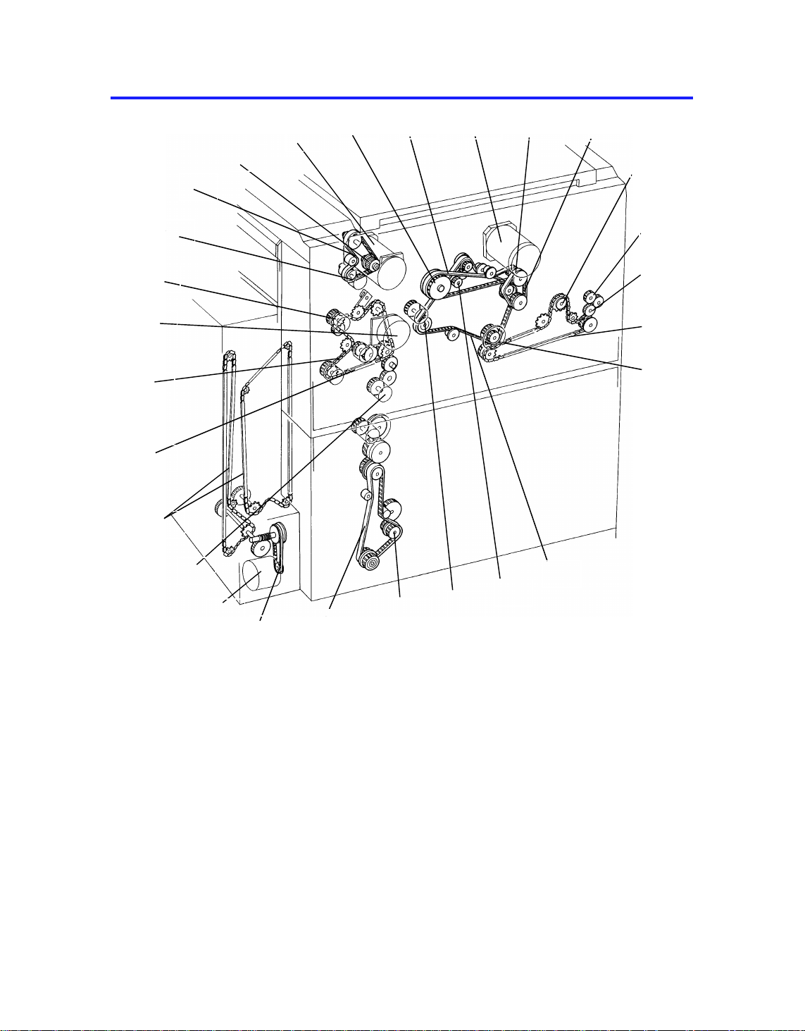
6. DRIVE LAYOUT
26
25
24
23
22
27
3
4
2
1
5 6
7
8
9
10
11
12
13
21
20
19
1. Development Drive Belt
2. Development Drive Gear
3. Development Motor
4. Drum Drive Pulley
5. Drum Drive Belt
6. Main Motor
7. Fusing/Duplex Drive Gear
8. Main drive Belt
9. Exit relay Roller Drive Sprocket
10. Inverter Roller Drive Gear
11. Exit Roller Drive Gear
12. Exit Drive Chain
13. Pulse Generator Drive Pulley
18
14
17
16
14. Registration Roller Drive Belt
15. Cleaning Drive Gear
16. Registration Clutch
17. 3rd Paper Feed Drive Gear
18. Cassette Bank Drive Belt
19. LCT Bottom Plate Drive Belt
20. LCT Motor
21. Duplex Paper Feed Clutch
22. LCT Bottom Plate Drive Chains
23. Relay Roller Clutch
24. Paper Feed Drive Chain
25. Paper Feed Motor
26. 1st Paper Feed Clutch
27. Toner Supply Clutch
15
1-16
Page 18
21
30 November 1990
7. ELECTRICAL COMPONENT LAYOUT
23
22
1
20
19
5
4
3
2
18
6
7
8
9
10
11
12
13
14
17
1. Fusing Lamp
2. Fusing Thermistor
3. Thermofuse
4. Fusing Exhaust Fan Motor
5. Exposure Lamp
6. Optics Thermoswitch
7. Anticondensation Heater
8. Cleaning Heater
9. Charge Fan Motor
10. Cleaning Thermoswitch
11. Cooling Blower Motor
12. Development Cooling Fan Motor
13. Vacuum Fan Motor
15
16
14. LCT Down Switch
15. Total Counter
16. Drum Heater
17. SC Cleaner Motor
18. SC Cleaner Home Position
Sensor
19. CC Cleaner Motor
20. CC Cleaner Home Position
Sensor
21. Printer Connector (RS232C)
22. Oil End Se nsor
23. Main switch
1-17
Page 19
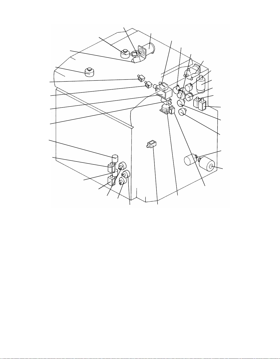
30 November 1990
25
26
27
28
29
30
31
32
55
54
53
52
51
50
24
49
48
47
46
45
33
34
35
36
37
38
39
40
41
42
43
44
24. 4th and 5th Mirror Drive Motor
25. Junction Gate Sol.
26. Lens Drive Motor
27. Inverter Pressure Sol.
28. Main Motor
29. Pick-off Sol.
30. Registration MC
31. Paper Feed Motor
32. Development Motor
33. Toner Supply MC
34. Scanner Drive Motor
35. 1st Paper Feed MC
36. 1st Pick-up Sol.
37. Manual Feed Pick-up Sol.
38. 1st Feed Relay MC
39. Duplex Paper Feed MC
40. Cassette Bank Drive Motor
41. LCT Motor
42. Duplex Positioning Roller Sol.
43. Jogger Motor
44. Duplex Stopper Sol.
45. 2nd Feed Relay MC
46. 3rd Paper Feed MC
47. 2nd Paper Feed MC
48. 3rd Pick-up Sol.
49. 3rd Lift Motor
50. 2nd Pick-up Sol.
51. 2nd Lift Motor
52. Duplex Pick-up Sol.
53. Cleaning Sol.
54. Fork Gate Sol. 2
55. Fork Gate Sol. 1
1-18
Page 20
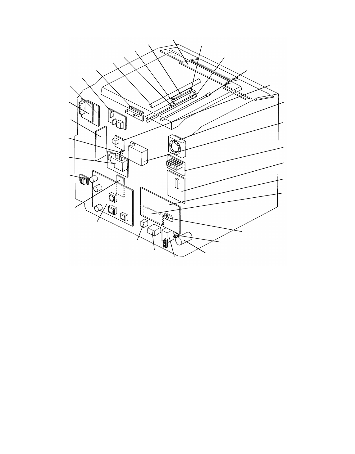
30 November 1990
85
84
83
82
81
86
80
56
57
58
59
60
61
62
63
64
65
66
67
68
69
70
71
72
79
78
56. Power Pack-CC/Bias
57. Power Pack-PQC/Cleaning
Bias
58. Erase Lamp
59. Bias Thermister
60. Drum Thermister
61. Registration Sensor
62. Operation Panel PCB
63. Image Density Sensor PCB
64. Pre-transter Lamp
65. Quenching Lamp
66. PTL/QL Stabilizer
67. Fusing Cooling Fan
68. Power Pack-PCC
69. Main Motor PCB
70. Optics PCB
77
73
74
75
76
71. Main PCB
72. AC Drive PCB
73. Memory Board
74. Circuit Breaker
75. Noise Filter
76. Main Transformer
77. Power Relay
78. Condition Relay
79. DC Power Supply PCB
80. Cassette Bank PCB
81. SSR PCB
82. Power Pack-T/S
83. Toner Overflow Sensor
84. Paper Feed PCB
85. Development Motor PCB
86. Paper Feed Motor PCB
1-19
Page 21
105
30 November 1990
90
89
88
87
126
125
124
123
122
121
120
119
118
117
116
115
114
113
112
87. Original Width Sensor
88. Original Length Sensor
89. Auto Density Sensor
90. Fork Gate Unit Safety Switch
91. Lens Home Position Sensor
92. Scanner Home Position Sensor
93. Scanner VL Position Sensor
94. 4th/5th Mirror Home
Position Sensor
95. Duplex Entrance Sensor
96. Toner End Sensor
97. 1st Lift Sensor
98. Jogger Home Position Sensor
99. 1st Relay Sensor
100. LCT Cover Sensor
101. LCT Cover Switch
102. 1st Paper Volume
103. LCT Lower Limit Sensor
104. Paper Position Sensor
105. LCT Lower Limit Safety Switch
91
92
93
94
95
96
97
98
99
104
106
107
108
109
110
111
106. 3rd Relay Sensor
107. 2nd Paper Volume Sensor
108. 3rd Paper Volume Sensor
109. 3rd Paper End Sensor
110. 2nd Paper End Sensor
111. 3rd Paper Size Sensor
112. 2nd Paper Size Sensor
113. 2nd Relay Sensor
114. Manu al Fee d Sensor
115. 3rd Lift Sensor
116. 2nd Lift Sensor
117. 1st Paper End Sensor
118. Manual Paper End Sensor
119. Duplex Paper Sensor
120. Pulse Generator
121. Transport Unit Safety Swit ch
122. Front Door Safety Switch
123. Exit Sensor
124. Fusing Exit Sensor
125. Exit Relay Sensor
126. Inverter Exit Sensor
100
101
102
103
1-20
Page 22

30 November 1990
8. ELECTRICAL COMPONENT DESCRIPTIONS
MOTORS
NAME FUNCTION LOCATION
Main Drives the main unit components. 28
Development Drives the development unit. 32
Paper Feed Drives the feed sectio n. 31
Development
Cooling Fan
Fusing Exhaust
Fan
Fusing Cooling Removes heat from around the fusing unit. 67
Cooling Blower Prevents build up of hot air in the optics
Vacuum Fan Provides suction so paper is held firmly on
Scanner Drive Drives the scanner. (dc servo) 34
Lens Drive Positions the lens. (dc stepper) 26
4th / 5th Mirror
Drive
Jogger Drives the jogger plates to keep paper
Cleaner Motors Clean charge and separation wires. 17, 19
Charge Fan Ensures even charge on the surface of the
LCT Rises and lowers the LCT bottom plate.
Cassette Bank
Drive
Lift Motors Lift paper to the appropriate feed position. 49, 51
Blows air to the developme nt unit bottom
plate.
Removes heat from around th e fu sing unit. 4
cavity.
the transport belt.
Positions the 4th/5t h mirror assembly. (dc
stepper)
evenly stacked on the duple x t ray.
drum.
(ac motor)
Drives the 2nd/3rd paper feed sections. 40
12
11
13
24
43
9
41
MAGNETIC CLUTCHES
NAME FUNCTION LOCATION
Registration Drives the reg istra tio n rolle r 30
Paper Feed
Clutches
Feed Relay
Clutches
Duplex Paper
Feed
Toner Supply Drives toner supply roller. 33
Starts paper feed from each feed stat ion. 35, 96, 47
Drives the relay rollers. 38, 45
Feeds paper from the duplex tray. 39
1-21
Page 23

30 November 1990
SOLENOIDS
NAME FUNCTION LOCATION
Cleaning Moves the clean ing blade against the drum. 53
Pick-off Moves the pick-off pawls against the drum. 29
Junction Gate Energizes to direct copies to the duple x tray. 25
Fork Gate
Solenoids
In unison, open and close the appropriate
fork gates according to pap er size.
54, 55
Duplex Pick-up Start s fee d from duplex an d aids the
stopper solenoid.
Duplex
Lowers positioning roller. 42
Positioning
Inverter Pressure Controls the inverter pressure roller. 27
Duplex Stopper Stops copy in the jogger unit. 44
Pick-up
Picks paper up from each feed sta tio n. 36, 48, 50
Solenoids
Manual Feed
Pick-up
Raises the pick-up roller when paper is fed
from the manual feed table.
52
37
SWITCHES
NAME FUNCTION LOCATION
Main Supplies power to the copier. 23
Front Door Safety Cuts ac power line. 122
Transport Unit
Cuts 24-volt lines. 121
Safety
Fork Gate Unit
Cuts 24-volt lines. 90
Safety
LCT Lower Limit
Cuts the signal line of the tray down. 105
Safety
LCT Down Lowers the LCT bottom plate. 14
LCT Cover Cuts power to the LCT when LCT cover is
101
opened.
SENSORS
NAME FUNCTION LOCATION
Pulse Generator Supplies timing pulses to the main board. 120
Exit Detects misfeeds. 123
Exit Relay Detects misfeeds. 125
Oil End Detects the low oil condition. 22
Toner Overflow Det ect s when the used ton er bo tt le is full. 83
Toner End Detects when it is time to add toner. 96
Registration Detects misfeeds. 61
1-22
Page 24

30 November 1990
NAME FUNCTION LOCATION
Manual Feed Detects when the manual feed table is open. 114
Scanner Home
Position
Lens Home
Position
4th/5th Mirror
Home Position
Paper Size
Informs the CPU when the scanner is at the
92
home position.
Informs the CPU when the lens is at the full
91
size position.
Informs the CPU when the 4th / 5th mirror
94
assembly is at the full size position.
Detects the paper size in the cassette. 111, 112
Sensors
Paper End
Sensors
Scanner VL
Position
Informs the CPU when the copy paper runs
out.
Informs the CPU when the scanner reaches
the VL pattern sensing position.
109, 110,
117
93
Relay Sensors Detects misfeeds. 99, 106,
113
Jogger Home
Position
Duplex Paper Detects whether or not paper is in the
Informs the CPU when the jogger plates are
at the home position.
98
119
duplex tray.
Duplex Entrance Misfeed detector 95
Auto Density Senses the background density of the
89
original.
Original Width Detects the original width. 87
Original Length Detects the original length. 88
Charge Cleaner
Home Position
Informs the CPU when the charge wire
cleaner has reached home po sitio n.
18, 20
Sensors
Manual Feed
Paper End
Informs the CPU that there is no paper in
the manual feed tray.
118
Fusing Exit Detects misfeeds. 124
Inverter Exit Detects misfeeds. 126
Lift Sensors Detects whether paper has been raised to
the proper paper feed position.
LCT Cover Informs the CPU when the LCT cover is
97, 115,
116
100
closed.
LCT Lower Limit Informs the CPU when the LCt bottom plate
103
reaches the lower limit position.
Paper Position Detects the paper position. 104
Paper Volume Detects the amount of paper in
LCT/cassettes.
102, 107,
108
1-23
Page 25

30 November 1990
THERMISTORS
NAME FUNCTION LOCATION
Drum Monitors the temp era tu re around the drum
and controls the rest-time comp ensation.
Bias Monitors the temperature aroun d the drum
and controls developmen t rest time bia s
compensation.
Fusing Monitors the fusing temperature and turns
the fusing lamp on/off.
POWER PACKS/STABILIZER
NAME FUNCTION LOCATION
Power Pack - T/S Provides high voltage for th e T/S coronas. 82
Power Pack CC/Bias
Power Pack PQC/Cleaning
Power Pack PCC
Provides high voltage for the charge corona
and the development roller bias.
Provides high voltage for the quenching
corona and the cleaning bias roller.
Provides high voltage for the pre-cleaning
corona.
PTL/QL Stabilizer Provides high voltage for the quenching
and pre-transfer lamps.
60
59
2
56
57
68
66
HEATERS
NAME FUNCTION LOCATION
Drum Warms the drum when the main switch is
off.
Cleaning Warms the cleaning section when the main
switch is off.
Anticondensation Prevents moisture from forming on the
optics.
THERMOSWITCHES
NAME FUNCTION LOCATIO N
Optics Provides overheat protection in the optics
unit.
Cleaning Provides overheat pro te ctio n in the
cleaning unit.
16
8
7
6
10
1-24
Page 26

30 November 1990
LAMPS
NAME FUNCTION LOCATION
Exposure Applies high intensity light to the original for
exposure.
Fusing Provides heat to the fusing unit. 1
Erase Discharges the drum outside the image
58
area. Erases lead/trail edge.
Quenching Neutralizes any charge remaining on the
65
drum surface after cleaning.
Pre-transfer Reduces charge on the drum surface
64
before transfer.
PRINTED CIRCUIT BOARDS
NAME FUNCTION LOCATION
Main Controls all copier functions both directly
71
and through other PCB s.
Optics Controls the speed of the scanner, the
70
position of the lens, and the position of the
mirrors.
Operation Panel Contro ls the LED mat rix, and mon ito rs the
62
key matrix.
Main Motor Controls the speed of the main motor. 69
Development
Motor
Paper Feed Motor Controls the speed of the paper feed drive
Controls the speed of the development
motor.
85
86
motor.
Paper Feed Interfaces with overall pap er fe ed ; rece ives
84
input from paper size and paper end
sensors.
DC Power Supply Rectifies 100 Vac input and outputs dc
79
voltages.
Image Density Detects the density of the image on the
63
drum.
Cassette Bank Interfaces with overa ll cassette bank drive. 80
AC Drive Drives the exposure lamp and the fusing
72
lamp.
Memory Controls weekly timer and memory
73
functions.
SSR Switches the LCT bottom plate up/down 81
5
1-25
Page 27

30 November 1990
OTHERS
NAME FUNCTION LOCATION
Circuit Breaker G uards against voltage surges in the input
power.
Main Transformer Steps down the wall voltage to 100 Vac. 76
Thermofuse Provides back-up overheat protection in the
fusing unit.
Total Counter Keeps track of the total number of cop ies
made.
Power Relay Controls main power. 77
Condition Relay Controls the heaters on/off. 78
Noise Filter Removes electrical noise. 75
Printer Connector Used for connection to the printer
(RS 232C serial interface).
74
3
15
21
1-26
Page 28
9. OVERALL MACHINE CONTROL
30 November 1990
Pulse Generator
Sensors
-Toner Overflow
-Exit
-Inverter Exit
-Duplex entrance
-Duplex Paper
-Jogger H.P.
-Toner End
-Oil End
-Image Density
Solenoids
-Fork Gate
-Inverter Return
-Junction Gate
-Duplex Positioning
-Duplex Stopper
-Duplex Pick-up
-Pick-off
-Cleaning
Magnetic Clutches
-Duplex Paper Feed
-Toner Supply
Motors
-Jogger
-Vacuum Fan
-Fusing Exhaust
-Charge Fan
-Development
Cooling Fan
-Ozon Fan
Counters
-Total
-Key
-A3/LDG
Erase Lamp
Power Packs
-PQC/Cleaning Bias
-CC/Development
Blas
Quenching Lamp
Stabilizer
ARDF/Sorter
RDH/Finisher
Menu Sheet Reader
RS232C Interface
Main PCB
Optics PCB
Main Motor
Development
Motor PCB
Paper Feed
Motor PCB
AC Drive
Operation
Panel PCB
Paper Feed
Casstte Bank
(2nd/3rd Feed)
PCB
PCB
PCB
PCB
Motors
-Scanner Drive
-Lens Drive
-4th/5th Mirror Drive
-CC Cleaner Motor
-SC Cleaner Motor
Sensors
-Scanner Home Position
-Scanner Overrun
-Lens H.P.
-4th/5th Mirror H.P.
-CC Cleaner H.P.
-SC Cleaner H.P.
Main Motor
Development
Motor
Paper Feed
Motor
Exposure Lamp
Fusing Lamp
Sensors
-Registration
-1st Relay
-Manual Feed
-Manual Feed Paper End
-Paper End
-Lift
-Paper Volume
Solenoids
-Manual Feed
-Pick-up
Magnetic Clutch
-Paper Feed
-Relay
Sensors
-Paper End (2)
-Paper Volume (2)
-Paper Size (2)
-Lift Relay (2)
Moters
-Lift (2)
Solenoids
-Pick-up (2)
Magnetic Clutch
-Paper Feed (2)
-Relay
1-27
Page 29
30 November 1990
10. AC AND DC POWER DISTRI BUTI ON
AC Power
Main Motor PCB
Dev. Motor PCB
Paper Feed Motor
Optics PCB
Main PCB
Paper Feed PCB
Clutches
Motors
Solenoids
Counters
Relays
Operation Panel
Power Packs
Erase Unit
PCB
PCB
5V (VC)
24V (VM)
24V (VA)
24V (VP)
DC
Power
Supply
5V (VC)
24V (VF)
24V (VA)
AC Drive
PCB
Cassette Bank
(2nd /3rd Feed)
ARDF/RDF
Finisher
Sorter
Menu Reader
Transformer
Fusing Lamp
Exp Lamp
Drum Heater
Anticondensation
Heater
Cleaning Heater
The illustration on this page shows the electrical power dist ribution in block
form.
AC power (115/220 volts) is supplied from the wall outlet directly to the fusing
lamp and the step-down tran sfo rmer. The transformer supplies 100 volts ac
to the power supply unit, the ac drive board , the pa per ban k (2nd /3 rd pa per
feed station)and sorter.
The power supply unit produ ces fo ur 24 volts an d on e 5 volt s t o operate the
PCB’s, the clutches, the moto rs, the solenoids, the counters, th e rela ys, the
power packs and the era se unit.
1-28
Page 30

SECTION 2
SECTIONAL DESCRIPTION
Page 31

30 November 1990
1. DRUM
1.1 SELENIUM DRUM CHARACTERISTICS
Selenium has the following charact erist ics:
• Accepts a high positive electrical charge in the dark. (The ele ctrical
resistance of selenium is high in the abse nce of ligh t.)
• Dissipates the electrical charge when exposed to lig ht. (Exposure to light
greatly enhances the condu ctivit y of sele nium.)
• Dissipates the electrical charge in direct proportion to the intensit y of the
light.
That is, where stronger light is direct ed to the selenium surface, a smaller
voltage remains on the selenium.
The sensitivity of selenium chan ge s slight ly wit h varia tions in the surface
temperature of the drum. (Unde r cool con ditions, the drum conductivity
decreases. This will result in background or excessive image density.) As a
countermeasure, the development bias is change d to compensate for
temperature varia tio ns around the drum. Also, while the copie r is of f, the
drum heater warms the drum.
Drum sensitivity also depends on how long the drum has rested between
copy runs. The copier’s CPU compe nsa te s fo r cha ng es in dru m sensitivity
due to rest time by changing the deve lop men t bia s. This prevents variations
in image density at the beginning of copy runs.
The selenium drum used in th is mode l has hig h sen sitivity, good color
reproduction, and good rep rod uction of low contrast originals (pen cil
originals, etc.)
2-1
Page 32

30 November 1990
1.2 DRUM HEATER CONTROL
AC Power
Transformer
100VAC
Thermo
Switch
Drum Heater
Anticondensation
Heater
Cleaning Heater
RA2
Main Switch
The drum heater receives 100 volts ac only when the main switch is turned
off. When the main switch is turned on, the 100 volt ac current stop s flowin g.
2-2
Page 33

2. DRUM CHARGE
2.1 OVERVIEW
[B]
30 November 1990
[A]
[C]
[D]
This copier uses a dual wire corotron un it and a highly sensitive selenium
drum. The corona wires [A] generate a flow of positive ions when the charge
power pack applies a high positive volt ag e to the coron a unit. The drum
coating [B] receive s a unif orm po sitive charge as it rotates past the corona
unit.
The charge fan [C] provides a smooth flow of air to the interior of the charge
corona unit [D] to prevent un eve n build up of positive ions. (An uneven build
up of positive ions could cause uneven image density.)
2-3
Page 34

30 November 1990
2.2 WIRE CLEANER
[B]
[A]
[B]
[A]
[D]
[C]
Paper dust or toner particles on the coron a wires [A ] may interfere with
charging. The wire cleaner [B] corrects this problem by automatically wiping
the charge corona wires clean. Pa ds on the wire clean er bra cket clean the
corona wires as the dc motor [C] drives th e cleaner bracket from the home
position to the rear e nd of th e coro na unit and the n back a gain.
Operation of the wire cleane r is based on copy coun t. A RAM co unter keeps
track of the number of copies made since the last time the wires were
cleaned. The CPU checks this counte r each time th e cop ier is turn ed on. If
the count is greater than 5,000 at that time , th e CPU tu rns on the clean er
motor to clean the coro na wire s. Simu ltaneously, it resets the count er to zero.
During a cleaning cycle, the clea ne r motor drives the wire cleaner toward the
rear endblock. After 30 seconds, the motor reverses to drive the wire cleaner
to the home position. Normally, the cleaner reache s the rear en dblock in
about 10 seconds, but th e mot or stays on for 20 seconds to ensure that the
cleaner moves the full distan ce. Th e mot or turns off when the cleaner
activates the home position sensor [D].
2-4
Page 35

2.3 WIRE CLEANER MOTOR
30 November 1990
Optics PCB
C
P
U
Driver
Driver
( 5)
( 5)
( 5)
( 5)
( 5)
( 5)
CN306-1
CN306-4
CN306-5
CN306-6
CN306-7
CN306-2
REV
FWD
REV
FWD
5V(Vc)
CC
Cleaner
H.P.
Sensor
C C
M
SC
M
5V(Vc)
SC
Cleaner
H.P.
Sensor
Small dc motor in the corona fron t end block drives the corona wire cleaner.
When a cleaner motor is energized, the CPU supplies forward drive for 30
seconds from CN306-4. Then , it reve rses th e po larit y of the motor drive
voltage to return the coron a wire clea ne r to th e ho me position (CN306-5).
When the home position senso r t urn s o n, the CN306 -1 dro ps to zero and it
stops.
This mechanism is used also for the sepa rat ion corona wire cleaner.
If the home position sensor is not activate d with in 20 secon ds af te r reverse
drive is initiated, the CPU stops the moto r and adds 1 to the cou nt er stored in
SP mode 121. Copies can still be made and there is n o service call indica tion
on the opera tio n panel.
SP #121 SC 85: C.C. Home Position Sensor does not turns on .
SC 86: C.C. Home Position Sensor do es not turns off.
SC 87: S.C. Home Position Sensor does not turns on.
SC 88: S.C. Home Position Sensor does not turns off.
2-5
Page 36

30 November 1990
2.4 CHARGE CORONA POWER PACK
+24V(Vp)
Front Door Safety SW
CC/Bias P.P
CN1-1
CN1-5
DC/DC
Converter
Main PCB
Charge( 5)
5V DC
CN2-3
CN102-B18
CN2-5
TC/SC P.P.
( 24)
P-GND
CN1-2
CN1-1
The circuit operation for the charge corona begins with the input of +5 volts
(Vc) at CN2-3. This voltage powers the LED of the photocoupler.
Additionally, 24 volts (Vp) enters the power pack at CN1-1. This po wer sup ply
is used to produce the high vo lta ge corona. This voltage is interrupt ed if the
front door safety switch opens.
The charge corona turns on 543 milliseconds before the registration MC is
turned on. A LOW signal from the CP U (CN101 -B1 8) is sent to the CC/B
power pack through the TC/SC po wer pa ck.
The OFF timing of the charg e coro na powe r pack varies according to the
paper size being used.
2-6
Page 37

3. OPTICS
3.1 OVERVIEW
30 November 1990
[C]
[B]
[A]
[D]
[I]
During the copy cycle, an image of the origin al is refle cted onto the surface of
the drum [I] via the optics assembly. The op tics asse mbly con sists of the
following parts:
1. First Scanner [A]:
Exposure lamp [B] (85 V, 160 W )
First mirror
AD (Auto Density) sensor fiber optics cable [C]
2. Second Scanne r [ D]:
Second mirror
Third mirror
3. Lens (F5, f = 215 mm) [E]
[E]
[F]
[G]
[H]
4. Fourth and Fifth Mirror Assembly [F]:
Fourth Mirror
Fifth Mirror
5. Sixth Mirror [G]:
6. Toner Shield Glass [H]
2-7
Page 38

30 November 1990
This copier has nine stand ard reproduction ratios: five red uctions, three
enlargements and full size. In additio n, it has a zoom fun ctio n. The
reproduction ratio can be selected in one percent ste ps fro m 60% to 15 5% .
A servomotor drives the first and secon d scanners during the copy cycle.
This motor is controlled by the opt ics PCB, which changes the motor speed
depending on the reproduction ratio. Two stepper motors chan ge the posit ion
of the lens and the fourth and fifth mirror assembly to change the
reproduction ratio. The sixth mirror is fixe d.
The fiber optic cable used for the auto density sensor (ADS) is mounted on
the first scanner. The ADS collects ligh t ref lected from the original in auto
density sensing mode.
2-8
Page 39

3.2 EXPOSURE LAMP CONTROL
Optics PCB
E
Feed back signal
CPU
24V
C
B
0V
0V
Trigger Pulse
CN303-2
CN303-1
CN303-4
CN303-3
CN304-4
CN303-9
CN501-2
CN501-1
CN501-4
CN501-3
CN501-9
CN501-6
AC Drive PCB
Zero
Cross
Detect
Lamp
Monitor
Lamp Control
CN503-1
CN503-2
A
CN503-3
CN503-5
D
30 November 1990
Front
Door
Safety
Switch
RA1
AC (N)
AC (H)
TH. Switch
Exposure Lamp
AC power
Zero cross
Trigger pulse
Lamp power
Feedback
signal
A
B
C
D
E
Feedback
The optics board controls and mon ito rs t he expo sure lamp circuit, instead of
the main board. The ac drive board receives 100 volts ac from the
transformer [A] and it is used for th e zero cross signal, which is sent to the
optics board [B]. The optics board sends the lamp trigger pulses to the ac
drive board from CN303-9 [C]. This lamp trig ger pulse activa te s the triac on
the ac drive board, which provides th e ac power to the exposure lamp [D].
The voltage applied to the expo sure lamp is also provided to the lamp
monitor circuit, which rectif ies and smoothes it.
The main CPU monitors the lowe st po int of th is smoot he d wave (f eedb ack
signal) which is directly proport ion al to the actu al lamp voltage, and then
changes the timing of th e trig ge r pulse in response to the feed ba ck volta ge .
If the lamp voltage is too low, the main CPU sends the trigger pulse earlier,
so that more ac power can be app lied to th e exposure lamp. This feedback
control is performed instantly; so the lamp voltage is always stable even
under fluctuating as power conditions.
The voltage applied to the expo sure lamp can be changed with SP mo de #48
and displayed with sp mode #5 1.
2-9
Page 40

30 November 1990
3.3 SCANNER DRIVE
[D]
[B]
[A]
[E]
This model uses a dc servomotor [A ] to drive the first [B] and second [C]
scanners.
[C]
This first scanner is attached to the scanner drive wire by the wire clamp [D].
The second scanner is connected to the scanner drive wire by a movable
pulley [E] (the second scanner pulley).
The second scanner pulley move s the second scanner at half the velocity of
the first scanner. This maintains th e focal distance between the original and
the lens during scanning. This rela tio nship can be expressed as follows:
V1r = 2(V2r) = VD/r
where r: Reproduction
V1r: First Scanner Velocity (when the Reproduction ratio is "r")
V2r: Second Scanner Velocity (when the Reproduction ratio is "r")
VD: Drum Peripheral Velo city (30 0 mm/s)
The first scanner wire clamp also actuat es the home position sensor. The
CPU on the optics board controls both the registration and return timing.
2-10
Page 41

3.4 SCANNER MOTOR CONTROL
Scanner Home Sensor
24V(VM)
30 November 1990
M-GND
Timing Pulse
Reset
5V(VC)
C-GND
Main PCB
CN307-1
CN302-5
CN302-4
CN302-7
CN302-3
CN302-2
CN302-8
CN302-9
5V
TXD
RXD
LE
S/R
RST
-2
-3
Optics CPU
Speed data
CN304-1
F
R
Optics PCB
Driver
Timer IC
PWM
CN304-2
E-A
E-B
CN308-1
CN308-3
CN301-1
CN301-2
CN301-3
CN301-4
Scanner drive
M
The scanner drive motor is a dc servomoto r. The CPU o n the op tics bo ard
controls the speed of this servomotor. The main CPU and the optics CPU
communicate through a serial interf ace bus (TXD/ RXD).
Encoder
After the main CPU sends the scann er sta rt signal to the optics CPU, the
optics CPU receives the drum speed data from the main PCB (pulse
generator).
An encoder on the servomotor has two magn et ic senso rs t hat ge nerate two
pulse signals. The optics CPU monit ors th e scan ne r spee d an d dire ctio n by
these pulse signals.
Based on the drum speed and encoder data, the optics CPU determines the
proper speed for the scan ner drive motor to obtain proper vertical
magnification. The optics CPU sends the spe ed data to the timer IC, which
controls the scanner moto r circu it.
The home position sensor informs the optics board when the first scanner is
in the home position.
2-11
Page 42

30 November 1990
3.5 LENS/MIRROR POSI TI O NING
[C]
[D]
[B]
[A]
Lens Drive
The lens drive motor (stepper mot or) [A ] cha ng es th e len s posit ion according
to the selected reproduction ratio to provide the prop er ho rizontal
magnification between the lens an d the dru m’s surface.
The output gear of the lens drive motor en gage s the gears [B] of th e lens
drive pulley. The lens drive wire [C] is wrapped around the lens drive pulley
and is connected to the lens drive bracket [D]. The rotation of the lens drive
pulley moves the lens back and forth in discrete steps.
2-12
Page 43

Lens Positioning
[A]
30 November 1990
[C]
[B]
[D]
[A] Lens Drive Pulley
[B] Lens Housing
The lens home position senso r [C] informs the optics PCB when the lens [D]
is at the full-size position (home position). The optics PCB determines the
lens stop position in reduct ion and enlargement modes by counting the
number of steps from the home position. When the repro duction ratio is
changed, the lens move s directly to the selected magnif icat ion position.
2-13
Page 44

30 November 1990
Operation
Panel
PCB
TXD/RXD
Main PCB
Home position is checked by
moving the lens from the
enlargement side towa rds the
reduction side. So, whe n ho me
position is checked, a LO W to
HIGH to LOW signal is present
at CN307-5 of the optics board.
This occurs when the actua to r
blade enters and exits the lens
home position sensor. The lens
only references home posit ion
when going to full size (at powe r
up, when modes are cleared,
when full size is selected.) The
lens always overshoots the
selected magnification ratio
position by 40 steps to eliminate
mechanical play when go ing
from enlargement to reduction.
RXD
TXD
Optics
CPU
Reduction
Optics PCB
Driver
5V(VC)
( 5)
Home Position (100%)
40pls
40pls
40pls
24V(VM)
CN305-2
CN305-3
CN305-4
CN305-5
CN305-1.6
CN307-1
CN307-5
CN307-2
M-GND
Lens motor
M
24V(VA)
Lens H.P. sensor
Enlargement
2-14
Page 45

3.6 FOURTH AND FIFTH MIRROR ASSEMBLY
[E]
[F]
30 November 1990
[B]
[D]
[C]
[A]
When the reproduction rat io is chan ged, the stepper motor [A] moves the
fourth and fifth mirror assembly [B ] usin g the wire [C] and pulleys [D]. This
provides the proper focal distance between the original and the drum.
When the fourth and fifth mirror assembly is in the full-size position, the
actuator [E] on the assembly actuates the fourth/fifth mirro r home posit ion
sensor [F]. This signal goes to the optics CPU.
2-15
Page 46

30 November 1990
Fourth and Fifth Mirror Assembly Positioning
Optics PCB
Operation
PCB
TXD/RXDPanel
Main PCB
RXD
TXD
Optics
CPU
Driver
24V(VM)
CN305-8
CN305-9
CN305-10
CN305-11
M-GND
CN305-7,12
24V(VM)
M
Mirror
Motor
High
Power up
Home
Position
Signal
Low (Reduction/Enlargenent)
40pls
100% Mag Ratio
(Home Position)
Power up
100%
40pls
Away from H.P.
Reduction
Towards H.P.
( 5)
5V
CN307-1
CN307-6
CN307-2
Mirror
Sensor
The mirror home position sensor informs the optics CPU when the fourt h and
fifth mirror assembly is at the home positio n. The ho me po sitio n is
determined by a LOW to HIGH to LOW change on CN307-6 of the optics
board.
When a reproduction rat io is se lect ed , the operation panel PCB sen ds th is
information to the main board. The main board th en send s the app rop riat e
trigger signals through the serial line to the optics board.
When moving away from the home posit ion, the mirror drive pulley turns
clockwise and moves directly to the sele cte d po sitio n. However, when
moving towards the home position (pulley turns counterclockwise), the mirror
assembly overshoots the selected position once and th en returns to the
selected position. This ta kes out an y mechanical play.
2-16
Page 47

30 November 1990
3.7 ORIGINAL SIZE DETECTION IN PLATE N MODE
[A]
[B]
There are seven reflective sen sors in the optics cavity for the original size
detection. Two of the m a re use d for sensing the original wid th [A] and the
other five sense the original len gt h [B ].
While the main switch is on, these sensors are active and the origin al size
data is always sent to the main cpu. Howe ver, the main CPU che cks the dat a
only twice when in platen mode.
2-17
Page 48

30 November 1990
1st Check
[A]
15 cm
15cm
2nd Check
P3 P4 P5 P6 P7
1st
Original Length
Sensor
ONONONONOFFONOFFONOFF
2nd
ON
First check is done when the pla te n po sition sensor [A] turns on. This is when
the platen is positioned about 15 cm above the expo sure glass. At th is time,
only the sensor(s) locate d unde rneath the original receive the reflected light
and are on. Other sensor(s) a re of f. Through the on/off data of th e seven
sensors, the main CPU can reco gn ize th e orig inal size.
Second check is done when th e platen cover is closed. (The plate n cover
switch is on.) This is to confirm that the original size detected at the first
check is correct. At the check, all senso rs shou ld be on becau se of the white
color of the platen shee t. This d ou ble check prevents mis-detection of the
original size due to a black solid area being positioned just above a sensor.
In case the copy is made with the open plat en condition, the main CPU
decides the origina l size only th rough the data when the Print key is p resse d.
No second check can be perf orme d.
This original size detection method eliminat es the necessit y for a pre -scan
and increases the machine ’s prod uctivity.
2-18
Page 49

3.8 VL DETECTION
Vsl ≈ 2.0
30 November 1990
[E]
Vsg ≈ 4.0
A: VL Position Sensor
B: VL Pattern
C: Right Scale
D: ID Sensor
E: VL Pattern Image
[D]
[C]
[B]
[A]
In order to compensate for cha ng es in th e cop y image density cau sed by
dirty optics, the main CPU checks the image density of the VL pattern when
the main switch is turned on. This is done only when the fusin g temperature
is lower than 100 °C.
After the machine idles for 30 seconds, the scanner moves un til the scanner
VL position sensor [A] tu rns on . The VL pattern [B] is located un de rne at h th e
right scale [C], about 30 mm from the scanner fu ll-return position. (At this
time, the lens also moves in th e red uction direction to prevent the scanner
guide from striking the lens.) Then, the VL patt ern is exposed.
The ID sensor [D] checks the reflectivity of the VL patt ern ima ge and the ID
sensor pattern image [E ] on the drum surf ace in the same way. The CPU
receives two voltage values dire ctly from the ID sensor: the value for t he bare
drum (Vsg) and the value for the pattern image (Vsl). The main CPU stores
Vdat (Vdat = Vsl/Vsg) in memory an d comp are s it with the VL reference
value (Vref). Vref was sto red in memory by SP mode #67 at machine
installation when the light intensity was adjusted.
2-19
Page 50

30 November 1990
(Vref Setting: SP mod e #6 7)
When SP mode #67 is set, the scann er move s t o th e VL pat te rn po sitio n. The
main CPU collects both Vsl and Vsg data and store s t hese values in memory
as the VL reference (Vref = Vsl/ Vsg ). This Vre f is st ore d in memo ry unt il the
next Vref setting is performed.
NOTE: P erform Vref setting after adju stin g the ligh t intensity or Vsg.
When the Vdat value is monitore d, a fixed bias (80 volts) is app lied to th e
development rollers; however, when Vref is set by SP mode #67, the
development bias is automatically shifted to 50 volts. This 30 volt differen ce
corresponds to one half step of the manual ID level.
If Vdat is less than Vref, th e exposure lamp voltage is increase d 2 volts. If
Vdat is greater than Vref, the volta ge is decrea sed 1 volt.
Vref ≥ Vdat Dark copy image (2 volts is incr ea se d.)
Vref < Vdat Light copy image (1 volt is decreased.)
At VL detection, the scan ne r moves to the VL sen sor position two times: The
first scan checks Vsl and Vsg for VL det ect ion and the second scan monitors
changes in the exposure lamp ligh t int en sity fo r ADS compensation.
2-20
Page 51

4. ERASE
30 November 1990
El
A
B
Lo
Lc
Es
ON
OFF
ON
Es
g
4.1 OVERVIEW
A: Lead Edge Erase Margin
B: Side Margins --- 2 ± 2 mm each (For full-size copies the total of
both side margins is less than 4 mm.)
Lo: Original Image Width
Lc: Charged Width on the Drum
El: Lead Edge Erase
Es: Side Erase
R: Paper Lead Edge Registration --- 0 ± 2 mm
A+R: Lead Edge Blank Margin --- 3.5 ± 2.5 mm
The erase unit consists of a PCB with 10 registe rs a nd a row of 80 LEDs
mounted in a plastic casing. The LEDs emit light in the yellow-gre en part of
the spectrum.
The erase lamp performs th e fo llowing functions: lead ed ge erase, side
erase, trail edge erase, ima ge dens ity pa tt ern [g], and the editing fu nct ions.
Trail edge erase begins after the trailing edge of the copy paper; therefore,
the trailing edge will not appear on the copy.
2-21
Page 52

30 November 1990
4.2 LEAD EDGE AND TRAILING EDGE ERASE
The entire bank of erase lamp s turns on to erase the drum before and after
the image area. Leading edge erase overlaps the paper an d the image
slightly. The leading edge marg in he lps pre ven t fusing jams by making it
easier for the stripper pawls to separate the paper from the hot roller. Trailing
edge erase turns on about 2 mm after the trailing edge of the copy paper.
The width of the lead edg e marg in can be ad just ed by SP mod e #4 1.
Mode No. Function Data
41 Lead Edge
Erase Margin
Adjustment
During image density detection cycles (once eve ry ten cycles), th e cen ter
block of erase lamps turns of f lon g en ou gh for th e sensor pattern to be developed [g].
Adjusts the
lead edge
margin
0 - 15 8
Factory
Setting
Comments
0.6mm per
step (max.
-4.8mm to
+4.2mm)
4.3 SIDE ERASE
Side erase overlaps the imag e sligh tly on eith er side . The CP U calcula tes the
side erase margins from the pap er size and the selected reproduction ratio.
As the paper is fed to the cen te r o f th e dru m , th e LEDs for side erase turn on
in pairs. The erase lamp is not used for side era se with A3 or 11 x 17 paper.
For these paper sizes, side erase occurs due to the end block covers of the
charge corona.
The CPU adjusts the side erase margin to be as near as possible to th e
actual image size, even wh en using the zoom function. Howe ver, since the
erase lamp LEDs will not work in precise one millimeter int erva ls, the side
erase margin varies slightly depend ing on th e rep rod uction ratio.
SP 27 increase the side margin s by 5 mm.
Also, the position of the entire erase lamp unit can be adjusted by turning an
adjustment screw at th e rear side of the unit.
This adjustment is neccessary wh en the side era se margins are uneven.
2-22
Page 53

4.4 EDGE ERASE FUNCTION
Edqe
Paper
size
A3
11"
B4
10"
8-1/2"
A4
8"
B5
A5
5-1/2"
B6
A6
Erase
1-3
78-80
1-6
78-80
74-80
1-13
68-80
1-15
66-80
1-16
65-80
1-20
61-80
1-26
55-80
1-27
54-80
1-28
53-80
1-30
51-80
1
80
1-7
5 mm
(0.2")
) 3.5mm
)4.7
)3.5
)4.5
)3
)5
)4.1
)3.5
)4
)4.85
)4
)2.5
79 -80
77-80
1-8
73-80
1-8
73-80
1-15
66-80
1-17
64-80
1-18
63-80
1-22
59-80
1-27
54-80
1-28
53-80
1-29
52-80
1-31
50-80
1-2
1-4
10 mm
(0.4")
)8.5mm
)9.7
)11
)9.5
)8
)10
)9.1
)8.5
)9
)9.85
)9
)7.5
1-3
78-80
1-6
75-80
1-9
72-80
1-10
71-80
1-17
64-80
1-19
62-80
1-20
61-80
1-24
57-80
1-28
53-80
1-29
52-80
1-30
51-80
1-32
49-80
15 mm
(0.6")
)13.5mm
)14.7
)13.5
)14.5
)13
)15
)14.1
)13.5
)14
)14.85
)14
)12.5
30 November 1990
20 mm
(0.8")
1-4
)18.5mm
77-80
1-8
)22.2
73-80
1-11
)18.5
70-80
1-12
)19.5
69-80
1-19
)18
62-80
1-21
)20
60-80
1-22
)19.1
59-80
1-26
)21
55-80
1-29
)19
52-80
1-30
)19.85
51-80
1-31
)19
50-80
1-33
)17.5
48-80
The edge erase function erases a border around the copy. The border is
adjustable in 4 steps using SP mode #38. These borders are approximately
5, 10, 15, and 20 millimeters wide, but vary slightly according to paper size
and the selected repro duction ratio. The table shows the ON/OFF condition
of the erase lamp LEDs for the various paper sizes. The factory setting is 10
millimeters.
2-23
Page 54

30 November 1990
4.5 ERASE LAMP CIRCUIT
LED
23456
IC 1
GND SI L R CK E VCC SO
78
9
LED
10 11 12
GND SI L R CK E VCC SO
CN37-F
CN37-6
CN37-A
CN37-1
CN37-5
CN37-2
CN37-3
CN37-4
IC 2
13
14
5V(VC)
C-GND
CLOCK
ENABLE
LATCH
ERASE DATA
15 16
B-GND
5V(VB)
73
LED
GND SI L R CK E VCC
CN102-B1
CN102-A16
CN102-B17
CN102-B18
CN102-A18
CN102-A17
This copier uses 80 LEDs in the era se lamp unit. The large number of LEDs
allows precise control of the side erase margins.
Shift register drivers contro l the LEDs. Init ially, the ENAB LE signal (LOW
active) sets all shift registers t o OFF. Th en the main board sends ERASE
DATA to the shift registers fro m CN1 02-A17.
74 75 76 77 78 79 80
IC 10
ERASE UNIT
MAIN BOARD PCB
After the ENABLE sign al goes ba ck to HIG H, th e shift registers start
accepting data. The dat a bit fo r LE D 1 is set at each CLOCK pulse. If the
data line is HIGH at the time of the CLOCK pulse, the shift regist er is set to
turn the LED on; if it is LOW, the shift register is set to keep the LED off. The
data in the shift registers is shifted right one positio n each clock pulse; so, it
takes 80 CLOCK pulses to set the shift registers for all the LE Ds.
After all data bits have been sent, th e main boa rd sen ds th e LATCH sig nal to
turn on the erase lamp unit. Simultaneously, the shift registers turn on all
LEDs for which data bits have been set.
To turn off the erase lamp unit, the ENABLE signal is reset to LOW.
2-24
Page 55

5. DEVELOPMENT
5.1 OVERVIEW
[D]
[E]
30 November 1990
[C]
This copier uses a double roller develop men t (DRD) system. This system
differs from single roller develo pment system in that (1) it develop s the image
in a narrower area, (2) it develops the image twice, and (3) the relative speed
of each development roller ag ain st the drum is reduced. Also, finer toner and
developer (smaller particle size) are used . Both DRD system and new
supplies improve the image, especially of thin horizont al line s, th e tra iling
edges of the half-tone areas, and black cross points.
When the main board sends the trigg er sign al to the development motor
PCB, the development mot or (dc motor) is energized. When it turns on, the
agitators [A], paddle roller [B] and two development rollers [C] start turning.
The paddle roller picks up developer in it s paddles and transports it to the
lower development roller. Internal permanent magnets in the development
rollers attract the develo pe r to th e development roller sleeve. The turning
sleeve of the lower deve lop ment roller carries the developer t o th e up pe r
development roller. The upper de velo pment roller carries the developer past
the doctor blade [D]. The do cto r b lad e trims the developer to the desired
thickness and creates backsp ill to th e cross mixing me cha nism.
The development rollers con tin ue to turn, carrying the developer to the
selenium drum [E]. When the developer brush contacts the drum surface, the
positively charged areas of the drum surface attract and hold the negatively
charged toner. In th is wa y, th e latent image is developed.
[A]
The development roller is given a posit ive bia s to pre ven t the toner from
being attracted to the non-imag e are as on the drum surf ace that may have a
slight residual positive charge.
After turning another 100 degrees, the developer is released to the
development unit.
2-25
Page 56

30 November 1990
5.2 DRIVE MECHANISM
[B]
[C]
[A]
[A]: Development Drive Ge ar
[B]: Auger Gear
[C]: Development Roller Gears
The gears of the develop ment unit and the toner agit at or ge ar are driven by
the development drive gear [A] when the development motor turns. The
rotation is transmitted as follows:
[A] ⇒ [B] ⇒ [C]
The above gears are helical gears. Helical gears are more quiet than normal
gears. The teeth of the de velo pment drive gear are chamfere d so th at they
smoothly engage with the develo pment roller gears [C] when the unit is
installed.
2-26
Page 57

5.3 CROSSMIXING
[E]
[C]
30 November 1990
[A]
[D]
[B]
[F]
[B]
[D]
[A]
[E]
[C]
[F]
This copier uses a standard cross-mixing mechanism to keep the toner and
developer evenly mixed . It also he lps ag ita te the developer to prevent
developer clumps from forming and help s creat e th e turbo electric charge.
The developer on the tu rning development roller is split int o two parts by the
doctor blade [A]. The part tha t stays on the development roller [B] forms the
magnetic brush and develops the latent image on the drum. The part that is
trimmed off by the doctor blade goes to the backspill plate [C].
As the developer slides down the backspill plate to the agit ator [D], the mixing
vanes [E] move it slightly to ward the rear of the unit. Part of the developer
falls into the auger inlet and is transp ort ed to the fro nt of the unit by th e auge r
[F].
The agitator moves th e de velo pe r slig ht ly t o th e fro nt as it turns, so the
developer stays level in th e de velo pment unit.
2-27
Page 58

30 November 1990
5.4 IMAGE DENSITY CONTROL
Image density is contro lled in two ways: 1) by changing the streng th of th e
bias voltage applied to the develop ment roller sleeve, and 2) by changing the
strength of the volta ge app lied to th e exposure lamp.
Applying a bias voltage to the development sleeve reduce s the pot en tia l
between the develo pment roller and the drum, which redu ces the amount of
toner transferred; so, the stronger the bia s volta ge , the lighter the copy
image. Similarly, increasing th e volt ag e to the expo sure lamp causes an
increase in light intensity, which also results in lighter copies.
The control method is dif fe rent depending on whether the image density is
selected manually or the automatic ID system is used .
Manual Image Density Control
LIGHT<--------------------------------------------------------------> DARK
ID Level 7 6 5 4 3 2 1
V1:Bias 350 320 290 290 260 260 260
V2: Lamp
Voltage
Vo+4.5 Vo+3.5 Vo+2.5 Vo V o– 1 Vo–3.5 Vo–5
Vo = 50 to 80 volts ac
When image density is set manually, the de velo pment bias (base level) and
the exposure lamp voltag e vary as shown in the above table. The lamp
voltage at ID level 4 (Vo) can be adjust ed wit h SP mode #48.
2-28
Page 59

Auto Image Density Control
Leading edge of original
30 November 1990
14 mm
Exposure Lamp
36 mm
Fiber Optic Cable
When automatic image density cont rol is se lect ed , the exp osure lamp voltage
is set at position 4. Image density is contro lled only by cha ng ing the bias
voltage.
At the start of the copy cycle the original sensing mechan ism measures the
background density of the origin al imag e. It does this by measuring the
strength of the light reflected fro m a 36 mm strip. This strip sta rts 14 mm from
the leading edge of the original. A fiber optic cable pipes the reflected light to
a photodiode on th e main board. The photod iod e is t he inpu t element of the
auto ID circuit.
2-29
Page 60

30 November 1990
500
400
Bias Voltage
(V1)
300
200
530
500
470
440
410
380
350
320
290
Auto
ID
Input
Voltage
0.3 0.4 0.5 0.6 0.7 0.8 0.9 1.0
Auto ID Peak Hold Input Voltage
Leading edge of original
14 mm
Forward scan
36 mm
Peak hold
Auto ID data
Vod/Vod (ref.)
The CPU checks the voltage output by the auto ID circuit. This circuit ha s a
peak hold function. The peak hold volt ag e corre spo nd s to the maximu m
reflectivity of the origina l. Based on the peak hold voltage, the CPU
determines the proper bias ba se leve l and send s a 5 -bit con tro l sig nal t o th e
power pack. The power pack then applie s the prop er bia s to th e de velo pment
roller.
During ADS 1 voltage adjust ment at SP mode #56, the scanner moves to the
VL pattern position aft er the volt ag e is aut oma tica lly se t to 3.0 volts at the
pure white original. At this time, the main CPU checks the reflected light from
the VL pattern through the fib er op tic cab le an d kee ps this va lue in memory
as the Vsl reference fo r the ADS. At the second scan of every VL det ect ion,
the main CPU also monitors th e Vsl da ta through the fiber optic cable an d
compare it with the Vsl referen ce da ta .
If the Vsl data voltage diff ers fro m it s refe rence, the main CPU compensates
the ADS reference voltage automatically.
2-30
Page 61

30 November 1990
Bias Compensation Factors
As discussed previously, the bia s base level is set either by the automatic
image density system or by the operator through the image density keys. The
CPU increases the base bias level as ne cessa ry t o compen sat e for the rest
time between copy runs and the drum temperature, both of which affect drum
sensitivity.
1) Rest Time Compensation
10 ∼ 20°C
# of copies
Rest Time
0 ∼ 3 min
3 ∼ 50 min
50 min ∼ 2 hr
123
Same as previous copy
3030000
30 30 30 0 0
Copies
4 ∼ 56 ∼ 10
>2 hr 60 3 0 30 30 0
20 ∼ 45°C
# of copies
Rest Time
0 ∼ 10 sec
10 sec ∼ 3 min
3 ∼ 50 min
50 min ∼ 2 hr
123
Same as previous copy
30 30 30 0 0
60 60 30 30 0
90 60 60 30 30
Copies
4 ∼ 56 ∼ 10
>2 hr 12090906030
Note: Figures are in + Vdc.
The drum sensitivity often drops slightly ove r the first few cycles of a cop y
run. This is because the light fro m t he expo sure lamp fatigues the drum
slightly, and it takes a few co pie s f or th e selenium to restabilize. The amo un t
that the sensitivity drops depen ds on the rest time between copy runs (the
longer the rest time, the greate r the change . Se e above tab le).
The time at which each copy cycle is completed is stored in RAM. The CPU
references this time data in RA M to dete rmine the proper rest time bias
compensation leve l fo r th e ne xt copy cycle even after the main switch ha s
been turned OFF and ON after a copy cycle.
2-31
Page 62

45°C
30 November 1990
The copier increases the bias at the beginning of each copy run to prevent
variations in the image density of the first few copies produced.
If the drum temperature is less than 10°Celsiu s, no rest time compe nsation is
applied.
2) Drum Temperature Compensation
The CC/Bias power pack monitors drum tempera tu re th rou gh a thermisto r
(TH-1). The power pack increases or d ecre ase s the bias volt ag e to
compensate for variatio ns in drum sensitivity that are induced by tempe rat ure
changes in the drum cavity. At 30°Celsius (base temperature), no drum
temperature compen sat ion is perfo rmed. For each 1°C rise in drum
temperature, the deve lop ment bias is decreased 6V. For each 1C fall in drum
temperature, the deve lop men t bia s is incre ase d 6V until 1 5°C. Belo w 15°C,
the development bia s is incre ase d 14 V for each 1°C fall.
Bias
[V]
100
90
0
–90
–100
15°C 30°C
2-32
Page 63

Bias For ID Sensing
30 November 1990
500
400
Bias
(Vt)
300
200
100
Scanner On
Development
Bias
1st Copy
I.D. Check
290 290
1234567891011
260 260 260 260 260 260 260 260
* Auto ID
* Rest Time 5 Min
* Drum Temp 30 C
Copy Cycle
40ms
290ms
ID Sensor Pattern For Image
o
Forward Scan
(Selected Bias)
11th Copy
I.D. Check
In order to develop the ID senso r pat te rn con sistently, the CPU applies a
fixed base bias level to the de velopment roller at the beginn ing of the first
copy after power-up , an d then once every ten copy cycles. Fixed base bias is
factory set at 470 volts dc (a dju sted by SP #33). Compensation for drum
cavity temperature and drum rest time is added to the fixe d base bia s.
The CPU applies the ID sensor fixed base bias to the deve lopment roller
about 40 milliseconds before the scanner starts forward scan. Just afte r the
sensor pattern is deve loped, the CPU changes the bias out pu t to the level
selected by the ID keys or auto ID system. The bias output remains at this
level until the scanner start s the re tu rn scan .
Toner concentrat ion can be in crea sed or decreased by changing the ID fixed
base bias. Higher fixed base bias will cause the sensor pattern to be
developed lighter. The CPU th en senses that the toner level is low and
therefore adds more tone r. This resu lts in da rker cop ies as to ne r
concentration is increased.
SP #33 0 1 2 3
ID fixed base bias: 470V 380V 440V 500V
2-33
Page 64

30 November 1990
5.5 BIAS CONTROL CIRCUIT
Drum
Thermistor
5Vc
ID Sensor
Board
CN2-6
CN101
-A2
CN102-B8
TC/SC P.P
Bias 5[ 5]
[ 24]PQC/
PTL Trigger
Bias 4[ 5]
Bias 3[ 5]
Bias 2[ 5]
Bias 1[ 5]
Main PCB
+5V(Vc)
CN1-3
CN1-11
CN1-4
CN101-A18
CN1-10
CN101-B19
CN1-9
CN101-A19
CN1-8
CN101-B20
CN1-7
CN101-A20
CN1-6
CN1-1
CC/Bias P.P
DC/DC
Converter
+24V
GND
CN1-2
Thermistor
CN1-12
Output
B
C
Front Door
Safety Switch
Bias
5Vc
TH1
ID Sensor
Board
+24V(Vp)
The CPU sends a bias trigger sign al th rou gh the TC/ SC power pa ck to tu rn
on the developer bias power pack. The main board also monitors the
selected image density level and the copie r re st time , an d it sen ds a 5- bit
bias output control signal to the bias power pack to control the bias output
according to the image density level position and the copier’s rest time. (See
the table on the following page.)
After receiving the 5-bit signa l, th e po wer pa ck out puts the proper bias
voltage. This voltage is furthe r compe nsated by the bias thermistor on the ID
sensor board.
The bias voltage for ID Sensor Pattern (Vb (sp)) and the actual bias voltage
(Vb) is displayed on the guidance display with SP mode #59. The displayed
value does not include the compensation factor of the bias thermistor (drum
temperature compen sat ion ).
2-34
Page 65

5-Bit Bias Control Signal
BIT 5 BIT 4 BIT 3 BIT 2 BIT 1 Bias Output
00000 50
00001 80
00010 110
00011 140
00100 170
00101 200
00110 230
00111 260
01000 290
01001 320
01010 350
01011 380
01100 410
01101 440
01110 470
01111 500
10000 530
10001 560
10010 590
10011 620
10100 650
10101 680
10110 710
30 November 1990
NOTE: SP34 shifts the bias und er all con ditions. There are four sett ings: 0,
60, 120, and – 60
2-35
Page 66

[E]
30 November 1990
6. TONER DENSITY DETECTION AND SUPPLY
6.1 TONER SUPPLY
[A]
[D]
The toner supply drive gear [A ] turns when the developme nt motor is on. The
toner supply clutch [B] applie s t he rotation from the toner supply drive gear t o
the toner supply roller gear [C], wh ich drive s the agit at or gear [D]. Toner
catches in the grooves on the tone r supp ly roller [E ]. Then, as the grooves
turn past the openin g, the ton er dro ps into the development unit .
The teeth on both the toner supply drive gear and the toner supply roller gear
are chamfered.
[C]
[B]
2-36
Page 67

6.2 BOTTLE DRIVE MECHANISM
[G]
[D]
[B]
30 November 1990
[C]
[A]
[E]
[F]
For easy access, the toner bot tle is just inside the fron t cove r. The bot tle is
positioned horizontally.
The bottle drive mechanism tra nsp orts toner from the bottle to the toner tan k.
A worm gear [A] on the front end of the toner supply roller [B] drives this
mechanism.
When the toner supply roller turns, the worm gear turns th e toner bot tle [C]
via the worm wheel, the bott le drive gear, and the bottle gear. The toner
bottle has a spiral groove that helps move toner to th e to ne r in let .
To prevent toner from sca tt ering when the toner bottle is lowered, a rack [D]
and pinion [E] system closes the toner shutter [F].
At the toner inlet se ctio n, the toner agitator [G] has a spira l sh ape to move
the toner to the toner tank cavity.
2-37
Page 68

30 November 1990
6.3 TONER DENSITY DETECTION
[ D ]
[ I ]
[ A ]
[ E ]
[ C ]
[ F ]
[ H ][ G ]
[ B ]
A: ID Sensor Pattern
B: ID Sensor
C: Original
D: Full Erase
E: ID Check
F: Edge Erase (copy cycle)
G: Insufficient Toner Condition
H: Sufficient Toner Condition
I: Sensor Pattern Image
The main CPU checks the image de nsity of the sensor pattern at th e
beginning of the first copy cycle (after the main switch is turne d on) and at
every tenth copy cycle.
After the sensor pattern [A] is developed, the image den sity sensor [B] (a
photosensor) checks its refle ctivit y. If the refle cted light is too strong, the CPU
determines that the toner densit y is too low. It th en add s toner to the
development unit.
Toner is not added all at once. The CPU ene rgize s t he ton er sup ply clutch to
add a selected amount of to ne r over th e ne xt 10 cycle s.
2-38
Page 69

6.4 TONER DENSITY CONTROL
Low image density
High image density
30 November 1990
LED
ON
VSG
LED
ON
VSP
Image Density Sensor
CN102-A1
CN102-A8
CN102-B1
VR1
Main PCB
5V(VC)
CN101-A18
[ 24]
ANO
CPU
PA5
The image density senso r checks the density of the sensor patt ern image
once every 10 copy cycles. The CPU receives two voltage values directly
from the sensor: the value for the bare drum (Vsg) and th e valu e for the
sensor pattern imag e (Vsp ). These two values are then compa red to
determine whether or not more ton er sho uld be added.
1. Vsp ≤ 1/10 of Vsg ........ High image density (no toner added)
2. Vsp > 1/10 of Vsg ........ Low image density (toner is added)
(V)
VSG = 4.0 ± 0.2
VSG
VSP
+24V(VA)
MC
Toner Supply
Clutch
1/10 VSG = 0.4
0
Sensor
Bare
pattern
drum
1/10 VSG
(T)
0
When the image density is too low (Vsp ≥ 2.5 volt s), th e CPU chang es fro m
the detect mode to fixed tone r supp ly mode . It will be recove red wh en VSP
becomes less than 2.5 volts automat ically. If Vsg beco mes less th an 2.5
volts, the CPU determines that the sense d data is abnormal, then the CPU
changes from the dete ct mod e to fixed toner supply mode. However, toner
supply is re-established if Vsg become s greater than 2.5 volts. In eith er case
the service call indicator will blink.
SP mode #54 turns on the LED sen sor manually and adjust Vsg
automatically at 4±0.1V.
SP mode #55 displays Vsp and Vsg voltage values.
2-39
Page 70

30 November 1990
6.5 TONER SUPPLY AMOUNT
This copier has two different ways of controlling the amount of toner supplied.
Normally, the detect supply mode system is used to control toner supply.
However, a fixed supply syste m ca n also be sele cted using SP #30.
SP #30 0 1
Toner supply mode Detect Fixed
Toner supply starts 43 pulses afte r the expo sure lamp turns off. Toner is
supplied at this time to prevent toner scattering on th e copies. The amount of
toner added depe nd s on th e size of copy paper being used.
Exposure
Lamp
ON
OFF
43pls
Toner Supply
Clutch
15%
30%
45%
60%
320msec
160msec
320msec
160msec
320msec
160msec
320msec
160msec
Paper
Size
Paper
Size
8 1/2 x 11,A4
>
< 8 1/2 x 11,A4
=
2-40
Page 71

30 November 1990
Detect Supply Mode
If while the detect supply mode (SP#30 set to zero) an insufficient toner
condition is detected (Vsp > 1 /10 Vsg ), toner is supplied during each copy
cycle for the next ten copies.
The toner supply amou nt is set wit h SP #31 . The ton er supply at each Vsp
level is controlled in accorda nce with the following table.
SP #31 ( Display ) 0: 30%* 1: 15% 2: 45% 3: 60%
Vsp < 1/10 Vsg Sufficient Toner Condition
1/10 Vsg < Vsp < 1/8 Vsg 7% 3.5% 11.5% 15%
1/8 Vsg < Vsp < 1/5 Vsg 30% 15% 45% 60%
1/5 Vsg < Vsp < 1/4 Vsg 45% 30% 45% 60%
1/4 Vsg < Vsp < 1.5 V 60% 60% 60% 60%
1.5 V < Vsp < 2.5 V 100% 100% 100% 100%
*: Factory setting
Fixed Supply Mode
In the fixed supply mode (SP #30 set to 1), a fixed amount of ton er is add ed
every copy cycle as determined by setting of SP #32. There is no overtoning
detection mechanism.
SP #32 ( Display ) 0: 7%* 1: 4% 2: 11% 3: 14%
*: Factory setting
2-41
Page 72

30 November 1990
6.6 TONER END DETECTION
Sufficient Toner Condition:
[C]
[B]
[D]
[E]
[A]
Toner End Condition:
[D]
Toner End Senso r
[D]
The toner end detection mecha nism actuates the toner end sensor [A] whe n
the toner tank is almost empty (60 to 100 grams remaining).
In the first figure, there is enough toner in the toner tank. The toner re sists the
movement of the to ne r agit ator [B] and the drive spring [C] stre tches. As a
result the flat surface of the ton er ag ita to r ca m [D] do es not align with the flat
section of the agitator gear [E], and the actuator is held in the toner end
sensor slit.
The second figure shows what happens if there is no t en ough toner in the
tank. In this case, the toner does not resist the movement of the agitator;
therefore, the ag itator gear spring forces the flat surface of the agitator drive
cam to align with the flat surfa ce of the toner agitator gea r. Whe n the flat
section comes to the act ua to r, a spring pulls the actuator out of the ton er en d
sensor and the sensor sends a toner en d sign al to the CPU. This starts the
toner end run, allowing 50 cop ies to be mad e be fore the Start key turns red.
2-42
Page 73

30 November 1990
6.7 TONER OVERFLOW SENSOR CI RCUI T
GND
+5V
Tr.
CN101-A10
OSC
Freq.
Detection
Toner Overflow Sensor
Rectifier
The toner overflow sen sor sign als the CPU when the toner collect ion bot tle is
full.
[ 5]
Main PCB
A tiny tuning fork is used as th e sensing element for the to ne r overflow
sensor. This tuning fork is a damping element in a multivibrator circuit. As
long as there is nothing in contact with the tuning fork, the oscillating
frequency of the circuit stays LOW an d th e transistor stays off.
When toner presses against the tu nin g fo rk, the resist an ce of the
piezoelectric elemen ts th at are in contact with the tuning fork changes and
the oscillating frequency incre ase s. The frequency detection circuit passe s
the higher frequency signal to the rectifier which activates the switching
transistor. The transisto r se nds a LOW sign al to CN101-A10 on the main
board.
When the CPU receives this LOW signal, it signals the copier to stop, lights
the Used Toner Bottle indicator, and blinks the Service Call ind icator. Also, a
message instructing the custo mer to call for service is displayed on the
guidance display.
2-43
Page 74

30 November 1990
7. IMAGE TRANSFER/PAPER SEPARATION
7.1 PRE-TRANSFER LAMP (PTL)
[A]
After the latent image is developed but before the ima ge is tra nsf erred to the
copy paper, the drum surface is illuminated by the pre -tra nsf er lamp [A]. This
illumination reduces the posit ive pote nt ial on the drum surf ace. This is to
prevent the toner particles transferred to the paper surface fro m b ein g
reattracted to the positively charged drum during the paper separat ion
process. It also makes image transfer and paper separation easier.
2-44
Page 75

7.2 IMAGE TRANSFER
30 November 1990
[A]
[B]
The registration rollers [A] feed th e cop y paper th rou gh the tran sfe r ent rance
guide to the transfe r se ctio n. A high positive voltage is applied to th e transfer
corona wire [B], and the coron a wire generates positive ions. These positive
ions are applied to the reve rse side of the paper, and the pape r is
electrostatically attracted to the drum surface. This is due to the relationship
between the following three attractive fo rces:
A1: Paper and Toner
The attraction between the positively charged paper [C] and the
negatively charged toner.
A2: Paper and Drum (Aluminum core)
The attraction between the positively charged paper and the negative
countercharge on the aluminum core of the drum.
A3: Toner and Drum (Selenium layer)
The attraction between the positive ly charg ed drum and the negative ly
charged toner.
2-45
Page 76

30 November 1990
Since the positive force ap plie d to the reverse side of the paper by th e
transfer corona is much gre ater than the strength of the posit ive ions on the
drum surface, A1 is greater than A3, and A2 is greate r t han A3.
A1 > A3
⇒ Transfer occurs
A2 > A3
[A2]
[A3]
[A1]
[C]
2-46
Page 77

7.3 PAPER SEPARATION
30 November 1990
A1 > A2 > A3 ⇒ Separation occurs
After image transf er, the pap er is fed to th e separation section. This pro cess
separates the paper from the drum while holdin g the toner on the paper
surface.
Ac and dc currents are applied to th e separation corona wire, and the corona
wire generates ions. These posit ive ions are applied to the reverse side of the
paper, breaking the attractive forces A2 and A3; however, A1 is not broken.
The paper separates from the drum ta king the toner with it.
2-47
Page 78

30 November 1990
7.4 TRANSFER/SEPARATION CO RONA P OWE R PACK
24V(VP)
Front Door
Main PCB
TC/SC
[ 5]
Trigger
SC Shift
Trigger
[ 5]
5V(Vc)
CN102-B17
CN102-A17
Front Door
Safety Switch
Safety Switch
CN2-1
CN2-3
CN2-7
CN2-8
CN2-2
TC/SC Power Pack
DC/DC
Converter
DC/AC
Inverter
and
DC/DC
Converter
T
5.78K(Vdc)
6.2K (Vac)
+465(Vdc)
S
The power pack has a dc-to-dc conve rte r and a dc-to-ac inverter.
The dc-to-dc converte r chan ges +24 volts (Vp) to 5.78 kilovolts dc for the
transfer corona. The inverter changes +24 volts (Vp) to 6.2 kilovolts ac with a
slight negative dc bias for the separation corona . Bo th coronas turn on when
the CPU applies a LOW at CN102-B17.
The main board sends a LOW trigg er sign al to the TC/SC power pack when
the lead edge of the paper turns on the regist rat ion sensor. The TC/SC power
pack turns off 328 millisecond s aft er the trailing edge of the copy pape r
deactuates the registration sensor.
Registration
Sensor
TC/SC
P.P.
328msec
2-48
Page 79

30 November 1990
The separation corona curren t is n ot always con sta nt . It has two levels-- a
lead edge level and the normal level. The normal separation corona current
has an ac value of about 200 micro-amperes with little dc component.
However, at the leading edge, the dc value is reduced fro m abo ut –10
micro-amperes to a dc component of abo ut –30 micro-amp eres. This helps
the leading edge of the paper separate from the drum. This is accomplished
by the CPU supplying a LOW signal at CN102 -A1 7 to the TC/SC po wer pack.
(The above values for the dru m cu rren ts are the ore tical calculations for total
drum current.)
Normally, the lead edge separatio n corona current is applied to the first 10
millimeters of the copy paper. Howeve r, you can sele ct a marg in of 7 or 13
millimeters using SP mode #37.
SP #37
Ddc Timing
0: N
(10 mm)
1: Fast
(7 mm)
2: Late
(13 mm)
2-49
Page 80

[E]
30 November 1990
7.5 PICK-OFF MECHANISM
[F]
[I]
[L]
[G]
[K]
[B]
[H]
[D]
[C]
[A]
Touch-and-Release Mechanism
The pick-off solenoid [A] energize s ju st af ter t he re gist rat ion rollers turn on.
The pick-off lever [B] rotat es cou nt erclockwise (rear view) and pushes the
pawl shaft pin [C]. The pawl sha ft [D] th en rota te s clockwise an d the pick-o ff
pawls [E] touch the drum. The pawl spring s [ F] hold th e pick-o ff pawls on the
shaft and prevent them from touching the drum too strongly. When the
leading edge of the pap er pa sses th e pick-off area and just before it rea ches
the fusing unit, the pick-off solenoid turns off. Th e pick-o ff shaft spring [G]
then rotates the pick-off lever to move th e pick-o ff pawls away from the drum.
[J]
Side-to-Side Movement
The pick-off pawls do not always contact th e dru m in the same pla ce bu t
instead move slightly to the sid e on each copy cycle.
The pick-off pawl shaft [H] and the cam ride r [ I] are join ed by a one-way
bearing [J]. Each time th e pick-off pawl solenoid turns on, th e on e-way
bearing causes the cam rider to turn together with the pick-off pawl shaft. As
the cam rider turns, it and the pawl shaft are forced to move laterally by a
cam [K]. When the pawl shaft rotates the pawls away fro m the drum,
however, the cam rider does not tu rn.
Pawl lateral movement is 0. 1 to 0.2 millimete r per copy cycle. After moving
about 8 millimeters, the cam ride r p asse s the lobe of th e cam an d the pawl
shaft is returned to its start position by the pawl shaft spring [G].
2-50
Page 81

7.6 PICK-OFF TIMING
Registration Start Signal
Resistration
Clutch
Pick-off
Solenoid
30 November 1990
612 msec
When the registration rollers start rotating, the CPU simultaneously supplies
a LOW signal at CN101-A11. This L OW sign al en erg izes th e pick-off
solenoid.
The CPU waits 612 milliseconds until the lea d edge of th e paper re ach es th e
pick-off area before turning of f th e pick-o ff solen oid.
24V
Main PCB
CN101-A11
Pick-off SOL [ 24]
Pick-off
SOL
2-51
Page 82

30 November 1990
7.7 PRE-TRANSFER LAMP AND QUENCHING LAMP
CIRCUIT
Main PCB
PTL/QL
Trigger [ 5]
CN101-A2
CN2-6
TC/SC P.P.
CN1-7
24V(Vp)
CN2-1
CN2-2
CN1-10
CN1-2
P-GND
CN1-1
CN1-3
Front Door Safety Switch
Stabilizer
24V(Vp)
5V
DC/AC
Inverter
P-GND
CN1-4
430V(Vac)
QL
430V(Vac)
PTL
When the main motor is energized, the main board outputs a LOW signal at
CN101-A2 to energize the sta bilize r p owe r pack. This LOW signal is routed
through the TC/SC power pack to the stabilizer.
The stabilizer has a dc-to-ac inverter which change s +24 volt s (Vp) to high
voltage ac (approximately 430 volts ac).
2-52
Page 83

8. DRUM CLEANING
8.1 OPERATION
[C]
30 November 1990
[E]
[F]
[G]
[A]
Drum cleaning is accomplished by the pre-cleaning coron a (PCC) [A],
cleaning brush [B], an d clea ning blade [C].
As the surface of the drum enters the clean ing unit , th e PCC applies an ac
charge. This loosens the toner on the drum.
In earlier models, the cleaning blad e remo ved most of the toner, but in this
model the cleaning brush remove s the bulk of the ton er (ab ou t 90%). This is
because the brush uses electric potential as well as mechanical action to
remove the toner. The cleaning brush has a positive charge that attracts the
negative toner.
[B]
[D]
After picking up the toner, the cleaning brush turns inside the cleaning unit.
Just inside the unit, it brush es ag ain st a be ater bar [D]. The beater bar
dislodges paper dust but is not effective in removing the negatively charge d
toner.
Next the cleaning brush brushes against the bias roller [E]. The bias rolle r,
which has a charge of +300 volts, attracts the toner from the cleaning brush.
The bias roller blade [F] scrapes the toner from the bia s roller and the toner
drops on the toner collection coil [G]. The cleaning blad e removes the
remaining toner (about 10 %). The to ner co llect ion coil t ran spo rts th e use d
toner to the rear of the machine where it falls into the used tone r bo tt le.
2-53
Page 84

30 November 1990
8.2 PRE-CLEANING CORONA AND BIAS ROLLER
[C]
[B]
[A]
The pre-cleaning coro na [A] app lies an ac volta ge to th e drum and any toner
remaining on the drum’s surface. This is to reduce th e positive charg e of the
drum surface. A negative bias is used beca use ton er more re adily a ccep ts a
negative charge, and a negative charg e is more sta ble than a positive charge.
The cleaning brush [B ] is cond uctive and contacts both the drum and the bias
roller [C] within the cleaning unit. The bias rolle r has a positive dc volta ge
(300 volts) applied to it. This enables the cleaning brush to remove toner from
the drum efficiently and deposit it in the cleaning unit.
2-54
Page 85

8.3 DRIVE MECHANISM
[D]
[F]
30 November 1990
[A]
[C]
[E]
[G]
[B]
The cleaning unit is driven by the main motor. Mechanical drive is transmitt ed
to each part as follows:
Main Motor [A] ⇒ Registration Roller Drive Belt [B] ⇒ Gears [C] ⇒
Cleaning Brush [D] ⇒ Toner Collection Coil [E] ⇒ Bias Roller Gear [F]
A groove cam [G] inside th e to ne r collection coil gear moves the cleaning
blade from side to side as lon g as mech an ical drive is applie d. This lo ose ns
toner build-up between the clean ing blad e and th e dru m.
2-55
Page 86

30 November 1990
8.4 CLEANING BLADE
[F]
[I]
[D]
[C]
[G]
[E]
[B]
[A]
[H]
The cleaning pressure mechanism is shown above. When the cleaning
solenoid [A] is energized , it tu rns the cleaning solenoid lever [B] clockwise
(rear view). Due to the pull of the cleaning blad e pressure spring [C], the
pressure arm [D] also turns clockwise and push es th e cleaning blade lever
[E] up. The cleaning blade holder then rotate s a nd the cle an ing blad e [F]
presses against the drum. Blade pre ssure is limited by the pressure spring [I].
The cleaning blade is mou nt ed on th e bla de bracke t with a single swivel
screw [G] at its exact center. With this typ e of mo unting, the blade sets
parallel and applies even pressure automat ically. Also since pressu re is
transmitted to the cen ter, a single pressure spring is used.
The blade scraper [H] is moun te d in contact with the bottom side of the
cleaning blade. Wh en pressure is applied to the cleaning blade, it is forced
forward and bends at its outer edge. When pressure is relea sed from the
blade, it snaps back to its original position. Simultaneously, the mylar of the
blade scraper scrapes of f th e excess toner and paper dust from th e ed ge of
the blade. This helps to mainta in ef ficie nt clean ing . The blade pressure is
released when there is n o key inp ut for 1 minute, 10 seconds afte r a pap er
misfeed occurs, or when the safety switches open.
2-56
Page 87

8.5 CLEANING SOLENOID CI RCUI T
30 November 1990
Main PCB
Cleaning
Solenoid[ 24]
CN101-B7
SOL
24V(Va)
When the Start key is pressed, the CPU o utpu ts a low sign al at CN101-B7 to
energize the cleaning solen oid . The ma in mot or tu rns on 200 millisecon ds
later. The CPU turns off the cleaning solenoid 1 minute after the main motor
is turned off to clean the edge of the cleaning blade.
10 sec (1)
Main Motor
12 pls (3)
5 sec
Cleaning
Solenoid
(2)
The CPU keeps track of the total numb er of copie s. Eve ry 1 00 copies it does
the following:
(1) 10 seconds after copying finishes and the main moto r comes to a
complete stop, the CPU instruct s the main mot or to brief ly turn on again and
rotate in the reverse direct ion . (This a lso occu rs 10 seco nd s aft er th e front
door is opened or 10 seconds after a paper misfee d occu rs.)
(2) Five Seconds after the main motor shuts off again, the cleaning solenoid
de-energizes, energizes, and de-energizes again to clean the edge of the
cleaning blade twice.
(3) Finally, the main motor turns on again an d rot at es fo rward for 12 pulses.
Toner that has accumulat ed on th e dru m su rfa ce directly behind the cleanin g
blade is thus moved past the clean ing blade. The CPU counter is then rese t
to 0.
NOTE: The actual number of copies made between cleaning cycle may
exceed 100 if continuo us cop ying is in progress. The above
sequence also occurs 10 secon ds af ter the front door is opened or
10 seconds after a paper misfeed occu rs.
2-57
Page 88

30 November 1990
8.6 PRE-CLEANING CORONA CIRCUIT
24V (Vp) P-GND
Front Door Safety Switch
Main PCB
PCC [ 5]
5V (Vc)
CN101B3
CN2-4
TC/SC P.P.
CN1-8
CN1-9
( 24)
CN1-4
PCC P.P.
CN1-2
CN1-1
DC/DC
Inverter
CN1-3
4.25KVac
-450Vdc
The PCC power pack receives 24 volts (Vp) from the TC/SC power pack. To
energize the PCC power pack, the main bo ard supp lies a LO W sig nal a t
CN101-B3 to the PCC power pack thro ugh the TC/SC power pack, which in
turn applies a LOW signal at CN1-4 to energize the PCC power pack.
The PCC power pack energizes at the same time th at the main motor turns
on and de-energizes 570 milliseconds after the registra tio n sen sor turns of f.
PCC
Main Motor
Registration
Sensor
PCC P.P.
570msec
2-58
Page 89

8.7 CLEANING HEATER
Cleaning
Heater
30 November 1990
AC Power
Transformer
100VAC
Thermo
Switch
Drum Heater
Anticondensation
Heater
Cleaning Heater
RA2
Main Switch
The rapid temperat ure change (from cold to the opera tin g temperature) may
cause the crack of the clea nin g blade edge. To prevent this, the clean ing
heater (18W) is installed to keep the temperat ure of the drum area always
above 25°C. It is turned on while the main swit ch is turn ed off . The
thermoswitch located at the rear side of the cleaning casing cut the 100 V ac
power when the temperature reaches 50°C to prevent the toner from being
melted.
2-59
Page 90

30 November 1990
9. QUENCHING
9.1 OPERATION
[B]
[A]
The pre-quenching coro na (PQC) [A ] ap plie s a posit ive dc corona (5 kilovolts)
to neutralize the negative charge re main ing on the dru m’s su rfa ce fro m the
pre-cleaning corona. Simult an eously, the quenching lamp [B] neutralizes any
remaining positive cha rge on th e drum. Both a lamp and a dc corona are
required because the quench ing lamp is less effective against negative
charges than positive charges.
The quenching lamp also stabilize s the drum sen sitivit y f rom th e first cycle by
pre-illuminating the drum.
This machine uses a cold catho de tub e as th e qu en chin g lamp. The cold
cathode tube (ac 430 volts, 1.3 watt s) consumes less power, releases less
heat, and is brighter. Also, its effective light is in the most sensitive range of
the drum. A plastic filter prevents toner from being deposited on the lamp.
2-60
Page 91

9.2 PRE-QUENCHING CORONA CI RCUI T
5VDC
5K(VDC)
+24V
30 November 1990
Main PCB
PQC/QL[ 5]
CN2-3
CN101-A2
T/S P.P.
CN1-6
CN2-6
GND (p)
PQC/Cleaning Bias P.P.
CN1-1
CN1-3
CN1-2
DC/DC
Circuit operation begins with the applicatio n of +24 volt s to CN1-1 on the
PQC power pack. This is the power source for th e hig h-vo ltage (dc 5
kilovolts) corona.
PQC
When the Start key is pressed, the CPU energizes the PQC power pa ck
through the TC/SC power pack by supplying a LOW at CN101-A2. This turns
on the LED, and the phot otransistor energizes the pre-q ue nch ing corona
(PQC). The PQC turns off when the main motor is turned off.
2-61
Page 92

30 November 1990
10. PAPER FEED
10.1 OVERVIEW
[G]
[F]
[E] [D]
[C]
[H]
[B]
This copier has three paper feed stat ion s. The large capacity tray (3,000
sheets) is installed at the first stat ion [A], and two cassettes (500 sheets
each) can be set at the second and third statio ns [B]. When the manual feed
table is used [C], paper is feed throu gh the first fe ed stat ion .
All paper feed stations use the FRR system: a pick-up roller [D] , a paper feed
roller [E] and a reverse roller [F]. Rotation of the pick-up roller drives the top
sheet of paper to the fee d and reverse rollers. Then, the feed and reve rse
rollers take over the paper drive. If more th an one shee t is fed by the pick-up
roller, the reverse roller rotat es in th e op posite direction and prevents all but
the top sheet from passing throu gh to the reg istra tion/relay rollers [G,H].
[A]
2-62
Page 93

10.2 PAPER LIFT MECHANISM
[C]
[B]
30 November 1990
[E]
[A]
[D]
(1st Paper Feed Station - LCT)
The bottom plate of the LCT is raised and lowered by the tra y motor
(reversible ac motor) [A] and the drive chain s [B] . When the main switch is on
and the tray cover is closed, the tray motor rot ates clockwise and raises the
bottom plate until the top sheet push es up the pick-up roller [C]. (The lift
sensor is deactuated and the CPU turns off the tray motor.)
If the tray down switch [D] is pre ssed or all p ap er run s o ut , th e tray motor
rotates counterclockwise to lowe r the botto m plate. However, it is not be
lowered all the way down at this time. When the tray paper positio n sen sor
[E] turns on, the tray motor sto ps on ce. At this p oin t, the botto m plate (or the
top sheet of the paper) is positioned about 5cm below from th e top. This
gives enough space for th e cust omer to replenish about 500 she ets of paper.
If the tray down switch is the n pre ssed again, the bottom plat e move s down
and stops once again when the top sheet of the paper just passes the paper
position sensor. In this way, the botto m plate is lowered 5cm at each press of
the tray down switch. This allows the users to re ple nish pap er in con ven ient
amounts and at the same posit ion.
2-63
Page 94

[E]
[F]
30 November 1990
[B]
[C]
[A]
[D]
[F]
[B]
[C]
[D]
(2nd and 3rd Paper Feed Stations - Cassettes)
When the cassette is inserted into the copier, the cassette actuator pin [A] is
pushed down by the casset te . The lift motor unit then mecha nica lly p ivot s
clockwise at point [B] so that the lif t gear [C] engages with the sector gear [D].
Simultaneously, the paper size act uato r plate actuates the paper size sensor.
The CPU then detects tha t a casse tte has been inserted and turns on the lift
motor. The lift motor raises t he bot to m plat e until th e to p sheet push es up the
pick-up roller.
When the paper pushes up the pick-up roller [E], the lift senso r [F] is
de-actuated and the CPU turns off the lift motor.
2-64
Page 95

10.3 PAPER VOLUME DETECTION
30 November 1990
[A]
[B]
1
2
3
4
5
Paper
Volume
(Approx.)
Indicator
3000
2400
2400
1800
1800
1200
1200
600
600
1
(1st Paper Feed Station - LCT)
Five paper volume sensors are locat ed vertica lly at th e rear side of the LCT
[A]. An actuat or [B ] on the bottom plate sha ft activates a sensor
corresponding to the position of the bottom plate. Paper feed PCB info rms
the CPU of the paper volume base d on wh ich of sensors turns on.
2-65
Page 96

30 November 1990
[A]
[B]
[A]
5
4
3
2
1
1
2
3
4
5
[C]
Paper
Volume
(Approx.)
Indicator
500
400
400
300
300
200
200
100
100
1
0
(2nd and 3rd Paper Feed Stations - Cassettes)
Paper volume is monitored by five photo int erru ptors [A]. These sensors
detect, in five increments of ap pro ximately 100 sheets each, how much paper
is in the cassette. As pape r lea ves from the cassette, the bo tt om plate [B]
must rise to maintain the level of the top shee t. The more the botto m plate
rises, the greater number of photointe rrup to rs are de-act ivat ed by the paper
volume actuator at the rear end of the bottom plate shaft. As each
photointerruptor is de-activated, the CPU turns off its corresponding Paper
Volume indicator [C].
2-66
Page 97

10.4 PAPER FEED DRIVE
[F]
[A]
30 November 1990
[B]
[C]
[D]
[E]
[G]
(1st Paper Feed Station - LCT)
The pick-up rollers [A] and the feed rollers [B] are driven by the paper feed
motor [C], which is controlled by the paper feed motor PCB.
The main board sends a pape r fee d sign al to the paper feed control board,
which then energizes the paper feed clutch [D]. The clut ch gear’s rotation is
transferred to the feed roller sha ft.
The pick-up roller rotates in the same direction as the feed roller. This is
accomplished throu gh the id le gear [E].
The paper feed motor drives the separation rollers [F] via the paper feed
drive chain [G] and the appropria te gears.
2-67
Page 98

30 November 1990
[A]
[B]
[D]
[C]
[E]
(2nd and 3rd Feed Stations - Cassettes)
The pick-up rollers [A] and the feed rolle rs [ B] are drive n by th e casse tte bank
motor [C].
The main board sends a pape r fee d sign al to the cassette bank board, which
then energizes the paper feed clutch [D]. The clu tch gear’s rota tio n is
transferred to the feed roller sha ft.
The pick-up roller rotates in the same direction as the feed roller. This is
accomplished throu gh the id le gear [E].
2-68
Page 99

10.5 MANUAL FEED
30 November 1990
[A]
[B]
[C]
In manual feed mode, up to 50 she ets (normal weight) can be loaded on the
manual feed table and fed into the copier without a cassette. Manual feed
mode uses the rollers of the first feed station.
When the manual feed table is opened, the manual feed sensor [A] sends a
low signal to the CPU. The CPU then shifts to manual feed mode. The
actuator [B] of the first cassette paper end sensor stays in the same position,
but the CPU detects a paper end condition in the manual feed table and
lights the Add Paper indicator.
When paper is inserted into the manual feed table, the manual feed paper
end sensor is actuated. The CPU then turn s off the Add Paper indicator.
In manual feed mode, the manual fe ed solen oid [C] lifts the pick-up roller.
This solenoid has a longer stroke because the pick-up roller must be lifted
higher when the man ual feed table is used.
2-69
Page 100

[A]
30 November 1990
Pick-up Roller Up/Down Movement
[B]
[A]: 1st Pick-up Solenoid
[B]: Manual Feed Solenoid
Pick-up Roller Up/Down Movement
When the leading edge of the paper passes between the feed roller and
separation roller, the CPU energizes the solenoid. The pick- up roller is then
lifted to its upper position which is out of paper path.
This copier has three pick-up rollers an d use s four so len oid s. Three of them
are used for each paper feed station. The other solenoid is for the manual
feed.
After the trailing edge of the paper passes under the pick-up roller, the
pick-up roller drops onto the paper sta ck in prep aration for the next copy
cycle.
The same mechanism is used for 2n d an d 3rd paper feed stations.
2-70
 Loading...