

Ricoh 5733 Service Manual

FT5733/5433
(contains FT4727/4427 Information)
FIELD SERVICE
MANUAL

SECTION 1
SPECIFICATIONS

1. SPECIFICATIONS
Configuration: Desktop
Copy Process: Dry electrostatic transfer system
Originals: Sheet/Book
Original Size: Maximum 11" x 17"
Copy Paper Size: Maximum 11" x 17"
Minimum 51/2" x 81/2" (lengthwise)
(Duplex Copying)
Multiple:
Single/Overlay:
Copy Paper Weight: • 250-sheet paper tray and 1000-sheet large
81/2" x 11" (sideways)
Maximum 11" x 17"
Minimum 81/2" x 11"
capacity tray:
14 _34lb
• By-pass feed table:
14 _43lb
• Duplex and overlay:
17 _28lb
Reproduction Ratios: 4 Enlargement and 6 Reduction
FT5733/5433
200%
Enlargement
Full Size 100%
Reduction
155%
129%
121%
93%
85%
77%
74%
65%
50%
Receiving Tray
Capacity:
250 sheets (81/2" x 14" and smaller)
100 sheets (11" x 17")
Power Source: 115V, 60HZ, more than 12A
FT5733/5433 1-1 FSM

Rev. 10/92
Power Consumption: Maximum: 1.5 KW
Warm-up: 0.77 KW
Stand-by: 0.14 KW
Copy Cycle (average): 1.2 KW
Noise Emission: Stand-by: less than 40 dB
Copy Cycle (average):
less than 57 dB (copier only)
less than 59 dB (full system)
Maximum:
less than 62 dB (copier only)
less than 63 dB (full system)
Dimensions:
Width Depth Height
FT5733 34.3" (42.2") 23.6" 21.3" (22.6")
FT5433 34.3" (42.2") 23.6" 21.3" (22.6")
( ): When the by-pass feed table is opened, the copy tray is
extended, and the platen cover is installed.
Weight: Copier only (Without the optional platen
cover=Approximately 2 kg)
FT5733: approximately 194.0 lb
FT5433: approximately 185.2 lb
Zoom: From 50% to 200% in 1% steps
Copying Speed: 33 copies/minute (81/2" x 11" sideways)
18 copies/minute (11" x 17")
Warm-up Time: Less than 2 minutes (20°C, 68°F)
FSM 1-2 FT5733/5433

Rev. 1/94
First Copy Time: Black copy:
4.9 seconds (81/2" x 11" sideways)
FT5733/5433: (Large capacity tray feed)
Color copy:
7.0 seconds
FT5733/5433: (Large capacity tray feed)
Copy Number Input: Ten keys, 1 to 999 (count up or count down)
Manual Image Density: 7 steps
Automatic Reset: 1 minute standard setting; can also be set to
3 minutes or no auto reset.
Copy Paper Capacity: • By-pass feed table; approx. 20 sheets
• Paper tray: approx. 250 sheets
• Large capacity tray; approx. 1000 sheets
Toner Replenishment: Black: cartridge exchange
(320 g/cartridge) yield 10,500 copies
Color: cartridge exchange
(60 g/cartridge) yield 1300 copies
Black: (1000 g/bag) yield 80,000 copies
Developer
Replenishment: Color: (400 g/bag) yield 15,000 copies
Optional Equipment: • Platen cover
• DF56, Document feeder
• PS250, Paper tray unit with three paper tray
• CS2090, 20 bin mini sorter
• ST22, 20 bin sorter stapler
• TYPE G Sorter adapter (needed when
installing the mini, or the sorter stapler)
• TYPE G Interface PCB (needed when
installing the sorter stapler or the menu
reader)
• MR20, Menu reader
• RE12, Editor (only for FT5733)
• TYPE B, Editing interface adapter (needed
when installing the editor)
• CU150, Color development unit
• Key counter
• DLT counter (service part)
FT5733/5433 1-3 FSM

SECTION 2
COMPONENT LAYOUT
AND DESCRIPTIONS

1. MACHINE CONFIGURATION
1.1 COPIER
FT5733(A074) FT5433(A073)
UPPER TRAY DUPLEX 250
LOWER TRAY 250 250
LCT 1,000 1,000
1.2 OPTIONAL EQUIPMENT
Rev. 11/92
MR20
MENU READER (A952)
CS2090
20 BIN SORTER
(A423)
DF56
ARDF (A497)
RE12
EDITOR (A916)
SORTER ADAPTER
(A328)
ST22
SORTER STAPLER
(A366)
SYSTEM TABLE
(438-MIU)
PS250
PAPER TRAY UNIT
(A326)
FSM 2-1 FT5733/5433

COPIER
REQUIRED OPTIONAL
EQUIPMENT
SORTER
1 TRAY
PAPER
TRAY UNIT
SORTER
DOCUMENT
FEEDER
EDITOR (A916) x o x * **
MENU READER (A952) o o o **
COLOR DEVELOPMENT
UNIT (A337)
(A325)
3 TRAY
(A326)
10 BIN
(A327)
20 BIN MINI
(A423)
20 BIN MIDI
(A411)
20 BIN
STAPLER
(A366)
ARDF
(A497)
TYPE 1
(A069)
TYPE 2
(A074)
TYPE3
(A073)
ADAPTER
(A328)
o o o
o o o
o o o *
o o o *
o o o * **
o o o
o o o
INTERFACE
PCB
(A344)
EDITING
INTERFACE
ADAPTER
(A345)
NOTE1: * The sorter adapter is required to install the 20 bin
mini sorter, 20 bin midi sorter or sorter stapler.
* * The I/F board is required to install the sorter stapler
or Menu Reader.
** *(1) The editing interface adapter is required to
install
the editor.
(2) The editing interface adapter can be installed
independently when more precise erasing is
desired.
NOTE 2: When installing the sorter stapler, the copier must be placed
on the paper tray unit or a table of exactly the same height.
FT5733/5433 2-2 FSM
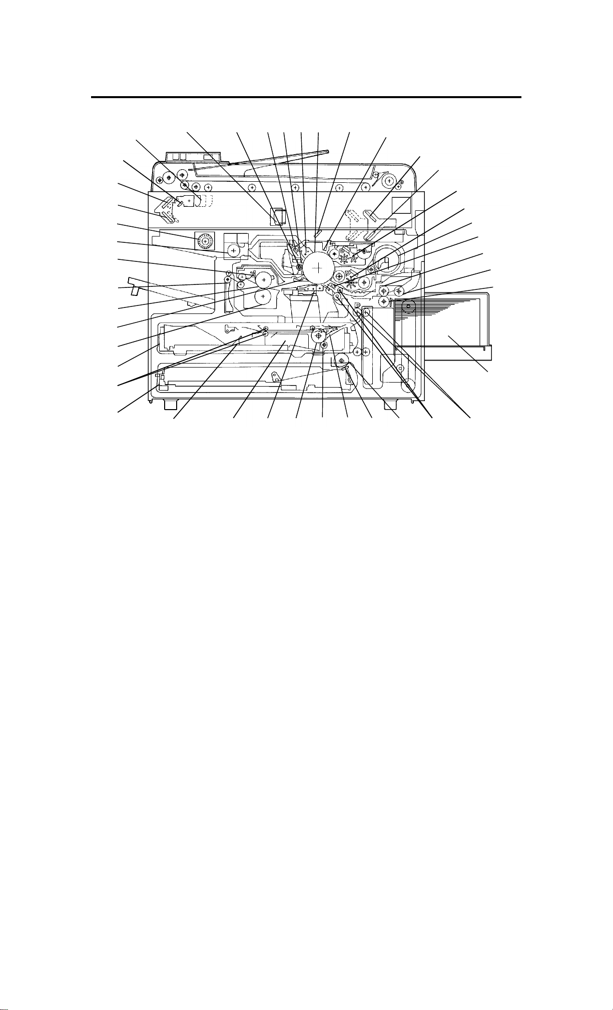
2. MECHANICAL COMPONENT LAYOUT
424142
40
39
38
37
36
35
34
111098765
4
3
2
1
12
13
14
15
16
17
18
19
20
21
22
33
32 31 30
1. 3rd Mirror
2. 2nd Mirror
3. 1st Mirror
4. Exposure Lamp
5. Lens
6. Cleaning Brush
7. Quenching Lamp
8. Cleaning Blade
9. Change Corona Unit
10. OPC Drum
11. 6th Mirror
12. Erase Unit
13. 4th Mirror
14. 5th Mirror
15. Color Development Unit
16. Black Development Unit
17. Black Toner Supply Unit
18. Pre-Transfer Lamp
19. Feed Roller
20. Pick-up Roller
21. Separation Roller
29 28 27
26 25 24 23
22. Large Capacity Tray
23. Relay Rollers
24. Registration Rollers
25. Paper Tray Feed Roller
26. Friction Pad
27. Turn Gate
28. Duplex Friction Roller
29. Duplex Feed Roller
30. Transfer & Separation
Corona Unit
31. Jogger Fences
32. End Fence
33. Lower Paper Tray
34. Entrance Rollers
35. Duplex Tray
36. Pressure Roller
37. Pick-off Pawls
38. Hot Roller
39. Junction Gate
40. Hot Roller Strippers
41. Transport Fan
42. Fusing Exhaust Fan
FSM 2-3 FT5733/5433

3. DRIVE LAYOUT
23
22
21
20
1
26
25
24
2
19
18
17
16
13
1015
12
5
10
11
6
7
8
9
14
134
FT5733/5433 2-4 FSM

1: Main Motor Pulley
3: Fusing Drive Belt 2: Drum Drive Belt
4: Drive Distribution
Gear/Pulley
23: Drive Distribution Belt Cleaning drive Gear 9: Fusing Unit
12: Drive Distribution
Gear/Pulley
25: Drum Drive Pulley 24: Development Drive
Drum Development
Cleaning Unit Fusing
20: Toner Supply Drive
Gear/Pulley
22: Toner Supply
CL Gear
21: Development Unit
Shift Gears
26: Development Drive
Belt
CL Pulley
Drive Gear
6: Copier Exit Roller
Gear
7: Duplex Transport
Drive Belt
8: Duplex Transport
Roller Pulley
19: Paper Feed
Drive
16: Paper Feed
Drive Belt
14: Lower paper
Feed CL Gear
10: Registration CL Gear
11: Upper Paper Feed
13: Feed Relay CL Gear
17: Relay Roller
18: By-pass Feed
CL Gear
15: Tray Unit drive
Gear
5: Sorter Adapter Gears
FSM 2-5 FT5733/5433

4. ELECTRICAL COMPONENT DESCRIPTION
Refer to the electrical component layout on the reverse side of the
Point to Point (Water proof paper) for symbols and index numbers.
Symbol Name Function Index
No.
Motors
M1 Main Drives the main unit components. 1
M2 Exhaust blower Blows the ozone built up around the
charge section through the ozone
filter.
M3 Upper tray lift
(non-duplex
machine only)
M4 Lower tray lift Raises the bottom plate in the lower
M5 Transport fan Provides air flow to the transport
M6 Fusing exhaust
fan
Raises the bottom plate in the upper
paper tray.
paper tray.
section so that paper is held on the
transport guide. Also the air flow
isolates the toner collection tank from
fusing heat.
Provides air flow to the charge
corona section as well.
Removes the heat from around the
fusing unit.
6
31
28
65
66
M7 Scanner drive Drives the 1st and 2nd scanners (dc
stepper).
M8 3rd scanner
drive
M9 Optics cooling
fan
M10 Lens drive Positions the lens. 100
M11 Duplex feed
(duplex
machine only)
M12 Jogger (duplex
machine only)
Drives the 3rd scanner (dc stepper). 75
Removes heat from the optics unit. 77
Drives the feed roller and moves the
bottom plate up and down (24 V dc
stepper).
Drives the jogger fences to square
the paper stack in the duplex tray (dc
stepper).
67
103
107
FT5733/5433 2-6 FSM

Symbol Name Function Index
No.
M13 LCT lift Lifts up and lowers the LCT bottom
plate.
Circuit Board
PCB1 dc power supply Drives the exposure and fusing
lamps and rectifies 100 Vac or
220/230/240 Vac input and outputs
dc voltages.
PCB2 Main control Controls all copier functions both
directly and through the other control
boards.
PCB3 Scanner motor
control
PCB4 Main motor
control
Controls the speed of the scanner
drive motor.
Controls the rotation of the main
motor.
79
44
10
69
71
PCB5 Operation panel Controls the LED matrix, and
monitors the key matrix.
PCB6 ADS sensor Senses the background density of
the original.
PCB7 High voltage
supply - CTBG
Supplies high voltage for the charge
corona, grid bias, transfer corona,
and development bias.
PCB8 High voltage
supply - D
PCB9 PTL/QL
stabilizer
PCB10 Duplex control
(duplex
Supplies high voltage for the
separation corona.
Provides high voltage for the
quenching and pre-transfer lamps.
Controls the rotation of the duplex
feed motor.
machine only)
93
90
9
8
73
106
PCB11 LCT interface
(LCT machine
only)
PCB12 Guidance
Interfaces the LCT control signal
80
between the main control board and
the LCT.
Controls the guidance display board. 92
display control
(duplex
machine only)
PCB13 Guidance
display (duplex
Displays guidance for machine
operation.
94
machine only)
FSM 2-7 FT5733/5433

Symbol Name Function Index
No.
PCB14 Interface - type
G (option for
sorter stapler
and menu
reader)
Switches
SW1 Upper paper
size - 1
(non-duplex
machine only)
SW2 Upper paper
size - 2
(non-duplex
machine only)
SW3 Upper paper
size - 3
(non-duplex
machine only)
Interfaces the sorter stapler and
menu reader with the main control
board.
Determines what size paper is in the
upper paper tray.
Determines what size paper is in the
upper paper tray.
Determines what size paper is in the
upper paper tray.
16
2
3
4
SW4 Upper paper
size - 4
Determines what size paper is in the
upper paper tray.
(non-duplex
machine only)
SW5 Lower paper
size - 1
SW6 Lower paper
size - 2
SW7 Lower paper
size - 3
SW8 Lower paper
size - 4
Determines what size paper is in the
lower paper tray.
Determines what size paper is in the
lower paper tray.
Determines what size paper is in the
lower paper tray.
Determines what size paper is in the
lower paper tray.
SW9 Color detection Detects if color development unit is
set or not and which color toner
development unit is installed.
5
36
34
33
32
13
SW10 Exit cover
Cuts the ac power line. 64
(Duplex
machine only)
SW11 Platen cover Informs the CPU when the platen
88
cover is closed.
FT5733/5433 2-8 FSM

Symbol Name Function Index
No.
SW12 Front door safety Cuts the ac power line through RA1
91
and detects if the front door is open
or not.
SW13 Main Supplies power to the copier. 95
SW14 LCT cover - 1 Detects if the LCT cover is open or
83
not.
SW15 LCT cover - 2 Cuts the dc power line of the LCT lift
84
motor.
SW16 LCT down Sends a signal to the CPU to lower
85
the LCT bottom plate.
Lamps
L1 Quenching Neutralizes any charge remaining on
47
the drum surface after cleaning.
L2 Pre-transfer Reduces the charge on the drum
49
surface before transfer.
L3 Fusing Provides heat to the hot roller. 60
L4 Exposure Applies high intensity light to the
99
original exposure.
L5 Erase Eliminates the charge for
48
unnecessary areas of the image on
the drum surface before exposure.
Magnetic
Clutches
MC1 Development
Drives the development roller. 11
drive
MC2 Toner supply Drives the toner supply roller. 14
MC3 By-pass feed Starts paper feed from the by-pass
17
feed table or LCT.
MC4 Feed relay Drives the relay rollers. 19
MC5 Registration Drives the registration rollers. 20 No.
MC6 Upper paper
feed
Starts paper feed from the upper
paper tray.
22
(non-duplex
machine only)
FSM 2-9 FT5733/5433

Symbol Name Function Index
No.
MC7 Lower paper
feed
Starts paper feed from the lower
paper tray.
Solenoids
SOL1 Development
unit change
Changes the position of the black
development unit and color
development unit.
SOL2 Pick-up roller Picks paper up from the by-pass
feed table or LCT.
SOL3 Duplex tray lock
(duplex
Locks the duplex tray in the main
copier.
machine only)
SOL4 Upper tray lock
(non-duplex
Locks the upper paper tray in the
main copier.
machine only)
24
12
18
29
39
SOL5 Lower tray lock Locks the lower paper tray in the
main copier.
SOL6 Junction gate
(duplex
machine only)
SOL7 Duplex turn
gate (duplex
machine only)
Moves the junction gate to direct
copies to the duplex tray or to the
paper exit.
Moves the duplex turn gate to direct
copies to the duplex tray or to the
relay rollers.
Sensors
S1 By-pass feed
table
S2 Upper tray set
(non-duplex
Detects if the by-pass feed table is
open or closed.
Detects if the upper paper tray is set
or not.
machine only)
37
43
105
15
21
S3 Lower tray set Detects if the lower paper tray is set
26
or not.
S4 By-pass feed
paper end
S5 Upper tray
paper end
Informs the CPU that there is no
paper in the by-pass feed table.
Informs the CPU when the upper
paper tray runs out of paper.
53
23
(non-duplex
machine only)
FT5733/5433 2-10 FSM

Symbol Name Function Index
No.
S6 Lower tray
paper end
S7 Upper tray
upper limit
(non-duplex
Informs the CPU when the lower
paper tray runs out of paper.
Detects the upper position of the
paper stack in the upper tray to stop
the upper lift motor.
machine only)
S8 Lower tray
upper limit
Detects the upper position of the
paper stack in the lower tray to stop
the lower lift motor.
S9 Lower relay Detects the lead edge of paper from
the lower paper tray to determine the
stop timing of the lower paper feed
clutch and detects misfeeds.
S10 Upper relay Detects the lead edge of paper from
the upper paper tray to determine the
stop timing of the upper paper feed
clutch and detects misfeeds.
25
30
27
51
50
S11 Registration Detects the lead edge of paper to
52
determine the stop timing of the feed
relay clutch and detects misfeeds.
S12 Image density
(ID)
Detects the density of the ID sensor
pattern on the drum to control the
57
toner density.
S13 V Detects the VR and VL patterns. 58
S14 Fusing exit Detects misfeeds. 62
S15 Junction gate
Detects misfeeds. 63
(duplex
machine only)
S16 Scanner H.P. Informs the CPU when the 1st
68
scanner is at the home position.
S17 Lens H.P. Informs the CPU when the lens is at
72
the full-size position.
S18 Platen position Informs the CPU when the platen
74
cover is positioned. When the angle
between, the platen cover and the
exposure glass is about 30 degrees.
S19 3rd scanner H.P. Informs the CPU when the 3rd
76
scanner is in the full size position.
FSM 2-11 FT5733/5433

Symbol Name Function Index
No.
S20 Original length Detects the original length. 89
S21 Original width Detects the original width. 96
S22 Duplex entrance
(duplex
machine only)
S23 Duplex turn
gate (duplex
machine only)
S24 Duplex paper
end (duplex
machine only)
S25 Jogger H.P.
(duplex
machine only)
S26 LCT paper end
(LCT machine
only)
Detects misfeed. 109
Detects the trail edge of paper to
101
determine the reverse timing of the
duplex motor and detects misfeed.
Detects copy in the duplex tray. 102
Detects if the jogger fences are at
108
home position.
Informs the CPU when the LCT runs
82
out of paper.
S27 LCT lower limit
(LCT machine
Sends signal to CPU to stop lowering
the LCT bottom plate.
only)
S28 LCT upper limit
(LCT machine
Sends signal to CPU to stop lifting up
the LCT bottom plate.
only)
Heaters
H1 Drum Turns on when the main switch is off
to prevent moisture around the drum.
H2 Optics
anti-condensation
(option)
H3 Upper tray
(option)
Turns on when the main switch is off
to prevent moisture from forming on
the optics.
Turns on when the main switch is off
to keep paper dry in the upper paper
tray.
81
78
54
97
55
H4 Lower tray
(option)
Turns on when the main switch is off
to keep paper dry in the lower paper
87
tray.
FT5733/5433 2-12 FSM

Symbol Name Function Index
No.
Thermistor
TH1 Drum Monitors the temperature around the
drum.
TH2 Fusing Monitors the temperature of the hot
roller.
TH3 Optics Monitors the temperature of the
optics cavity.
TH4 Duplex motor
(duplex
Monitors the temperature of the
duplex motor.
machine only)
Thermofuse
TF1 Fusing Provides back-up overheat
protection in the fusing unit.
56
59
98
104
61
Thermoswitch
TS1 Optics Provides overheat protection in the
70
optics unit.
Noise filter
NF1 Removes electrical noise. 40
Fuse
FU1 Main (115 V
machine only)
Provides back-up high current
protection in the electrical
42
components.
FU2 Sorter line (115
V machine only)
Provides back-up high current
protection in the electrical
46
components of the sorter.
FU3 DF line (115 V
machine only)
Provides back-up high correct
protection in the electrical
7
components of the ARDF.
Circuit Breaker
CB1 (230 V machine
only)
Provides back-up high current
protection in the electrical
41
components.
FSM 2-13 FT5733/5433

Symbol Name Function Index
No.
Relay
RA1 Main power Controls main power. 45
Transformer
TR1 Main Steps down the wall voltage to 100 V
ac.
Counter
CO1 Total Keeps track of the total number of
copies made.
38
86
FT5733/5433 2-14 FSM

SECTION 3
INSTALLATION

1. INSTALLATION REQUIREMENT
1.1 ENVIRONMENT
1. Temperature Range: 10oC to 30oC (50oF to 86oF)
2. Humidity Range: 15% to 90% RH
3. Ambient Illumination: Less than 1,500 lux (do not expose to direct
sunlight)
4. Ventilation: Minimum space 20 m3. Room air should turn over at
least 30 m3/hr/person.
5. Ambient Dust: Less than 0.15 mg/m3 (4 x 10⁻⁶ oz/yd3)
6. If the machine location is air-conditioned or heated, place the
machine:
a) where it will not be subjected to sudden
temperature changes.
b) where it will not be directly exposed to cool
air from an air-conditioner in the summer.
c) where it will not be directly exposed to
reflected heat from a space heater in winter.
7. Avoid placing the machine in an area filled with corrosive gas.
8. Avoid any places higher than 2,000 meters (6,500 feet) above
sea level.
9. Place the machine on a strong and level base.
10. Avoid any area where the machine may be frequently subjected
to strong vibration.
FSM 3-1 FT5733/5433

1.2 MACHINE LEVEL
1. Front to back level: within 5 mm (0.2")
2. Right to left level: within 5 mm (0.2")
Use a carpenter’s level to level the machine
1.3 MINIMUM SPACE REQUIREMENTS
Copier only
a
d
a: more than 10 cm/3.9"
(When the micro sorter is
installed: 15 cm/5.9")
b: more than 40 cm/15.7"
c: more than 80 cm/31.5"
d: (When you use the copy
tray): more than 30
cm/11.8"
c
b
Full system
e
h
f
g
e: more than 10 cm/3.9" (When the
micro sorter is installed: 15
cm/5.9")
f: more than 40 cm/15.7"
g: more than 80 cm/31.5"
h: more than 20 cm/11.8" (When
the sorter stapler is installed: 10
cm/3.9")
NOTE: When the micro sorter is equipped, make sure there is at
least 15 cm (6.0") clearance on the back side, in order to
avoid damaging the sorter when it is opened.
FT5733/5433 3-2 FSM

1.4 POWER REQUIREMENTS
1. Input voltage level:
110V/60Hz : More than 15A (for Taiwan)
115V/60Hz : More than 15A (for N.A.)
220V/230V/240V/50Hz : More than 8A (for EU.)
220V/60Hz : More than 8A
2. Permissible voltage fluctuation: ±10%
3. Do not set anything on the power cord.
NOTE: a) Make sure the plug is firmly inserted in the outlet.
b) Avoid multi-wiring.
FSM 3-3 FT5733/5433

2. COPIER INSTALLATION
2.1 COPIER INSTALLATION
2.1.1 Accessory Check
1. Receiving Tray.................................................................1
2. Outer Decal - Symbol Explanation..................................1
3. Sorter Key Top and Cover...............................................1
4. Counter Set Key (--17 machine only) ..............................1
5. Installation Procedure......................................................1
6. Operating Instructions (Except --27 machine).................1
7. Now Equipment Condition Report
(--17, --19, --27, --29 machine only)..................................1
8. Envelope for NECR (--17 machine only) ......................... 1
9. User Survey Card (--17 machine only)............................1
FT5733/5433 3-4 FSM

2.1.2 Installation Procedure
[A]
[A]
[B]
[G]
[F]
[C]
[H]
[D]
[E]
[A]
NOTE: Keep the shipping retainers after installing the machine.
They will be reused if in the future the machine is
transported to another location.
Proper reinstallation of the shipping retainers is required in
order to avoid any transport damage. It is important to
replace the scanner lock pins and the scanner lock plate
before transporting this copier. If it is not done, skewed
image may result.
1. Remove the 7 strips of tape [A] as shown.
2. Open the front door and remove 4 strips of tape [B] as shown.
3. Pull out the paper tray [C], and remove a strip of tape [D] and the
foam block [E] (1 tray for the duplex machine and 2 trays for the
non-duplex machine).
4. Pull out the duplex tray [F] and remove the 2 strips of tape [G]
and 3 sheets of paper [H] (duplex machine only).
FSM 3-5 FT5733/5433

[B]
[A]
[D]
[C]
[E]
5. Remove the left scale [A] (2 shoulder screws).
6. Remove the scanner lock pin [B] simply by pulling it up from the
front and the rear side of the left scale bracket.
7. Reinstall the left scale.
8. Remove the left optics cover [C] (1 screw).
9. Remove the scanner lock plate [D] (1 screw) by pulling and lifting
it up and reinstall the left optics cover.
10. Remove the shipping retainer [E] holding the ozone filter. The
retainer is taped on the upper exit cover.
FT5733/5433 3-6 FSM

[C]
[B]
[A]
[C]
[D]
[E]
[F]
11. Push the development unit lock lever [A] to the right (to the lock
position).
12. Move the development release lever [B] to the right and pull out
the black development unit [C] half way. Holding the toner supply
unit [D] with your right hand and the bottom of the development
unit with your left hand, pull the unit all the way out . Place the unit
on a clean sheet of paper.
13. Separate the toner supply unit from the development unit (3
screws).
14. Pour one pack of black developer [E] into the development unit
while turning the development roller knob [F] counterclockwise.
This will distribute the developer inside the unit.
15. Remount the toner supply unit on the development unit.
FSM 3-7 FT5733/5433

[B]
Rev. 10/92
[C]
[A]
[E]
16. Lower the transfer & separation corona unit by pulling down the
release lever [A].
17. Turn the cleaning unit release lever [B] counterclockwise to the
upright position. (The cleaning unit is released from the drum.)
18. Remove the drum protective sheet [C] from the development unit
opening.
CAUTION: To avoid damaging the pick-off pawls, remove the
drum protective sheet by pulling the lower side as
shown in the figure.
[D]
19. Turn the cleaning unit release lever clockwise to the set position.
20. Remove the cleaning blade lock plate [D].
21. Reset the transfer & separation corona unit [E].
FT5733/5433 3-8 FSM

[C]
[E]
[B]
[A]
[C]
[D]
[F]
22. Install the black development unit [A] in the copier, and remove
the cover sheet [B] from the toner supply unit.
NOTE: • When installing the development unit, be sure that the
development unit rail is placed directly on the
development unit guide rail.
• Make sure that the development release lever [C] is in
its original position after the development unit is set.
23. Shake the toner cartridge [D] well from side to side. While
pushing the toner cartridge in, insert it halfway into the holder with
the seal [E] up.
24. As you peel off the seal, insert the cartridge completely. While
pushing the toner cartridge in, turn it counterclockwise until it
stops.
25. Slide out the charge corona unit [F] until it is fully extended and
push it back in to the original position. Repeat this action several
times.
FSM 3-9 FT5733/5433
 Loading...