

Ricoh 5733 Diagram

FT5733/5433
(contains FT4727/4427 Information)
SERVICE TRAINING
MANUAL

SECTION 1
OVERALL MACHINE
INFORMATION
1. SPECIFICATIONS
Configuration: Desktop
Copy Process: Dry electrostatic transfer system
Originals: Sheet/Book
Original Size: Maximum 11" x 17"
Copy Paper Size: Maximum 11" x 17"
Minimum 51/2" x 81/2" By-Pass Tray Only
(Duplex Copying)
Multiple:
Single/Overlay:
81/2" x 11" (sideways)
Maximum 11" x 17"
Minimum 81/2" x 11"
Rev. 10/92
Copy Paper Weight: • 250-sheet paper tray and 1000-sheet large
capacity tray:
14 _34lb
• By-pass feed table:
14 _43lb
• Duplex and overlay:
17 _28lb
Reproduction Ratios: 4 Enlargement and 6 Reduction
FT5733/5433
200%
Enlargement
Full Size 100%
Reduction
155%
129%
121%
93%
85%
77%
74%
65%
50%
Receiving Tray
Capacity:
250 sheets (81/2" x 14" and smaller)
100 sheets (11" x 17")
Power Source: 115V, 60HZ, more than 12A
STM 1-1 FT5733/5433

Rev. 10/92
Power Consumption: Maximum: 1.5 KW
Warm-up: 0.77 KW
Stand-by: 0.14 KW
Copy Cycle (average): 1.2 KW
Noise Emission: Stand-by: less than 40 dB
Copy Cycle (average):
less than 57 dB (copier only)
less than 59 dB (full system)
Maximum:
less than 62 dB (copier only)
less than 63 dB (full system)
Dimensions:
Width Depth Height
FT5733 34.3" (42.2") 23.6" 21.3" (22.6")
FT5433 34.3" (42.2") 23.6" 21.3" (22.6")
( ): When the by-pass feed table is opened, the copy tray is
extended, and the platen cover is installed.
Weight: Copier only (Without the optional platen cover
= Approximately 2 kg)
FT5733: approximately 194.0 lb
FT5433: approximately 185.2 lb
Zoom: From 50% to 200% in 1% steps
Copying Speed: 33 copies/minute (81/2" x 11" sideways)
18 copies/minute (11" x 17")
Warm-up Time: Less than 2 minutes (20°C, 68°F)
First Copy Time: Black copy:
4.9 seconds (81/2" x 11" sideways)
FT5733/5433: (Large capacity tray feed)
Color copy:
7.0 seconds
FT5733/5433: (Large capacity tray feed)
FT5733/5433 1-2 STM

Rev. 11/92
Copy Number Input: Ten keys, 1 to 999 (count up or count down)
Manual Image Density: 7 steps
Automatic Reset: 1 minute standard setting; can also be set to
3 minutes or no auto reset.
Copy Paper Capacity: • By-pass feed table; approximately 20 sheets
• Paper tray: approximately 250 sheets
• Large capacity tray; approximately 1000 sheets
Toner Replenishment: Black: cartridge exchange
(320 g/cartridge) yield 10,500 copies
Color: cartridge exchange
(60 g/cartridge) yield 1300 copies
Developer
Black: (1000 g/bag) yield 80,000 copies
Replenishment:
Color: (400 g/bag) yield 15,000 copies
Optional Equipment: • Platen cover
• DF56, Document feeder
• PS250, Paper tray unit with three paper tray
• CS2090, 20 bin mini sorter
• ST22, 20 bin sorter stapler
• TYPE G Sorter adapter (needed when installing
the mini, or the sorter stapler)
• TYPE G Interface PCB (needed when installing
the sorter stapler or the menu reader)
• MR20, Menu reader
• RE12, Editor (only for FT5733)
• TYPE B, Editing interface adapter (needed when
installing the editor)
• CU150, Color development unit
• Key counter
• DLT counter (service part)
STM 1-3 FT5733/5433
2. MACHINE CONFIGURATION
2.1 COPIER
FT5733(A074) FT5433(A073)
UPPER TRAY DUPLEX 250
LOWER TRAY 250 250
LCT 1,000 1,000
Rev. 1/94
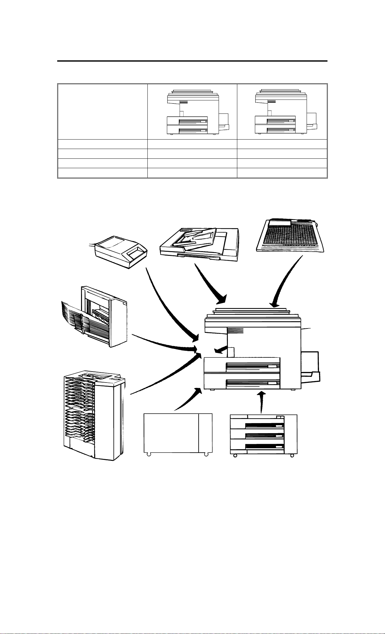
2.2 OPTIONAL EQUIPMENT
DF56
MR20
MENU READER (A952)
CS2090
20 BIN SORTER
(A423)
ARDF (A497)
RE12
EDITOR
ST22
SORTER STAPLER
(A366)
FT5733/5433
COPIER CABINET
(438-MIU)
PS250
PAPER TRAY UNIT
(A326)
FT5733/5433 1-4 STM

2.3 CONFIGURATION TABLE
COPIER REQUIRED OPTIONAL EQUIPMENT
FT5733
TYPE 2
(A074)
3 TRAY
PAPER
TRAY UNIT
DOCUMENT
FEEDER
EDITOR (A916) o x * * *
MENU READER (A952) o o * *
COLOR DEVELOPMENT
UNIT (A337)
(A326)
20 BIN MINI
(A423)
20 BIN
STAPLER
(A366)
ARDF
(A497)
FT5433
TYPE 3
(A073)
o o
o o *
o o * * *
o o
o o
SORTER
ADAPTER
(A328)
INTERFACE
PCB
(A344)
Rev. 6/93
EDITING INTERFACE
ADAPTER (A345)
NOTE1: * The sorter adapter is required to install the 20 bin
mini sorter or sorter stapler.
* * The I/F board is required to install the sorter stapler
or Menu Reader.
* * * (1) The editing interface adapter is required to
install the editor.
(2) The editing interface adapter can be installed
independently when more precise erasing is
desired.
NOTE 2: When installing the sorter stapler, the copier must be
placed on the paper tray unit or the system table or
copier cabinet.
STM 1-5 FT5733/5433

3. COPY PROCESS AROUND THE DRUM
2. EXPOSURE
4. DEVELOPMENT
9. QUENCHING
8. CLEANING
1. DRUM
CHARGE
3. ERASE
(COLOR)
4. DEVELOPMENT
(BLACK)
ID/V SENSORS
PICK-OFF
PAWLS
7. PAPER
5. PRE-TRANSFER
LAMP
6. IMAGE TRANSFER
SEPARATION
FT5733/5433 1-6 STM

1. DRUM CHARGE
In the dark, the charge corona unit gives a uniform negative charge
to the organic photo conductive (OPC) drum. The charge remains on
the surface of the drum because the OPC layer has a high electrical
resistance in the dark. The amount of negative charge on the drum is
proportional to the negative grid bias voltage applied to the grid plate
on the charge corona unit.
2. EXPOSURE
An image of the original is reflected to the OPC drum surface via the
optics assembly. The charge on the drum surface is dissipated in
direct proportion to the intensity of the reflected light, thus producing
an electrical latent image on the drum surface.
The amount of remaining charge as a latent image on the drum
depends on exposure lamp intensity controlled by the exposure lamp
voltage.
3. ERASE
The erase lamp illuminates the areas of the charged drum surface
that will not be used for the copy image. The resistance of the drum
in the illuminated areas drops and the charge on those areas
dissipates.
4. DEVELOPMENT
Positively charged toner is attracted to the negatively charged areas
of the drum, thus developing the latent image. (The positive
triboelectric charge is caused by friction between the carrier and
toner particles.)
The development bias voltage applied to the development roller shaft
controls two things:
1) The threshold level if toner is attracted to the drum or toner
remains on the development roller.
2) The amount of toner to be attracted to the drum.
The higher the negative development bias voltage is, the less toner
is attracted to the drum surface.
5. PRE-TRANSFER LAMP (PTL)
The PTL illuminates the drum to remove almost all the negative
charge from the exposed areas of the drum. This prevents the toner
particles from being reattracted to the drum surface during paper
separation and makes paper separation easier.
STM 1-7 FT5733/5433

Rev. 10/92
6. IMAGE TRANSFER
Paper is fed to the drum surface at the proper time so as to align the
copy paper and the developed image on the drum surface. Then, a
strong negative charge is applied to the reverse side of the copy
paper, producing an electrical force which pulls the toner particles
from the drum surface onto the copy paper. At the same time, the
copy paper is electrically attracted to the drum surface.
7. PAPER SEPARATION
A strong ac corona discharge is applied to the reverse side of the
copy paper, reducing the negative charge on the copy paper and
breaking the electrical attraction between the paper and the drum.
Along with the ac charge is a dc bias which will hold the toner in
place and prevent toner scatter. Then, the stiffness and the weight of
the copy paper causes it to separate from the drum surface. The
pick-off pawls help to separate paper and drum.
8. CLEANING
The cleaning brush removes toner remaining on the drum after
image transfer and the cleaning blade scrapes off all the remaining
toner.
9. QUENCHING
Light from the quenching lamp electrically neutralizes the charge
potential of the drum surface.
FT5733/5433 1-8 STM
Rev. 1/94
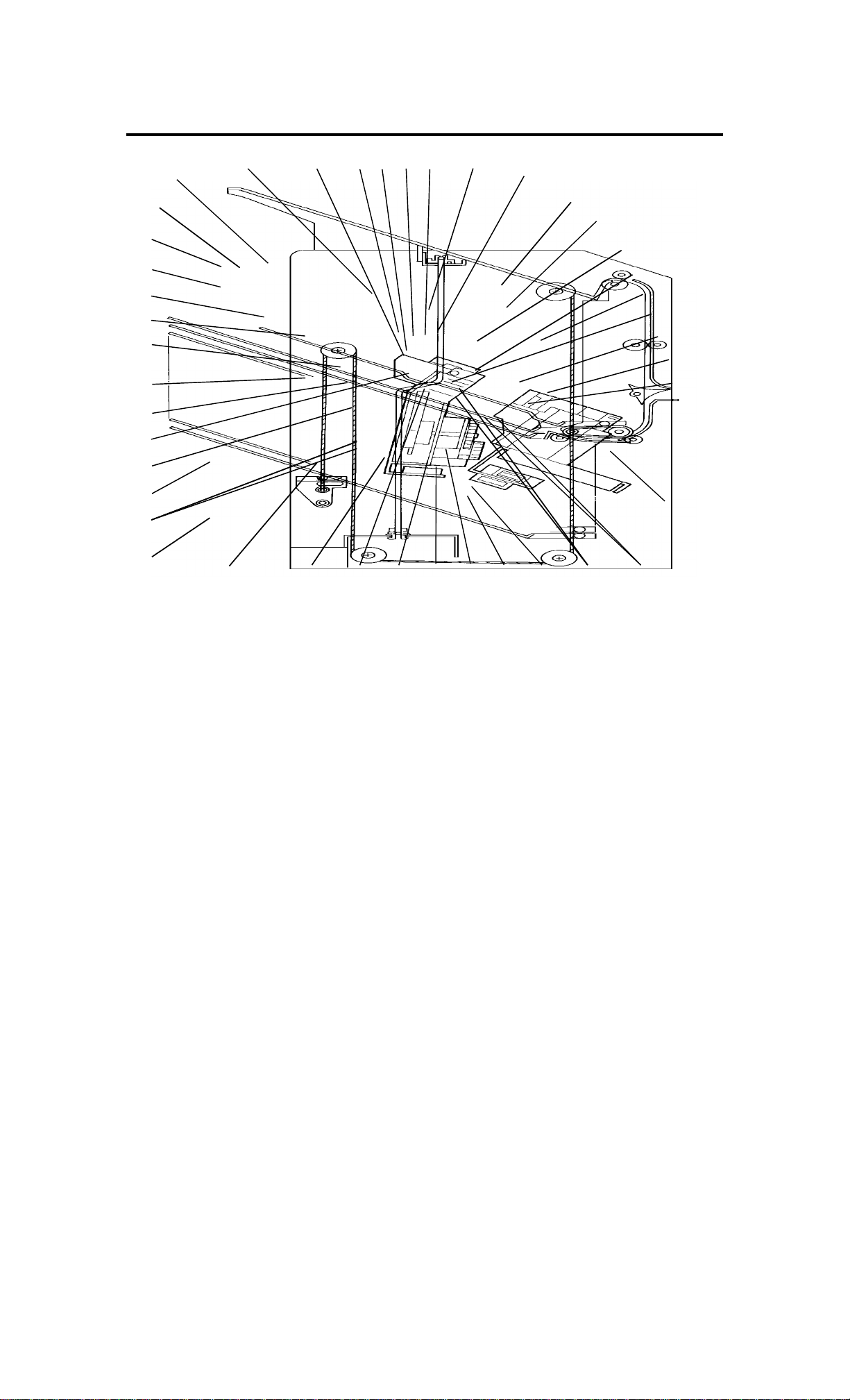
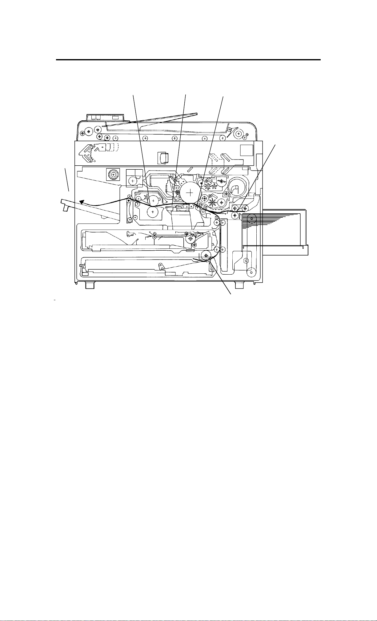
4. MECHANICAL COMPONENT LAYOUT
424142
40
39
38
37
36
35
34
33
111098765
4
3
2
1
32 31
30
29 28 27
12
13
14
15
16
17
18
19
20
21
22
26 25 24 23
1. 3rd Mirror
2. 2nd Mirror
3. 1st Mirror
4. Exposure Lamp
5. Lens
6. Cleaning Brush
7. Quenching Lamp
8. Cleaning Blade
9. Change Corona Unit
10. OPC Drum
11. 6th Mirror
12. Erase Unit
13. 4th Mirror
14. 5th Mirror
15. Color Development Unit
16. Black Development Unit
17. Black Toner Supply Unit
18. Pre-Transfer Lamp
19. Feed Roller
22. Large Capacity Tray
23. Relay Rollers
24. Registration Rollers
25. Paper Tray Feed Roller
26. Friction Pad
27. Turn Gate
28. Duplex Friction Roller
29. Duplex Feed Roller
30. Transfer & Separation
Corona Unit
31. Jogger Fences
32. End Fence
33. Lower Paper Tray
34. Entrance Rollers
35. Duplex Tray
36. Pressure Roller
37. Pick-off Pawls
38. Hot Roller
39. Junction Gate
20. Pick-up Roller
21. Separation Roller
40. Hot Roller Strippers
41. Transport Fan
42. Fusing Exhaust Fan
STM 1-9 FT5733/5433
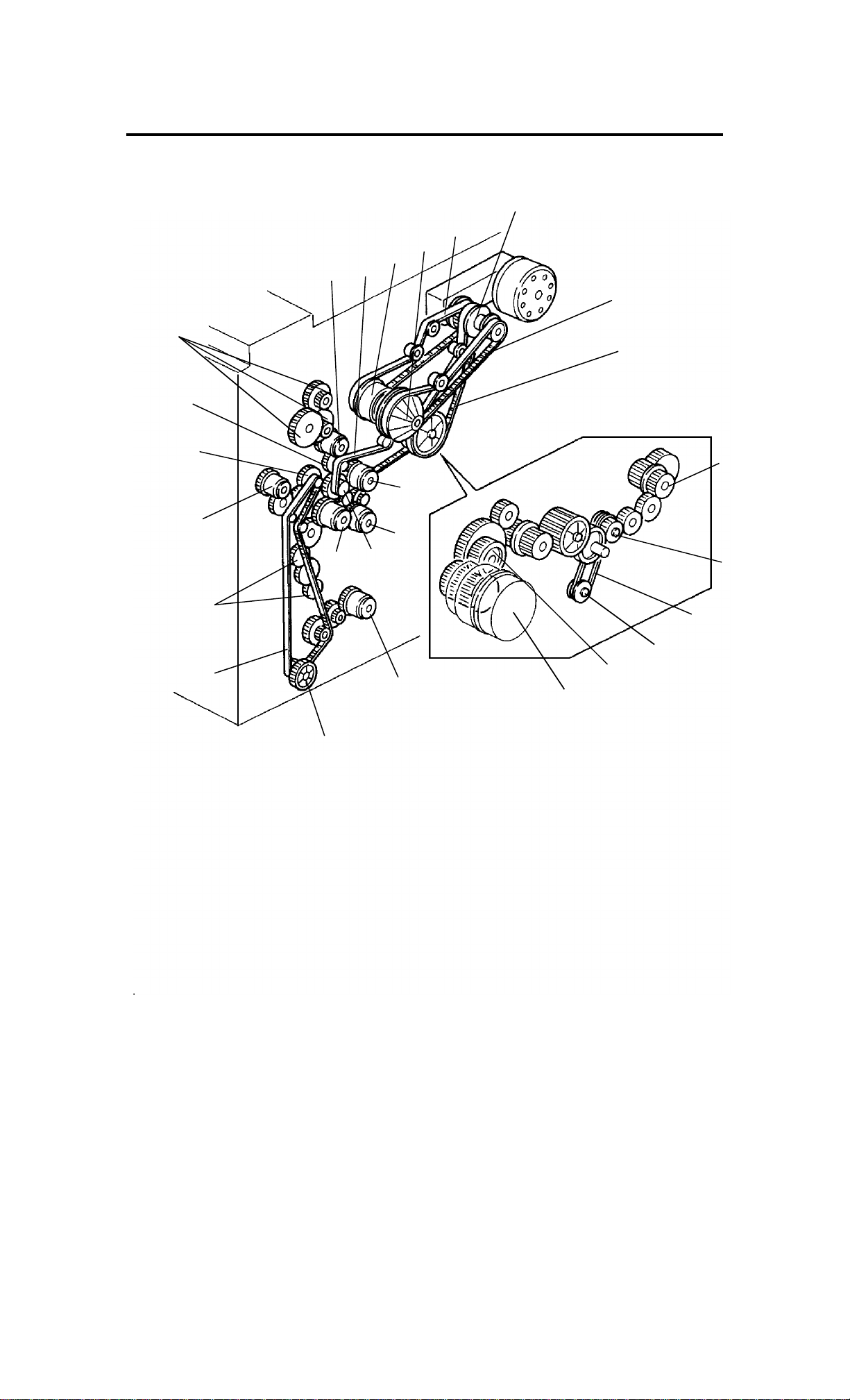
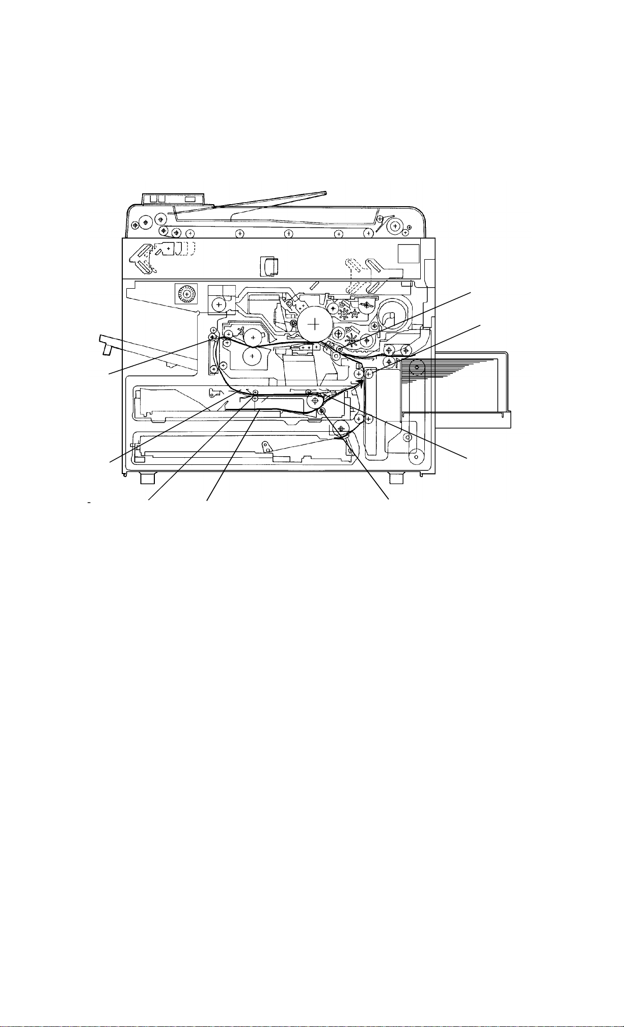
5. DRIVE LAYOUT
23
22
21
20
1
26
25
24
2
19
18
17
16
13
1015
12
5
10
11
6
7
8
9
14
134
FT5733/5433 1-10 STM

1: Main Motor Pulley
3: Fusing Drive Belt
4: Drive Distribution
Gear/Pulley
23: Drive Distribution
Belt
12: Drive Distribution
Gear/Pulley
2: Drum Drive
25: Drum Drive
Drum
Cleaning drive
Cleaning Unit
20: Toner Supply Drive
Gear/Pulley
22: Toner Supply
CL Gear
21: Development
Unit Shift
10: Registration CL
26: Development
Drive Belt
24: Development
Drive CL Pulley
Development
9: Fusing Unit
Drive Gear
Fusing
6: Copier Exit
Roller Gear
7: Duplex Transport
Drive Belt
8: Duplex Transport
Roller Pulley
11: Upper Paper
13: Feed Relay CL
17: Relay Roller
19: Paper Feed Drive
Gear/Pulley
18: By-pass Feed
16: Paper Feed
Drive Belt
14: Lower paper
Feed CL Gear
5: Sorter Adapter Gears
CL Gear
15: Tray Unit drive
Gear
STM 1-11 FT5733/5433
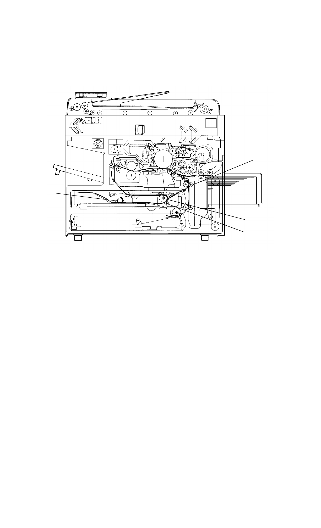
6. PAPER PATH
6.1 NORMAL COPYING
[E]
[D]
[C]
[B]
[A]
[A]
Paper feed begins from the LCT or paper tray unit paper feed
stations. The copy paper then follows one of two paths inside the
copier. The path followed depends on which mode the operator has
selected. For copy processing, all sheets follow the same path from
the paper feed mechanism [A] through the registration [B], T & S
corona [C], and fusing unit [D]. After that, normal copies are
delivered to the copy tray [E], however, 2 sided copies and overlay
copies are diverted for further processing.
FT5733/5433 1-12 STM
6.2 MULTIPLE 2-SIDED COPYING
[A]
[H]
[G]
[B]
[C]
[F]
[E]
[D]
Only paper that is 81/2" X 11" sideways can be used for multiple
2-sided copying. In this mode the junction gate [A] directs sheets
exiting the fusing unit to the duplex tray entrance [B]. After that, all
sheets follow the path through the entrance rollers [C], and the turn
gate [D]. The turn gate directs paper through the duplex feed
mechanism [E] to the duplex tray [F]. After all sheets are stacked in
the duplex tray, they exit the duplex unit via the duplex feed
mechanism and relay rollers [G] to the registration rollers [H]. After
that, the sheets follow the same path as normal copying from the
registration rollers to the copy tray.
STM 1-13 FT5733/5433
6.3 SINGLE 2-SIDED COPYING
[A]
[D]
[B]
[C]
All US (letter) sizes, excluding half letter, can be used for single 2
sided copying. In this mode, the sheet follows the same path as in
multiple 2-sided copying to the duplex tray. However, the end fence
[A] of the duplex tray lowers. The sheet advances over the lowered
end fence. The sheet is stopped by the friction between the duplex
feed and friction rollers [B,C]. It is then directed to the relay rollers [D]
by the reversed duplex feed roller. After that, the sheet follows the
same path as in multiple 2-sided copying from the relay rollers to
copy the tray.
FT5733/5433 1-14 STM

6.4 SINGLE IMAGE OVERLAY COPYING
[B]
[A]
In this mode, the sheet follows the same path as in multiple 2-sided
copying to the turn gate [A]. The turn gate directs the sheet to the
relay rollers [B]. The sheet stays there to allow the second original to
be placed and to exchange the black and color development units if
the color overlay mode has been selected by the operator. After that,
the sheet follows the same path as in multiple 2-sided copying from
the relay rollers to the copy tray.
STM 1-15 FT5733/5433

7. ELECTRICAL COMPONENT DESCRIPTION
Refer to the electrical component layout on the reverse side of the
Point to Point (Water proof paper) for symbols and index numbers.
Symbol Name Function Index No.
Motors
M1 Main Drives the main unit
components.
M2 Exhaust
blower
M3 Upper tray lift
(non-duplex
machine only)
M4 Lower tray lift Raises the bottom plate in the
M5 Transport fan Provides air flow to the
Blows the ozone built up
around the charge section
through the ozone filter.
Raises the bottom plate in the
upper paper tray.
lower paper tray.
transport section so that paper
is held on the transport guide.
Also the air flow isolates the
toner collection tank from fusing
heat.
Provides air flow to the charge
corona section as well.
1
6
31
28
65
M6 Fusing
exhaust fan
M7 Scanner drive Drives the 1st and 2nd
M8 3rd scanner
drive
M9 Optics cooling
fan
M10 Lens drive Positions the lens. 100
M11 Duplex feed
(duplex
machine only)
M12 Jogger
(duplex
machine only)
M13 LCT lift Lifts up and lowers the LCT
Removes the heat from around
the fusing unit.
scanners (dc stepper).
Drives the 3rd scanner (dc
stepper).
Removes heat from the optics
unit.
Drives the feed roller and
moves the bottom plate up and
down (24 V dc stepper).
Drives the jogger fences to
square the paper stack in the
duplex tray (dc stepper).
bottom plate.
66
67
75
77
103
107
79
FT5733/5433 1-16 STM

Symbol Name Function Index No.
Circuit Board
PCB1 DC power
supply
Drives the exposure and fusing
lamps and rectifies 100 Vac or
220/230/240 Vac input and
outputs dc voltages.
PCB2 Main control Controls all copier functions
both directly and through the
other control boards.
PCB3 Scanner motor
control
PCB4 Main motor
control
PCB5 Operation
panel
Controls the speed of the
scanner drive motor.
Controls the rotation of the
main motor.
Controls the LED matrix, and
monitors the key matrix.
PCB6 ADS sensor Senses the background density
of the original.
PCB7 High voltage
supply - CTBG
Supplies high voltage for the
charge corona, grid bias,
transfer corona, and
development bias.
44
10
69
71
93
90
9
PCB8 High voltage
supply - D
PCB9 PTL/QL
stabilizer
Supplies high voltage for the
separation corona.
Provides high voltage for the
quenching and pre-transfer
lamps.
PCB10 Duplex control
(duplex
Controls the rotation of the
duplex feed motor.
machine only)
PCB11 LCT interface Interfaces the LCT control
signal between the main control
board and the LCT.
PCB12 Guidance
display control
Controls the guidance display
board.
(duplex
machine only)
PCB13 Guidance
display
Displays guidance for machine
operation.
(duplex
machine only)
8
73
106
80
92
94
PCB14 Interface -
type G (option
for sorter
Interfaces the sorter stapler and
menu reader with the main
control board.
16
stapler and
menu reader)
STM 1-17 FT5733/5433

Symbol Name Function Index No.
Switches
SW1 Upper paper
size - 1
(non-duplex
machine only)
SW2 Upper paper
size - 2
(non-duplex
machine only)
SW3 Upper paper
size - 3
(non-duplex
machine only)
SW4 Upper paper
size - 4
(non-duplex
machine only)
SW5 Lower paper
size - 1
Determines what size paper is
in the upper paper tray.
Determines what size paper is
in the upper paper tray.
Determines what size paper is
in the upper paper tray.
Determines what size paper is
in the upper paper tray.
Determines what size paper is
in the lower paper tray.
2
3
4
5
36
SW6 Lower paper
size - 2
SW7 Lower paper
size - 3
SW8 Lower paper
size - 4
Determines what size paper is
in the lower paper tray.
Determines what size paper is
in the lower paper tray.
Determines what size paper is
in the lower paper tray.
SW9 Color detection Detects if color development
unit is set or not and which
color toner development unit is
installed.
SW10 Exit cover
Cuts the ac power line. 64
(Duplex
machine only)
SW11 Platen cover Informs the CPU when the
platen cover is closed.
SW12 Front door
safety
Cuts the ac power line through
RA1 and detects if the front
door is open or not.
34
33
32
13
88
91
SW13 Main Supplies power to the copier. 95
SW14 LCT cover - 1 Detects if the LCT cover is
83
open or not.
SW15 LCT cover - 2 Cuts the dc power line of the
84
LCT lift motor.
FT5733/5433 1-18 STM

Symbol Name Function Index No.
W16 LCT down Sends a signal to the CPU to
85
lower the LCT bottom plate.
Lamps
L1 Quenching Neutralizes any negative
47
charge remaining on the drum
surface after cleaning.
L2 Pre-transfer Reduces the charge on the
49
drum surface before transfer.
L3 Fusing Provides heat to the hot roller. 60
L4 Exposure Applies high intensity light to
99
the original exposure.
L5 Erase Eliminates the charge for
48
unnecessary areas of the
image on the drum surface
before exposure.
Magnetic
Clutches
MC1 Development
Drives the development roller. 11
drive
MC2 Toner supply Drives the toner supply roller. 14
MC3 By-pass / LCT
feed
Starts paper feed from the
by-pass feed table or LCT.
17
MC4 Feed relay Drives the relay rollers. 19
MC5 Registration Drives the registration rollers. 20
MC6 Upper paper
feed
Starts paper feed from the
upper paper tray.
22
(non-duplex
machine only)
MC7 Lower paper
feed
Starts paper feed from the
lower paper tray.
24
STM 1-19 FT5733/5433

Symbol Name Function Index No.
Solenoids
SOL1 Development
unit change
Changes the position of the
black development unit and
color development unit.
SOL2 Pick-up roller Picks paper up from the
by-pass feed table or LCT.
SOL3 Duplex tray
lock (duplex
Locks the duplex tray in the
main copier.
machine only)
SOL4 Upper tray
lock
Locks the upper paper tray in
the main copier.
(non-duplex
machine only)
SOL5 Lower tray lock Locks the lower paper tray in
the main copier.
SOL6 Junction gate
(duplex
machine only)
Moves the junction gate to
direct copies to the duplex tray
or to the paper exit.
12
18
29
39
37
43
SOL7 Duplex turn
gate (duplex
machine only)
Moves the duplex turn gate to
direct copies to the duplex tray
or to the relay rollers.
Sensors
S1 By-pass feed
table
S2 Upper tray set
(non-duplex
Detects if the by-pass feed
table is open or closed.
Detects if the upper paper tray
is set or not.
machine only)
S3 Lower tray set Detects if the lower paper tray
is set or not.
S4 By-pass feed
paper end
Informs the CPU that there is
no paper in the by-pass feed
table.
S5 Upper tray
paper end
(non-duplex
Informs the CPU when the
upper paper tray runs out of
paper.
machine only)
105
15
21
26
53
23
S6 Lower tray
paper end
Informs the CPU when the
lower paper tray runs out of
25
paper.
S7 Upper tray
upper limit
(non-duplex
Detects the upper position of
the paper stack in the upper
tray to stop the upper lift motor.
30
machine only)
FT5733/5433 1-20 STM

Symbol Name Function Index No.
S8 Lower tray
upper limit
Detects the upper position of
the paper stack in the lower
tray to stop the lower lift motor.
S9 Lower relay Detects the lead edge of paper
from the lower paper tray to
determine the stop timing of the
lower paper feed clutch and
detects misfeeds.
S10 Upper relay Detects the lead edge of paper
from the upper paper tray to
determine the stop timing of the
upper paper feed clutch and
detects misfeeds.
S11 Registration Detects the lead edge of paper
to determine the stop timing of
the feed relay clutch and
detects misfeeds.
S12 Image density
(ID)
Detects the density of the ID
sensor pattern on the drum to
control the toner density.
27
51
50
52
57
S13 V Detects the VR and VL patterns. 58
S14 Fusing exit Detects misfeeds. 62
S15 Junction gate
Detects misfeeds. 63
(duplex
machine only)
S16 Scanner H.P. Informs the CPU when the 1st
68
scanner is at the home position.
S17 Lens H.P. Informs the CPU when the lens
72
is at the full-size position.
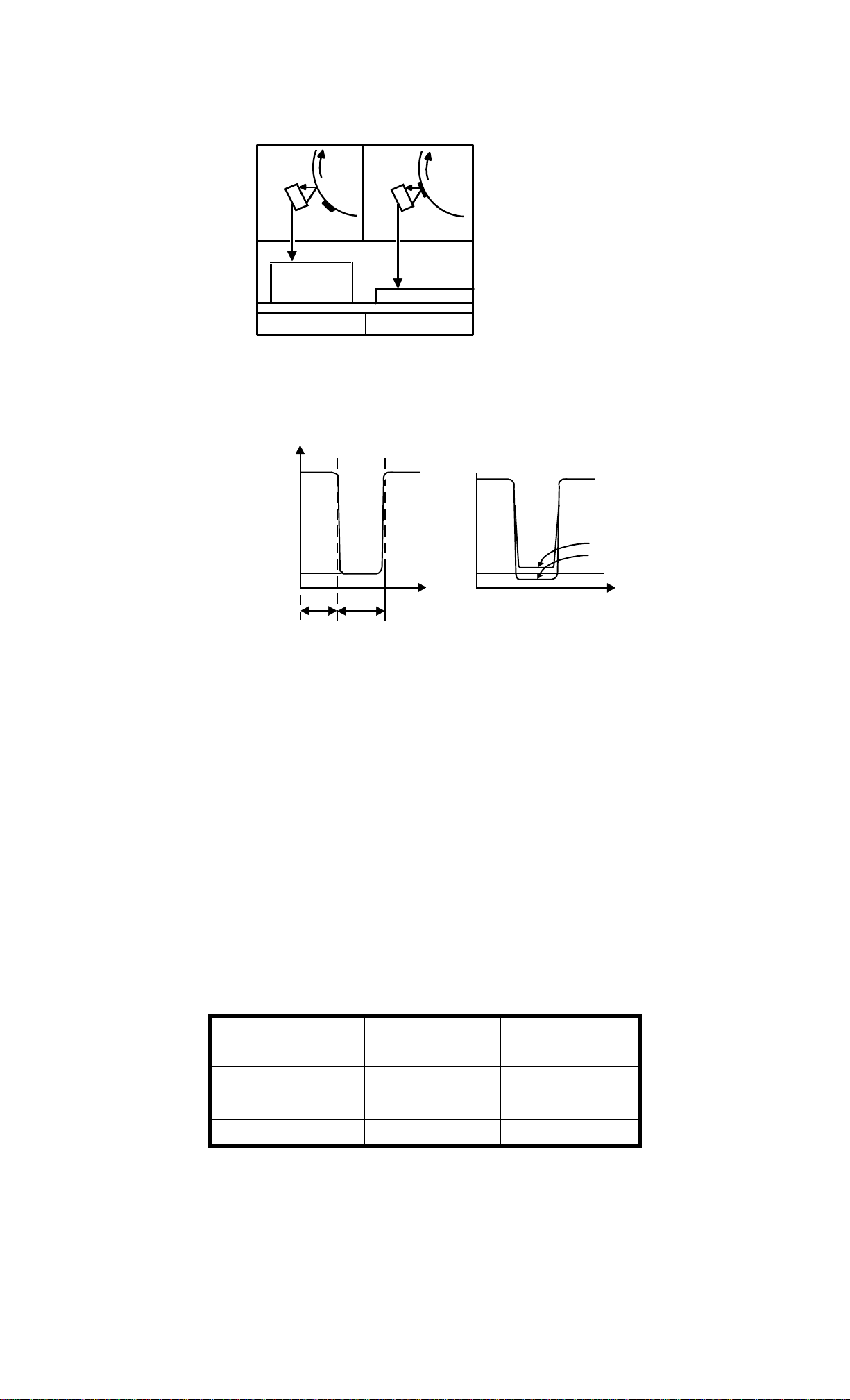
S18 Platen position Informs the CPU when the
74
platen cover is positioned.
When the angle between, the
platen cover and the exposure
glass is about 30 degrees.
S19 3rd scanner
H.P.
Informs the CPU when the 3rd
scanner is in the full size
76
position.
S20 Original length Detects the original length. 89
S21 Original width Detects the original width. 96
S22 Duplex
Detects misfeed. 109
entrance
(duplex
machine only)
STM 1-21 FT5733/5433

Symbol Name Function Index No.
S23 Duplex turn
gate (duplex
machine only)
S24 Duplex paper
end (duplex
machine only)
S25 Jogger H.P.
(duplex
machine only)
S26 LCT paper
end
S27 LCT lower
limit
S28 LCT upper
limit
Heaters
Detects the trail edge of paper
101
to determine the reverse timing
of the duplex motor and detects
misfeed.
Detects copy in the duplex tray. 102
Detects if the jogger fences are
108
at home position.
Informs the CPU when the LCT
82
runs out of paper.
Sends signal to CPU to stop
81
lowering the LCT bottom plate.
Sends signal to CPU to stop
78
lifting up the LCT bottom plate.
H1 Drum Turns on when the main switch
is off to prevent moisture
around the drum.
H2 Optics
anti-condensatio
n (option)
H3 Upper tray
(option)
Turns on when the main switch
is off to prevent moisture from
forming on the optics.
Turns on when the main switch
is off to keep paper dry in the
upper paper tray.
H4 Lower tray
(option)
Turns on when the main switch
is off to keep paper dry in the
lower paper tray.
Thermistor
TH1 Drum Monitors the temperature
around the drum.
TH2 Fusing Monitors the temperature of the
hot roller.
54
97
55
87
56
59
TH3 Optics Monitors the temperature of the
98
optics cavity.
TH4 Duplex motor
(duplex
Monitors the temperature of the
duplex motor.
104
machine only)
FT5733/5433 1-22 STM

Symbol Name Function Index No.
Thermofuse
TF1 Fusing Provides back-up overheat
61
protection in the fusing unit.
Thermoswitch
TS1 Optics Provides overheat protection in
70
the optics unit.
Noise filter
NF1 Removes electrical noise. 40
Fuse
FU1 Main (115 V
machine only)
Provides back-up high current
protection in the electrical
42
components. (125V 15 Amps)
FU2 Sorter line
(115 V
machine only)
Provides back-up high current
protection in the electrical
components of the sorter.
46
FU3 DF line (115 V
machine only)
Provides back-up high correct
protection in the electrical
7
components of the ARDF.
Circuit Breaker
CB1 (230 V
machine only)
Provides back-up high current
protection in the electrical
41
components.
Relay
RA1 Main power Controls main power. 45
Transformer
TR1 Main Steps down the wall voltage to
38
100 V ac.
Counter
CO1 Total Keeps track of the total number
86
of copies made.
STM 1-23 FT5733/5433

SECTION 2
DETAILED SECTION
DESCRIPTION

1. PROCESS CONTROL
1.1 OVERVIEW
Exposure
Lamp
Voltage
Grid
Bias
Voltage
ID Sensor Pattern
V Sensor Pattern
Toner
Supply
(Color)
Drum Thermistor
(Black)
ID Sensor
V Sensor
Development
Bias
Voltage
As seen in section 1 the copy process around the drum and the copy
image (image and background density) are controlled by many
factors.
On this copier, the following items are controlled during the copy
process to maintain good copy quality:
The exposure lamp voltage of the optics section
The grid bias voltage of the drum charge section
The development bias voltage and toner supply of the development
section
The items above use the following electrical components:
The operation panel (manual ID selection and reproduction ratio),
ADS
sensor, ID sensor, V sensor, drum thermistor, paper size switches,
color detection switches, and RAM board (drum rotation time and SP
mode data)
Refer to the process control table in the back of the Field Service
Manual for the details on which electrical component controls which
item.
In the following sections, we will explain briefly how the major
electrical components are controlled in the copy process.
STM 2-1 FT5733/5433
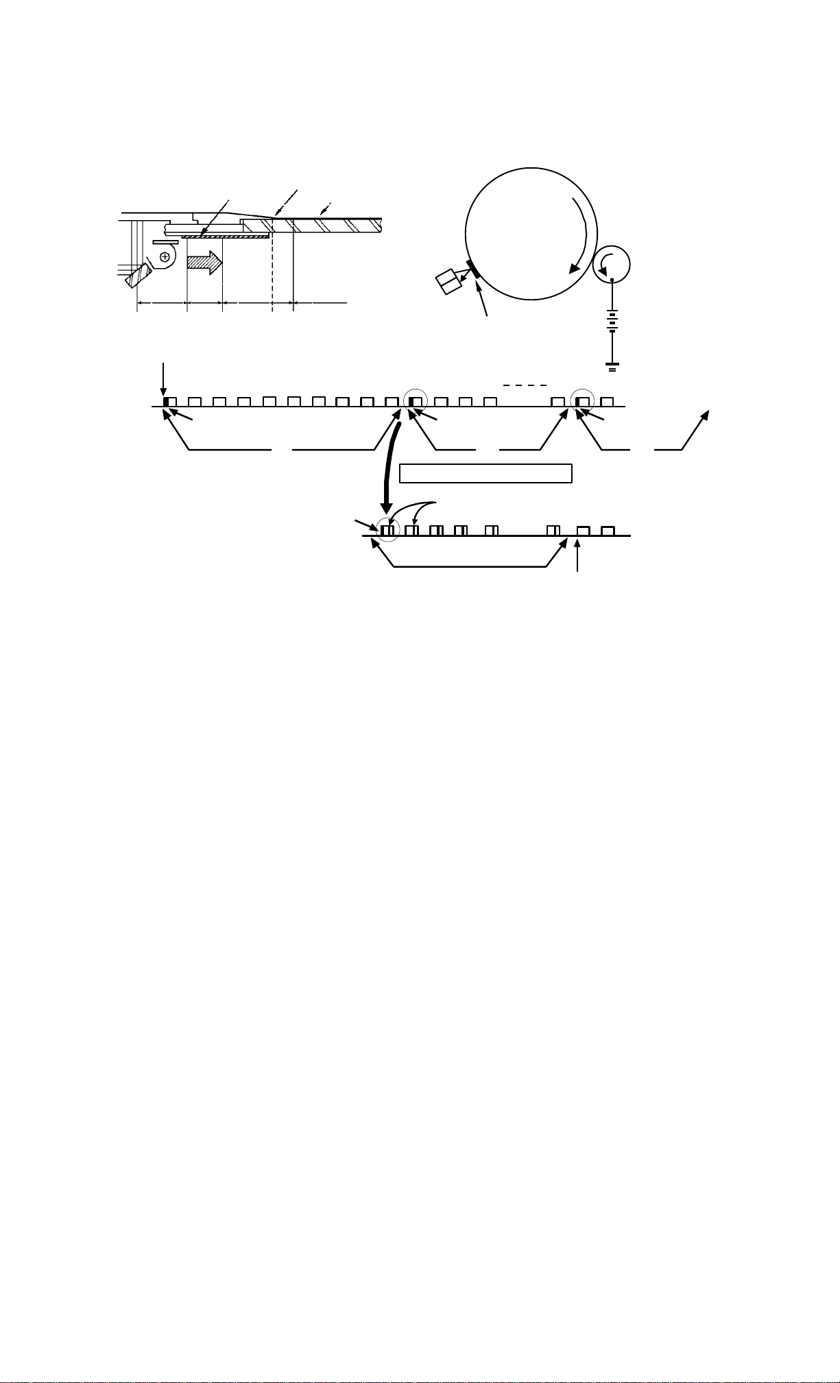
1.2 ID SENSOR CONTROL
Sensor
Original Lead Edge
Pattern
Original
OFF
ON
A B C
RAM Clear
1 2 3 4 5 6 7 8 9 10 11 12 13 14 20 21 22
Toner Density Detection Toner Density Detection Toner Density
ON
D E
OFF
Leading Edge Erase
1st
Detection
ID Sensor
Pattern
2nd 3rd
Low Toner Density
Toner Supply Timing
Toner Add
Toner Supply Clutch ON
(10 times)
Development
Bias
Detection
Detection
1.2.1 Overview
An ID (Image Density) sensor is used to control toner supply.
The sensor is located on the drum unit, under the cleaning unit.
Placing the sensor under the cleaning unit, instead of the
development unit, reduces the risk of scattered toner getting on the
sensor.
The CPU checks toner density through the ID sensor by directly
sensing the image density on the drum. This is done every 10 copy
cycles (every 5 copy cycles for the color development unit). Turning
the main switch off and on has no effect because the count is stored
in RAM. If the drum initialization is performed (SP mode #66) or the
RAM is cleared (SP mode #99), the CPU starts counting for the toner
density check from the beginning of the first copy cycle.
The ID sensor pattern (black) is positioned on the operator side of
the bottom of the left scale bracket. During the check cycle, the ID
sensor pattern is exposed prior to exposure of the original.
After the ID sensor pattern is developed, the ID sensor checks the
pattern’s reflectivity and the CPU notes it. If the reflected light is too
strong, indicating toner density is too low, toner is added to the
development unit.
FT5733/5433 2-2 STM

The toner is not added all at once. The CPU energizes the toner
supply clutch for the proper amount of time to add a calculated
amount of toner over the next 10 copy cycles (5 copy cycles for color
toner).
Such toner supply control through the ID sensor is called a detect
supply mode. On this copier, this mode is used to control both black
and color toner supply.
STM 2-3 FT5733/5433
1.2.2 ID Sensor Output
VSG = 4.0 ± 0.2
1/10 VSG = 0.4
0
(V)
LED
VSG
ON
LED
ON
VSP
VSG
1/10 VSG
0
(T)
VSP
Low image
density
High image
density
Bare
drum
Sensor
pattern
When in the toner density check cycle, the CPU receives two voltage
values directly from the ID sensor: Vsg and Vsp. Vsg is the voltage
value for the area of the drum made bare by the erase lamp unit
before the ID sensor pattern is exposed. Vsp is the voltage value for
the developed ID sensor pattern. The CPU compares these two
values to monitor the image density on the drum and with this
controls the toner supply.
Vsg is the reference voltage of the ID sensor output and is
automatically adjusted to 4V whenever SP mode #54 is called.
The development bias for the ID sensor pattern is fixed for each
toner color. This is to avoid any influence from the manual ID level
setting on toner density control. (See chart.)
[Standard
setting]
Black toner
Red/Blue toner
Green toner
0 to 500
copies
_
220 V
_
200 V
_
240 V
Over 500
copies
_
200 V
_
180 V
_
220 V
FT5733/5433 2-4 STM
 Loading...