

Page 1

FT5535/5035/4527/4027/4522/4022
FIELD SERVICE MANUAL
Page 2

IMPORTANT SAFETY NOTICES
PREVENTION OF PHYSICAL INJURY
1. Before disassembling or assembling parts of the copier and peripherals,
make sure that the copier power cord is unplugged.
2. The wall outlet should be near the copier and easily accessible.
3. Note that the drum heater and the optional anti-condensation heaters are
supplied with electrical voltage even if the main switch is turned off.
4. If any adjustment or operation check has to be made with exterior covers
off or open while the main switch is turned on, keep hands away from
electrified or mechanically driven components.
5. The inside and the metal parts of the fusing unit become extremely hot
while the copier is operating. Be careful to avoid touching those
components with your bare hands.
HEALTH SAFETY CONDITIONS
1. Toner and developer are non-toxic, but if you get either of them in your
eyes by accident, it may cause temporary eye discomfort. Try to remove
with eye drops or flush with water as first aid. If unsuccessful, get medical
attention.
OBSERVANCE OF ELECTRICAL SAFETY STANDARDS
1. The copier and its peripherals must be installed and maintained by a
customer service representative who has completed the training course
on those models.
CAUTION
!
2. The RAM board has a lithium battery which can explode if handled
incorrectly. Replace only with the same type of RAM board. Do not
recharge or burn this battery. Used RAM boards must be handled
in accordance with local regulations.
FSM a FT5535/4527/4522
Page 3

SAFETY AND ECOLOGICAL NOTES FOR DISPOSAL
1. Do not incinerate toner cartridges or used toner. Toner dust may ignite
suddenly when exposed to open flame.
2. Dispose of used toner, developer, and organic photoconductors in
accordance with local regulations. (These are non-toxic supplies.)
3. Dispose of replaced parts in accordance with local regulations.
4. When keeping used lithium batteries (from the main control boards) in
order to dispose of them later, do not store more than 100 batteries (from
the main control boards) per sealed box. Storing larger numbers or not
sealing them apart may lead to chemical reactions and heat build-up.
FT5535/4527/4522 b FSM
Page 4

SECTION 1
OVERALL MACHINE
INFORMATION
Page 5

1. SPECIFICATIONS
Configuration: Desktop
Copy Process: Dry electrostatic transfer system
Originals: Sheet/Book
Original Size: Maximum A3/11" x 17"
Copy Paper Size: Maximum
A3/11" x17" (Paper trays)
Minimum
A5/81/2" x 51/2" sideways (Paper trays)
A4/11" x 81/2" sideways (LCT)
A6/51/2" x 81/2" lengthwise (By-pass)
Duplex Copyi ng : Maximu m
A3/11" x 17"
Minimum
A5/81/2" x 51/2" (sideways)
Rev. 7/95
Copy Paper Weight: Paper tray:
52 ~ 128 g/m2, 14 ~34 lb
(A153, A155, and A156 copiers)
64 ~ 90 g/m2, 17 ~ 24 lb
(A157, A159, and A160 copiers)
By-pass:
52 ~ 157 g/m2, 14 ~42 lb
LCT:
52 ~ 128 g/m2, 14 ~ 34 lb
Duplex copyi ng :
64 ~ 105 g/m2, 17 ~ 24 lb
Reproduction Ratios: 4 Enlargement and 6 Reduction
A4/A3 Version LT/DLT Version
200%
Enlargem ent
Full size 100% 100%
Reduction
141%
122%
115%
93%
82%
75%
71%
65%
50%
200%
155%
129%
121%
93%
85%
77%
74%
65%
50%
Power Source: 120V/60Hz:
More than 12 A (for North America)
FSM 1-1 FT5535/4527/4522
Page 6

Rev. 7/95
Power Consumption:
A153, and A156 copiers A157, and A160 copiers
Copier Only Full System Copier Only Full System
Maximum 1.45 KW 1.50 KW 1.45 KW 1.50 KW
Copying 1.00 KW 1.00 KW 0.80 KW 0.80 KW
Warm-up 0.90 KW 0.92 KW 0.90 KW 0.92 KW
Stand-by 0.16 KW 0.19 KW 0.15 KW 0.17 KW
1 0.15 KW 0.17 KW 0.14 KW 0.16 KW
Energy
Saver
Auto Off 0.02 KW 0.04 KW 0.02 KW 0.04 KW
2 0.13 KW 0.15 KW 0.12 KW 0.13 KW
3 0.12 KW 0.14 KW 0.09 KW 0.10 KW
4 0.11 KW 0.12 KW 0.07 KW 0.08 KW
5 0.09 KW 0.11 KW 0.05 KW 0.06 KW
6 0.07 KW 0.09 KW – –
NOTE: 1) Full System: Copier + ADF + Paper Tray Unit + 20 Bin S/S
2) Energy Saver: See SP1-105-002
3) Auto Off: See SP5-305
A161 and A162 Copiers
Copier Only Full System
Maximum 1.45 KW 1.50 KW
Copying 0.64 KW 0.72 KW
Warm-up 0.95 KW 0.97 KW
Stand-by 0.15 KW 0.17 KW
1 0.14 KW 0.16 KW
Energy Saver
Auto Off 0.02 KW 0.04 KW
2 0.12 KW 0.13 KW
3 0.09 KW 0.10 KW
4 0.07 KW 0.08 KW
5 0.05 KW 0.06 KW
NOTE: 1) Full System: Copier + ADF + Paper Tray Unit + 10 Bin S/S
2) Energy Saver: See SP1-105-002
3) Auto Off: See SP5-305
Noise Emission:
A153, and A156 copiers A157, and A160 copiers
Copier Only Full System* Copier Only Full System*
1. Sound Power Level
Copying 66 dB(A) 68 dB(A) 61 dB(A) 67 dB(A) (L
Warm-up 41 dB(A) 41 dB(A) 39 dB(A) 40 dB(A) (L
Stand-by 41 dB(A) 41 dB(A) 39 dB(A ) 40 dB(A) (L
2. Sound Pressure Level at th e ope rator posi tion
Copying 58 dB(A) 57 dB(A) 54 dB(A) 56 dB(A) (L
Warm-up 33 dB(A) 27 dB(A) 32 dB(A) 27 dB(A) (L
Stand-by 33 dB(A) 27 dB(A) 32 dB(A ) 27 dB(A) (L
WA)
WA)
WA)
PA)
PA)
PA)
NOTE: The above measur ements are to be made according to ISO 7779.
* : Full System: Copier + ADF + Paper Tray Unit +10 Bin S/S.
FT5535/4527/4522 1-2 FSM
Page 7
Dimensions:
Width Depth Height
A153 copier 1030 mm (40.6") 655 mm (25.8") 606 mm (23.9")
A157/A161 copier 900 mm (35.5") 655 mm (25.8") 606 mm (23.9")
A156 copiers 1258 mm (49.6") 655 mm (25.8") 606 mm (23.9")
A160/A162 copiers 1128 mm (44.5") 655 mm (25.8") 606 mm (23.9")
Measurement Conditions
1) With by-pass feed table closed
2) With platen cover and copy tray attached
3) With LCT cover closed
Weight:
FT5035 A153 copier About 70 kg (154.2 lb)
FT5535 A156 copier About 82 kg (180.7 lb)
FT4027 A157 copier About 67 kg (147.7 lb)
FT4527 A160 copier About 80 kg (176.4 lb)
FT4022 A161 copier About 67 kg (147.7 lb)
FT4522 A162 copier About 80 kg (176.4 lb)
Rev. 7/95
Weight
Zoom: From 50% to 200% in 1% steps
Copying Speed (copies/minute):
A153, and A156
copiers
A157, and A160
copiers
A161, and A162
copiers
A4 sideways/
11" x 8
1/2"
35 20/19 22
27 15/14 17
22 12 -
A3/11" x 17" B4/8
Warm-Up Time A153, and A156 copiers:
Less than 110 seconds (20°C)
A157, and A160 copiers:
Less than 80 seconds (20°C)
A161, and A162 copiers:
Less than 60 seconds (20°C)
First Copy Time:
A4/11" x 8
Paper Feed Station
1st Tray 5.2 s (except for A156) 5.9 s (except for A160) 5.9 s (except for A162)
2nd Tray 5.7 s 6.6 s 6.6 s
By-pass 4.8 s 5.6 s 5.6 s
LCT 5.0 s 5.9 s 5.9 s
A153, and A156
copiers
1/2" (sideways)
A157, and A160
copiers
1/2" x 14"
A161 and A162
copiers
Note: In A156 and A160 copie rs, the 2nd tray in the above table is calle d the
1st tray (see Installation - Paper Feed Station Definition).
FSM 1-3 FT5535/4527/4522
Page 8

Rev. 7/95
Copy Number Input: Ten-key pad, 1 to 999 (count up or count down)
Manual Image Density
7 steps
Selection:
Automatic Reset: 1 minute is the standard setting; it can be changed to
a maximum of 999 seconds or no auto reset by SP
mode.
Copy Paper Capacity:
Paper Tray By-pass Feed LCT
A153 copier About 500 sheets x2 About 40 sheets –
A156 copier About 500 sheets x1 About 40 sheets About 1000 sheets
A157 copier About 250 sheets x2 About 40 sheets –
A160 copier About 250 sheets x1 About 40 sheets About 1000 sheets
A161 copier About 250 sheets x2 About 40 sheets –
A162 copier About 250 sheets x1 About 40 sheets About 1000 sheets
Duplex Tr ay Cap acity
[A156/A160/A162]:
50 sheets (30 sheets for A3/11"x17"
81 ~ 105g/m2, 21.5 ~ 27.9 lb paper)
Toner Replenishment: Cartridg e exchange (415 g /car tridge)
Toner Yield: 17K Copies/cartridge
Developer Replenisment: Type 1 (1Kg.)
Developer Yie ld: A153/A156 @ 120K
A157/A160 @ 100K
A161/A162 @ 100K
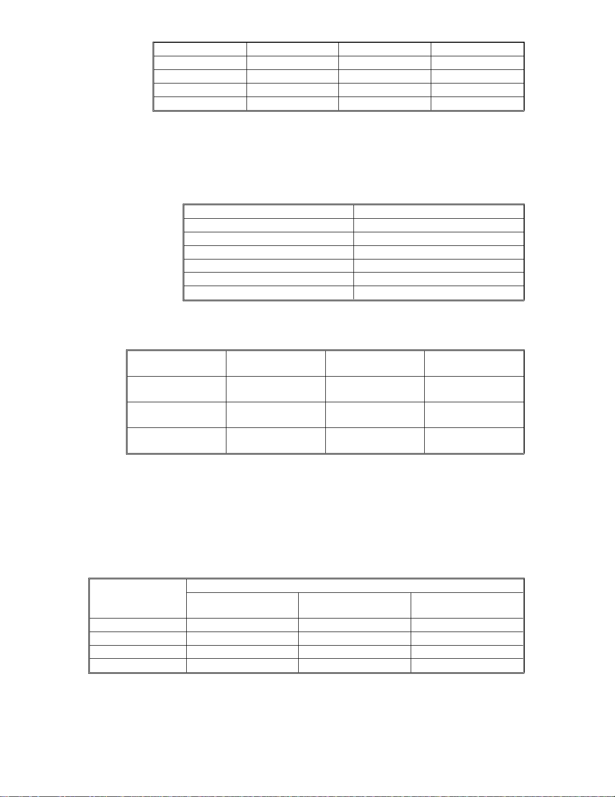
Optional Equipment: • Platen cover
• Document feeder
• Paper tray unit with two paper trays
• Paper tray unit with three paper trays
• 10 bin micro sorter
• 20 bin mini sorter
• 10 bin sorter stapler
• 20 bin sorter stapler(Not used with A161/A162 copiers)
• Sorter adapter (required when installing 20 bin
mini sorter, 10 bin sorter stapler, or 20 bin sorter
stapler for A157, A160, A161, and A162 copiers)
• Key counter
• Tray heater
• Optical anti-condensation heater
• Ori ginal lengt h sen sor for 11" x 15" size pape r
(only for LT/ DLT versi o n)
• ADS sensor for particular types of red original
• Zoom (10 Key) Function Decal *
• Margin Adjustment Function Decal*
*Not used on FT4022/4522 (A161/A162)
FT5535/4527/4522 1-4 FSM
Page 9

SECTION 2
COMPONENT LAYOUT AND
DESCRIPTION
Page 10

1. MACHINE CONFIGURATION
1.1 COPIER
Rev. 7/95
FSM 2-1 FT5535/4527/4522
Page 11
Rev. 7/95
1.2 OPTIONAL EQUIPMENT
* Only available on models FT5535 and FT4527
** Not for use on FT4022/4522(A161 /A163) copiers.
FT5535/4527/4522 2-2 FSM
Page 12
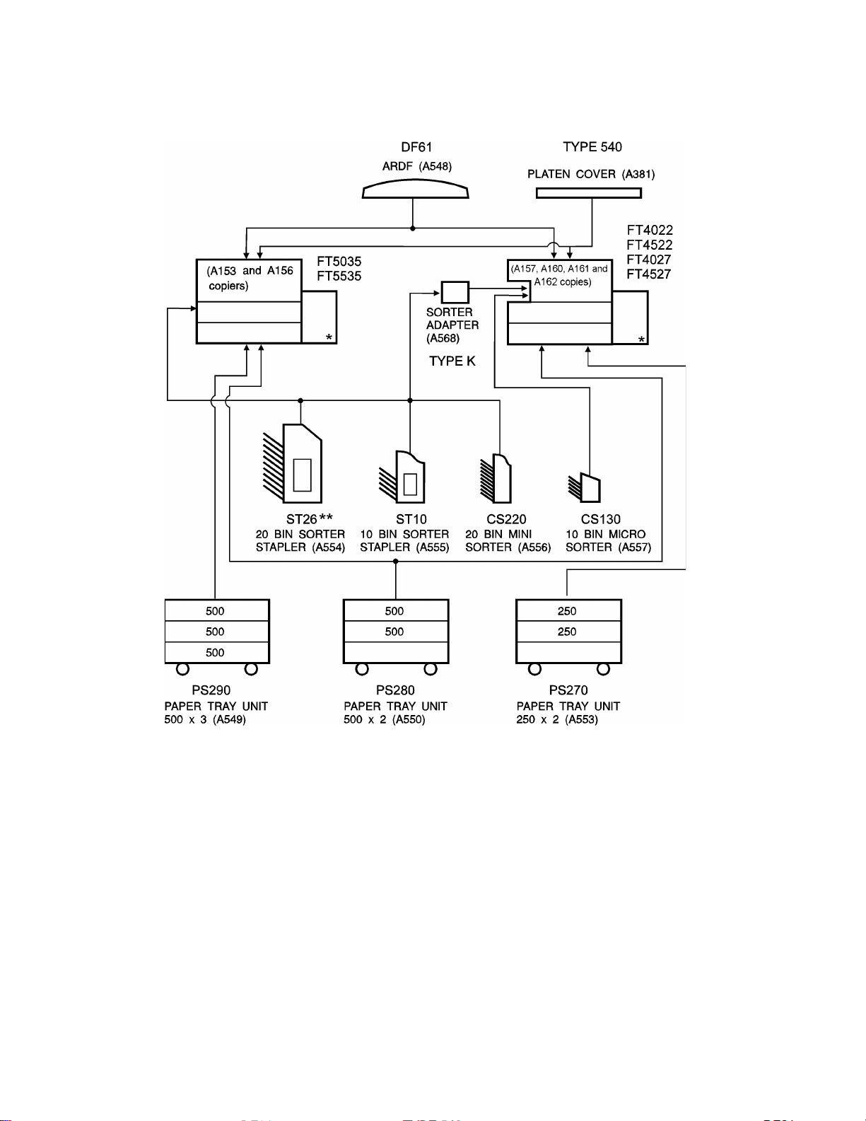
2. MECHANICAL COMPONENT LAYOUT
14
22
201918
171613
12
– A156 copier –
4
3
2
1
38
37
36
35
34
33
32
31
30
29
5
28 27 26
25
6
7
24 23
1098
11
15
21
NOTE: 1. The A153 copier is the same as the A156 copier except that the A153
does not have a duplex tray or an LCT.
2. The A155 copier is the same as the A156 copier except that the A155
does not have a duplex tray.
FSM 2-3 FT5535/4527/4522
Page 13
Rev. 7/95
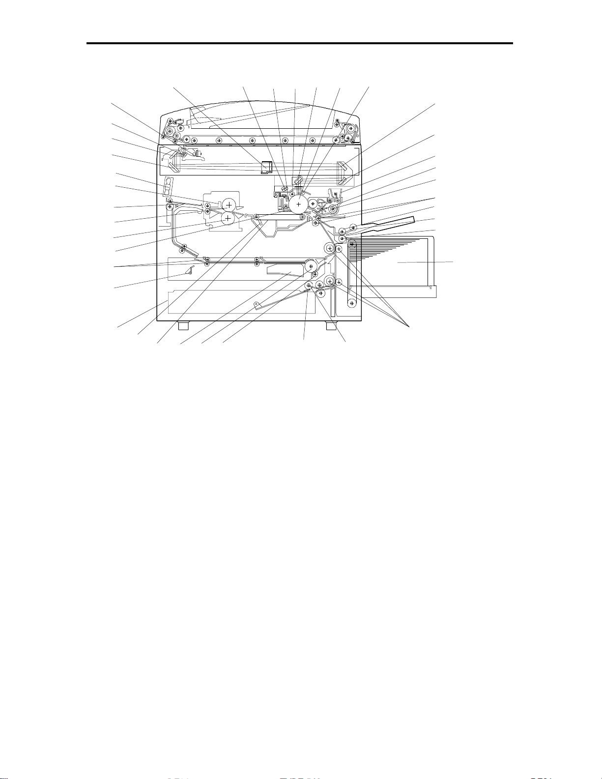
14
22
20191817161312
– A160/A162 copier –
4
3
2
1
38
37
36
35
34
33
32
31
30
5
6
7
1098
11
15
21
28
27
26
25
24
23
29
NOTE: The A157/A161 copiers are the sa me as the A160/A162 copiers e xcept
that the A157and A161 do not have a duplex tray or an LCT.
FT5535/4527/4522 2-4 FSM
Page 14

Rev. 7/95
1. 3rd Mirror
2. 2nd Mirror
3. 1st Mirror
4. Exposure Lamp
5. Lens
6. Quenching Lamp
7. Drum Cleaning Blade
8. Drum Charge Roller
9. 6th Mirror
10. OPC Drum
11. Erase Lamp
12. 4th Mirror
13. 5th Mirror
22. Vertical Transport Rollers
23. Paper Feed Roller
The roller for A153/A156
copiers is different from that
for A157/160/161/162 copiers.
24. Friction Pad
25. Duplex Friction Roller
26. Duplex Feed Roller
27. Jogger Fence
28. Transfer Belt
29. Transfer Belt Cleaning Blade
30. Lower Paper Tray
31. End Fence
32. Entrance Rollers
14. Toner Supply Unit
15. Pre-transfer Lamp
16. Development Unit
17. Registration Rollers
18. Feed Roller
19. Pick-up Roller
20. Separation Roller
21. Large Capacity Tray
33. Pick-off Pawls
34. Pressure Roller
35. Hot Roller
36. Junction Gate
37. Hot Roller Strippers
38. Transport Fan
FSM 2-5 FT5535/4527/4522
Page 15

Rev. 7/95
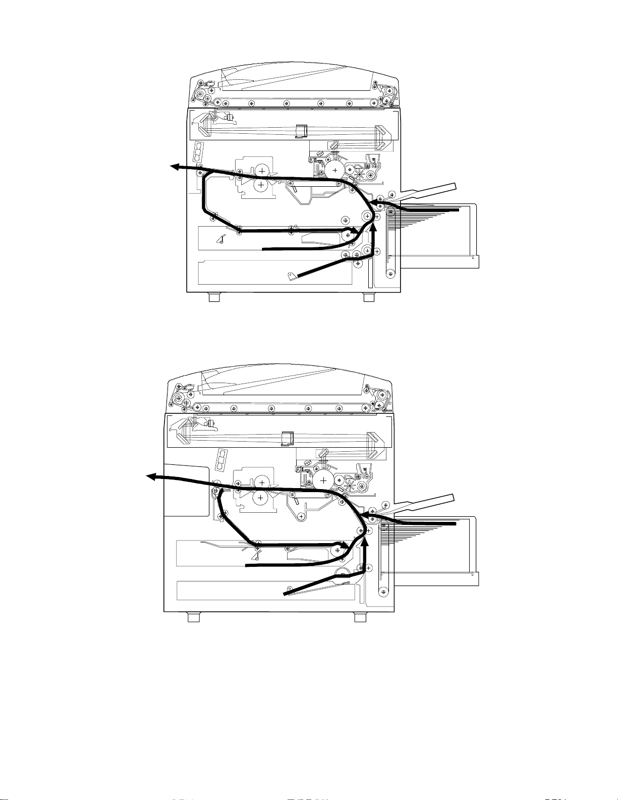
3. PAPER PATH
3.1 NORMAL COPYING
– A156 copier –
–A160/A162 copier –
FT5535/4527/4522 2-6 FSM
Page 16
Rev. 7/95
3.2 DUPLEX COPYING
– A156 copier –
– A160/A162 copier –
FSM 2-7 FT5535/4527/4522
Page 17

4. ELECTRICAL COMPONENT DESCRIPTIONS
Refer to the electrical component layout and the point to point diagram on the
waterproof pape r in the pocket for symbols and index numbers.
Symbol
Printed Circuit Boards
PCB1 14
PCB2 12
PCB3 1 1 DC Power Supply Provi des dc power.
PCB4 9 6 Main Motor Control Controls the rotation of the mai n motor.
PCB5 1
PCB6 5 5 T High Voltage Supply Supplies high voltage to the transfer belt.
PCB7 3
PCB8 8
PCB9 63
PCB10 6
PCB11 102
Motors
M1 88 Main Drives the main unit components.
M2 79
M3 97
M4 86
M5 99
M6 94 Optics Cooling Fan 1 Removes heat from the optics unit.
M7 95
M8 89 Exhaust Fan 1 Removes the heat from around the fusing unit.
M9 90
M10 92
M11 78 3rd Scanner Drive Drive s the 3rd scanner (dc stepper motor).
M12 87 Lens Vertical Drive Shifts the lens vertical position.
M13 77 Lens Horizontal Drive Shifts the lens horizontal position.
M14 58
M15 61
Ind ex
No.
Description Note
Main Control Controls all copier functio n s both directly or
through other control board s.
AC Drive Provides ac power to the exposure lamp and
fusing lamps.
CB High Voltage
Supply
Operation Panel Controls the LED mat rix, and monitors the key
Noise Filter (220 ~ 240
V machines only)
Duplex Control
(Duplex machines only)
Liqui d Cr ystal Display
(A156 machines only)
LCT Interface
(LCT machines only)
Toner Bottle Drive Rotates the toner bottle to supply toner to the
Upper Tray Lift
(A153 machines only)
Lower Tray Lift
(A153/A156 machines
only)
LCT Lift
(LCT machines only)
Optics Cooling Fan 2
(A153/A156 machines
only)
Exhaust Fan 2
(A153/A156 machines
only)
Scanner Drive Drives the 1st and 2nd scanners (dc stepper
Duplex Feed
(Duplex machines only)
End Fence Jogger
(Duplex machines only)
Supplies high voltage to the drum charge roller
and development roller.
matrix.
Removes electrical noise.
Controls the operation of the duplex tray.
Controls the guidance display and displ a ys
guidance for machine operation.
Interfaces the LCT control signal between the
main board and the LCT.
toner supply unit.
Raises the bottom plate in the upper paper tray.
Raises the bottom plate in the lower paper tray.
Lifts up and lowers the LCT bottom plate.
Removes heat from the optics unit.
Removes the heat from around the fusing unit.
motor).
Drives the feed roller and moves the bottom
plate up and down.
Drives the end fence jogger to square the
paper stack.
FT5535/4527/4522 2-8 FSM
Page 18

Symbol
Rev. 7/95
M16 60
Index
No.
Description Note
Side Fence Jogger
(Duplex machines only)
Drives the side fence jogger to square the
paper stack.
Sensors
S1 27
S2 31
S3 51
By-pass Feed Paper
Width
By-pass Feed Paper
End
Upper Tray Paper End
(Non-duplex machines
Informs the CPU what width paper is in the
by-pass feed table.
Informs the CPU that there is no paper in the
by-pass tray.
Informs the CPU when the upper paper tray
runs out of paper.
only)
Upper Relay Detects the leading edge of paper from the
S4 107
upper tray to determine the stop timing of the
upper paper feed clutch, and detects misfeeds.
S5 29
Upper Tray Upper Limit
(A153/ machines only)
Detects the height of the paper stack in the
upper paper tray to stop the upper tray lift
motor.
S6 52
Lower Tray Paper End Informs the CPU when the lower paper tray
runs out of paper.
Lower Relay Detects the leading edge of paper from the
S7 106
lower paper tray to determine the stop tim ing of
the lower paper feed clutch, and detects
misfeeds.
Detects the height of the paper stack in the
lower paper tray to stop the lower tray lift motor.
S8 30
Lower Tray Upper Limit
(A153/A156 machines
only)
S9 100
S10 26
S11 28
LCT Lower Limit
(LCT machines only)
LCT Paper End
(LCT machines only)
LCT Upper Limit
(LCT machines only)
Sends a signal to the CPU to stop lowering the
LCT bottom plat e.
Informs the CPU when the LCT run s out of
paper.
Sends a signal to the CPU to stop lifting the
LCT bottom plat e.
Registration Detects the leading edge of the copy paper to
S12 28
determine the st op timing of the paper feed
clutch, and detects misfeeds.
S13 50
S14 53
S15 39
S16 20
S17 15
S18 24
S19 21
Image Density
(ID)
Toner Density
(TD)
Lens Horizontal HP I nfor ms the CPU that the len s is at the
Lens Vertical HP Infor ms the CPU that the len s is at the full-size
Scanner HP Informs the CPU when the 1st and 2nd
3rd Scanner HP Informs the CPU when the 3rd scanner is at
Original Length-2 Detects the length of the original. This is one of
Detects the density of vario u s patterns on the
drum during proc ess control.
Detects the amount of toner inside the
development unit.
horizontal home position.
position.
scanners are at the home po sition.
the home position.
the APS (Auto Paper Select) sensors.
S20 45 Fusing Exit Detects misfeeds.
Platen Cov er Informs the CPU whether the platen cover is up
S21 16
or down (related to APS /ARE functi on s).
ARE: Auto Reduce and Enlarg e
S22 54
Toner End In structs the CPU to add toner to the toner
supply unit, and detects toner end conditions.
FSM 2-9 FT5535/4527/4522
Page 19

Rev. 7/95
Symbol
S23 43
Index
No.
Description Note
Auto Response (Not
used on A161/A162
Returns the operation panel display and exits
from the energy saver mode.
copiers
Transfer Belt ContactHPInforms the CPU of the current position of both
S24 23
the transfer belt unit and the drum charge roll er
unit.
S25 13
S26 44
S27 19
S28 56
S29 57
Auto Image Density
(ADS Sensor)
Original Width Detects the width of the original. This is one of
Original Length-1 Detects the length of the original. This is one of
Duplex Paper End
(Duplex machines only)
Duplex Turn
(Duplex machines only)
Detects the background density of each
original in ADS mode.
the APS (Auto Paper Select) sen sors.
the APS (Auto Paper Select) sen sors.
Detects paper in the duplex tray.
Detects the trailing edge of the copy paper to
determine the jogging timing, and detects
misfeeds.
S30 62
S31 59
S32 64
S33 22
Duplex Entrance
(Duplex machines only)
Side Fence Jogger HP
(Duplex machines only)
End Fence Jogger HP
(Duplex machines only)
Original Length
(Option for N.
Detects misfeeds.
Detects the home po sition of the duplex sid e
fence jogger.
Detects the home po sition of the duplex en d
fence jogger.
Detects original lengt h f or 11" x 15" paper.
American models)
Switches
SW1 33
SW2 36
By-pass Feed Table Detects whether the by-pass feed table is open
or closed.
Upper Tray
(Non-duplex machines
Detects whether the upper paper tray is in
place or not.
only)
SW3 35
SW4 104
SW5 25
Lower Tray Detects whether the lower paper tray is in
place or not.
Tray Down
(LCT machines only)
Upper Tray Paper Size
(Non-duplex machines
Sends a signal to the CPU to lower the LCT
bottom plate.
Determine s what size of paper is in the upper
paper tray.
only)
SW6 34
SW7 32
Lower Tray Paper Size Determin e s what size of paper is in the lower
paper tray.
Vertical Guide Set
(Non-LCT machines
Detects whether the vertical guide is open or
not.
only)
SW8 105
SW9 103
LCT Cover-1
(LCT machines only)
LCT Cover-2
(LCT machines only)
Detects whether the LCT cover is open or not.
Cuts the dc power line of the LCT lift motor.
SW10 42 Main Supplies power to the copier.
SW11 41
SW12 48
Front Cover Safety Detects whether the front door is open and via
relays cuts the ac power.
Exit Cover Safety
Detects whether the exit cover is open or not.
(A157/A160 machines only)
FT5535/4527/4522 2-10 FSM
Page 20

Symbol
Index
No.
Description Note
Magnet ic Clu tch e s
CL1 72
Toner Supply Turns the toner supply roller to supply toner to
the development unit.
CL2 71 Development Drives the development roller.
CL3 93
Transfer Belt Contact
(1/3 Turn Clutc h)
Controls the touch and release movement of
both the transfer belt unit and the drum charge
roller unit.
CL4 73 Registration Dri ves the registration rollers.
CL5 74
By-pass Feed Starts paper feed from the by-p ass feed table
or LCT.
CL6 76 Relay Drives the relay rollers.
Starts paper feed f rom the upper paper tray.
CL7 84
Upper Paper Feed
(Non-duplex machines
only)
CL8 85
Lower Paper Feed Starts paper feed from the lower paper tray.
Solenoids
Picks paper up from the by-pass feed table.
When paper is fed from the LCT, this solenoid
assists SOL3.
SOL1 75
LCT machines:
LCT/By-Pass Pick-up
Solenoid
Non-LCT machines:
By-pass Pick-up
Solenoid
SOL2 91
SOL3 98
SOL4 80
SOL5 82
Junction Gate
(Duplex machines only)
LCT Pick-up
(LCT machines only)
Upper Tray Pick-up
(A153 machines only)
Lower Tray Pick-up
(A153/A156 machines
Moves the juncti on gate to dir ect copi e s to the
duplex tray or to the paper exit.
Picks up paper from the LCT.
Controls the up/down movement of the pick-up
roller in the upper paper tray.
Controls the up/down movement of the pick-up
roller in the lower paper tray.
only)
SOL6 81
Upper Tray Separation
(A153 machines only)
Controls the up-down movement of the
separation roller in the upper paper tray feed
station.
Controls the up-down movement of the
separation roller in the lower paper tray feed
station.
SOL7 83
Lower Tray Separation
(A153/A156 machines
only)
Lamps
L1 17
L2 65
Exposure Applies high intensity light to the origi nal for
exposure.
Main Fusing P rov id e s heat to the central area of the hot
roll e r .
L3 66 Secondary Fusing Provides heat to both ends of the hot roller.
Pre-transfer Reduces the charge remaining on the drum
L4 4
surface before transfer.
Quenching Neutralizes any charge remaining on the drum
L5 5
surface after cleaning.
Erase After exposure, this eliminates the charge on
L6 2
area s of the drum that will not be used for the
image.
FSM 2-11 FT5535/4527/4522
Page 21

Symbol
Heaters
H1 38
H2 46
H3 37
Thermistors
TH1 69
TH2 70
TH3 47 Optics Moni tor s the temper ature of the optics cavity.
TH4 49
Thermofuses
TF1 68
TF2 67
TF3 18
Counters
CO1 40 Total Keeps track of the total number of copies made.
CO2 N/A
Others
CB1 9
CC1 10 Choke Coil Removes high frequency current.
TR1 7
Index
No.
Description Note
Drum Turns on when the main switch is off to keep
the temperature around the drum charge rolle r
at a certai n lev el . Also prevents moist ure f rom
formi ng around the drum .
Optics
Anti-condensation
(option )
Lower Tr a y
(option)
Main Fusing Monitors the temperature at the central area of
Secondary Fu sing Monitor s the tempe r ature at the ends of the hot
Drum Charge Monitors the temperature of the drum char g e
Main Fusing Provides back-up overheat protection in the
Secondary Fusing Provides back- up over heat protec tion in the
Exposure Lamp Opens the exposure lamp circuit if the 1st
Key
(option )
Circuit Breaker
(220 ~ 240V machines
only)
Transformer
(220 ~ 240V machines
only)
Turns on when the main switch is off to prevent
moisture from forming on the optics.
Turns on when the main switch is off to keep
paper dry in the lower paper tray.
the hot roller.
roller.
roller.
fusing unit.
fusing unit.
scanner overheats.
Used for control of authorized use. The copier
will not operate until it is installed.
Provides back-up high current protection for
electrical components.
Steps down the wall voltage to 100 Vac.
FT5535/4527/4522 2-12 FSM
Page 22

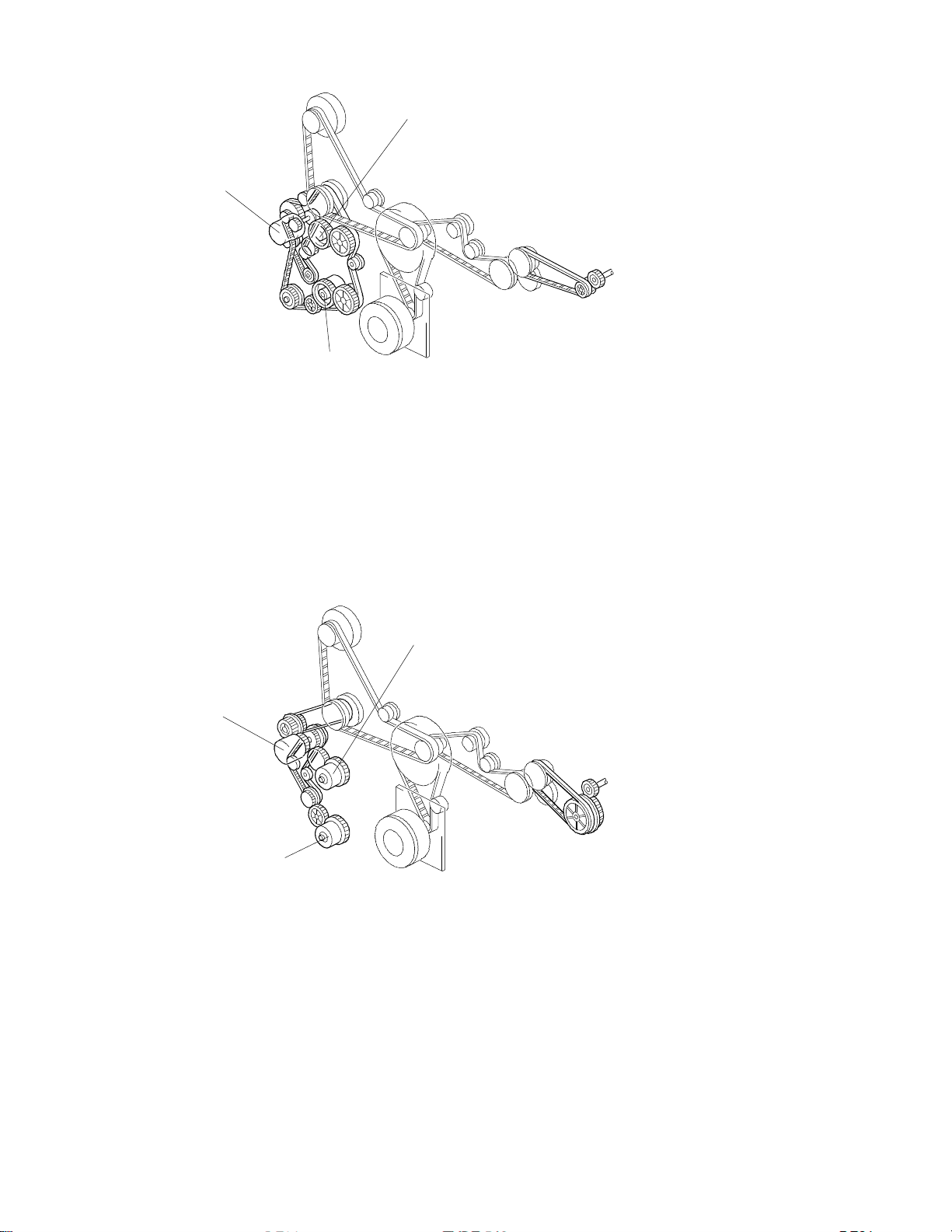
5. DRIVE LAYOUT
3
4
6
5.1 ALL MODELS
13
12
11
10
1
9
8
2
5
7
1. Drum Drive Pulley
2. Drum Charge Roller Drive Gear
3. Transfer Belt Contact Clutch
Gear
4. Scanner Drive Motor
5. Scanner Drive Pulley
6. Transfer Belt Drive Gear
7. Fusing Unit Drive Gear
8. Main Motor
9. Main Pulley
10. Registrati o n Clut ch Ge ar
11. By-pass Feed Clut ch Gear
12. Development Drive Clutch Gear
13. Toner Supply Clu t ch Gear
FSM 2-13 FT5535/4527/4522
Page 23
Rev. 7/95
5.2 A153/A156
1
3
2
1. Upper Paper Feed Clutch Gear (A153/A15 5 only)
2. Lower Paper Feed Clutch Gear
3. Relay Clutch Gear
5.3 A157/A160/A161/A162
1
3
2
1. Upper Paper Feed Clutch Gear (A157and A161 only)
2. Lower Paper Feed Clutch Gear
3. Relay Clutch Gear
FT5535/4527/4522 2-14 FSM
Page 24

SECTION 3
INSTALLATION
Page 25

Rev. 7/95
1. INSTALLATION REQUIREMENTS
1.1 ENVIRONMENT
1. Temperature Range: 10°C to 30°C (50°F to 86°F)
2. Humidity Range: 15% to 90% RH
3. Ambient Illu mina ti on: Less than 1,500 lux (do not expose to direct
sunlig ht.)
4. Ventilation: Room air should turn over at least 3 m3/hr/person
5. Ambient Dust: Less than 0.10 mg/m3 (2.7 x 10⁻⁶ oz/yd3)
6. If the place of installation is air-conditioned or heated, place the machine:
a) where it will not be subjected to sudden temperature changes.
b) where it will not be directly exposed to cool air from an air conditioner.
c) where it will not be directly exposed to heat from a heater .
7. Do not place the machine where it will be exposed to corrosive gases.
8. Do not install the machine at any location over 2,000 m (6,500 feet) above
sea level.
9. Place the copier on a strong and level base.
10. Do not place the machine where it may be subjected to strong vibrations.
1.2 MACHINE LEVEL
1. Front to ba ck: Within 5 mm (0.2") of level
2. Right to left: Within 5 mm (0.2") of level
FSM 3-1 FT5535/4527/4522
Page 26

1.3 MINIMUM SPACE REQUIREMENTS
Place the copier near the power source, providing clearance as shown:
More than 10 cm/4.0"
More than
39 cm/15. 4"
NOTE: *1. In machines without an LCT, the di stan ce bet ween the wall
and the edge of the by-pass feed table must be more than 28.5
cm/11.3".
REAR
(See Note *2)
Your machine
FRONT
More than 70 cm/27.6"
More than
28.5 cm/11.3"
(See Note *1)
*2. Copier only + Receiving Tray
103.0 c m/40.6 " (with L CT: 125. 8 cm/49. 6")
Copier + A554 Sorter/Stapler
103.2 c m/40.7 " (with L CT: 126. 0 cm/49. 7")
Copier + A555 Sorter/Stapler
100.1 c m/39.5 " (with L CT: 122. 9 cm/48. 4")
Copier + A556 Sorter
96.6 cm/38.1" (with LCT: 119.4 cm/47.1")
FT5535/4527/4522 3-2 FSM
Page 27

1.4 POWER REQUIREMENTS
CAUTION
!
A. Be sure to ground the machine.
B. Make sure the plug is firmly inserted in the outlet.
C. Avoid m ulti-wiring.
1. Input voltage level:
120V/60Hz: More than 12 A (for North America)
220V~240V/50Hz: More than 7 A (for Europe)
220V/50Hz: More than 7 A (for Asia)
110V/60Hz: More than 12 A (for Taiwan)
220V/60Hz: More than 7 A (for Saudi Arabia, Philippines)
2. Permissible voltage fluctuation: 10%
3. Do not set anything on the power cord.
FSM 3-3 FT5535/4527/4522
Page 28

2. COPIER INSTALLATION
2.1 ACCESSORY CHECK
Check the quantity and condition of the accessories in the box against the
following list:
Description Qty
1. Paper Size Decal.....................................................................................1
2. Symbol Explanation Decal (except for the A156 copier).........................1
3. Optional Zoom Function Decal................................................................1
4. Optional Margin Adjustment Function Decal...........................................1
5. Combine Originals Explanation Decal (exce pt for the A156 copi er ).......1
6. Receiving Tray.........................................................................................1
7. Operating Instructions (except for –27 machines)............... .... ................1
8. User Survey Card (–17 machine s only)....... ........................ .... .... ............1
9. New Equipment Condition Report...........................................................1
FT5535/4527/4522 3-4 FSM
Page 29
2.2 COPIER INSTALLATION PROCEDURE
- A153/A155/A156 copiers -
[C]
Rev. 7/95
[A]
[B]
- A157/A159/A160 copiers -
[C]
[A]
[B]
[E]
[D]
- A155/A156/A159/A160 copiers -
[E]
[D]
CAUTION
Never lift the machine by holding the LCT, or the LCT will break.
NOTE:(1) Keep the shipping retainers after installing the machine. They will be
reused if the machine is moved to another location in the future.
(2) Proper rei nsta l lati on of the shippi n g retai ners is required in order to
avoid any transport d a mage. It is most impor tant to put back the
scanner lock pin when transporting this copier. If not, skewed image
may result.
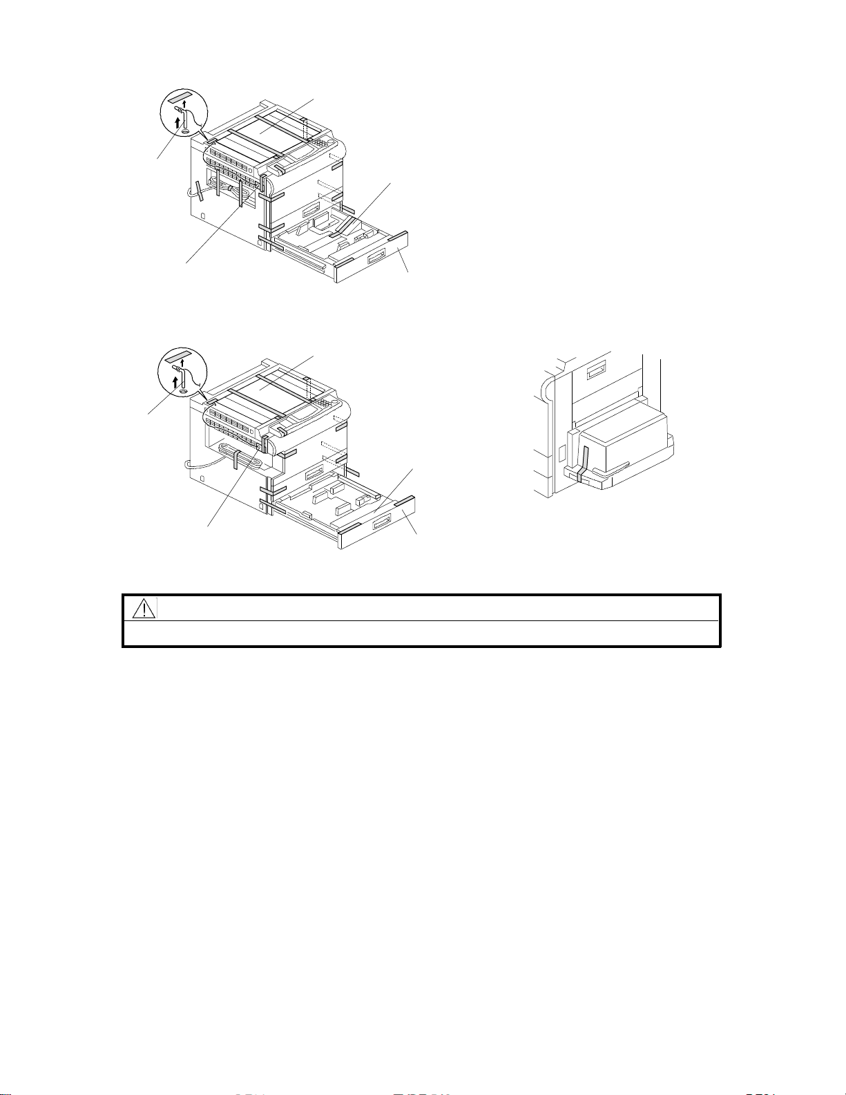
1. Remove the scanner lock pin [A] and red tag [B] as shown.
2. A155/A156/A159/A160 copiers onl y: Remove the strips of tape and the
sheet of paper [C]. Also, remove the strip of tape on the LCT.
3. Pull out the paper tray [D], and remove the strips of tape and the bottom plate
stopper [E]. Then install the paper tray in the copier (1 tray for duplex
machines and 2 trays for non-duplex machines).
FSM 3-5 FT5535/4527/4522
Page 30
- A156 copier -
[H]
[H]
[F]
[I]
[D]
[C]
[G] [B]
[F]
- A160 copier -
[F]
[I]
[B]
[E]
[C]
[A]
[B]
[D]
[G] [B]
[F]
[E]
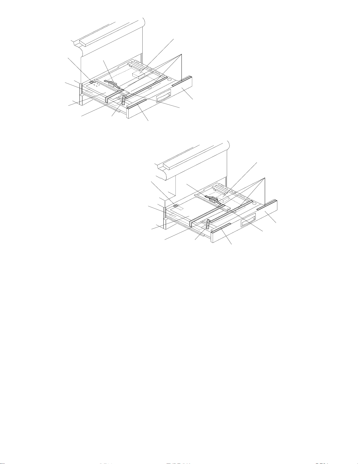
4. A156/A160 copiers only:
1) Pull out the duplex tray [A] and remove the strips of tape [B].
2) Remove the guide roller stopp er [C] and a sheet of paper [D].
3) Open the upper duplex guide plate [E] and remove the strips of tape [F].
4) Open the low er dupl e x guide plate [G], and re move the styrofoam support
[H] and the sheet of paper [I].
5) Install the duplex tray in the copier.
[A]
FT5535/4527/4522 3-6 FSM
Page 31

- A153/A155/A156 copiers -
[C]
[A]
[B]
- A157/A159/A160 copiers -
[C]
[B]
[B]
[A]
[F]
[G]
[E]
[D]
5. Open the front cover and swing out the toner bottle hold er [A].
6. Remove the strips of tape [B].
7. Remove the switch actuator lock bracket [C] as shown.
8. Turn the "A1" lever [D] counterclockwise to lower the transfer belt unit. Then
remove the cushion sheet [E].
9. Remove the blade release wedge [F] together with the pick off pawl release
mylar [G].
10. Return the "A1" lever to the set position.
FSM 3-7 FT5535/4527/4522
Page 32

Rev. 7/95
[D]
[B]
[A]
[C]
[H]
[F]
[E]
[G]
11. Remove the knob screw [A].
12. á Swing out the bottle holder [B] and í pull down the lock lever [C].
ó Then slide out the bottle holder assembly [D] and ú swing out the bottle
holder assembly [D].
13. Remove the knob screw [E] and disconnect the white connector [F].
14. Pull down the development unit lock lever [G] from under the plate and pull
out the development unit [H]. Then place it on a clean sheet of paper.
FT5535/4527/4522 3-8 FSM
Page 33

[B]
[A]
[F]
[E]
[C]
[D]
15. Disconnect the connector [A] and separate the toner supply unit [B] from the
development unit (2 screws).
16. Pour about half a pack of develope r [C] int o the devel o p ment unit . Then
rotate the outer gear [D] as shown to distribute the developer evenly. T hen
pour in all the remaining developer and rotate the gear again.
NOTE: T o prevent the developer from spilling, do not rotate the gears in the
other dire cti on.
17. Remount the toner supply unit on the development unit (2 screws) and
connect the white connector .
NOTE: Make sure that the positioning rib [E] sits in the groove [F].
18. Install the development unit in the copier (1 knob screw and 1 connector).
FSM 3-9 FT5535/4527/4522
Page 34

Rev. 7/95
[C]
[D]
[A]
[B]
19. Swing in the bottle holder assembly [A] so that the toner bottle holder [B] and
the slide rail [C] are aligned straig ht.
IMPORTANT: Do not swing the bottle holder into the machine before doing
step 20.
20. Slide the bottle holder a ssembly in as described below:
1) Slide the bottle holder assembly into its lock position while pressing down
the bottle holder lock lever [D].
2) When the bottle holder assembly reaches its lock position, push up the
bottle holder lock lever so that the knob screw holes are aligned.
3) Secure the bottle holder lock lever with the knob screw.
CAUTION
Do not swing the bottle holde r assembly al l the way into its origi nal
position in the machine wit ho ut sliding a nd locki ng it into posit io n exact l y
as described above. Otherwise, the assembly will be damaged.
21. Install a toner bottle by fo llowing the instructions placed on the reverse side of
the front cover.
22. Swing in the toner bottl e hold er to its original posi tion and close the front
cover.
23. Plug in the copier and turn on t he main switch.
FT5535/4527/4522 3-10 FSM
Page 35

24. Enter SP mode as follows:
1) Press the "Clear Modes" key.
2) Enter "107" using the numeric keys.
3) Hold down the "Clear/Stop" key for more than 3 seconds.
NOTE: When SP mode is selected, "1" blinks in the 3rd digit of the copy
counter, the Auto I mage Density indi cat or star ts blin ki ng, and the
reduce/enlarge indicator turns off.
25. Perform the "TD sensor initial setting" SP mode as fol lows:
1) Enter "2" and press the "Enter" key.
Rev. 7/95
2) Enter "214" and press the "Enter" key.
3) Press the "Start" key.
NOTE: The machine will auto matically stop when TD sensor initia l setti ng is
completed. (It takes abou t 2.5 minute s.)
26. Perform the "Compulsory toner supply" SP mode as follows:
1) Press the "Clear Modes" key twice.
2) Enter "2" and press the "Enter" key.
3) Enter "207" and press the "Enter" key.
4) Press the "Start" key.
NOTE: The machine will auto matically stop when c o mpulsor y toner suppl y is
completed. (It takes abou t 30 seconds.)
5) Compulsory toner supply must be performed twice in order to supply
enough toner to the toner hopper, so press the "Start" key again.
- A156 copier only -
Select the proper language for the guidance display as follows:
1) Press the "Clear Modes" key twice.
2) Enter "5" in the 3rd digit of the copy counter and pre ss the "Enter" key.
3) Enter "910" and press the "Enter" key.
4) Enter the nu mber for the desir ed langu age in th e three -dig i t indi cator and
press the "Enter" key.
1:English 2:French 3:German 4:Italian 5:Spanish
6:Swedish 7:Portuguese 8:Danish 9:Norwegian 10:Finnish 11:Dutch
27. Press the "Clear Modes" key three times to exit SP mode.
FSM 3-11 FT5535/4527/4522
Page 36

[B]
[A]
[D]
[C]
[E]
On the paper tray
On the duplex tray
28. Pull out the paper tray and load paper into it. (The paper size and direction for
each tray should be as specified by the customer.)
NOTE: T he side and rear fences should be properly positioned.
29. Select the appropr i ate pape r size for the paper trays in the main body by
sliding the paper size slider into the correct position (see section 2.3.2 "Paper
size selection for the copier paper trays" for details).
30. When a paper tray unit is installed: Enter the proper paper size for each
paper tray by following the proced ure shown in section 2.3, "Pape r Size
Selection" and in "Servi ce Table s - SP5-019 : Paper Size Setti ng ".
31. Load paper into the paper trays and the copy tray.
32. Attach the appropr iate paper si ze decals [A] to the paper trays.
Also (A156/A160 copiers only), attach the duplex decal to the duplex tray.
NOTE: Paper size decals are used also for the paper tray unit. Save the
remaining decals for use with the paper tray unit.
33. Install the optional platen cover [B] as follows if necessary:
1) Install 2 stud screws [C] on the top cover as shown.
2) Position the platen cover bracket [D] on the stud screws and slide it to the
left.
34. All models except the A156: Attach the symbol explanation decal [E] to the
top cover as shown. (If the ARDF will be installed, stick the decal on the
ARDF exit cover. Refer to the ARDF installation pro cedure.)
35. Check the copy quality and machine operation.
FT5535/4527/4522 3-12 FSM
Page 37

2.3 PAPER SIZE SELECTION
By-pass Feed
Copier
Paper Tray Unit
LCT
2.3.1 Paper Feed Station Definition
A153 and A157 copiers
By-pass Feed
A155 and A159 copiers
1st tray
2nd tray
3rd tray
4th tray
5th tray*
A156 and A160 copiers
By-pass Feed
1st tray
2nd tray
3rd tray
4th tray*
LCT
Copier
Paper Tray Unit
Copier
Paper Tray Unit
1st tray
2nd tray
3rd tray
4th tray
5th tray*
The diagrams on this page
show how the paper feed
stations are numbered in the
various models.
NOTE: *A549 paper tray unit only
FSM 3-13 FT5535/4527/4522
Page 38

2.3.2 Paper Size Selection for Copier Paper Trays
[A]
For the 1st tray and 2nd tray for A153, A155, A157, and A1 59 copier s, and the
1st tray for A156 and A160 copiers, slide the paper size slider [A] to the paper
size indicati on that matches the paper size in the tra y. T he following paper sizes
can be selected with the paper size slider .
A4/A3 Version LT/DLT Version
A3 (lengthwise) 11" x 17"
B4 (lengthwise) 8
A4 (lengthwise) 81/2" x 11"
A4 (sideways) 11" x 8
B5 (lengthwise) A4 (lengthwise)
B5 (sideways) A4 (sideways)
A5 (sideways) 8
8
1/2" x 11" 11" x 15"
11" x 8
11" x 17" F4 (8
F4 (8
1/2" 10" x 14"
1/2" x 13") (lengthwise) 8" x 10"
1/2" X 14"
1/2"
1/2" x 51/2"
1/2" x 13") (lengthwise)
NOTE: For the 1st tray, a wider range of paper sizes can be selected with SP
mode. See section 2.3.4 and "Service Tables - SP5-019: Paper Size
Setting".
FT5535/4527/4522 3-14 FSM
Page 39

2.3.3 Pa per Size Select io n for the Paper T ray Unit, LCT , and By-pass Feed
For the paper tray unit, LCT and by-pass feed, select the paper size with SP
mode (SP5-019) using the following procedure.
1. Enter SP mode as follows;
1) Press the "Clear Modes" key.
2) Enter "107" with the numeric keys.
3) Hold down the "Clear/Stop" key for more than 3 seconds.
NOTE: When SP mode is selected, "1" blinks in the 3rd digit of the copy
counter, the Auto I mage Density indi cat or star ts blin ki ng, and the
reduce/enlarge indicator turns off.
2. Enter SP5-019 as follows
1) Enter "5" and press the "Enter" key.
2) Enter "019" and press the "Enter" key.
3. Press the or key until the requi re d 3rd level progr am number is
selected.
3rd level (001~008
can be selected with
keys.
SP5-019-001 ——————
SP5-019-002 ————
SP5-019-003
SP5-019-004
SP5-019-005
SP5-019-006
SP5-019-007
SP5-019-008 — —
A153/A157 copiers A155/A159 copiers A156/A160 copiers
Paper
Tray
Indicator
3
4
5
1
Paper
Size
Selection
3rd Tray
4th Tray
5th Tray
By-pass
Feed
SPECIAL*
Paper
Tray
Indicator
3
4
5
T
1
Paper
the and
Size
Selection
3rd Tray
4th Tray
5th Tray
By-pass
Feed
LCT
*SPECIAL — —
Paper
Tray
Indicator
2
3
4
T
1
Paper
Size
Selection
2nd Tray
3rd Tray
4th Tray
By-pass
Feed
LCT
SPECIAL*
Example: In an A155 copier, to select the paper size for the LCT, select 3rd level
program 007.
NOTE: The 3rd level program number is blinking in the 1st digi t of the cop y
counter.
Depending on the 3rd level program number, the paper tray indicator
changes.
SP settings for each 3rd level program number are blinking in the
reduce/enlarge indicator.
*SPECIAL: See section 2.3.4 and "Service Tables - SP5-019: Paper Size
Setting" for how to select from a wider range of paper sizes for the 1st tray.
FSM 3-15 FT5535/4527/4522
Page 40

4. Select the required SP setting with the numeric keys (see Service Tables Paper Size Settings), then press the "Enter" key.
NOTE: If you input the wrong setti ng by mistake, you can cancel it by
pressing the "Clear/Stop" key before pressing the "Enter " key.
5. Leave SP mode by pressing the "Clear Modes" key three times.
2.3.4 Special Paper Size Selection for the 1st Tray
For the 1st tray, a wider range of paper sizes can be selected using SP5-019-007
for A153, A156, A157 and A160 copiers, or SP5-019- 008 for A155 and A159
copier s.
NOTE: The definition of the 1st tray differs with the type of copier. See section
2.3.1 "Paper Feed Station Definition".
If a special paper size is selected, the machine ignores the pape r size set with
the paper size slider .
See Service Tables - Paper Size Settings for how to select a special paper size
using SP5-019.
FT5535/4527/4522 3-16 FSM
Page 41

2.4 SORTER ADAPTER INSTALLATION
(OPTION FOR A157, A159, AND A160 COPIERS ONLY)
2.4.1 Accessory Check
Check the quantity and condition of the accessories in the box against the
following list.
Description Qty
1. Installation Procedure..............................................................................1
2. Sorter Adapter Front Cover .....................................................................1
3. Clip...........................................................................................................3
4. Philips Pan Head Screw M4 x 6 .......... .... ................................................4
FSM 3-17 FT5535/4527/4522
Page 42

2.4.2 Installation Procedure
[E]
[A]
[B]
[C]
[G]
[F]
[D]
1. Remove the cover plate [A] (2 screws).
2. Remove the three plastic caps [B] from the copier left cover with nippers.
3. Install the sorter adapter [C] (4 tapping screws) in the paper exit section of
the copier.
4. Attach the sorter adap ter front cover [D] to the copier front cover (3 clips [E])
as shown.
NOTE: Be sure to push the clips in completely.
5. Check that the rotation of the exit rollers [F] is synchr onized with the rotation
of the fusing unit knob [G].
FT5535/4527/4522 3-18 FSM
Page 43

2.5 TRAY HEATER INSTALLATION (OPTION)
[H]
Rev. 7/95
[A]
[E]
[K]
[B]
[D]
[J]
[C]
[F]
[G]
[I]
[L]
[M]
[J]
NOTE: The optio nal tray heater keeps copy paper dry. In humid environments,
copy paper may crease as it comes out of the fusing unit. The heater is
available as a service part. (See the parts catalog.)
CAUTION
Unplug the copier power cord before starting the following procedure.
If the 20 bin sorter stapler (A554) has been already installed, do step 1.
1. Remove the 20-bin sorter stapler and the sort er stapl e r mounti ng fra me fro m
the copier. (See "20-BIN SORTER STAPLER INSTALLATION
PROCEDURE".)
2. A153, A155, A157, and A159 copie rs: R e move the 1st and 2nd paper trays.
3. A156 and A160 copiers: Remove the duplex unit and the 1st paper tray.
FSM 3-19 FT5535/4527/4522
Page 44

Rev. 7/95
4. Remove the rear cover. (See "Replacement and Adjustment - Inner and
Outer Covers".)
5. Pull out the carrying handles [A].
6. Before installing the heat er, bind the heater harness [B] with i nsul ating tape
[C] as shown to prevent the heater harness from being damaged by the edge
of the copier main frame.
7. Pass the connector [D] through the opening [E] in the copier main frame.
8. Mount the heater [F] on the bottom of the copier main fra me (2 screws).
9. Pass the two projection s [G] throug h the opening [H] in the copier main
frame, then mount the heater cover [I] on the bottom of the copier main frame
(1 screw).
CAUTION
The heater cover is necessary, because the surface of the heater
becomes very hot.
10. Insert the clamp [J] into the rear frame, and join the connectors [K].
11. Clamp the harness [L] to the two clamps [J] and [M] as shown to prevent the
harness from touching the carrying handle.
NOTE: Tell the customer that even when the copier main switch is turned off,
the copier power cord should be plugged in. Otherwise, the tray
heater will not functi on .
FT5535/4527/4522 3-20 FSM
Page 45

2.6 OPTICS ANTI-CONDENSATION HEATER (OPTION)
[E]
[B]
[G]
[A]
[F]
Rev. 7/95
[H]
[C]
[D]
NOTE: The optics anti - cond ensation heater keeps water from condensing on the
copier’ s mirrors.
Such condensation occurs at cold tempe rature s with high humidity, and
causes the first few copies of the day to be dark, or even black.
The heater is availabl e as a service par t. (See the part s catalog.)
CAUTION
Unplug the copier power cord before starting the following procedure.
1. Remove the exposure glass. (See "Replacement and Adjustme nt - Exposure
Glass Removal".)
2. Remove the rear cover. (See "Replacement and Adjustment - Outer Cover
Removal".)
3. Insert the two clamps [A] as shown.
4. Mount the anti-conde nsation heater [B] (2 screws).
5. Pass the connector [C] through the opening [D].
6. Clamp the harness [E] to the two clamps [A].
FSM 3-21 FT5535/4527/4522
Page 46

7. Connect the red two-pin connector [F] at the rear of the copier to the heate r’s
connector [C] (red).
8. Place the harness [G] under the opti cal rail [H] as shown.
9. Make sure that the scanner drive belt and mirrors do not touch the heater
harnes s while they are functi onin g. Also, make sure that the heater har ness
does not interfere with the light path to the ADS sensor board.
NOTE: Tell the customer that even when the copie r main s witch is tur ned off,
the copier power cord should be plugged in. Otherwise, the optics
anti-condensation heater will not function.
FT5535/4527/4522 3-22 FSM
Page 47

2.7 ORIGINAL LENGTH SENSOR FOR APS (OPTION ONLY FOR
THE LT/DLT VERSION)
[C]
[B]
[A]
NOTE: To detect 11" x 15" size paper by APS in platen mode, an optional
original length sensor is required. The sensor is available as a service
part. (See the parts catalog.)
CAUTION
!
Unplug the copier power cord before starting the following procedure.
[E]
[D]
1. Remove the exposure glass. (See "Replacement and Adjustme nt - Exposure
Glass Removal".)
2. Remove the lens housing cover. (See "Replacement and Adjustment Scanner Drive Belt Replacement".)
3. Pull out the light yellow connector [A] from under the optical rail.
4. Connect the light yellow connector [A] to the connector [B] of the optional
sensor [C].
5. Mount the optional sensor [C] as shown (1 tapping screw).
6. Remount the lens housing cover [D] (2 tapping screws), and remove the light
shielding mylar [E].
7. Enter SP mode, and input "1" as the SP4-302 setti ng . (Se e "Service Tabl e s Service Program Mode".)
FSM 3-23 FT5535/4527/4522
Page 48

Rev. 7/95
2.8 ADS SENSOR (OPTION)
[B]
[C]
[F]
[A]
[D]
[E]
[D]
– A153, A155, and A156 copie rs onl y –
NOTE: For originals written on some types of red paper, dirty background may
occur in ADS mode. For customers who mainly use such types of red
paper originals, an optional ADS sensor which has a different sensitivity
for red originals is availa ble as a service part. (See t he part s catalog.)
CAUTION
Unplug the copier power cord before starting the following procedure.
1. A153, A155, and A156 copiers only: Remove the top cover. (See
"Replaceme nt and Adjustmen t - Outer Cover Removal".)
2. Remove the rear cover. (See "Replacement and Adjustment - Outer Cover
Removal".)
3. A153, A155, and A156 copiers only: Remove the optics cooling fan duct [A]
(2 tapping screws).
4. Remove the former ADS sensor board [B] (2 tapping screws and 1
connector) .
5. Mount the optional ADS sensor board [C] (2 tapping screws) and connect the
connectors [D] of the ADS sensor board to the adapter harness [E].
6. Clamp the harness [E] to the clamp [F] as shown.
7. Perfor m the ADS sensor initial setting with SP4-201. (See "Service Tables Service Program Mode".)
NOTE: A153, A155, and A156 copiers only: When r e mounti ng the opti cs cool i ng
fan duct [A], be sure not to catch the sensor harness.
FT5535/4527/4522 3-24 FSM
Page 49

2.9 KEY COUNTER HOLDER (OPTION)
[D]
[B]
[F]
[C]
[E]
Rev. 7/95
[A]
CAUTION
Unplug the copier power cord before starting the following procedure.
1. Remove the front right cover [A]. (See "Replacement and Adjustment - Outer
Cover Removal".)
2. Remove the cap [B] with nippers.
3. Pass the four-pin connect or [C] of the key counter hol de r [D] throu gh the
opening [E] and couple it with the key counter connector [F].
4. Mount the key counter holder [D] (2 screws).
5. Reinstall all the covers and check the key counter’s operat ion.
6. Make sure that SP mode 5-401 is set to 0, then switch the power off and cut
JP2 on the main board.
FSM 3-25 FT5535/4527/4522
Page 50

2.10 BRAND DECAL APPLICATION INSTRUCTIONS (-10 AND -22
COPIERS ONLY)
[B]
A153, A155, and A156 Copiers
[A] [A]
[C]
[B]
A157, A159, and A160 Copiers
[C]
1. Peel off the backing film [A].
2. Attach the brand decal [B] to the indent in the front cover [C] as shown.
FT5535/4527/4522 3-26 FSM
Page 51

SECTION 4
SERVICE T ABLES
Page 52

1. SERVI CE REMARKS
1.1 HANDLING THE DRUM
The organic photoconductor (OPC) drum is comparative ly more sensitive to light
and ammonia gas than a selenium drum.
1. Never expose the drum to direct sunlight.
2. Never touch the drum surface with bare hands. When the drum surface is
touched with finge rs o r becomes dirty, wipe it with a dry cloth or clean it with
wet cotton. Wipe with a dry cloth afte r cleani ng with wet cotton .
3. Never use alcohol to clean the drum; al coho l dissol ve s the drum surface.
4. Store the drum in a cool, dry place away from heat.
5. Take care not to scratch the drum as the photoconductive layer is thin and is
easily damaged.
6. Never expose the drum to corrosive gases such as ammonia gas.
7. Always keep the dru m in its protective sheet when it is out of the copier.
Doing so avoids e xposin g the drum to bright light or direct sunlig ht. This will
protect the drum from light fatigue.
8. Apply setting powder to the entire surface of the drum before installing a new
drum.
9. Process control data initial setti n g (see section 3.1, "Practi cal SP Mode Use
Tables - Replacement and Cleaning") must be performed when a new drum
is installed.
FSM 4-1 FT5535/4527/4522
Page 53

1.2 DRUM UNIT
1. Make sure that the drum unit is set in position and the drum stay is secured
with a screw when the main s witch is tur ned on. If the dr u m unit is loose, poor
contact of the drum connectors may cause electrical noise, resulting in
unexpected malfunctions (RAM data may change in the worst case).
2. Insert a clean sheet of paper between the drum and the drum charge roller
and also cover the OPC dru m with paper when you leave the dr u m unit out of
the copier more than 30 minutes. Doing so prevents the drum charge roller
from sticking to the drum. If the drum charge roller sticks to the dru m, the
chemical component of the drum charge roller affects the surface of OPC
drum.
1.3 DRUM CHARGE ROLLER
1. Do not touch the drum charge roller with bare hands. Oil stains may cause
black bands on copies due to excessive drum charge.
2. Do not adhere toner or setting powder dust to the drum charge roller. Toner
stains or setting power may cause white spots or white bands on copies due
to insufficient drum charge.
3. Prevent the dru m charge rolle r fro m being exposed to dusty air. Dust on the
drum charge roller may cause white spots on copies due to insufficient drum
charge.
4. Never use alcohol or water to clea n the drum charge roller. Alcohol or water
corrode the surface of the drum charge roller. Wipe with a dry cloth or a
Dupont Sontara DY-12 cloth - P/N A1539004.
5. Reduce the drum charge roller cleaning inter vals with SP2-901 as follo ws for
users who mainly make high volume copy runs continuously.
SP2-901 settin g Cleaning interval
0 ..................... Every 1000 copies for 10 seconds [default]
1 ..................... Every 500 copies for 10 seconds
2 ..................... Every 200 copies for 10 seconds
3 ..................... Every 100 copies for 10 seconds
6. Plug in the copier pow er cord even when the copie r main s witch is tur ned off.
While the main switch is turned off, the drum heater must be turned on to
keep the temperature around the drum charge roller over 15°C. This prevents
the dru m charge effici e ncy from being low for the first copy after the p o wer is
switched on.
FT5535/4527/4522 4-2 FSM
Page 54

1.4 OPTICS
1. When installing the exposur e glass, make sure that the mark on the edge of
the glass faces up. This makes sure that the correct side faces up; this side
has a smoother surface and gene rat es less static electricity. Thi s is especi all y
important when the ARDF is installed.
2. When moving the 1st or 2nd scanners, always hold them at the center. Move
them slowly, carefully, and gently. Abrupt movement may cause the belt to
slip into the wrong position on the scanner drive pulleys.
3. Do not bend or crease the exposure lamp flat cable.
4. Do not touch the following parts with bare hands:
a) Reflectors
b) Exposure lamp
c) Mirrors and lens
d) ADS and VL patterns under the left scale bracke t
5. To clean the mirror s and len s, use only a clea n soft clot h dampened with
alc oho l or water.
6. The mirror surface with the reflecti ve coat in g must face the light path . The
spring plates must contact the reverse side of the mirror (th e side witho ut t he
reflective coating).
7. If you ever adjust the exposure la mp voltage with SP4-001, be sure to
perform auto ADS gain adjustment (SP4-201) and forced VL detection
(SP3-105) imme di ate ly after wards. This is because ADS gain data and VREF
data will be cleared if SP4-001 is performed.
1.5 ERASE LAMP
1. A narrower lead edge era s e margin increases the possibility of fusing jams.
The margin should be at least 1.0 mm.
2. After cleaning the erase lamp unit, rub it lightly with your finger to discharge
any static electricity on the surface.
FSM 4-3 FT5535/4527/4522
Page 55

1.6 DEVELOPMENT UNIT
1. Be careful not to nick or scratch the development roller sleeves.
2. Place the development unit on a sheet of paper after removing it from the
copier. This prevents any small metal objects (staples, clips, E-rings, etc.)
fro m being attracted to the develop men t rol ler and getting inside the uni t.
3. Clean the drive gears after removing the used devel op er.
4. Never load different types of developer or toner into the development unit.
Doing so will cause poor copy quality and toner scattering inside the copier.
5. TD sensor initial setting (S P2 -21 4) is necessary w hen ne w devel op er is
loaded.
Do not perform the TD sensor i niti al setti ng with used developer .
Do not make any copy before TD sensor initial setting.
6. When removing the development unit, push it to the right to preve nt the OPC
drum from being scratched by part of the development unit.
7. The doctor gap and the development roller posi tion must not be adjusted in
the field as they are precisely adjusted at the factory using special tools. Do
not loosen any screws except for those needed when removing the toner
supply unit.
8. Before pulling out the development unit, disconnect the connector and
release the development unit lock lever.
9. When putting the development unit back in the copier, do not forget to
reconnect the connector.
1.7 TRANSFER BELT UNIT
1. Do not touch the transfer belt with bare hands.
2. When servicing the transfer belt cleaning unit, be careful not to damage the
edge of the cleaning blade.
3. Apply setting po wder to the transfer belt when install in g a new tran sfer belt
cleaning blade.
4. Dispose of the used toner insid e the coll e cti on tank at every pre ventive
maintenance. Never use the toner in the used toner collection tank for toner
recycling.
5. Do not bend the bias terminal at the rear side of the transfer belt unit. A bent
terminal may cause a bad contact for the transfer charge circuit.
FT5535/4527/4522 4-4 FSM
Page 56

1.8 CLEANING SECTION IN THE DRUM UNIT
1. When servicing the cleaning section, be careful not to damage the edge of
the cleaning blade.
2. Apply setting po wder to the sur face of the drum when in stalling a new
cleaning blade. Otherwise, the cleaning blade catches the drum, and both the
cleaning blade and the drum will be damaged.
1.9 ERASE LAMP/PTL/QUENCHING LAMP
1. Place a sheet of paper over the transfer belt un it when removing the erase
lamp, the pre-tr ansfer lamp (PTL), or the quenching la mp. Doing so prevent s
these lamps fro m damaging the transfer belt if they fall down by mistake.
1.10 PAPER FEED
1. Do not touch the pick-up, feed, separation rollers, or the friction pads with
bare hands.
2. The side fences and the rear fence of the paper trays should be posi tio ned
correctly in alig n ment with the actua l paper si ze. Other wi se, pape r misfeeds
may occur.
3. When using by-pass fee d while pla ci ng the original directly on the exposur e
glass, be sure to lower the platen cover or document feeder before pressing
the Start key. For the first copy using by-pass fe ed, the copi er scans full si ze.
If the platen cover is opened, a completely black image is developed on the
drum outside the copy paper size. This black image is transferred not to th e
copy paper but to the transfer belt. The toner transferred to the tran sfer belt
cannot be cleaned off completely by the cleaning blade. This may cause the
back of the next sheet of copy paper to be dirty.
4. When using by-pass feed, stop pushi n g the sheets o f copy paper at the
moment that the paper end indicator turns off. If you do not do so, all the
sheets of paper get under the feed roller, causing a jam.
5. A157, A159, and A160 only: For users who mainly use B size paper, change
the paper feed roller position to the B size paper position when paper jams or
non-feeds occur . (Se e Replacement and Adjustment - Section 6.5 Paper
Feed Roller Repla c e ment for A157/A15 9/A160.) This remark also appl i e s to
the A553 paper tray unit.
FSM 4-5 FT5535/4527/4522
Page 57

6. Avoid storing paper in humid areas.
At high temperature and high humidity, or at low temperature and low
humidit y, store pape r in a plasti c bag. This i s especi ally im por tant when a
sorter stapler is installed.
7. Load the paper in the paper trays, LCT, and by-pass feed table the correct
way up as indicated on the copy paper package.
If heavy curl occurs with a paper type which has no such indication on the
package, try turni ng the paper stack over. Change the paper if the heavy curl
cannot be corrected in spite of this. This is especially important when a sorter
stapler is installed.
NOTE: Proper paper loading is as follows;
1) For the paper trays of the copi er and the pape r tray unit, the paper
must be copy side down.
2) For the by-pass feed table and the LCT, the paper must be copy
side up.
8. Do not leave paper or originals on top of the LCT. Any paper left there may
be fed into the copier and damaged.
1.11 FUSING UNIT
1. Be careful not to damage the edges of the hot roller strippers or their tension
springs.
2. Do not touch the fusing lamps with bare hands.
3. Make sure that the fusing lamps are positioned correctly and that they do not
touch the inner surface of the hot roller.
1.12 OTHERS
1. Never touch the surface of the RAM back up battery on the main board with
screwdrivers or other metallic objects.
If the battery is short-circuited, RAM data will be destroyed in the worst case.
2. When carrying the copier, never lift it up by holding the LCT. Otherwise, the
LCT will be broken. Hold the copier by the carrier handles in the bottom
corners.
FT5535/4527/4522 4-6 FSM
Page 58

2. SERVICE PROGRAM MODE
2.1 SERVICE PROGRAM MODE OPERATION
The service program (SP) mode is used to check electrical data, change modes,
and adjust settings.
2.1.1 Service Program Mode Access Procedure
How to enter the SP mode
Press the following keys in sequence.
→ → → →
NOTE: 1. The above procedur e must be finished within 20 seconds.
2. Hold the final key for more than 3 seconds .
3. When SP mode is selected , "1" blinks in the 3rd dig it of the copy
counter, the Auto Image Density indicator starts blinking, and the
reduce/enlarge indicator turns off.
How to leave the SP mode
Press the key three times,
or turn off the main switch.
NOTE: The above procedu re must be finishe d within 20 seconds.
FSM 4-7 FT5535/4527/4522
Page 59

How to select the program number
Program numbers are composed of two or three levels.
–– ––
1st Level
Program Number
2nd Level
Program Number
3rd Level
Program Number
To input the required prog r a m numbe r, select each program level in seque nce.
1. Select the 1st level and 2nd level program numbers at the numeric keys.
Then press the key.
2. If there are third level programs in this SP mode: Select the 3rd level
program number by pressing the and keys. The 3rd level
program number is displayed in the copy counter. Then press the
key.
If there are no third level programs in this SP mode: Do not press the
, , or keys at this time.
Note: If you need to return to one level befor e, pre ss the key.
3. Input the required settin g as explain ed in the following section.
2.1.2 Changing the Value of an SP Mode
1. Enter the SP mode.
2. Select the required program mode as explained above.
3. The current setting will be displayed in the reduce/e nlar ge indicato r.
4. Enter the required setting using the numeric keys, then press the
key. (SP mode numbers and their possible settings are given in the SP mode
table.)
5. Leave SP mode.
FT5535/4527/4522 4-8 FSM
Page 60

2.2 MEMORY RESET PROCEDURES
Before starting a memory reset procedure, be sure to remember the following:
For SP3-123, SP7-804, SP7-808, SP7- 810 , and SP7-811, be sure to check again
whether you really wish to use this SP mode before you press the
If the key is pressed after entering one of these modes,
the memory will be reset.
For example, to enter SP Mode 7- 804
→ → 8 0 4 → Check the SP Number again →
7
2.2.1 Resetting Counters
To reset a counter, use any of the following SP modes.
SP7-804, SP7-810, SP7-811: Before pressing the final key, make sure
that this is the SP mode that you really wish to use.
SP Mode Number Counte r to be Reset To Check the Coun ter
SP5-404-001 Selected User Code Counter SP5-402
SP5-404-002 All User Code Counters
SP7-804 PM Counter SP7-803
SP7-807-001 Total Service Call Counters SP7-401
SP7-402
SP7-807-002 Total Copy Paper Misfeed Counter s SP7-502
SP7-504
SP7-807-003 Total Original Misfeed Counters SP7-503
SP7-505
SP7-810 Copy Counters SP7-002
SP7-101
SP7-301
SP7-811 DF Original Counter SP7-205
SP7-816-001 Tot al sheets of paper fed from the Upper Tray
(Except for A156 and A160 copiers)
SP7-816-002 Tot al sheets of paper fed from the Lower Tray SP7-204-002
SP7-816-003 Tot al sheets of paper fed from the 1st Tray of the
Paper Tray Unit
SP7-816-004 Tot al sheets of paper fed from the 2nd Tray of the
Paper Tray Unit
SP7-816-005 Tot al sheets of paper fed from the 3rd Tray of the
Paper Tray Unit
SP7-816-006 Tot al sheets of paper fed from the LCT SP7-204-006
SP7-816-007 Tot al sheets of paper fed from the By-pass Feed
Table
SP7-816-008 Total Duplex Paper Feeds SP7-204-008
SP7-204-001
SP7-204-003
SP7-204-004
SP7-204-005
SP7-204-007
key.
FSM 4-9 FT5535/4527/4522
Page 61

1. Enter the required SP mode. (Do not press after entering this SP
mode until you are sure that you want to reset the counters.)
NOTE: Before pressing the
key, be sure to check again whether you
have selected the correct SP mode number or not.
2. Press the
key, then the selected counter will be reset.
2.2.2 Reset All Counters: SP7-808
This SP mode resets the following counters:
Counter to be Reset Counter check
Operation Time SP7-001
Total Original Scan Counter SP7-002
Copy Counters by Paper Size SP7-101
Total Sheets of Paper fed from the Paper Trays SP7-204
DF Original Counter SP7-205
Stapler Counter SP7-206
Reduction/Enlargement/Full Size Copy Counters SP7-301
Total Service Call Counter SP7-401
Individual Service Call Counters SP7-402
Total Jam Counter SP7-501
Total Copy Jam Counter SP7-502
Total Original Jam Counter SP7-503
Copy Jam Counters for Each Location SP7-504
Original Jam Counter s for Each Location SP7-505
PM Counter SP7-803
1. Enter SP7-80 8. (Do not press the key after entering this SP
mode until you are sure that you want to reset the counters.)
NOTE: Before pressing the key, be sure to check again whether you
wish to reset these counters or not.
2. Press the
key. The above counters are all reset.
FT5535/4527/4522 4-10 FSM
Page 62

2.2.3 Drum Initialization: SP3-1 23
CAUTION: If SP3-123 is performed, the VR, VL, and T/H correction levels
and the drum rotation timer are reset. As a result, the old
drum cannot be used any more.
If the old drum is used after SP3-123 is performed, dirty
background and/or toner scattering will appear on copies
sooner or later because proper process control will not be
applied to the drum.
When installing a new drum, do the following procedure make
sure that the machine returns to its normal operating
conditio n.
1. Install a new OPC drum.
2. Clean the optics, sensors, and i nsi de the copi er if necessary.
3. Do SP 3-123 as follows.
3-1. Enter SP3-123. ( D o not pre ss t he key after entering this SP
mode until you are sure you want to initialize the drum data.)
3-2. Press the key. The drum data will be initialized.
4. Perfor m the followin g SP modes in the following ord er (see "Practi cal SP
Mode Use Tables" for details):
(1) SP3-001: ID Sensor Initial Setting
(2) SP3-112: Forced VR Detection
(3) SP4-001: Exposure Lamp Vo ltage Ad justment
(4) SP4-201: Auto ADS Gain Adjustment
(5) SP3-105: Forced VL Detection
5. Check the copy quality and the paper path and do any necessary
adjustments (see Replacement and Adj ustment - Copy Quali ty Adjustments).
FSM 4-11 FT5535/4527/4522
Page 63

2.2.4 Reset All Memory (SP5-801)
CAUTION: Reset All Memory mode (SP5-801) resets all the correction
data for copy process control and all the software counters,
and returns all modes and adjustments to the default settings.
Normally, this SP mode should not be performed.
This procedure is required only when replacing the RAM
board or when the copier malfunctions due to a damaged
RAM board.
- Memory rese t procedure -
1. Enter SP5-80 1.
2. Press the key and the key at the same time.
NOTE: T o avoid resetting the memory by mistake, this mode is done
when the key and the key are pressed at the same
time.
3. Turn the main switch off and on.
only
- Recovering the machine after a memory reset -
CAUTION: If SP5-801 is performed, the drum rotation timer for process
control and the TD sensor initial setting data are reset. As a
result, the old drum and the old developer cannot be used any
more. Otherwise, dirty background and/or toner scattering will
appear on copies sooner or later because proper process
control will not be applied to the drum.
After doing SP5-801, execute the following procedure to return
the machine to its normal operating condition.
1. Install a new OPC drum.
2. Install new developer.
3. Clean the optics, sensors, and i nsi de the copi er if necessary.
FT5535/4527/4522 4-12 FSM
Page 64

4. Refer to the "SP MODE FACTORY SETTING DATA" sheet locate d in the
upper inne r cover and ente r the data that wer e stored in the following SP
modes at the factory.
• SP1-001: Registration Adjustment
• SP2-001: Drum Charge Roller Voltage (for Copying)
• SP2-003: Drum Charge Roller Voltage (for VSP Pattern)
• SP2-101-001: Lead Edge Erase Margin
• SP4-001: E xposur e Lamp Voltage Adjust men t
• SP4-008: Vertical Magnification Adjustment
• SP4-011-008: Base Horizontal H.P. Adjustment
• SP4-101: Horizontal Magnification Adjustment
• SP4-102: Lens Error Correction
• SP4-103: Focus Adjustment
5. Perfor m the followin g SP modes in the following ord er (see "Practi cal SP
Mode Use Tables" for details):
(1) SP2-214: TD Sensor Initial Settin g
(2) SP3-123: Drum Initialization
(3) SP3-001: ID Sensor Initial Setting
(4) SP3-112: Forced VR Detection
(5) SP4-001: Exposure Lamp Vo ltage Ad justment
(6) SP4-201: Auto ADS Gain Adjustment
(7) SP3-105: Forced VL Detection
6. Check the copy quality and the paper path and do any necessary
adjustments (see Replacement and Adj ustment - Copy Quali ty Adjustments).
FSM 4-13 FT5535/4527/4522
Page 65

2.3 SERVICE PROGRAM MODE TABLE
1. A "†" after the mode name means that copies can be made while in this SP
mode.
2. A "‡" after the default setting in the "Set tings" column means that the actual
factory setting for thi s is written on th e data sheet in the front cover.
3. A "°" before the mode number means that this mod e can be accessed by
sales representatives (
4. A "•" before the mode number means that this mode can be accessed by
users using a UP mode (
Cross Reference Table".
5. In the Function column, comments (extra information) are in italics.
6. In the Settings colu mn, the defau lt valu es are printed in bold letters.
7. "RDS" means Remote Diagnostic System (not available in these models)
"CSS" means Customer Support System (only available in Japan)
8. Type 1 = A153, A155, and A156 copiers
Type 2 = A157, A159, and A160 copiers
→ → →
→ ). See "UP Mode/SP Mode
).
2.3.1 Quick Reference
The following is a quick reference list of the SP Modes.
Mode No. Function
Paper Feed/Paper Transport/Fusing
1-001 Registration †
1-003-xxx Paper Feed Timing †
1-008 Misfeed Detection †
1-103 Fusing Idling †
°1-104 Fusing Temperature Control †
1-105-xxx Fusing Temperature Adjustments †
1-106 Fusing Temperature Display †
1-108 Forced Start †
1-902 Jogger Span Adju stment (Side Fence) †
1-905 Jogger Span Adju stment (End Fence) †
Around the Dr um
2-001 Drum Charge Voltage Adjustment (for copying)
2-002-xxx Drum Charge Voltage Display †
2-003 Drum Charge Volt age Adju stment (for making V
2-101-xxx Leading/Trailing Edge Erase Margin Adjustment †
SP patterns)
FT5535/4527/4522 4-14 FSM
Page 66

Mode No. Function
2-201-xxx Devel opment Bias Adjustments †
2-203 Development Bias Adjustment (for making V SP patt erns)
2-206-xxx Development Bias Display †
2-207 Forced Toner Supply (shown as "Compulsory Toner Supply" on the
display)
2-208-001 Toner Supply Mode Selec tion †
2-208-002 Toner Supply Ratio (TD Sensor Supply Mode) †
2-208-003 Toner Supply Ratio (Fixed Supply Mode) †
2-214 TD Sensor Initial Setting
2-215-xxx TD Sensor Output Display †
2-220 TD Sen sor Initial Output Display †
2-222 Toner Supply Ratio
(Detect Supply Mode) †
2-301-xxx Transfer Current Adjustments †
Factory Use Only: Do not change the settings.
2-801 Developer Agitation
2-802 Drum Charge Roller Temperature †
2-812 Drum Reve r se Rotation Adjustment †
2-901 Drum Charge Roller Cleaning Interval †
2-902 Not Used
Process Control
3-001 ID Sensor Initial Setting
3-002 ID Sensor Initial Setting Display †
3-103-xxx ID Sensor Output Display †
3-105 Forced V
L Detection
3-106 Initial VLP/VLG Display †
3-107 Current V LP/VLG Display †
3-111 Current V RP/VRG Display †
3-112 Forced VR Detect i o n
3-123 Drum Initialize
3-801 Auto Process Control Mode Selection †
3-901 Free Run (Expo sure Lamp Off)
3-902 Forced Process Control
Optics
4-001 Exp osure Lamp Voltage Adj u stment †
°4-002 Expo sure Lamp Voltage Display †
4-008 Vertical Magnification Adjustment †
4-011-xxx Lens Horizontal H.P . Adju stments †
4-013 Scanner Free Run
4-101 Horizontal Magnification Adjustment †
4-102 Lens Error Correction †
4-103 Focus Adjustment †
Rev. 6/16/95
FSM 4-15 FT5535/4527/4522
Page 67

Mode No. Function
4-201 Auto ADS Gain Adjustment
4-202 ADS Initial Gain Display †
4-203 ADS Actual Gain Display †
4-301 APS Sensor Function Check †
4-302 Optional APS Sensor (LT version only) †
4-303 APS A5/HLT Detection †
4-901 APS Size Priority (for F4 size) †
•
°4-902 APS 8K/16K Detection (A4 versions only) †
Operation
•
°5-001 All Indicators ON †
•
°5-002 Feed Station Priority Selection †
•
°5-003 APS Priority Selection †
•
°5-004 ADS Priority Selecti on †
•
°5-013 Counter Up/Down Selection †
•
°5-017 Maximum Copy Quantity †
(Copy Limit)
•
°5-019-xxx Paper Size Set †
•
°5-101 Auto Reset Time Setting †
•
°5-102 Auto Energy Saver Time Setting †
•
°5-103 Auto Tray Shift †
°5-104 A3/DLT Double Count †
•
°5-106 Image Density Level Correct ion (ADS Correcti on) †
•
°5-107-xxx Image Shift Margin Adju stment †
•
°5-108 Edge Erase Margin Adjustment †
•
°5-110 Center Erase Margin Adjustment †
°5-113 Coin Lock Installation †
5-115 Duplex Image Shif t (Back Side Margin) †
°5-121 T/C (Total Counter) Count Up Timing †
•
°5-305 Auto Off Time Setting †
°5-401 User Code Mode †
•
°5-402 User Code Counter Check †
•
°5-404-xxx User Code Counter Clear †
•
°5-405 User Code Number Setting †
•
°5-407-xxx User Code Number Clear †
°5-408 Number of Registered User Codes Display †
°5-501-001 PM Interval Setting †
°5-501-002 PM Interval Setting (PM Alarm Mode Setting) †
5-504 Used in Japan only. Do not change the factory setting.
5-505 Used in Japan only. Do not change the factory setting.
°5-507 Used in Japan only. Do not change the factory setting.
5-801 Memory All Clear †
FT5535/4527/4522 4-16 FSM
Page 68

Mode No. Function
5-802-xxx Free Run Mode
5-803 Input Check Mode †
5-804 Output Check Mode
°5-810 SC Reset †
5-811 Used in Japan only. Do not change the factory setting.
°5-812 Telephone Number Input † (A156 copier only)
°5-816 Used in Japan only. Do not change the factory setting.
5-817 Used in Japan only. Do not change the factory setting.
°5-905 APS A4/LT Sideways Priority †
•
°5-906 Manual Staple Re set Time Setting †
•
°5-907 Cover Mode Selection †
•
°5-908 Image Shift/Erase Selection †
•
°5-909 10 key Zoom/Size Magnification †
°5-910 Guidance Language Setting (A156 copier only) †
Peripherals
•
°6-001 SADF Auto Reset Time Setting †
•
°6-002 ADF Free Size Setting †
°6-003 Auto Sort Selection †
°6-005 Blank Copy for Last Odd Original s in Duplex †
6-006-xxx DF Registration Adjustment †
6-009 DF Free Run with Paper
•
°6-010 Auto APS Select (DF) †
•
°6-011 Thick/Thin Original Mode Selec tion †
°6-101 Sorter Installation †
°6-102 Sorter Stack Limit †
°6-104 Staple Sheet Limit †
6-107 Sorter Free Run Mode
Counters
°7-001 Total Operation Time Displ ay †
°7-002 Total Original Counter Display †
°7-003 Copy Charge Counter for RDS/CSS Display †
This is for use with features that are available only in Japan. Ho wever,
it does show how many originals have been copi ed (total of DF mode +
platen mode).
°7-004 Initial Copy Counter Setting for RDS/CSS Display †
This is for use with features that are available only in Japan. Ho wever,
it does show the total number of copie s that have been made.
°7-101-xxx Total Copies by Paper Size †
°7-203 Drum Counter †
°7-204-xxx Feed Unit Counter †
°7-205 DF Counter †
FSM 4-17 FT5535/4527/4522
Page 69

Mode No. Function
°7-206 Stapler Counter †
°7-301-xxx Total Copies by Magnification †
°7-401 Total Servi c e C all Counter †
°7-402 SC Counter by Service Call †
°7-501 Total Jam Counter † (Copies + Originals)
°7-502 Total Jams by Paper Size † (Note: This is actually the T otal Copy
Paper Jam Counter. The counter is not divided up by Paper Size)
°7-503 Total Original Jam Counter
°7-504-xxx Total Jams by Location †
°7-505-xxx Total Original Jams by Location †
°7-801-xxx Main ROM Version Display †
°7-803 PM Counter Check †
°7-804 PM Counter Clear
°7-807-001 SC Counter Clear †
°7-807-002 Copy Jam Counter Reset †
°7-807-003 Original Jam Counter Reset †
°7-808 Counter All Clear
°7-810 Copy Counter Clear
°7-811 DF Counter Clear
°7-816-xxx Feed Unit Counter Clear †
FT5535/4527/4522 4-18 FSM
Page 70

2.3.2 SP Mode Ta ble
Mode No. Functio n Set tin g s
1-001 Registration † Adjusts leading edge registration. 0 ~ 32
(0.5 mm per step [range: –8.0 mm to +8.0
mm])
1-003-001
to
1-003-008
Paper Feed
Timing †
Adjusts the paper feed timing at registrati o n
for each paper feed station. Paper feed ti min g
is in proportion to the amount of paper
bending [mm] at registration.
(1 mm per step [range: –16 mm to + 16 mm])
SP Number
SP1-003-001 1st tray Duplex
SP1-003-002 2nd tray 1st tray
SP1-003-003 3rd tray 2nd tray
SP1-003-004 4th tray 3rd tray
SP1-003-005 5th tray 4th tray
SP1-003-006 By-pa ss By-pass
SP1-003-007 LCT LCT
SP1-003-008 Japan only
Without
Duplex
With
Duplex
Rev. 7/95
Default = 16 ‡
0 ~ 32
Default = 16
SP1-003-008:
Do not adjust
this setting.
1-008 Misfeed
Detection †
1-103 Fusing Idling † Selects whether fusing idling is done or not.
Switches misfeed detection on or off for test
purposes (sensor signals are ignored). Only
one copy can be made at a time, to prevent
damage to the machine.
Fusing idling lasts 2 minutes.
After selecting ON or OFF, turn the main
switch off and on.
°1-104 Fusing
Temperature
Control †
Selects the fusing lamp temperature control
mode.
After selecting the control mode, turn the main
switch off and on.
1-105-001 Fu sing
Temperature
Adjustm ent
(Main Fusing
Lamp) †
Adjusts the temperature of the main fusing
lamp, which heats the central area of the hot
roller.
The selected temperat ure is displayed in the
reduce/enlarge indicator.
(1°C per step [range: 170°C to 190°C])
0: ON
1: OFF
0: OFF
1: ON
0: On/Off
Control
1: Phase Control
170 ~ 190
Default = 180
(Type 1)
Default = 175
(Type 2)
FSM 4-19 FT5535/4527/4522
Page 71

Mode No. Function Settings
1-105-002 Fu sing
Temperature
Adjustm ent for
Energy Saver
Mode †
1-105-003 Fusing
Temperature
Adjustment
(Secondary
Fusing Lamp) †
Adjusts the temperature of the main and
secondary fus ing lamps in energy saver
mode.
(SP5-102 and SP5-305 are also related to
Energy Saver Mode.)
SP Data Type 1 Type 2
0 175°C 175°C
1 160°C 150°C
2 145°C 125°C
3 130°C 100°C
4 115°C 75°C
5 95°C —
The lower the fusing temper ature i s, the
greater the energy saving ratio is and the
longer the waiting time until the copier returns
to the ready condition.
Adjusts the temperature of the secondary
fusing lamp, which heats both ends of the hot
roller.
(1°C per step [range: 160°C to 190°C])
0 ~ 5
(Type 1)
0 ~ 4
(Type 2)
Default = 0
160 ~ 190
Default = 175
1-106 Fusing
Temperature
Display †
Displays the fusing temper ature (° C) on the
surface of the central area of the hot roller, as
measured by the thermist or.
The temperature in energy saving mode
cannot be displayed, as entering SP mode
takes the machine out of this mode.
1-108 Forced Start † Selects whether f orced start i s on or off. 0: OFF
If forced start is switched on, the copier enters
1: ON
the ready condition even if the fusing
temperature has not reached the required
value yet. Use this for tests if the room
temperature is low and you do not wish to wait
for the lamps to warm up.
1-902 Jogger Span
Adjustment
(Side Fence) †
Adjusts the stop position of the jogger side
fence span of the duplex unit.
(0.5 mm per step [range: –8.0 mm to +8.0
0 ~ 32
Default = 16
mm])
A156 and A160 copiers only
1-905 Jogger Span
Adjustment
(End Fence) †
Adjusts the stop position of the jogger end
fence span of the duplex unit.
(0.5 mm per step [range: –8.0 mm to +8.0
0 ~ 32
Default = 16
mm])
A156 and A160 copiers only
FT5535/4527/4522 4-20 FSM
Page 72

Mode No. Functio n Set tin g s
2-001 Drum Charge
Voltage
Adjustm ent (for
copying) †
2-002-001
to
2-002-002
Drum Charge
Voltage Display
†
2-003 Drum Charge
Voltage
Adjustm ent (for
making V
SP
pattern s) †
2-101-001
to
2-101-002
Leading/Trailing
Edge Erase
Margin
Adjustm ent †
2-201-001 Dev elopment
Bias
Adjustm ent (for
copying) †
2-201-002 Light e st ID
Level
Development
Bias
Adjustm ent †
2-20 3 Development
Bias
Adjustm ent (for
making V
SP
pattern s) †
Adjusts the voltage applied to the drum charge
roller during copying.
The adjustment factor set with this SP mode is
added to the base voltage.
(30 V per step [Range: Base voltage - 480 V
to Base voltage + 480 V]
Displays the voltage applied to the drum
charge roller.
SP2-002-001: For copying
SP2-002-002: For making V
SP patterns
The first three digits are displayed in the
reduce/enlarge indicator. The actual value is
the displayed value x (–10) V.
Just after the main switch is turned on, the
initial setting voltage is displayed.
After one or more copies, the actual applied
voltage (including the process control
corrections) is displayed.
Adjusts the voltage applied to the drum charge
roller when making V
SP patterns.
The adjustment factor set with this SP mode is
added to the base voltage.
(10 V per step [Range: Base voltage –160 V
to Base voltage + 160 V]
Adjusts the leading and trailing edge erase
margins.
SP2-101-001: Leading edge erase margin
SP2-101-002: Trailing edge erase margin
(0.5 mm per step [range: 0.0 mm to +16.0
mm])
Adjusts the development bias for copying to
make copies lighter or darker in general.
The adjustment factor set with this SP mode is
applied to the base voltage.
(20 V per step [Range: Base voltage –80 V to
Base voltage +80 V])
Adjusts the development bias for manual ID
level 7.
The adjustment factor set with this SP mode is
applied to the base voltage when ID level 7 is
selected.
Adjusts the development bias for making V
SP
patterns
The adjustment factor set with this SP mode is
added to the base voltage.
(20 V per step [Range: Base voltage - 10 V to
Base voltage + 80 V]
0 - 32
Default: 16
(0V) ‡
0 - 32
Default: 16
(0V) ‡
0 - 32
Default = 16
‡ (only 2-101001 is on the
data sheet)
1 - 9
Default = 5 (0V)
1: Darkest
9: Lightest
1: –40 V
2: ±0 V
3: –80 V
4: –120 V
1 - 10
Default = 6 (0V)
FSM 4-21 FT5535/4527/4522
Page 73

Mode No. Function Settings
2-206-001
to
2-206-002
2-207 Forced Toner
2-208-001 Toner Suppl y
2-208-002 Toner Suppl y
2-208-003 Toner Suppl y
Development
Bias Display †
Supply (shown
as "Compulsory
Toner Supply"
on the display)
Mode Selection
†
Ratio
(TD Sensor
Supply Mode) †
Ratio
(Fixed Supply
Mode) †
Displays the development bias.
SP2-206-001: Development bias used
for copying.
SP2-206-002: Development bias used
for making V
patterns.
SP sensor
The first two digits are displayed in the
reduce/enlarge indicator. The actual value is:
displayed value x (–10) V. All process control
corrections are included in the displayed value.
Forces the toner bottle to supply toner to the
toner supply unit for 30 seconds.
This mode is started by pressing the "Start"
key and stops automatically after about 30
seconds. Press the"Clear Modes" key to
interrupt if necessary. This SP mode must be
performed twice when installing the machine
and when installing a new toner supply unit.
Selects the toner supply mode.
In many cases, the machine will change the
toner supply mode automati call y if either the
TD or ID sensor become unrel iabl e. H o wever,
sometimes it does not.
If the TD sensor fails, you can select fixed
supply mode as a temporary measure.
If the ID sensor fails, you can select TD
sensor supply mode.
After repairing the machi ne, check whether
the toner supply mode has gone back to the
detect supply mode.
Selects the toner supply ratio for TD sensor
supply mode.
For example, if the user normally makes
copies of originals that are about 7% black,
select the 7% setting for best result s.
Selects the toner supply ratio for Fixed Supply
Mode.
For example, if the user normally makes
copies of originals that are about 6% black,
select the 6% setting for best result s.
1: TD sensor
supply mode
2: Fixed supply
mode
3: Detect
supply mode
1: 7%
2: 15 %
3: 30%
4: 60%
1: 2%
2: 4%
3: 6%
4: 11%
FT5535/4527/4522 4-22 FSM
Page 74

Mode No. Functio n Set tin g s
2-214 TD Sensor
Initial Setting
Performs the TD sensor initial setting. This SP
mode controls the voltage applied to the TD
sensor to make the TD sensor output 2.5 ± 0.1
V.
After using SP2-214, check SP2-220 to see if
the sensor is working correctly .
This mode is started by pressing the Start key
and stops automatically after about 2.5
minutes. Use this mode only after adding new
developer.
2-215-001
to
TD Sensor
Output Display †
2-215-002
2-220 TD Sensor
Initial Output
Display †
2-222 Toner Supply
Ratio
(Detect Supply
Mode) †
2-301-001
to
Transfer Current Adjustments †
Factory U se Only: Do not change the setting s.
2-301-002
Displays the TD sensor output voltage.
SP2-215-001: V
T = Current TD sensor
output
SP2-215-002: V
TREF = Reference TD
sensor output
Displays the TD sensor initial setting output
(after doing SP2-214).
Normally, 2.5 ± 0.1 V is displayed.
[Range: 0 V to 5.0 V]
If it is not, the sensor may be defective.
Selects the toner supply ratio for detect supply
mode.
For example, if the user normally makes
copies of originals that are about 7% black,
select the 7% setting for best result s.
1: 7%
2: 15 %
3: 30%
4: 60%
0 ~ 32
14 (–30 µA):
Type 1
12 (–20 µA):
Type 2
2-801 Developer
Agitation
After the Start key is pressed, the developer is
agitated. To stop, pre ss the "Clear Stop" key.
Use this SP mode if the machine has not been
used for a long time.
FSM 4-23 FT5535/4527/4522
Page 75

Rev. 7/95
Mode No. Function Settings
2-802 Drum Charge
Roller
Displays the drum charge roller temperature [0
~ 60°C].
Temperature †
2-812 Drum Rever se
Rotation
Adjustm ent †
Adjusts the amount of the time for the drum
reverse rotation after each copy job.
If paper dust remains on the drum, it may get
into the recycled toner. If this is happening,
increase the reverse rotation by increasing the
value of the setting.
2-901 Drum Charge
Roller Cleanin g
Interval †
Selects the drum charge roller cleaning
interval.
Turn the copier main switch off and on after
changing the setting.
The drum charge roller is cleaned briefly at the
end of each copy job. The drum charge roller
is also cleaned for 10 seconds after the
interval selected with this SP mode.
2-902 Not Used 3-001 ID Sensor Initial
Setting
Performs the ID sensor initial setting. I D
sensor output for the bare area of the drum
(V
SG) is adjusted to 4.0 ± 0.2 V.
To start this SP mode, press the "Start" key.
0 ~ 32
Default = 16
(about 3 mm)
0: Every 1000
copies
1: Every 500
copies
2: Every 200
copies
3: Every 100
copies
3-002 ID Sensor Initial
Setting Di spla y
†
3-103-001
to
ID Sensor
Output Display †
3-103-002
3-105 Forced VL
Detection
3-106 In itia l VLP/VLG
Display †
3-107 Current
V
LP/VLG
Display †
3-111 Current
V
RP/VRG
Display †
Displays the initial setting value of the ID
sensor.
Normally 4.0 ± 0.2 V is displayed. If the ID
±
sensor cannot be adjusted to 4.0
0.2 V, the
ID sensor or the OPC drum should be cleaned.
Displays the ID sensor outputs.
SP3-103-001: V
SP
SP3-103-002: VSG
Normally, VSP = 0.01 ~ 2.50 V, VSG = 4.0
±
0.2 V (VSP/VSG ≈ 0.1)
After the "Start" key is pressed, the initial
VLP/VLG (= VREF) is determined.
For when to use this SP mode, see "Practical
SP Mode Use Table".
Displays the initial V
LP/VLG value determined
by SP3-105.
Displays the current V
This is the value currently being used for V
LP/VLG value [%].
L
correction.
Displays the current V
This is the value currently being used for V
RP/VRG value [%]
R
correction.
FT5535/4527/4522 4-24 FSM
Page 76

Mode No. Functio n Set tin g s
3-112 Forced VR
Detection
After the "Start" key is pressed, forced V
detection is done.
R
For when to use this SP mode, see "Practical
SP Mode Use Table".
3-123 Drum Initialize This resets the following data regarding the
OPC drum:
1. V
R correction level
2. V
L correction level
3. OPC counter
4. T/H correction level
This SP mode must be used only when a
new drum is in s talled. Refer to "Practical SP
Mode Use Table" for the exact timing for using
this SP mode.
3-801 Auto Process
Control Mode
Selection †
Selects whether auto process control mode is
on or off.
If the auto process control mode is switched
off , V
R correction, VL correction , and the
1000-copy process control cycle will not be
performe d .
This SP mode can be used to help determine
whether a copy quality problem is caused by
process control or by the machine itself.
3-901 Free Run
(Exposure
Lamp Off)
Perform s a free run wit h the ex p o sure lamp of f.
Start the free run by pressing the "Start" key
and stop it by pressing the "Clear/Stop" key.
Be sure to perform this mode without a
development u nit, or too much toner wi ll
be consumed from th e develo per, causing
low image density.
3-902 Forced Process
Control
Performs the 1000-copy process control
cycles forcibly.
V
SG initial adjustm ent → VR detection → VL
detection → VADS (pattern) adjustment
This mode starts after the "Start " key is
pressed.
4-001 Exposure Lamp
Voltage
Adjustm ent †
Adjusts the exposure lamp voltage
(0.5 V per step [Range: 50.0 V to 75.0 V])
For 115 V machines, the actual applied
voltage = displayed value x 1.1412.
After doing this SP mode, ADS in it ial
setting (SP4-201) and forced V
L
detection
(SP3-105) must al so be don e.
See "Replacement and Adjustment - Copy
Quality Adjustments" for how to ad just.
0: OFF
1: ON
50.0 ~ 75.0 V
Default = 63 V ‡
FSM 4-25 FT5535/4527/4522
Page 77

Rev. 7/95
Mode No. Function Settings
°4-002 Exposure Lamp
Voltage Display
†
4-00 8 Vertical
Magnificat ion
Adjustm ent †
4-011-001
to
4-011-009
Lens Horizontal
H.P.
Adjustm ent †
Displays the current exposure lamp voltage.
(0.5 V per step [Range: 50.0 V to 85.0 V])
For 115 V machines, the actual applied
voltage = displayed value x 1.1412.
Adjusts the magnification in the paper trav e l
direction .
(0.1% per step [Range: –1.6% to +1.6%])
See "Replacement and Adju stment - Copy
Quality Adju stments" for ho w to adjust.
Adjusts the le n s horizontal home position for
each paper feed station.
(0.2 mm per step [Range: –3.2 mm to +3.2
mm])
SP Number
4-011-001 1st tray Duplex
4-011-002 2nd tray 1st tray
4-011-003 3rd tray 2nd tray
4-011-004 4th tray 3rd tray
4-011-005 5th tray 4th tray
4-011-006 By-pass By-pass
4-011-007 LCT LCT
4-011-008 Base Adjustment
4-011-009 ADF ADF
Without
Duplex
With
Duplex
50.0 ~ 85.0 V
0 ~ 32
Default = 16 ‡
0 ~ 32
Default = 16
‡ (only 4-011008 is on the
data sheet)
4-013 Scanner Free
Run
4-101 Horizontal
Magnification
Adjustm ent †
SP4-011-008 changes the home position for
all paper feed stations at the same time. It is
mainly used for making factory adjustments. If
it is shifted by a certain amount, all other
SP4-011 adjustments move by the same
amount.
See "Replacement and Adjustment - Copy
Quality Adjustments" , and "Side-to-side
Registration" in the ARDF manual for details
on how to adjust.
Starts the scanner free run.
Start the scanner free run by pressing the
"Start" key, and stop it by pressing
"Clear/Stop".
Adjusts the magnification perpendicular to the
direction of paper trav el .
(0.2% per step [Range: –1.6% to +1.6%])
See "Replacement and Adju stment - Copy
Quality Adju stments" for ho w to adjust.
0 ~ 32
Default =16 ‡
FT5535/4527/4522 4-26 FSM
Page 78

Mode No. Functio n Set tin g s
4-102 Lens Error
Correction †
4-103 Focus
Adjustm ent †
4-201 Auto ADS Gain
Adjustm ent
4-202 ADS Initial Gain
Display †
4-203 ADS Actual
Gain Display †
4-301 APS Sensor
Function Check
†
Adjusts the lens position to correct for
magnification in enlarge/reduce mode.
(0.1% per step [Range: –0.8% to +0.8%])
Adjusts the 3rd mirror position to correct the
fine focus.
(0.05 mm per step [Range: left 3.75 mm to
right 3.75 mm])
See "Replacement and Adju stment - Copy
Quality Adju stments" for ho w to adjust.
Adjusts the ADS gain automatically to make
the sensor output 2.7 ± 0.1 V.
Close the platen cover to prevent external light
from reaching the ADS sensor. Then press the
"Start" key to make the adjustment.
Displays the ADS sensor output adjusted by
SP4-201.
Displays the current ADS sensor output.
Check the APS sensors.
If they are working correctly, the following
value is displayed in the reduce/enlarge
indicator.
LT Version
A4
Version
ADF/Platen
Without
optional
APS
With
optional
APS
000
Open
ADF/Platen
95 127 95
Closed
0 ~ 16
Default: 8 (0 %) ‡
0 ~ 150
Default = 75 ‡
LT version:
0 or 95
(without
optional APS)
0 or 127
(with optional
APS)
A4 version:
0 or 95
4-302 Optional APS
Sensor †
(LT version
only)
4-303 APS A5/HLT
Detection †
Set this to 1 when installing the optional APS
sensor.
This SP mode is effective only for the LT
version. In the A4 version, even if "1" is
selected, the setting is ignored.
Selects whether A5/HLT forced detec tion is
done or not.
If "YES" is selected, paper si zes that cannot
be detected by the APS sensors are regarded
as A5 lengthwise (for A4 models) or 5
8
1/2
" (for LT models).
1/2
" x
If "NO" is selected, "Check Paper Size" will be
displayed.
0: Not installed
1: Installed
0: NO
1: YES
FSM 4-27 FT5535/4527/4522
Page 79

Rev. 7/95
Mode No. Function Settings
4-901 APS Size
Priority (for F4
size) †
•
°4-902 APS 8K/16K
Detection †
(A4 versions
only)
•
°5-001 All Indicator s
ON †
•
°5-002 Feed Station
Priority
Selection †
Selects which copy paper size the machi ne
selects when the APS sensors detect F4
lengthwise (8
1/2" x 13").
Selects whether the machine c a n select
8K/16K copy paper based on APS sensor
0: 8
1/2" x 13"
1: 8" x 13"
2: 8
1/4" x 13"
0: NO
1: YES
readings.
If "YES" is selected, 8K/16K copy paper is
selected under the follo wing condition s:
Size detected
by APS
B4 lengthwise
A4 lengthwise
B5 sideways
Selected copy paper
size
8K lengthwise
(267 mm x 390 mm)
16K lengthwise
(267 mm x 195 mm)
16K sideways
(115 mm x 267 mm)
Turns on all indicators on the operation panel.
Selects the paper feed station priority. 1 ~ 6: Non duplex
Setting
Non duplex
machines
Duplex
machine s
1 1st Tray 1st Tray
2 2nd Tray 2nd Tray
3 3rd Tray 3rd Tray
4 4th Tray 4th Tray
5 5th Tray LCT
machines
1 ~ 5: Duplex
machines
Default = 1
(without LCT)
Default = LCT (5
or 6)
(with LCT)
6 LCT —
•
°5-003 APS Priority
Selection †
•
°5-004 ADS Priority
Selection †
•
°5-013 Counter
Up/Down
Selection †
•
°5-017 Maximum Copy
Quantity †
(Copy Limit)
•
°5-019-001
Paper Size Set†Sets the paper size for each paper tray and
to
5-019-008
Specifies whether the copier de faults to APS
or manual mode when the main s witch is
turned on, auto reset, or mode cleared.
Specifies whether the copier de faults to ADS
or manual ID mode when the mai n s witch is
turned on, auto reset, or mode cleared.
Selects whether the counter counts up or
down.
Limits the maximum copy quanti ty that can be
entered.
feed station.
1: APS
0: Manual
Also see
SP6-010.
1: ADS
0: Manual
1: Up
2: Down
1 ~ 999
Default = 999
For how to input
the settings, see
section 2.7.
FT5535/4527/4522 4-28 FSM
Page 80

⇒
⇒
Mode No. Function Settings
•
°5-101 Auto Reset
Time Setting †
Inputs the auto reset time after the copier
enters standby, or disables auto reset.
(1 second per step [Range: 1 ~ 999])
If "0" is selected, auto reset is disabled.
•
°5-102 Auto Energy
Saver Time
Sets the time that the machine enters energy
saver mode after entering the ready condition,
Setting †
•
°5-103 Auto Tray Shift†Selects whether auto tray shift is on or off. 0: OFF
°5-104 A3/DLT Double
Count †
Specifies whether the counter is doubled for
A3/DLT paper.
If "ON" is selected, the total counter and the
current user code counter counts up twice
when A3/DLT copy paper is used.
•
°5-105-002 Fuser temp † Fuser temperature can be selected in energy
saver mode
Rev. 1/26/96
0 ~ 999
Default = 60
1 ~ 120 minutes
(1minute per step)
(Default: 15
minutes)
1: ON
0: OFF
1: ON
SP
Type 1 Type 2
Data
0
175° C 175° C
1
160° C 150° C
2
145° C 125° C
3
130° C 100° C
4
115° C 75° C
5
95° C
Default
2: (145°C) :FT5035/5535
2: (125°C) :FT4027/4527
3: (100°C) :FT4022/4522
-
•
°5-106 Image Density
Level
Correction
(ADS
Correction) †
•
°5-107-001
to
5-107-002
•
°5-108 Edge Erase
Image Shift
Margin
Adjustment †
Margin
Adjustment †
Selects the image density level correction. 0: Dark
The development bias voltage correction in
ADS mode depends on this setting (see "ADS
1: Normal
2: Light
Correction" in the Process Control section for
details).
This controls the margin width adjustment for
the Left and Right margin adjustment keys.
SP5-107-001: Left
SP5-107-002: Right
SP5-908 must be at 2 for this to have any
effect; this changes the function of the Erase
A4 version
0 ~ 15
Default = 5
LT version
0 ~ 0.60
Default = 0.20
key to a Margin Adjustment key.
(A4 version: 1 mm per step [Range: 0 mm to
15 mm],
LT version: 0.01" per step [Range: 0" to
0.60"])
Adjusts the edge erase margin width in erase
edge mode.
SP5-908 must be at 1 for this to have any
effect. A strip of the selected width will be
erased around the edges of the copy image.
A4 version
1: 5 mm
2: 10 mm
LT version
1: 0.20"
2: 0.40"
FSM 4-29 FT5535/4527/4522
Page 81

Rev. 1/26/96
Mode No. Function Settings
•
°5-110 Center Erase
Margin
Adjustment †
Adjusts the center erase margin width in erase
center mode.
SP5-908 must be at 1 for this to have any
effect.
(A4 version: 1 mm per step [Range: 8 mm
to 25 mm],
LT version: 0.01" per step [Range: 0.32" ~
1.00"])
A4 version
8 ~ 25
Default = 20
LT version
0.32 ~ 1.00
Default = 0.80
⇒
°5-113 Coin Lock
Installation †
5-115 Duplex Image
Shift †
(Back Side
Margin)
°5-121 T/C (Total
Counter) Count
Up Timing †
•
°5-305 Auto Off Time
Setting †
°5-401 User Code
Mode †
Specifies whether coin lock is installed or not
(only for Japanese versions).
Specifies whether duplex image shift (back
side margin) is used or not.
If "YES" is selected, a 5 mm margin is made
on the right of the reverse side of copies when
making two-sided copies from one-sided
originals.
If the image shift mode has been selected with
SP5-908 and if the user uses image shift
mode, this SP mode has no effect.
Determines whether the total counter counts
up at paper feed or at paper exit.
Sets the time to go into the auto off condition. 1 ~ 120 minutes
After JP2 on the main board is cut, either key
counter mode or user code mode can be
selected with this SP mode.
0: Not installed
1: Installed
0: NO
1: YES
0: Feed
1: Exit
(1minute per step)
(Default: 60
minutes)
0: Key Counter
1: User Code
•
°5-402 User Code
Counter Check
†
FT5535/4527/4522 4-30 FSM
Displays the user code counters.
The current user code is displayed in copy
counter, and the copy count for that user code
is displayed in the reduce/enlarge indicator.
Hold down the "•" key to display the last three
digits.
Use the and keys to check each
user code counter.
Page 82

Mode No. Functio n Set tin g s
•
°5-404-001
to
5-404-002
User Code
Counter Clear †
Resets the user code counters.
SP5-404-001: Resets the counter for the
user code that is now displayed in the
reduce/enlarge indicator.
SP5-404-002: Resets all the UC counters.
To reset the counter(s), press .
SP5-404-001: The user code must be input at
the numeric keys before it can be displayed
and the counter reset, so you must know what
user codes are in use. Take a look with
SP5-405.
•
°5-405 User Code
Number Sett in g
†
Use this mode to input the user code numbers
(max. 3 digits).
Up to 50 user codes can be set. To input a
code, enter it at the numeric keys then press
the R/# key. Then you can input another. To
check the user codes input so far, use the
and keys. The user codes input
will be displayed in reduce/enlarge counter.
•
°5-407-001
to
5-407-002
User Code
Number Clear †
Deletes user code numbers.
SP5-404-001: Deletes individual user
code numbers. Enter the required user code
at the numeric keys, then press the
key. (To see which user codes are being
used, use SP5-405.)
SP5-407-002: Deletes all the user code
numbers.
°5-408 Number of
Registered
Displays the number of registered user codes
in the reduce/enlarge indicat or.
User Codes
Display †
°5-501-001 PM Interval
Setting †
°5-501-002 PM Interval
Setting (PM
Alarm Mode
Setting) †
Sets the PM interval.
(1000 copies per step [Range: 1 to 999])
Specifies whether PM alarm mode i s on or off. 0: OFF
If PM alarm mode is on, the manual ID
level/ADS indicator and copy counter blink
when the PM counter reaches the PM interval.
5-504 RDS/CSS Alarm Level for Paper Jam (Paper Jam Alarm Level Setting) †
Used in Japan only. Do not change the factory setting.
Rev. 7/95
1 ~ 999
(max. 50 codes)
1 ~ 999
120: Type 1
100: Type 2
1: ON
5-505 RDS/CSS Alarm Level for SC (Servi ce Call Alar m Level Setting) †
Used in Japan only. Do not change the factory setting.
°5-507 RDS/CSS Alarm Level for Supplie s (Supply Alarm Mode Setting) †
Used in Japan only. Do not change the factory setting.
FSM 4-31 FT5535/4527/4522
Page 83

Rev. 7/95
Mode No. Function Settings
5-801 Memory All
Clear †
Resets all the correction data for process
control and all software counters, and returns
all modes and adjustments to the defaul t
setting s.
See Service Table s - section 2.2.4 for h o w to
perform this SP mode.
Normally, this SP mode should not be
performed.
This SP mode is required only when replacing
the RAM board, or when the copier
malfunctions due to a damaged RAM board.
5-802-001
to
5-802-002
Free Run Mode Performs the free run
SP5-802-001: Conti nuous free run
SP5-802-002: One time free run
Before starting, close the platen or ARDF.
Press the "Start" key to start the free run.
Press the "Clear/Stop" key to stop the free run.
5-803 Input Check
Mode †
5-804 Output Check
Mode
Displays the data received from sensors and
switches.
Turns on the electrical components
individually for test purposes.
°5-810 SC Reset † Resets any service call condition that was
caused by a level A error (see the
Troubleshooting section).
After doing SP5-810, turn the copier mai n
switch off and on.
5-811 Machine Seri al No. Input †
For use with feature s that are available in Japan only
For details, see
Service Tables
section 2.5.
For details, see
Service Tables section 2.6.
°5-812 Telephone
Number Input †
(A156 copier
only)
Use this to input the telephone nu mber of the
service representative (this is displayed when
a service call condition occurs.) Maximum 16
digits. Press the "
•" key to input a pause (–).
Press the "Clear/mode" key to delete the input
telephone number.
°5-816 RDS/CSS Function Setting †
For use in Japan only. Do not change the factory setting.
5-817 Repair Time Transmission †
For use in Japan only. Do not change the factory setting.
FT5535/4527/4522 4-32 FSM
Page 84

Mode No. Function Settings
°5-905 APS A4/LT
Sideways
Priority †
•
°5-906 Manual Staple
Reset Time
Setting †
•
°5-907 Cover Mode
Selection †
Specifies whether the machine selects LT
sideways paper if the original is A4.
If "ON" is selected, LT sideways copy paper is
selected automatically when the APS sensors
detect an A4 sideways original. This feature
does not work in reverse (A4 sideways paper
is not selected for an LT sideways original).
Sets the manual staple reset time.
(1 second per step [Range: 1 to 999])
After the end of a copy job in sort mode,
manual staple mode is reset automatically
when the manual staple reset time has passed.
Use to select whether to have a front cover or
both front and back covers added to copies in
cover mode.
Copy paper for the cover pages should be
placed on the by-pass feed table.
Rev. 1/26/96
0: OFF
1: ON
1 ~ 999
Default = 20 s
1: Front/Back
2: Front
⇒
•
°5-908 Image
Shift/Erase
Selects whether to have an image shift mode
or an image erase mode.
Selection †
•
°5-909 10 key
Zoom/Size
Selects whether to have a 10 key zoom
function or a size magnification function.
Magnification †
°5-910 Guidance
Language
Selects the language used on the operation
panel display (except for SP mode guidance).
Setting †
(A156 copier
only)
•
°5-911 Copy Mode Copy mode selected when machine is turned
on.
•
°6-001 SADF Auto
Reset Time
Sets the auto reset time for SADF mode.
(1 second per step [range: 1 to 99 seconds])
Setting †
1: Erase mode
2: Shift mode
1: Size
magnification
2: 10 key zoom
function
1: English
2: French
3: German
4: Italian
5: Spanish
6: Swedish
7: Portuguese
8: Danish
9: Norwegian
10: Finnish
11: Dutch
1: Duplex copy
mode (default)
2: Single side
copy mode
1 ~ 99
Default = 5
FSM 4-33 FT5535/4527/4522
Page 85

Mode No. Function Settings
•
°6-002 ADF Free Size
Setting †
Specifies whether ADF free size sett ing is o n
or off.
Switch this on if the user makes copies of
originals that contain paper of different sizes.
Advise users that skew may occur if the
papers are of different widths, so for example,
put the A4 pages sideways if accompanied by
A3 pages.
If this feature is switched on, the copying
speed will be reduced.
0: OFF
1: ON
°6-003 Auto Sort
Selection †
°6-005 Blank Copy for
Last Odd
Originals in
Duplex †
6-006-001
to
DF Registration
Adjustm ent †
6-006-002
6-009 DF Free Run
with Paper
Specifies whether auto sort mode is on or off.
In auto sort mode, when two or more original s
are placed on the ADF, sort mode is selected
if the copy quantity is between 2 and 20.
Specifies whether a blank copy is added af ter
the last page for an odd number of original s in
duplex mode.
In SADF or platen mode, the last page always
stays in the duplex unit, regardless of this
setting.
Adjusts the registrat ion of the document
feeder.
SP6-006-001: One-sided original
SP6-006-002: Two-sided original
(0.3 mm per step [Range: –4.8 mm to +4.8
mm])
See "Vertical Registration" in the ARDF
manual for details on how to use these
adjustments.
To start the DF free run, put some sheets of
paper on the ARDF then press the "Start" key.
Stop the free run by pressing "Clear/Stop".
0: OFF
1: ON
0: Not added
(the last page
stays in the
duplex unit)
1: Added
0 ~ 32
Default = 16
This is a general free run controlled from the
copier. For more detailed free run modes, see
the manual for the DF.
•
°6-010 Auto APS
Select (DF) †
Selects whether auto APS mode is used with
the DF or not.
0: OFF
1: ON
If "ON" is selected, APS mode is selected
automatically when an original is placed on
the DF. This SP mode is in effect only when
the APS priority (SP5-003) is set to Manual.
•
°6-011 Thick/Thin
Original Mod e
Selection †
Selects the original feed type for the DF.
In thin mode, originals will not be pushed back
against the left scale.
0: Thick mode
1: Thin mode
FT5535/4527/4522 4-34 FSM
Page 86

Mode No. Functio n Set tin g s
°6-101 Sorter
Installat ion †
Use this to specify which sorter is installed. 0: No sorter
After setting this SP mode, the copier main
switch must be turned off and on.
For the A554 and A555 sorter stapler, the
setting does not have to be changed (keep it
at 0).
1: A557 sorter
2: A556 sorter
3: Not used
4: A568 sorter
adapter only
°6-102 Sorter Stack
Limit †
°6-104 Staple Sheet
Limit †
Select which sorter stack limit to u se. 0: OFF
1: ON
OFF: Sorting and stacking can be done until the sorter’ tray
cannot take any more paper. Then copying stops and the R
indicator lights.
ON: Sorting and stacking can be done until the following limit is
reached. Then copying stops and the R indicator lights.
A554 Sorter/Stapler
Sort Mode: 30 (A4/LT), 15 (B4/LG, A3/DLT )
Stack Mode: 15 (A4/LT, B4/LG , A3/DLT )
A555 Sorter/Stapler
Sort Mode: 30 (A4/LT), 25 (B4/LG, A3/DLT )
Stack Mode: 25 (A4/LT), 20 (B4/LG , A3/DLT )
A556 Sorter
Sort Mode: 30 (A4/LT), 15 (B4/LG) , 10 (A3/DLT )
Stack Mode: 30 (A4/LT), 10 (B4/LG , A3/DLT )
A557 Sorter
Sort or Stack Mode: 20 (A4/LT), 15 (B4/LG ), 10 (A3/DLT)
Select whether there is a stapling limit for the
sorter stapler.
0: OFF
1: ON
OFF: Copies of up to 25 pages can be stapled for all paper sizes.
ON: The staple indicator will go out after the following limit
number of pages has been stacked and stapling will not be done
even if the user selects stapling mode.
A554 Sorter/Stapler: 20 (A4 - B5/LT)
, 10 (A3 - B4 / DLT - LG)
A555 Sorter/Stapler: 20 (A4 - B5/LT, A3 - B4 / DLT - LG)
6-107 Sorter Free
Run Mode
Start the sorter free run by pressing the "Start "
key. Stop it by pressing the "Clear/Stop" key.
This is a general free run controlled from the
copier. For more detailed free run modes, see
the sorter manuals.
°7-001 Total Operation
Time Display †
Displays the total operation time (hours).
The first three digits are displayed in the
reduce/enlarge indicator. Hold down the "
•
"
key to display the last three digits.
FSM 4-35 FT5535/4527/4522
Page 87

Mode No. Function Settings
°7-002 Total Original
Counter Display
Displays the total number of scanned ori gi nals
(DF + platen).
†
The first three digits are displayed in the
reduce/enlarge indicator. Hold down the "
key to display the last three digits.
°7-003 Copy Charge Counter for RDS/CSS Display †
This is for use with features that are availabl e only in Japan. However, it does show
how many originals have been copied (total of DF mode + platen mode).
The 4th ~ 6th digits are displayed in the reduce/enlarge indi cat or. Hold down the "0"
key to display the 7th digit, and hold d o wn the "
•" key to display the 3rd ~ 1st digits.
°7-004 Initial Copy Counter Setting for RDS/CSS Display †
This is for use with features that are availabl e only in Japan. However, it does show
the total number of copi es that have been made.
The 4th ~ 6th digits are displayed in the reduce/enlarge indi cat or. Hold down the "0"
key to display the 7th digit, and hold d o wn the "
•" key to display the 3rd ~ 1st digits.
•
"
°7-101-001
to
7-101-005
Total Copie s by
Paper Size †
Displays the total num ber of copi es by paper
size.
SP Number A4 Version LT Version
SP7-101-001 A3 DLT
SP7-101-002 B4 LG
SP7-101-003 A4 LT
SP7-101-004 A5 HLT
SP7-101-005 Others Others
The first three digits are displayed in the
reduce/enlarge indicator. Hold down the "
key to display the last three digits.
°7-203 Drum Counter † Displays the drum rotation time (hours).
The first three digits are displayed in the
reduce/enlarge indicator. Hold down the "
key to display the last three digits.
•
"
•
"
FT5535/4527/4522 4-36 FSM
Page 88

Mode No. Functio n Set tin g s
°7-204-001
to
7-204-008
Feed Unit
Counter †
Displays the total num ber of copies fed from
each feed unit.
SP Number
Without
Duplex
With
Duplex
SP7-204-001 1st tray —
SP7-204-002 2nd tray 1st tray
SP7-204-003 3rd tray 2nd tray
SP7-204-004 4th tray 3rd tray
SP7-204-005 5th tray 4th tray
SP7-204-006 LCT LCT
SP7-204-007 By-pa ss By-pass
SP7-204-008 — Duplex
The first three digits are displayed in the
reduce/enlarge indicator. Hold down the "
key to display the last three digits.
°7-205 DF Counter † Displays the total num ber of ori ginals fed by
the DF.
The first three digits are displayed in the
reduce/enlarge indicator. Hold down the "
key to display the last three digits.
°7-206 Stapler Counter†Displays the total num ber of st apling runs.
•
"
•
"
°7-301-001
to
Total Copie s by
Magnificat ion †
7-301-003
°7-401 Total Service
Call Counter †
°7-402 SC Counter by
Service Call †
The first three digits are displayed in the
reduce/enlarge indicator. Hold down the "
•
"
key to display the last three digits.
Displays the following counters:
7-301-001: Copies made in full size mode
7-301-002: Copies made with reduction
7-301-003: Copies made with
enlargement
The first three digits are displayed in the
reduce/enlarge indicator. Hold down the "
•
"
key to display the last three digits.
Displays the total num ber of service calls that
have occurred.
Displays the service call counter s for each
service call code.
The service call code is displayed in the copy
counter indicator, and the number of times this
SC code has occurred is di spl ayed i n
reduce/enlarge indicator.
By pressing the and keys,
another service call number and its counter
can be displayed.
FSM 4-37 FT5535/4527/4522
Page 89

Mode No. Function Settings
°7-501 Total Jam
Counter †
(Copies +
Originals)
°7-502 Total Jams by
Paper Size †
(Note: This is
actually the
Total Copy
Paper Jam
Counter. The
counter is not
divided up by
Paper Size)
Displays the total num ber of copy j ams pl us
original jam s (max. 4 digits).
The first digit is displayed in the
reduce/enlarge indicator. Hold down the "
•
key to display the last three digits.
Displays the total copy paper jam counter
(max. 4 digits).
The first digit is displayed in the
reduce/enlarge indicator. Hold down the "
•
key to display the last three digits.
"
"
°7-503 Total Original
Jam Counter
°7-504-001
to
Total Jams by
Location †
7-504-006
°7-505-001
to
7-505-002
Total Original
Jams by
Location †
Displays the total ori ginal jam counter (max. 4
digits).
The first digit is displayed in the
reduce/enlarge indicator. Hold down the "
•
"
key to display the last three digits.
Displays the total copy paper jam counts by
location (max. 4 digits).
SP Number
Paper Jam Location
Symbol
SP7-504-001 Y
SP7-504-002 A
SP7-504-003 B
SP7-504-004 C
SP7-504-005 Z
SP7-504-006 R
The first one digit is displayed in the
reduce/enlarge indicator. Hold down the "
•
"
key to display the last three digits.
Displays the total ori ginal jams in the DF by
location (max. 4 digits).
SP7-505-001: Feed-in section
SP7-505-002: Feed-out section
The first digit is displayed in the
reduce/enlarge indicator. Hold down the "
•
"
key to display the last three digits.
FT5535/4527/4522 4-38 FSM
Page 90

°7-801-001
to
7-801-004
Mode No. Functio n Set tin g s
Main ROM
Version Display
†
Displays the ma in ROM version.
SP7-801-001: Copier main ROM version
SP7-801-002: Paper tray unit main
ROM version
SP7-801-003: DF main ROM version
SP7-801-004: Sorter stapler main ROM
version
The ROM version is displayed by a six- digit
number. The first three digits are displayed in
the reduce/enlarge indicator. Hold down the "
•
"
key to display the last three digits. The
six-digit number shows the ROM version as
follows.
Last four digits
of ROM P/No.
Suffix of ROM
P/No.
°7-803 PM Counter
Check †
Last two
digits
Suffix
Last two
digits
Suffix
00 No suffix 13 M
01A14N
02 B 16 P
03 C 17 Q
04 D 18 R
05 E 19 S
06 F 20 T
07 G 22 V
08 H 23 W
10J24X
11 K 25 Y
12 L 26 Z
Note: 09, 15, 21 do not exist because
suffixes I, O, and U are not used.
Displays the PM counter after the last PM
(max. 6 digits).
The first three digits are displayed in the
reduce/enlarge indicator; hold down the "
to display the last three digits.
•
" key
°7-804 PM Counter
Resets the PM counter.
Clear
The counter will be reset when you press the
final key when entering this SP mode.
FSM 4-39 FT5535/4527/4522
Page 91

Mode No. Function Settings
°7-807-001 SC Counter
Clear †
Resets the total SC counter (SP7-401) and
the individual counters f or each type of
Servi c e C all (SP7-402).
To reset the counters, press the key.
°7-807-002 Copy Jam
Counter Reset
†
(displayed a s
"SC Counter
Clear")
°7-807-003 Original Jam
Counter Reset
†
(displayed a s
"SC Counter
Clear")
°7-808 Counter All
Clear
Resets the total copy jam counter (SP7-502)
and the copy jam counters for individual
locations (SP7-504).
To reset the counters, press the key.
Resets the total original jam counter
(SP7-503) and the original jam counter s for
individual locations (SP7-505).
To reset the counters, press the key.
Resets the follo wing counters.
Counters that are reset
Operation Time SP7-001
Scanning Counter SP7-002
Copy Counter SP7-101
Total Sheets of Paper Fed
from the Paper Tray
DF Originals Counter SP7-205
Stapler Counter SP7-206
Reduction/Enlargem ent
Counter
Tot al Service Call Count er SP7-401
Each Service Call Counter SP7-402
Jam Total Counter SP7-501
Copy Paper Jam Total
Counter
Original Jam Total Counter SP7-503
Total Counter of Copy Paper
Jams for Each locat ion
Total Counter of Original
Paper Jams for Each
location
PM Counter SP7-803
Counter
check
SP7-204
SP7-301
SP7-502
SP7-504
SP7-505
After pressing the final key when
entering this SP mode, the counters will be
reset.
FT5535/4527/4522 4-40 FSM
Page 92

Mode No. Functio n Set tin g s
°7-810 Copy Counter
Clear
°7-811 DF Counter
Clear
°7-816-001
to
Feed Unit
Counter Clear †
7-816-008
Resets the follo wing counters.
• Total Original Counter (SP7-002)
• Total Copies by Paper Size ( SP7-101)
• Total Copies by Magni ficat i on (SP7-301)
After pressing the final key when
entering this SP mode, the counters will be
reset.
Resets the DF counter (SP7-205).
After pressing the final key when
entering this SP mode, the counter will be
reset.
Reset one of the following counter s by
pressing the key.
SP Number
Without
Duplex
With
Duplex
SP7-816-001 1st tray —
SP7-816-002 2nd tray 1st tray
SP7-816-003 3rd tray 2nd tray
SP7-816-004 4th tray 3rd tray
SP7-816-005 5th tray 4th tray
SP7-816-006 LCT LCT
SP7-816-007 By-pa ss By-pass
SP7-816-008 — Duplex
FSM 4-41 FT5535/4527/4522
Page 93

2.4 UT MODE AND SP MODE CROSS REFERENCE TABLE
UT Mode SP Mo d e Functio n
1 5-019 Paper Size Set
2 5-002 Feed Station Priority Sel ection
3 5-003 APS Priority Selection
4 6-010 Auto APS Select (DF)
5 5-103 Auto Tray Shift
6 5-013 Counter Up/Down Selection
7 5-017 Maximum Copy Quantity
8 5-101 Auto Reset Time Setting
9 5-102 Auto Energy Saver Time Settin g
10 5-305 A uto Off Time Setting
11 5-004 ADS Priority Selection
12 5-106 Image Density Level Correction
13 5-907 Cover Mode Selection
14 5-908 Image Shift/Era se Selecti o n
15 5-909 10 Key Zoom / Size Magni ficat ion
16 5-107 Image Shi ft Margin Adjustment
17 5-108 Edge Erase Margin Adjustment
18 5-110 Center Erase Margin Adjustment
19 5-906 Manual Staple Reset Time Setting
20 6-001 SADF Auto Reset Time Setting
21 6-002 A DF Free Size Setting
22 6-011 Thi ck/ Thin O riginal Mode Selection
23 5-402 User Code Counter Check
24 5-404 User Code Counter Clear
25 5-405 User Code Number Setting
26 5-407 User Code Number Clear
27 5-001 A ll Indi cat o r s On
28 4-902 APS 8K/16K Det ecti on
FT5535/4527/4522 4-42 FSM
Page 94

2.5 SP5-803 SENSOR/SWITCH INPUT CHECK
1. Access SP5-80 3 (ref er to section 2.1).
2. Select the required 3rd level program number using the and
keys. See the following page for a list of which 3rd level number to use for
each component.
Rev. 7/95
NOTE:
Do not press after selecting the 3rd level program number or
this SP mode will not operate.
3. If you want to check the signal during th e copy cycle, enter the n u mber of
copies in the copy counter and press the Start key.
4. The reading ("0" or "1") will be displayed in the reduce/enlarge indicator.
5. To check the reading from another sensor, switch, or signal, repeat from step
2.
3rd level
No.
1 Upper Relay Sensor Paper not detected Paper detected
2 Lower Relay Feed Sensor Paper not detected Paper detected
3 3rd Tray Paper Feed Sensor
(Paper Tray Unit)
4 4th Tray Paper Feed Sensor
(Paper Tray Unit)
5 5th Tray Paper Feed Sensor
(Paper Tray Unit)
6 Registration Sensor Paper not detected Paper detected
7 Fusing Exit Sensor Paper not detected Paper detected
8 By-pass Feed Paper Width Sensor See the Note after the end of this table.
9 By-pass Feed Paper End Sensor Paper detected Paper not detected
10 By-pass Feed Table Switch Table is closed Table is open
11 Upper Tray Paper End Sensor Paper detected Paper not detected
12 Upper Tray Upper Limit Sensor Down Up
13 Not Used – –
14 Upper Tray Switch Not set Set
15 Lower Tray Paper End Sensor Paper detected Paper not detected
16 Lower Tray Upper Limit Sensor Down Up
17 Not Used – –
18 Lower Tray Switch Not set Set
19 1st Tray Paper End Sensor
(Paper Tray Unit)
20 1st Tray Upper Limit Sensor
(Paper Tray Unit)
21 1st Tray Set Sensor
(Paper Tray Unit)
22 2nd Tray Paper End Sensor
(Paper Tray Unit)
23 2nd Tray Upper Lim it Sensor
(Paper Tray Unit)
Sensor/Sw i tch /Sig nal
01
Paper not detected Paper detected
Paper not detected Paper detected
Paper not detected Paper detected
Paper detected Paper not detected
Down Up
Not set Set
Paper detected Paper not detected
Down Up
Reading
FSM 4-43 FT5535/4527/4522
Page 95

Rev. 7/95
3rd level
No.
24 2nd Tray Set Sensor
(Paper Tray Unit)
25 3rd Tray Paper End Sensor
(Paper Tray Unit)
26 3rd Tray Upper Limit Sensor
(Paper Tray Unit)
27 3rd Tray Set Sensor
(Paper Tray Unit)
28 LCT Paper End Sensor Paper detected Paper not detecte d
29 LCT Upper Lim it Sensor Off On
30 LCT L o wer Limit Sensor Off On
31 LCT Connect or Not connected Connected
32 LCT T ray D o wn Switch Off On
33 LCT Cov er S witch Cover closed Cover open
34 Original Length Sensor 1 Off On
35 Original Width Sensor 3 Off On
36 Original Width Sensor 4 Off On
37 Original Width Sensor 5 Off On
38 Original Length (Optional) Sensor Off On
39 Original Length Sensor 2 Off On
40 Scanner H.P. Sensor Off On
41 Lens horizontal H.P. Sensor Off On
42 Lens vertical H.P. Sensor Off On
43 3rd scanner H.P. Sensor Off On
44 Optics Thermistor Off On
45 Platen Cov er Close Sensor Platen cover open Platen cover closed
46 Pl aten Cover Open Sensor Platen cover closed Platen cover open
47 Vertical Guide Set Switch Vertic al guide closed Verti cal guide open
48 Paper Exit Cover S witch Paper exit cover
49 Fr ont Cover Switch Front cover closed Front cover open
50 Sorter Entrance Sensor Off On
51 Sorter Bin H.P. Sensor Off On
52 Sorter Bin Lift Sensor Off On
53 Sorter Cover Switch Cover closed Cover open
56 Proof Tray Exit Sensor (A554 Sorter
Stapler Only )
57 Bin Exit Sensor (A554)/Sorter
Entrance Sensor (A555)
58 Bin Sensor (A554/A555) Off On
59 Bin H.P. Sensor Off On
60 Bin Lift Timing - 1 Sensor (A554)/
Wheel Sensor (A555)
61 Bin Lift Timing-2 Sensor (A554 only) Off On
63 Jogger H.P. Se n sor (A554/A556) Off On
64 Grip H.P. Sensor (A554/A555) Off On
66 Stapl e H.P. (A554/A 555) Off On
67 Staple End Switch Off On
68 Stapl e Paper Sensor Off On
69 Sort er Stapl er Set SW . Front Door
SW (A554) Door Safety SW (A554)
Sensor/Sw i tch /Sig nal
01
Not set Set
Paper detected Paper not detect ed
Down Up
Not set Set
closed
Paper detected Paper not detect ed
Paper detected Paper not detect ed
Off On
Door Closed Door Open
Reading
Paper exit cover open
FT5535/4527/4522 4-44 FSM
Page 96

3rd level
Rev. 7/95
No.
70 Roller Drive Timing Sensor
(A554)/Timing Sensor (A554)
73 Duplex Entrance Sensor Off On
74 Duplex Turn Sensor Off On
75 Duplex Paper End Sensor Paper detected Paper not detected
76 Upper Tray Switch Not set Set
77 Duplex Side Fence Jogger H.P.
Sensor
78 Duplex End Fence Jogger H.P.
Sensor
80 Main Motor Lock Off On
81 Fusing Uni t Set Sensor Not set Set
82 Transfer Belt Contact H.P. Sensor Off On
83 Toner End Sensor Toner remains Toner end
84 Key Counter Set Not set Set
85 Not Used – –
86 Total Counter On Off On
87 Auto R e sponse Sensor Off On
90 ADF Original Width Sensor-3 Off On
91 ADF Original Width Sensor-2 Off On
92 ADF Original Width Sensor-1 Off On
93 ADF Registration Sensor Paper not detected Paper detec ted
94 ADF Feed Out Sensor Paper not detected Paper detected
95 ADF Position Sensor ADF closed ADF open
96 ADF APS Start Sensor On Off
97 ADF Feed In Cover Open Sensor Cover closed Cover open
98 ADF Feed Out Cover Open Sen sor Cover closed Cover open
Sensor/Sw i tch /Sig nal
01
Off On
Off On
Off On
Reading
NOTE When SP5-803-008 (By-pass Feed Paper Width Sensor) is selected,
one of the following numbers will be displayed in the reduce/en larg e
indicator, depending on the by-pass feed side fence position.
A4/A3 Version
Side Fence Positi on Displ ayed Nu mber
A3 7
11" 3
B4 11
A4 (lengthwise) 9
B5 (lengthwise) 13
A5 (lengthwise) 12
B6 (lengthwise) 14
LT/DLT Version
Side Fence Positi on Displ ayed Nu mber
11" 3
1/2" 9
8
8" 13
5
1/2"14
FSM 4-45 FT5535/4527/4522
Page 97

Rev. 7/95
2.6 SP5-804 ELECTRICAL COMPONENT OUTPUT CHECK
1. Access SP5-80 4 (ref er to section 2.1).
2. Select the required 3rd level program number using the and
keys. See below for a list of which 3rd level number to use for each
component.
3. Press the Start key to turn on the electrical component.
4. Press the Clear/Stop key to turn off the electrical component.
5. To turn on another electrical compone nt, rep eat from step 2.
CAUTION: The motors keep turning in this output mode regardless of
inputs from sensors. To prevent mechanical or electrical
damage, do not keep the electrical component on for a long
time.
3rd level No. Electrical Component
1 Main moto r
2 Relay clutch
3 Registration clut ch
4 Transfer belt contact clutch
5 Junction gate SOL
6 Not used
7 Sorter drive motor (A556 and A557 sorters only)
8 By-pa ss feed CL
9 By-pa ss feed pick-up SOL
10 Upper paper feed CL
11 Upper tray separation SOL
12 Upper tray pick up SOL
13 Upper tray lift motor (up)
14 Upper tray lift motor (down)
15 Lower paper feed CL
16 Lower tray separation SOL
17 Lower tray pick-up SOL
18 Lower tray lift motor (up)
19 Lower tray lift motor (down)
20 LCT pick-up SOL (LCT Equipped Units Only)
21 Not used
22 Not used
23 LCT display
24 Bin drive motor up
25 Bin drive motor down
FT5535/4527/4522 4-46 FSM
Page 98

3rd level No. Electrical Component
26 Sorter stapler roller driv e motor
27 Sorter stapler turn gate SOL
28 Sorter stapler bin lift motor
29 Sorter stapler jogger motor
30 Sorter stapler grip motor
31 Sorter stapler motor
35 Exhaust fan (Left)
36 Exhaust fan (Right) 1
37 Optics cooling fan (1 or 2)
40 Exposure lamp
41 Quenching lamp, PTL
42 Toner supply CL
43 Develop ment CL
44 Toner supply bottle motor
50 ADF feed-in motor
51 ADF feed-in motor (reverse)
52 ADF belt drive motor
53 ADF bel t drive m otor (rever s e )
54 ADF feed-out motor
55 ADF inverter SOL + Entrance SOL
56 ADF display on
Rev. 7/95
FSM 4-47 FT5535/4527/4522
Page 99

2.7 SP5-019 PAPER SIZE SETTING
2.7.1 Paper Size Selection for the Pape r Tray Unit, LCT, and By-pass Feed
For the paper tray unit, LCT and by-pass feed, the paper size can be selected
with SP5-019 using the following procedure.
1. Enter SP mode as follows;
1) Press the "Clear Modes" key.
2) Enter "107" with the numeric keys.
3) Hold down the "Clear/Stop" key for more than 3 seconds.
NOTE: When SP mode is selected, "1" blinks in the 3rd digit of the copy
counter, the Auto I mage Density indi cat or star ts blin ki ng, and the
reduce/enlarge indicator turns off.
2. Enter SP5-019 as follows
1) Enter "5" and press the "Enter" key.
2) Enter "019" and press the "Enter" key.
3. Press the or key until the required 3rd level program number is
selected.
3rd level (001~008
can be selected with
the and
keys.
SP5-019-001 ——————
SP5-019-002 ————
SP5-019-003
SP5-019-004
SP5-019-005
SP5-019-006
SP5-019-007
SP5-019-008 — —
Example: In an A155 copier, to select the paper size for the LCT, select 3rd level
program 007.
A153/A157 copiers A155/A159 copiers A156/A160 copiers
Paper
Tray
Indicator
3
4
5
1
Paper
Size
Selection
3rd Tray
4th Tray
5th Tray
By-pass
Feed
SPECIAL*
Paper
Tray
Indicator
3
4
5
T
1
Paper
Size
Selection
3rd Tray
4th Tray
5th Tray
By-pass
Feed
LCT
*SPECIAL — —
Paper
Tray
Indicator
2
3
4
T
1
Paper
Size
Selection
2nd Tray
3rd Tray
4th Tray
By-pass
Feed
LCT
SPECIAL*
NOTE: • The 3rd level program number is blinking in the 1st digit of the
copy counter.
• Depending on the 3rd level progr a m numbe r, the pape r tray
indicator changes.
• SP settings for each 3rd level program number are blinking in the
reduce/enlarge indicator.
*SPECIAL: See section 2.7.2 "Special Paper Size Selection for the 1st Tray".
FT5535/4527/4522 4-48 FSM
Page 100

Rev. 7/95
4. Select the required SP setting with the numeric keys in accordance with the
following tabl e s, then press the "Enter" key.
NOTE: If you input the wrong SP setting by mistake, you can cancel it by
pressing the "Clear/Stop" key before pressing the "Enter" key.
Paper size SP settings for the paper tray unit
SP Settings A4 Version LT Version
0— —
1 A3 (lengthwise) 11" X 17"
2 B4 (lengthwise) 8
3 A4 (sideways) 11" X 8
4 A4 (lengthwise) 8
5 B5 (sideways) —
6 B5 (lengthwise) F (8" x 13"/lengthwise)
7—F4 (8
8 F (8" x 13"/lengthwise) Folio (8
9F4 (8
10 Folio (8
11 11" x 8
12 8
1/2" x 13"/lengthwise) 11" X 15"
1/4" x 13/ lengthwise) 10" X 14"
1/2" 8" X 101/2"
1/2" x 11" 8" X 10"
13 8K (267 mm x 390 mm/lengthwise) A4 (sideways)
14 16K (267 mm x 195 mm/sideways) A4 (lengthwise)
15 16K (195 mm x 267 mm/lengthwise) —
1/2" X 14"
1/2"
1/2" X 11"
1/2" x 13"/lengthwise)
1/4" x 13"/lengthwise)
Paper size SP settings for by-pass feed
(See Detailed Descriptions, section 11.9.3)
SP Settings A4 Version LT Version
0 Paper size detected in accordance
with the side fence position
1 A4 (lengthwise) 8
Paper size detected in accordance
with the side fence position
1/2" x 11"
2 A4 (sideways) B5 (lengthwise)
3 A5 (lengthwise) A6 (lengthwise)
4 A5 (sideways) F (8" x 13"/lengthwise)
5 A3 (lengthwise) F4 (8
6 Folio (8
1/4" x 13"/lengthwise) Folio (81/4" x 13"/length wise)
1/2" x 13"/lengthwise)
7 — 10" x 14"
8 — 8K (267 mm x 390 mm/lengthwise)
9 — 16K (267 mm x 195 mm/side ways)
10 — 16K (195 mm x 267 mm/lengthwise)
Paper size SP settings for the LCT
SP Settings A4 Version LT Version
0— —
1 11" x 8
2 A4 (sideways) A4 (sideways)
1/2" 11" x 81/2"
5. Leave SP mode by pressing the "Clear Modes" key three times.
FSM 4-49 FT5535/4527/4522
 Loading...