

Page 1
Technical Bulletin No. RTB-026
SUBJECT: Platinum Corona Wire DATE: Apr. 15, ’91
PAGE: 1 of 2
PREPARED BY: H. Kobayashi
CHECKED BY:
CLASSIFICATION:
Action Required
Troubleshooting
Retrofit Information
The following platinum corona wires have been registered as service parts. The tungsten
corona wires are currently being installed on the assembly line, but they may be replaced
in the field with the platinum corona wires, if desired.
Platinum
corona P/N
#52199540 Corona Wire (1 pc/set) #52199101
#A0079540 Main Corona Wire (1 pc/set) #A0089001
#A0079541 PQC Corona Wire (1 pc/set) #A0079002
#A0079542 Transfer Corona Wire (1 pc/set) #A0079003
Revision of service manual
Information only
Other
Description Current Tungsten Corona P/N
FROM:Copier Technical Support Section
MODEL: F20
The platinum and the tungsten corona wires are fairly similar in performance and handling;
however, there are the following differences:
Point 1
During the copy cycle, less foreign matter (toner, dust, gas) will build up on the surface of
a platinum corona wire than on a tungsten wire. Consequently, platinum corona wires do
not need to be cleaned as often to maintain copy quality. This is true for both these
platinum corona wires and the third vendor’s platinum corona wires.
Point 2
Negative charges cause portions of the surface of a platinum corona wire to break off,
affecting the copy image and requiring replacement of the wire. A platinum wire cannot be
used as a negative charge corona. (A tungsten wire can be used as a negative charge
corona wire.) This is true for both these platinum corona wires and the third vendor’s
platinum corona wires.
Page 2

Technical Bulletin No. RTB-026
SUBJECT: Platinum Corona Wire DATE: Apr. 15, ’91
PAGE: 2 of 2
--When to install the platinum corona wires-
The platinum corona wires do not have to be cleaned as often as the tungsten wires
(point 1). For this reason, the platinum corona wires are most suitable in cases where a
machine is installed in a relatively inaccessible location (far from a service center) and
service calls are difficult to make.
The platinum wires can be installed in the field on the following models:
Model Main Transfer PQC PCC Separation PTC
F20
F21
F22
F30
F31
F33
F34
F40
#52199540 #52199540 #52199540 Negative
charge.
Do not use.
#A0079540 #A0079542 #A0079541 Negative
charge.
Do not use.
Negative
charge.
Do not use.
Negative
charge.
Do not use.
Negative
charge.
Do not use.
Not used.
Note 1
When installing the platinum corona wires, please take the following actions:
1. Clean the corona casings, end blocks, and new platinum wires with damp cloth.
2. Confirm VSG.
Note 2
#A0079540 can also be used as the F90 main corona wire.
--
Page 3
Technical Bulletin No. RTB-027
SUBJECT: Manual Correction DATE: May 31, ’91
PAGE: 1 of 2
PREPARED BY: M. Kitajima
CHECKED BY:
CLASSIFICATION:
Action Required
Troubleshooting
Retrofit Information
Pleases correct your field service manual as follows:
<SECTION 3 REPLACEMENT AND ADJUSTMENT>
Exposure
7. Scanner Drive Wire Replacement
-Installation- (Page 3-9)
Incorrect
13. Set the front and rear second scanner positioning clamps [B].
Correct
Revision of service manual
Information only
Other
FROM: Copier Technical Support Section
MODEL:
F20
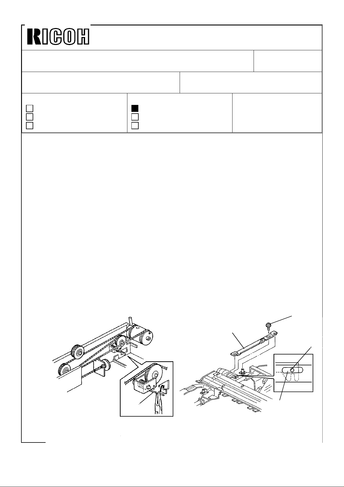
13. Unhook the front and rear wire tension springs [C] and remove the wires. Set the first
and second scanner fixing bracket [D] to the first and second scanners and set it
using M4 x 8 screw [E] with a washer.
NOTE: 1) This fixing bracket is a shipping retainer to be removed when installing the
machine.
2) Position the hole [F] of the scanner drive motor bracket to the center of the
long hole [G] of the fixing bracket.
[E]
[D]
[C]
[G]
[F]
Page 4
Technical Bulletin No. RTB-027
SUBJECT: Manual Correction DATE: May 31, ’91
PAGE: 2 of 2
Incorrect
15. Wrap the two wires side by side 3 times along the grooves of the scanner drive pulley.
NOTE: If the wires are properly wrapped, you will count seven wires on the scanner
drive pulley with the long wire outside of the scanner drive pulley.
25. Remove the front and second scanner positioning clamps.
35. Set the first and second scanner positioning clamps.
Correct
15. Wrap the two wires side by side 2 times along the grooves of the scanner drive pulley.
NOTE: If the wires are properly wrapped, you should see five wires on the scanner drive
pulley, with the long wire on the outside of the scanner drive pulley.
25. Remove the first and second scanner fixing bracket.
35. Set the first and second scanner fixing bracket.
Page 5

Technical Bulletin No. RTB-028
SUBJECT: Sorter /sorter stapler installation as a 20 bin, or 40 bin
system
PREPARED BY: I. Kakegawa
CHECKED BY:
CLASSIFICATION:
Action Required
Troubleshooting
Retrofit Information
This RTB clarifies installation of the sorter, sorter stapler, and connector units on the F20,
F21, and F22. Both 20bin and 40 bin systems are covered.
Because the F20, F21, and F22 copy at different speeds, the main PCB ROM on the old
sorter or sorter stapler must be replaced on some types of systems. Therefore, please
read this RTB carefully for F20/F21/F22 system installation.
1. TYPES OF SYSTEM
There are 8 types of F20/F21/F22 systems:
[Sorter System]
Revision of service manual
Information only
Other
FROM: Copier Technical Support Sec.
MODEL: F20
(Same RTB for F22--No.11 and
F21--No.17 are issued.)
DATE: July 15,’90
PAGE: 1 of 8
1) F20 or F21 + one sorter (20 bins) ....................No special action needed.
*2) F20 or F21 + two sorters (40 bins)....................See page 2 and 3.
3) F22 + one sorter (20 bins).................................No special action needed.
*4) F22 + two sorters (40 bins) ...............................See page 2 and 4.
[Sorter Stapler System]
1) F21 + one sorter stapler (20 bins).....................No special action needed.
*2) F21 + two sorter staplers (40 bins)....................See page 5 and 6.
*3) F22 + one sorter stapler (20 bins) .....................See page 5 and 7.
*4) F22 + two sorter staplers (40 bins)....................See page 5 and 8.
NOTE: Systems marked * need to have the ROM replaced if the old sorter or old sorter
stapler is used. Pay special attention to these systems.
Page 6

Technical Bulletin No. RTB-028
SUBJECT: Sorter /sorter stapler installation as a 20 bin, or 40 bin
system
DATE: July 15,’90
PAGE: 2 of 8
2. SORTER SYSTEM
2--1. Modification history for two sorters and connector unit
Model Code Sorter: 5937 -- Sorter: A462 -- Sorter Connector
Unit: 5946 --
Model Name
P/N for
the sorter
ROM
Ricoh CS2060 for F20
Infotec sorter 9060 for F20
Nashua D820 for
F20/21/22.
Savin FS65 for F20/21.
Pitney Bowes D820 for
F20/21
Ricoh CS 2065 for F21/F22
Infotec Sorter 9165 for
F21/22
Savin Sorter for F22
Sorter Connector unit, type A.
Type 1 P/N 59375603 No production No production
Modification (1)
No sorter ROM enclosed in
the accessary box.
One piece of ROM with P/N
59375613 "G" is enclosed.
Type 2
P/N 59375613
from no suffi to "F"
Modification (2) Modification (3)
P/N 59375613
from no suffix to "F"
Type 3 P/N 59375613 "G" P/N 59375613 "G"
Modification (4)
NOTE:
Modification (1) is to adapt the F20/F21 with a 40 bin system from type 2 ROM.
Modification (2) and (3) are to adapt the F22 with a 40 bin system from type 3 ROM.
Modification (4) is to adapt the F22 with a 40 bin system even if old sorters
(type 1, or 2) in stock are used.
As you can see from the above table, there are:
•Three types of sorters for model code 5937
•Two types of sorters for model code A462
•Two types of connector units.
Page 7

Technical Bulletin No. RTB-028
SUBJECT: Sorter /sorter stapler installation as a 20 bin, or 40 bin
system
DATE: July 15,’90
PAGE: 3 of 8
2--2. Necessary action by type of sorter system
[F20 or F21 + two sorters + connector unit (40 bins)]
With this type of system, the action required differs depending on the type of ROM on the
sorter main PCB and by type of the connector unit.
So, please check the part number of ROM and the serial number of the sorter and
connector unit. Then, you can know the type (old or new) of your sorter and connector
unit. For each type, please refer to page 2.
Sorter
[Cut-in serial number for modification (1)]
(From August, ’86 production onward.)
(See Modification (1) )
Old
(Type 1)
Sorter
Connector
Unit
5946--17 Ricoh USA
5946--27 Ricoh Europe
Nashua Europe
5946--27 Infotec 3441200001
Old
(Type 2)
New
(Type 3)
[Cut-in serial number for modification (4)
(From December, ’90 production onward)
Model S/N
Savin
Pitney Bowes
[A] [C]
[B] [D]
(Type 2 and 3)
21105xxxxx
2101200505
New
5937-11(Pitney Bowes) 6080001
5937-15 (Savin) 9460800025
5937-17 (Ricoh, USA) 1660800075
5937-25 (Nashua) 9260800002
5937-26 (Infotec) from first
5937-27 (Ricoh Europe) 1660800036
A462- all models from first
Model S/N
production
production
[A]: Old sorter (Type 1) + Old connector unit (Type 2).
The old ROM (P/N 59375603) on the first sorter main PCB should be replaced with
a new ROM. P/N 59375613, (no suffix or any suffix from A to G) is acceptable.
The ROM is not included, so please prepare one before installation.
[B]: Old sorter (Type 1) + New connector unit (Type 3).
The old ROM (P/N 59375603) on the first sorter main PCB should be replaced with
a new ROM (P/N 59375613G) enclosed in the carton box of the new connector
unit.
[C]: New sorter (Type 2 or 3) + Old connector unit (Type 2).
Since the sorter has a new ROM for 40 bins system, no action is required.
[D]: New sorter (Type 2 or 3) + New connector unit (Type 3).
No ROM replacement is required.
Page 8

Technical Bulletin No. RTB-028
SUBJECT: Sorter /sorter stapler installation as a 20 bin, or 40 bin
system
DATE: July 15,’90
PAGE: 4 of 8
[F22 + two sorters + connector unit (40 bins)]
With this type of system, the action required differs depending on the type of ROM on the
sorter main PCB and by type of the connector unit.
So, please check the part number of ROM and the serial number of the sorter and
connector unit. Then, you can know the type (old or new) of your sorter and connector
unit. For each type, please refer to page 2.
Sorter
(See Modification (2) and (3))
Old
(Type 1and 2)
Sorter
Connector
Unit
5946--17 Ricoh USA
5946--27 Ricoh Europe
5946--27 Infotec 3441200001
Old
(Type 2)
New
(Type 3)
[Cutrin serial number for modification (4)
(From December, ’90 production onward)
Model S/N
Savin
Nashua Canada
Nashua Europe
[A] [C]
[B] [D]
New
(Type 3)
21105xxxxx
2101200505
[Cut-in serial number for modification (2)
and (3)] (From February or March, ’91 production onward)
Model S/N
5937-11(Pitney Bowes) No production
5937-15 (Savin) 94105xxxxx
5937-17 (Ricoh, USA) No production
5937-25 (Nashua) 9210300859
5937-26 (Infotec) No production
5937-27 (Ricoh Europe) No production
A462-15 (Savin) 385106xxxx
A462-17 (Ricoh, USA) 2451020001
A462-26 (Infotec) 3860410001
A462-27 (Ricoh Europe) 2451020046
[A]: Old sorter (Type 1 or 2) + Old connector unit (Type 2).
The old ROM (P/N 59375603, or P/N 59375613 up to suffer "F") on the first sorter
main PCB should be replaced with a new ROM.(P/N 59375613G),
The new ROM is not included, so please prepare one before installation.
[B]: Old sorter (Type 1 or 2) + New connector unit (Type 3).
The old ROM (P/N 59375603, or P/N 59375613 up to suffix "F") on the first sorter
main PCB should be replaced with a new ROM (P/N 59375613G) enclosed in the
carton box of the new connector unit.
[C]: New sorter (Type 3) + Old connector unit (Type 2).
Since the sorter has a new ROM (P/N 59375613G), no action is required.
[D]: New sorter (Type 3) + New connector unit (Type 3).
No ROM replacement is required.
Page 9

Technical Bulletin No. RTB-028
SUBJECT: Sorter /sorter stapler installation as a 20 bin, or 40 bin
system
3. SORTER STAPLER SYSTEM
3--1. Modification history for sorter stapler and connector unit
Sorter Stapler: A469
Type 1
Type 2
Type 3
NOTE: • Modification (1) is to adapt the F21 with a 40 bin system from type 2 ROM.
ROM P/N 4695102 with
suffix form "B" to "E"
Modification (1)
ROM P/N A4695103 (No
suffix)
Modification (2)
ROM P/N A4695103 "A" or
"B"
Serter Stapler Connector
Unit: A310
No Production
Two pieces of ROM with
P/N A3105106A are
enclosed.
Modification (3)
ROM P/N A4695103A or B
DATE: July 15,’90
PAGE: 5 of 8
• Modification (2) is to adapt the F22 with either a 20 bin or a 40 bin system from
type 3 ROM.
• Accessory ROMs (P/N A3105106A) in the connector unit (type 2) are used
when the old sorter staplers (type 1) are installed on the F21 as a 40 bin
system.
(P/N A3105106A has the same program as P/N A4695103 with no suffix.)
• Modification (3) is to adapt the F22 with a 40 bin system even if old sorters
(type 1 and 2) are used.
As you can see from the above table, there are ;
•Three types of sorter staplers
•Two types of connector units
Page 10

Technical Bulletin No. RTB-028
SUBJECT: Sorter /sorter stapler installation as a 20 bin, or 40 bin
system
DATE: July 15,’90
PAGE: 6 of 8
3--2. Necessary action by type of sorter stapler system
[F21 + two sorter staplers + connector unit (40 bins)]
In this system, an action required is different by type of ROM on the sorter stapler main
PCB and by type of the connector unit.
So, please check the part number of ROM and the serial number of sorter stapler and
connector unit. Then, you can know the type (old or new) for your sorter stapler and
connector unit. For each type, please refer to page 5.
Sorter stapler
Old
(Type 1)
Old
Connector
Unit
A310--17 115V/60Hz 2670100001
A310--27 220, 240V/50Hz 2680100001
(Type 2)
New
(Type 3)
[Cut-in serial number for modification (3)
(From October, ’90 onwards)
Model S/N
[A] [C]
[B] [D]
(Type 2 and 3)
New
[Cut-in serial number for modification (1)]
(From June, ’90 production onward.)
Model S/N
A469-11 (Pitney Bowes) 0060001
A469-15 (Savin) 3120060001
A469-16 (Nashua
Canada)
A469-17 (Ricoh, USA) 2440060001
A469-25 (Nashua Europe) 1220070006
A469-26 (Infotec) 383090xxxx
A469-27 (Ricoh Europe) 2440060342
A469-55 (Savin) From the first
M/B Sorter Stapler No 20
issued on Aug- 31,’90)
1220060001
production
[A]: Old sorter stapler (Type 1) + Old connector unit (Type 2).
The old ROM (P/N A4695102B to E) on the sorter stapler main PCB should be
replaced with the ROMs enclosed in the sorter stapler connector unit (P/N
A3105106A).
[B]: Old sorter stapler (Type 1) + New connector unit (Type 3).
The old ROM (P/N A4695102B to E) on the sorter stapler main PCB should be
replaced with the ROMs enclosed in the sorter stapler connector unit (P/N
A4695103A or B).
[C]: New sorter stapler (Type 2 or 3) + Old connector unit (Type 2).
Since the sorter stapler main PCB already has a new ROM (P/N A4695103), it is
not necessary to replace it.
[D]: New sorter stapler (Type 2 and 3) + Old connector unit (Type 3).
Same as [C].
Page 11

Technical Bulletin No. RTB-028
SUBJECT: Sorter /sorter stapler installation as a 20 bin, or 40 bin
system
[F22 + one sorter stapler (20 bins)]
•See RTB F22 No 5.
•When an old sorter stapler (type 1 and 2) is installed on the F22, a new ROM (P/N
A4695103A or B) is required. Prepare a new ROM and replace the old ROM on the
sorter stapler main PCB (P/N A4695102B to E, or A4695103 with no suffix) with a
new ROM (P/N A4695103A or B, P/N A4695103A or B).
•Cut-in serial number for modification (2)
(From October, ’90 production anward.
Model Name V/Hz Code S/N
Pitney Bowes D962 115V/60 Hz A469-11 011xxxx
Savin 7640 S/F 115V/60 Hz A469-15 3120100001
Nashua SR 4965 115V/60 Hz A469-16 1220100001
Ricoh ST 20 115V/60 Hz A469-17 2440100001
Nashya SR 4965 220, 240V/50 Hz A469-25 1220100006
Infotec S/S 9165 220, 240V/50 Hz A469-26 3831100001
Ricoh ST 20 220, 240V/50 Hz A469-27 2440100001
Savin 9710 S/F 115V/60 Hz A469-55 2820100001
DATE: July 15,’90
PAGE: 7 of 8
From the above S/N, a new ROM (P/N A4695103A) has been used at the
factory.
Page 12

Technical Bulletin No. RTB-028
SUBJECT: Sorter /sorter stapler installation as a 20 bin, or 40 bin
system
[F22 + two sorter staplers + connector unit (40 bins)]
Sorter stapler
Connector
Unit
[Cut-in serial number for modification (3)]
Old
(Type 2)
New
(Type 3)
Old
(Type 1 and 2)
[A] [C]
[B] [D]
New
(Type 3)
Cut-in serial number for
modification (2):
See the table in page 7.
(From October,’90 production onward.)
Model S/N
A310--17 115V/60Hz 2670100001
A310--27 220, 240V/50Hz 2680100001
[A]: Old Sorter stapler (Type 1 and 2) + Old connector unit (Type 2).
Prepare two new ROMs (P/N A4695103A or B) and replace the old ROM on each
sorter stapler main PCB with a new one.
DATE: July 15,’90
PAGE: 8 of 8
[B]: Old sorter stapler (Type 1 and 2) + New connector unit (Type 3).
The old ROM on the sorter stapler main PCB should be replaced with the new
ROM (P/N A4695103A or B) enclosed in the new connector unit.
[C]: New sorter stapler (Type 3) + Old connector unit (Type 2).
Since the sorter stapler has a new ROM (P/N A4695103A or B), the old ROMs
(P/N A3105106A) in the old connector unit should not be used. Keep the original
new ROM on the sorter stapler main PCB.
(If it is replaced, paper jam in the sorter stapler may occur.)
[D]: New sorter stapler (Type 3) + New connector unit (Type 3).
Since the sorter stapler has a new ROM (P/N A4695103A or B), ROM replacement
is not necessary.
NOTE:
You can keep the two new accessory ROMs (P/M A4695103A) for these systems as
spare ROMs ;
•F22 + old sorter stapler (type 1 or 2) for 20 bins, or
•F22 + two old sorter staplers (type 1 or 2) + old connector unit.
 Loading...