

Ricoh A265, 220, 270, A267 Service Manual
Russian - C (A265/A267)
SERVICE MANUAL

ø
IMPORTANT SAFETY NOTICES
PREVENTION OF PHYSICAL INJURY
1. Before disassembling or assembling parts of the copier and peripherals,
make sure that the copier power cord is unplugged.
2. The wall outlet should be near the copier and easily accessible.
3. If any adjustment or operation check has to be made with exterior covers off
or open while the main switch is turned on, keep hands away from electrified
or mechanically driven components.
4. If a job has started before the copier completes the warm-up or initializing
period, keep hands away from the mechanical and electrical components
because the starts making copies as soon as the warm-up period is
completed.
5. The inside and the metal parts of the fusing unit become extremely hot while
the copier is operating. Be careful to avoid touching those components with
your bare hands.
HEALTH SAFETY CONDITIONS
Toner is non-toxic, but if you get it in your eyes by accident, it may cause
temporary eye discomfort. Try to remove with eye drops or flush with water as
first aid. If unsuccessful, get medical attention.
SAFETY AND ECOLOGICAL NOTES FOR DISPOSAL
1. Do not incinerate the toner cassettes. Toner dust may ignite suddenly when
exposed to an open flame.
2. Dispose of toner cassettes in accordance with local regulations. (This is a
non-toxic unit.)
3. Dispose of replaced parts in accordance with local regulations.
i

LASER SAFETY
The Center for Devices and Radiological Health (CDRH) prohibits the repair of
laser-based optical units in the field. The optical housing unit can only be repaired
in a factory or at a location with the requisite equipment. The laser subsystem is
replaceable in the field by a qualified Customer Engineer. The laser chassis is not
repairable in the field. Customer engineers are therefore directed to return all
chassis and laser subsystems to the factory or service depot when replacement of
the optical subsystem is required.
ø
WARNING
Use of controls, or adjustment, or performance of procedures other than
those specified in this manual may result in hazardous radiation exposure.
ø
WARNING FOR LASER UNIT
WARNING: Turn off the main switch before attempting any of the
procedures in the Laser Unit section. Laser beams can
seriously damage your eyes.
CAUTION MARKING:
laser-4.WMF
ii

TABLE OF CONTENTS
1. OVERALL MACHINE INFORMATION........................................1-1
1.1 SPECIFICATIONS.................................................................................... 1-1
1.2 MACHINE CONFIGURATION.................................................................. 1-5
1.2.1 SYSTEM COMPONENTS ............................................................... 1-5
1.2.2 INSTALLABLE OPTION TABLE...................................................... 1-7
Copier options...................................................................................... 1-7
Fax and printer options........................................................................ 1-7
Scanner option..................................................................................... 1-7
1.3 PAPER PATH........................................................................................... 1-8
1.4 MECHANICAL COMPONENT LAYOUT................................................... 1-9
1.5 ELECTRICAL COMPONENT DESCRIPTIONS...................................... 1-11
1.6 DRIVE LAYOUT ..................................................................................... 1-14
1.7 COPY PROCESS................................................................................... 1-15
1.7.1 OVERVIEW ................................................................................... 1-15
1.8 BOARD STRUCTURE............................................................................ 1-17
1.8.1 OVERVIEW ................................................................................... 1-17
1.8.2 DESCRIPTION .............................................................................. 1-18
2. DETAILED SECTION DESCRIPTIONS.......................................2-1
2.1 SCANNING............................................................................................... 2-1
2.1.1 OVERVIEW ..................................................................................... 2-1
2.1.2 SCANNER DRIVE ........................................................................... 2-2
2.1.3 ORIGINAL SIZE DETECTION IN PLATEN MODE.......................... 2-3
2.2 IMAGE PROCESSING ............................................................................. 2-5
2.2.1 OVERVIEW ..................................................................................... 2-5
2.2.2 SBU (SENSOR BOARD UNIT)........................................................ 2-6
2.2.3 AUTO IMAGE DENSITY.................................................................. 2-7
In the SBU............................................................................................ 2-7
In the IPU............................................................................................. 2-7
“Service Mode” Original Types............................................................ 2-7
2.2.4 IPU (IMAGE PROCESSING UNIT).................................................. 2-8
Overview.............................................................................................. 2-8
Image Processing Modes..................................................................... 2-9
Image Processing Path...................................................................... 2-11
SP Modes for Each Image Processing Step...................................... 2-12
Auto Shading...................................................................................... 2-18
White Line Erase Compensation........................................................ 2-18
Black Line Erase Compensation........................................................ 2-18
Scanner Gamma (γ Correction........................................................... 2-19
Main Scan Magnification/Reduction................................................... 2-20
Mirroring for ADF Mode...................................................................... 2-20
Filtering .............................................................................................. 2-21
ID Gamma (γ) Correction ................................................................... 2-25
Gradation Processing......................................................................... 2-25
i

Line width correction.......................................................................... 2-27
2.2.5 MEMORY CONTROLLER AND ENHANCED MEMORY
BOARD (EMB).............................................................................. 2-28
2.2.6 VIDEO CONTROL UNIT (VCU)..................................................... 2-29
Fine Character and Image (FCI)........................................................ 2-29
Printer Gamma Correction................................................................. 2-29
2.3 LASER EXPOSURE............................................................................... 2-30
2.3.1 OVERVIEW ................................................................................... 2-30
2.3.2 AUTO POWER CONTROL (APC) ................................................. 2-31
2.3.3 LD SAFETY SWITCH.................................................................... 2-32
2.4 PHOTOCONDUCTOR UNIT (PCU)........................................................ 2-33
2.4.1 OVERVIEW ................................................................................... 2-33
2.4.2 DRIVE............................................................................................ 2-34
2.4.3 NEW PCU DETECTION................................................................ 2-35
2.5 DRUM CHARGE..................................................................................... 2-36
2.5.1 OVERVIEW ................................................................................... 2-36
2.5.1 CHARGE ROLLER VOLTAGE CORRECTION............................. 2-37
Correction for Environmental Conditions............................................ 2-37
2.5.2 ID SENSOR PATTERN PRODUCTION TIMING........................... 2-38
2.5.3 DRUM CHARGE ROLLER CLEANING......................................... 2-39
2.6 DEVELOPMENT..................................................................................... 2-40
2.6.1 OVERVIEW ................................................................................... 2-40
2.6.2 DRIVE............................................................................................ 2-41
2.6.3 DEVELOPER MIXING................................................................... 2-42
2.6.4 DEVELOPMENT BIAS................................................................... 2-43
2.6.5 TONER SUPPLY........................................................................... 2-44
Toner bottle replenishment mechanism............................................. 2-44
Toner supply mechanism................................................................... 2-45
2.6.6 TONER DENSITY CONTROL....................................................... 2-46
Overview............................................................................................ 2-46
Toner density sensor initial setting..................................................... 2-48
Toner density measurement .............................................................. 2-48
Vsp/Vsg detection.............................................................................. 2-48
Toner supply reference voltage (Vref) determination......................... 2-48
Toner supply determination................................................................ 2-48
Toner Supply Motor On Time Determinations.................................... 2-49
2.6.7 TONER SUPPLY IN ABNORMAL SENSOR CONDITIONS.......... 2-50
ID sensor............................................................................................ 2-50
TD Sensor.......................................................................................... 2-50
2.6.8 TONER NEAR END/END DETECTION AND RECOVERY........... 2-50
Toner Near End Detection ................................................................. 2-50
Toner Near End Recovery.................................................................. 2-51
Toner End Detection.......................................................................... 2-51
Toner End Recovery.......................................................................... 2-51
2.7 DRUM CLEANING AND TONER RECYCLING...................................... 2-52
2.7.1 DRUM CLEANING......................................................................... 2-52
2.7.2 TONER RECYCLING .................................................................... 2-53
2.8 PAPER FEED......................................................................................... 2-54
2.8.1 OVERVIEW ................................................................................... 2-54
ii

2.8.2 PAPER FEED DRIVE MECHANISM ............................................. 2-55
2.8.3 PAPER FEED AND SEPARATION MECHANISM......................... 2-56
2.8.4 PAPER LIFT MECHANISM............................................................ 2-57
2.8.5 PAPER END DETECTION............................................................. 2-58
2.8.6 PAPER HEIGHT DETECTION....................................................... 2-59
2.8.7 FEED PRESSURE ADJUSTMENT FOR PAPER SIZE................. 2-60
Overview............................................................................................ 2-60
Paper Size Thresholds....................................................................... 2-60
Feed Pressure Adjustment................................................................. 2-61
Effect of the Amount of Remaining Paper.......................................... 2-61
2.8.8 PAPER SIZE DETECTION............................................................ 2-63
2.8.9 SPECIAL PAPER SETTING.......................................................... 2-64
2.8.10 SIDE AND END FENCES............................................................ 2-65
Side Fences....................................................................................... 2-65
End Fence.......................................................................................... 2-65
2.8.11 PAPER REGISTRATION............................................................. 2-66
2.9 IMAGE TRANSFER AND PAPER SEPARATION.................................. 2-67
2.9.1 OVERVIEW ................................................................................... 2-67
2.9.2 IMAGE TRANSFER CURRENT TIMING....................................... 2-68
2.9.3 TRANSFER ROLLER CLEANING................................................. 2-69
2.9.4 PAPER SEPARATION MECHANISM............................................ 2-69
2.10 IMAGE FUSING AND PAPER EXIT..................................................... 2-70
2.10.1 OVERVIEW ................................................................................. 2-70
2.10.2 FUSING DRIVE AND RELEASE MECHANISM........................... 2-71
2.10.3 FUSING ENTRANCE GUIDE SHIFT MECHANISM.................... 2-72
2.10.4 PRESSURE ROLLER.................................................................. 2-73
2.10.5 CLEANING MECHANISM............................................................ 2-73
2.10.6 FUSING TEMPERATURE CONTROL......................................... 2-74
Temperature Control.......................................................................... 2-74
Fusing Lamp Control.......................................................................... 2-75
2.10.7 OVERHEAT PROTECTION......................................................... 2-76
2.10.8 PAPER EXIT................................................................................ 2-76
2.11 ENERGY SAVER MODES ................................................................... 2-77
2.11.1 OVERVIEW ................................................................................. 2-77
2.11.2 ENERGY SAVER MODE............................................................. 2-78
Entering the energy saver mode........................................................ 2-78
What happens in energy saver mode................................................. 2-78
Return to stand-by mode.................................................................... 2-78
2.11.3 LOW POWER MODE .................................................................. 2-79
Entering the low power mode............................................................. 2-79
What happens in low power mode..................................................... 2-79
Return to stand-by mode.................................................................... 2-79
2.11.4 AUTO OFF MODE....................................................................... 2-80
Entering auto off mode....................................................................... 2-80
What happens in auto off mode ......................................................... 2-80
Returning to stand-by mode............................................................... 2-80
Disabling auto off mode ..................................................................... 2-80
2.11.5 NIGHT MODE.............................................................................. 2-81
Entering night stand-by and night modes........................................... 2-81
iii

What happens in night stand-by and night modes............................. 2-81
Returning to stand-by mode............................................................... 2-82
3. INSTALLATION PROCEDURE...................................................3-1
3.1 INSTALLATION REQUIREMENTS .......................................................... 3-1
3.1.1 ENVIRONMENT .............................................................................. 3-1
3.1.2 MACHINE LEVEL............................................................................ 3-1
3.1.3 MINIMUM SPACE REQUIREMENTS.............................................. 3-2
3.1.4 POWER REQUIREMENTS.............................................................. 3-3
3.2 COPIER INSTALLATION.......................................................................... 3-4
3.2.1 POWER SOCKETS FOR PERIPHERALS....................................... 3-4
3.2.2 INSTALLATION FLOW CHART....................................................... 3-5
3.2.3 ACCESSORY CHECK..................................................................... 3-6
3.2.4 INSTALLATION PROCEDURE........................................................ 3-7
3.3 PAPER TRAY UNIT INSTALLATION..................................................... 3-11
3.3.1 ACCESSORY CHECK................................................................... 3-11
3.4 LCT INSTALLATION .............................................................................. 3-14
3.4.1 ACCESSORY CHECK................................................................... 3-14
3.5 AUTO REVERSE DOCUMENT FEEDER INSTALLATION.................... 3-17
3.5.1 ACCESSORY CHECK................................................................... 3-17
3.5.2 INSTALLATION PROCEDURE...................................................... 3-17
3.6 INTERCHANGE UNIT INSTALLATION.................................................. 3-20
3.6.1 COMPONENT CHECK.................................................................. 3-20
3.6.2 INSTALLATION PROCEDURE...................................................... 3-21
3.7 1-BIN TRAY UNIT INSTALLATION ........................................................ 3-23
3.7.1 COMPONENT CHECK.................................................................. 3-23
3.7.2 INSTALLATION PROCEDURE...................................................... 3-23
3.8 SHIFT TRAY........................................................................................... 3-26
3.8.1 COMPONENT CHECK.................................................................. 3-26
3.8.2 INSTALLATION PROCEDURE...................................................... 3-26
3.9 BY-PASS FEED UNIT INSTALLATION.................................................. 3-28
3.9.1 COMPONENTS CHECK................................................................ 3-28
3.9.2 INSTALLATION PROCEDURE...................................................... 3-28
3.10 DUPLEX UNIT INSTALLATION............................................................ 3-30
3.10.1 ACCESSORY CHECK................................................................. 3-30
3.10.2 INSTALLATION PROCEDURE.................................................... 3-31
3.11 BRIDGE UNIT INSTALLATION............................................................ 3-33
3.11.1 ACCESSORY CHECK................................................................. 3-33
3.11.2 INSTALLATION PROCEDURE.................................................... 3-33
3.12 1,000-SHEET FINISHER INSTALLATION............................................ 3-35
3.13 COPIER FEATURE EXPANDER INSTALLATION............................... 3-38
3.14 PLATEN COVER INSTALLATION........................................................ 3-39
3.15 KEY COUNTER INSTALLATION ......................................................... 3-40
3.16 ANTI-CONDENSATION HEATER........................................................ 3-42
3.17 TRAY HEATER..................................................................................... 3-43
3.18 TRAY HEATER (OPTIONAL PAPER TRAY UNIT).............................. 3-45
3.19 TRAY HEATER (OPTIONAL LCT) ....................................................... 3-48
iv

4. SERVICE TABLES......................................................................4-1
4.1 GENERAL CAUTION................................................................................ 4-1
4.1.1 PCU (PHOTOCONDUCTOR UNIT)................................................. 4-1
4.1.2 TRANSFER ROLLER UNIT............................................................. 4-1
4.1.3 SCANNER UNIT.............................................................................. 4-1
4.1.4 LASER UNIT.................................................................................... 4-2
4.1.5 FUSING UNIT.................................................................................. 4-2
4.1.6 PAPER FEED.................................................................................. 4-2
4.1.7 OTHERS.......................................................................................... 4-2
4.2 SERVICE PROGRAM MODE................................................................... 4-3
4.2.1 SERVICE PROGRAM MODE OPERATION.................................... 4-3
Service Program Access Procedure.................................................... 4-3
Accessing Copy Mode from within an SP Mode .................................. 4-4
How to Select the Program Number..................................................... 4-4
To input a value or setting for an SP mode.......................................... 4-4
4.2.2 SERVICE PROGRAM MODE TABLES........................................... 4-5
4.2.3 TEST PATTERN PRINTING (SP4-417 AND SP5-902)................. 4-60
4.2.4 INPUT CHECK (SP5-803)............................................................. 4-61
Input Check Table.............................................................................. 4-61
4.2.5 OUTPUT CHECK (SP5-804)......................................................... 4-66
Output Check Table........................................................................... 4-66
4.2.6 COPY JAM HISTORY DISPLAY (SP7-903).................................. 4-68
4.2.7 SMC DATA LISTS (SP5-992)........................................................ 4-69
4.2.8 ORIGINAL JAM HISTORY DISPLAY (SP7-905)........................... 4-70
4.2.9 MEMORY ALL CLEAR (SP5-801)................................................. 4-71
Using a Flash Memory Card............................................................... 4-71
Without Using a Flash Memory Card................................................. 4-71
4.2.10 PROGRAM UPLOAD/DOWNLOAD............................................. 4-72
Program Download (SP5-827)........................................................... 4-72
Program Upload (SP5-826)................................................................ 4-73
4.2.11 NVRAM DATA DOWNLOAD....................................................... 4-74
NVRAM Data Download (SP5-825)................................................... 4-74
NVRAM Data Upload (SP5-824)........................................................ 4-75
4.2.12 APS AND PLATEN/DF COVER SENSOR OUTPUT DISPLAY
(SP4-301)...................................................................................... 4-76
4.2.13 DF APS SENSOR OUTPUT DISPLAY (SP6-901)....................... 4-77
4.2.14 NIP BAND WIDTH MEASUREMENT .......................................... 4-78
4.2.15 DISPLAY LANGUAGE (SP5-808)................................................ 4-79
4.2.16 SERIAL NUMBER INPUT (SP5-811)........................................... 4-79
4.2.17 ID SENSOR ERROR ANALYSIS (SP2-221)................................4-80
4.3 USER TOOLS......................................................................................... 4-81
4.3.1 HOW TO ENTER AND EXIT USER TOOLS..................................4-81
4.3.2 USER TOOLS TABLE ................................................................... 4-81
System Setting Table......................................................................... 4-81
Copy Setting Table............................................................................. 4-82
4.4 LEDS...................................................................................................... 4-83
BICU .................................................................................................. 4-83
IOB..................................................................................................... 4-83
v

4.5 SPECIAL TOOLS AND LUBRICANTS ................................................... 4-83
4.5.1 SPECIAL TOOLS........................................................................... 4-83
4.5.2 LUBRICANTS................................................................................ 4-83
5. PREVENTIVE MAINTENANCE SCHEDULE...............................5-1
5.1 PM TABLE................................................................................................ 5-1
6. REPLACEMENT AND ADJUSTMENT ........................................ 6-1
6.1 SCANNER UNIT....................................................................................... 6-1
6.1.1 EXPOSURE GLASS........................................................................ 6-1
6.1.2 SCANNER EXTERIOR/OPERATION PANEL................................. 6-2
6.1.3 LENS BLOCK ASSEMBLY.............................................................. 6-3
6.1.4 ORIGINAL SIZE SENSORS/LAMP STABILIZER............................ 6-4
6.1.5 EXPOSURE LAMP.......................................................................... 6-5
6.1.6 SCANNER MOTOR......................................................................... 6-6
6.1.7 SCANNER WIRES........................................................................... 6-7
6.2 LASER UNIT........................................................................................... 6-10
6.2.1 CAUTION DECAL LOCATIONS.................................................... 6-10
6.2.2 LASER UNIT.................................................................................. 6-11
6.2.3 POLYGON MIRROR MOTOR....................................................... 6-12
6.2.4 LD UNIT......................................................................................... 6-12
6.2.5 LASER SYNCHRONIZATION DETECTOR................................... 6-13
6.3 PHOTOCONDUCTOR UNIT (PCU)........................................................ 6-14
6.3.1 PCU............................................................................................... 6-14
6.4 TRANSFER UNIT................................................................................... 6-15
6.4.1 TRANSFER ROLLER UNIT........................................................... 6-15
6.4.2 IMAGE DENSITY SENSOR........................................................... 6-16
6.5 FUSING/EXIT......................................................................................... 6-17
6.5.1 FUSING UNIT................................................................................ 6-17
6.5.2 THERMISTOR............................................................................... 6-17
6.5.3 THERMOFUSE.............................................................................. 6-18
6.5.4 HOT ROLLER AND FUSING LAMP.............................................. 6-19
6.5.5 PRESSURE ROLLER/CLEANING ROLLER................................. 6-20
6.5.6 PAPER EXIT SENSOR/PAPER OVERFLOW SENSOR............... 6-21
6.6 PAPER FEED......................................................................................... 6-22
6.6.1 FEED ROLLERS............................................................................ 6-22
6.6.2 PAPER END SENSOR.................................................................. 6-23
6.6.3 PAPER TRAY LIFT MOTORS....................................................... 6-24
6.6.4 REGISTRATION CLUTCH............................................................. 6-25
6.6.5 PAPER FEED CLUTCHES............................................................ 6-26
Lower Paper Feed Clutch .................................................................. 6-26
Upper Paper Feed Clutch. ................................................................. 6-26
6.6.6 RELAY CLUTCHES....................................................................... 6-27
6.6.7 PAPER SIZE DETECTOR/SPECIAL PAPER SENSOR................ 6-28
6.6.8 REGISTRATION SENSOR............................................................ 6-29
6.6.9 RELAY SENSORS......................................................................... 6-30
Upper Relay Sensor........................................................................... 6-30
Lower Relay Sensor........................................................................... 6-30
6.7 PCBS AND OTHER ITEMS.................................................................... 6-31
vi

6.7.1 BICU BOARD................................................................................. 6-31
6.7.2 I/O BOARD.................................................................................... 6-32
6.7.3 POWER PACK............................................................................... 6-32
6.7.4 MAIN MOTOR................................................................................ 6-33
6.7.5 PSU ............................................................................................... 6-34
6.8 COPY ADJUSTMENTS: PRINTING/SCANNING................................... 6-35
6.8.1 PRINTING...................................................................................... 6-35
Registration - Leading Edge/Side-to-Side.......................................... 6-35
Blank Margin...................................................................................... 6-36
Main Scan Magnification.................................................................... 6-36
Parallelogram Image Adjustment....................................................... 6-37
6.8.2 SCANNING.................................................................................... 6-38
Registration: Platen Mode.................................................................. 6-38
Magnification...................................................................................... 6-38
Standard White Density Adjustment................................................... 6-39
6.8.3 ADF IMAGE ADJUSTMENT.......................................................... 6-40
Registration........................................................................................ 6-40
7. TROUBLESHOOTING.................................................................7-1
7.1 SERVICE CALL CONDITIONS................................................................. 7-1
7.1.1 SUMMARY....................................................................................... 7-1
7.1.2 SC CODE DESCRIPTIONS............................................................. 7-2
SC194: IPU White Level Detection Error ............................................. 7-4
SC546: Unstable fusing temperature................................................... 7-9
SC620: Communication error between IOB and ADF........................ 7-10
SC760: ADF gate abnormal............................................................... 7-14
SC900: Electrical total counter error .................................................. 7-14
SC901: Mechanical Total Counter..................................................... 7-14
SC921: EMB (Copier feature expander) hardware error.................... 7-15
SC980: Program loading error ........................................................... 7-15
SC990: Communication error between BICU and IOB....................... 7-15
SC999: Program version error ........................................................... 7-15
7.2 PAPER FEED TROUBLESHOOTING.................................................... 7-16
7.3 SKEWED IMAGE.................................................................................... 7-17
7.4 TONER DENSITY................................................................................... 7-18
7.4.1 ADJUST THE TONER DENSITY CONTROL................................ 7-18
If the toner density is too low.............................................................. 7-18
If the toner density is too high............................................................ 7-18
7.4.2 DIRTY BACKGROUND ................................................................. 7-18
7.5 ELECTRICAL COMPONENT DEFECTS................................................ 7-19
7.5.1 SENSORS..................................................................................... 7-19
7.5.2 SWITCHES.................................................................................... 7-21
7.6 BLOWN FUSE CONDITIONS................................................................. 7-22
vii

OPTIONS
ADF (A858)
1. OVERALL MACH INE INFORMATION..................................A858-1
1.1 SPECIFICATIONS..............................................................................A858-1
1.2 MECHANICAL COMPONENT LAYOUT.............................................A858-2
1.3 ELECTRICAL COMPONENT LAYOUT..............................................A858-3
1.4 ELECTRICAL COMPONENT DESCRIPTION....................................A858-4
1.5 DRIVE LAYOUT .................................................................................A858-5
2. DETAILED SECTION DESCRIPTIONS................................. A858-6
2.1 ORIGINAL SIZE DETECTION............................................................A858-6
1.2 PICK-UP AND SEPARATION.............................................................A858-9
1.3 ORIGINAL TRANSPORT AND EXIT................................................A858-10
1.3.1 SINGLE-SIDED ORIGINALS...................................................A858-10
1.3.2 DOUBLE-SIDED ORIGINALS..................................................A858-11
1.3.3 ORIGINAL TRAILING EDGE SENSOR...................................A858-12
1.4 STAMP .............................................................................................A858-13
1.5 TIMING CHARTS .............................................................................A858-14
1.5.1 LT SIDEWAYS (SINGLE-SIDED ORIGINAL MODE) ..............A858-14
1.5.2 LT SIDEWAYS STAMP MODE
(SINGLE-SIDED ORIGINAL MODE)...................................A858-15
1.5.3 LT SIDEWAYS (DOUBLE-SIDED ORIGINAL MODE).............A858-16
1.5.4 LT SIDEWAYS STAMP MODE
(DOUBLE-SIDED ORIGINAL MODE) .................................A858-17
1.6 CONDITION OF JAM DETECTION..................................................A858-18
1.7 OVERALL ELECTRICAL CIRCUIT...................................................A858-19
3. REPLACEMENT A ND ADJUSTMENT................................A858-20
3.1 DF EXIT TABLE AND COVER .........................................................A858-20
3.2 ORIGINAL FEED UNIT.....................................................................A858-21
3.3 LEFT COVER...................................................................................A858-22
3.4 PICK-UP ROLLER............................................................................A858-23
3.5 FEED BELT......................................................................................A858-24
3.6 SEPARATION ROLLER...................................................................A858-25
3.7 ORIGINAL SET/ORIGINAL REVERSE SENSOR ............................A858-26
3.8 ORIGINAL LENGTH, WIDTHSENSOR BOARD AND
TRAILING EDGE SENSOR..............................................................A858-27
3.9 DF FEED CLUTCH/DF PICK-UP SOLENOID/ TRANSPORT/
DF FEED MOTORS ......................................................................... A858-28
DF Feed Clutch............................................................................A858-28
Pick-up Solenoid..........................................................................A858-28
Transport Motor............................................................................A858-28
DF Feed Motor.............................................................................A858-28
3.10 REGISTRATION SENSOR.............................................................A858-29
3.11 STAMP SOLENOID AND ORIGINAL EXIT SENSOR....................A858-30
viii

PAPER TRAY UNIT (A860)
1. OVERALL MACH INE INFORMATION..................................A860-1
1.1 SPECIFICATIONS..............................................................................A860-1
1.2 MECHANICAL COMPONENT LAYOUT.............................................A860-2
1.3 ELECTRICAL COMPONENT LAYOUT..............................................A860-3
1.4 ELECTRICAL COMPONENT DESCRIPTION....................................A860-4
1.5 DRIVE LAYOUT .................................................................................A860-5
2. DETAILED DESCRIPTIONS .................................................A860-6
2.1 PAPER FEED AND SEPARATION MECHANISM..............................A860-6
2.2 PAPER LIFT MECHANISM................................................................A860-7
2.3 PAPER END DETECTION.................................................................A860-9
2.4 PAPER HEIGHT DETECTION.........................................................A860-10
1.5 PAPER SIZE DETECTION...............................................................A860-12
1.6 SIDE AND END FENCES.................................................................A860-13
Side Fences.................................................................................A860-13
End Fence....................................................................................A860-13
3. REPLACEMENT AND ADJUSTMENT................................ A860-14
3.1 FEED ROLLER REPLACEMENT.....................................................A860-14
3.2 TRAY MAIN BOARD REPLACEMENT.............................................A860-15
3.3 TRAY MOTOR REPLACEMENT......................................................A860-15
3.4 RELAY CLUTCH REPLACEMENT...................................................A860-16
3.5 UPPER PAPER FEED CLUTCH REPLACEMENT ..........................A860-17
3.6 LOWER PAPER FEED CLUTCH REPLACEMENT..........................A860-18
3.7 LIFT MOTOR REPLACEMENT........................................................A860-19
3.8 PAPER END SENSOR REPLACEMENT.........................................A860-20
3.9 VERTICAL TRANSPORT SENSOR REPLACEMENT.....................A860-20
3.10 PAPER SIZE SWITCH REPLACEMENT........................................A860-21
LCT (A862)
1. OVERALL MACH INE INFORMATION..................................A862-1
1.1 SPECIFICATIONS..............................................................................A862-1
1.2 MECHANICAL COMPONENT LAYOUT.............................................A862-2
1.3 ELECTRICAL COMPONENT LAYOUT..............................................A862-3
1.4 ELECTRICAL COMPONENT DESCRIPTIONS..................................A862-4
2. DETAILED SECTION DESCRIPTIONS................................. A862-5
2.1 PAPER FEED.....................................................................................A862-5
2.2 REVERSE ROLLER AND PICK-UP ROLLER RELEASE...................A862-6
2.3 TRAY LIFT..........................................................................................A862-7
2.4 NEAR END/END DETECTION...........................................................A862-8
ix

2.5 RIGHT TRAY SIDE FENCE................................................................A862-9
2.6 LEFT TRAY REAR FENCE................................................................A862-9
2.7 RIGHT TRAY PAPER END DETECTION.........................................A862-10
3. REPLACEMENT A ND ADJUSTMENT................................A862-11
3.1 DETACHING THE TRAY FROM THE MAINFRAME........................A862-11
Rear Fence HP Sensor................................................................ a862-11
3.3 CHANGING THE TRAY PAPER SIZE..............................................A862-12
3.4 LEFT TRAY PAPER END SENSOR.................................................A862-12
3.5 TRAY LIFT MOTOR..........................................................................A862-13
3.6 TRAY MOTOR..................................................................................A862-14
3.7 PAPER FEED CLUTCH AND RELAY CLUTCH............................... A862-15
3.8 PAPER FEED UNIT..........................................................................A862-16
3.9 UPPER LIMIT, RIGHT TRAY PAPER END, AND
RELAY SENSORS...........................................................................A862-17
3.10 REAR FENCE MOTOR..................................................................A862-18
3.11 PICK-UP/PAPER FEED/REVERSE ROLLERS..............................A862-19
BY-PASS UNIT (A899)
1 OVERALL MACHINE INFORMATION...................................A899-1
1.1 SPECIFICATIONS..............................................................................A899-1
1.2 MECHANICAL COMPONENT LAYOUT.............................................A899-1
1.3 ELECTRICAL COMPONENT LAYOUT..............................................A899-2
1.4 ELECTRICAL COMPONENT DESCRIPTION....................................A899-2
2 DETAILED DESCRIPTIONs...................................................... a899-3
2.1 BASIC OPERATION...........................................................................A899-3
2.2 PAPER SIZE DETECTION.................................................................A899-4
3 REPLACEMENT AND ADJUSTMENT....................................... a899-5
3.1 PAPER FEED ROLLER/FRICTION PAD/PAPER END SENSOR......A899-5
3.2 PAPER SIZE SENSOR BOARD.........................................................A899-6
3.3 PAPER FEED CLUTCH......................................................................A899-7
x

INTERCHANGE UNIT (B300)
1. OVERALL MACH INE INFORMATION..................................B300-1
1.1 SPECIFICATIONS..............................................................................B300-1
1.2 MECHANICAL COMPONENT LAYOUT.............................................B300-2
1.3 DRIVE LAYOUT .................................................................................B300-3
2. DETAILED DESCRIPTION....................................................B300-4
2.1 JUNCTION GATE MECHANISM........................................................B300-4
To the Exit Tray or Bridge Unit (for the Upper Tray on top of
the Bridge Unit, or the Finisher).....................................................B300-4
To the 1-bin Tray............................................................................B300-4
To the Duplex Unit ......................................................................... B300-4
3. REPLACEMENT AND ADJUSTMENT..................................B300-5
3.1 EXIT SENSOR REPLACEMENT........................................................B300-5
DUPLEX (A896)
1. OVERALL MACH INE INFORMATION..................................A896-1
1.1 SPECIFICATIONS..............................................................................A896-1
1.2 MECHANICAL COMPONENT LAYOUT.............................................A896-2
1.3 ELECTRICAL COMPONENT LAYOUT..............................................A896-3
1.4 ELECTRICAL COMPONENT DESCRIPTION....................................A896-4
1.5 DRIVE LAYOUT .................................................................................A896-5
2. DETAILED DESCRIPTIONS .................................................A896-6
2.1 BASIC OPERATION...........................................................................A896-6
Larger than A4 lengthwise/LT Lengthwise.....................................A896-6
Up to A4 Lengthwise/LT lengthwise...............................................A896-7
2.2 FEED IN AND EXIT MECHANISM.....................................................A896-8
When Paper is Fed Into Duplex Unit:.............................................A896-8
Inversion and Exit:..........................................................................A896-8
3. REPLACEMENT A ND ADJUSTMENT..................................A896-9
3.1 COVER REMOVAL ............................................................................A896-9
3.2 ENTRANCE SENSOR REPLACEMENT.......................................... A896-10
3.3 EXIT SENSOR REPLACEMENT......................................................A896-11
xi

1 BIN TRAY UNIT (A898)
1. OVERALL INFORMATION.................................................... A898-1
1.1 SPECIFICATIONS..............................................................................A898-1
1.2 MECHANICAL COMPONENT LAYOUT.............................................A898-2
1.3 ELECTRICAL COMPONENT LAYOUT..............................................A898-3
1.4 ELECTRICAL COMPONENT DESCRIPTION....................................A898-3
2. DETAILED SECTION DESCRIPTIONS................................. A898-4
2.1 BASIC OPERATION...........................................................................A898-4
3. REPLACEMENT AND ADJUSTMENT..................................A898-5
3.1 PAPER SENSOR REMOVAL.............................................................A898-5
BRIDGE UNIT (A897)
1. OVERALL MACH INE INFORMATION..................................A897-1
1.1 SPECIFICATIONS..............................................................................A897-1
1.2 MECHANICAL COMPONENT LAYOUT.............................................A897-2
1.3 ELECTRICAL COMPONENT LAYOUT..............................................A897-3
1.4 ELECTRICAL COMPONENT DESCRIPTION....................................A897-4
1.5 DRIVE LAYOUT .................................................................................A897-5
2. DETAILED DESCRIPTION....................................................A897-6
2.1 JUNCTION GATE MECHANISM........................................................A897-6
3. REPLACEMENT AND ADJUSTMENT..................................A897-7
3.1 BRIDGE UNIT DRIVE MOTOR REPLACEMENT...............................A897-7
3.2 TRAY EXIT SENSOR REPLACEMENT .............................................A897-8
3.3 RELAY SENSOR REPLACEMENT....................................................A897-8
SHIFT TRAY UNIT (B313)
1 OVERALL MACHINE INFORMATION...................................B313-1
1.1 SPECIFICATIONS..............................................................................B313-1
1.2 COMPONENT LAYOUT.....................................................................B313-2
2. DETAILED SECTION DESCRIPTIONS................................. B313-3
2.1 BASIC OPERATION...........................................................................B313-3
2.2 PRIMARY MECHANISMS..................................................................B313-4
2.2.1 TRAY SHIFT..............................................................................B313-4
2.2.2 HALF TURN DETECTION......................................................... B313-5
xii

3. REPLACEMENT AND ADJUSTMENT..................................B313-6
3.1 TRAY COVER REPLACEMENT.........................................................B313-6
3.1.1 TRAY COVER REMOVAL.........................................................B313-6
3.1.2 TRAY COVER ATTACHMENT..................................................B313-6
3.2 TRAY MOTOR AND HALF TURN SENSOR REPLACEMENT ..........B313-7
3.2.1 REPLACING THE TRAY MOTOR.............................................B313-7
3.2.2 REPLACING THE HALF TURN SENSOR:................................B313-7
FINISHER (A681)
1. OVERALL MACH INE INFORMATION..................................A681-1
1.1 SPECIFICATIONS..............................................................................A681-1
1.2 MECHANICAL COMPONENT LAYOUT.............................................A681-2
1.3 ELECTRICAL COMPONENT LAYOUT..............................................A681-3
1.4 ELECTRICAL COMPONENT DESCRIPTIONS..................................A681-4
1.5 DRIVE LAYOUT .................................................................................A681-6
2. DETAILED DESCRIPTIONS .................................................A681-7
2.1 JUNCTION GATE MECHANISM........................................................A681-7
Staple Mode...................................................................................A681-7
No staple Mode..............................................................................A681-7
2.2 JOGGER UNIT PAPER POSITIONING MECHANISM.......................A681-8
2.3 EXIT GUIDE PLATE OPEN/CLOSE MECHANISM............................A681-9
2.4 STAPLER .........................................................................................A681-10
2.5 FEED OUT MECHANISM.................................................................A681-11
2.6 SHIFT TRAY UP/DOWN MECHANISM............................................A681-12
2.7 SHIFT TRAY SIDE-TO-SIDE MECHANISM.....................................A681-13
2.8 JAM CONDITIONS...........................................................................A681-14
2.9 TIMING CHARTS .............................................................................A681-15
2.9.1 NO STAPLE MODE (A4 SIDEWAYS, 3 SHEETS/2SETS)......A681-15
2.9.2 STAPLE MODE (A4 SIDEWAYS, 2 SHEETS/2 SETS)...........A681-16
3. SERVICE TABLE................................................................A681-17
3.1 DIP SWITCH TABLE........................................................................A681-17
3.2 TEST POINTS..................................................................................A681-17
3.3 FUSES.............................................................................................. A681-17
4. REPLACEMENT AND ADJUSTMENT................................ A681-18
4.1 COVER REMOVAL ..........................................................................A681-18
Front Door....................................................................................A681-18
Front Cover..................................................................................A681-18
Rear Cover...................................................................................A681-18
Upper Cover.................................................................................A681-18
Lower Left Cover..........................................................................A681-19
Front Shift Tray Cover..................................................................A681-19
Rear Shift Tray Cover ..................................................................A681-19
xiii

Shift Tray......................................................................................A681-19
4.2 ENTRANCE SENSOR REPLACEMENT.......................................... A681-20
4.3 EXIT SENSOR REPLACEMENT......................................................A681-21
4.4 STACK HEIGHT SENSOR REPLACEMENT...................................A681-22
4.5 POSITIONING ROLLER REPLACEMENT.......................................A681-23
4.6 STAPLER REPLACEMENT..............................................................A681-24
xiv

20 September 1999 SPECIFICATIONS
1. OVERALL MACHINE INFORMATION
1.1 SPECIFICATIONS
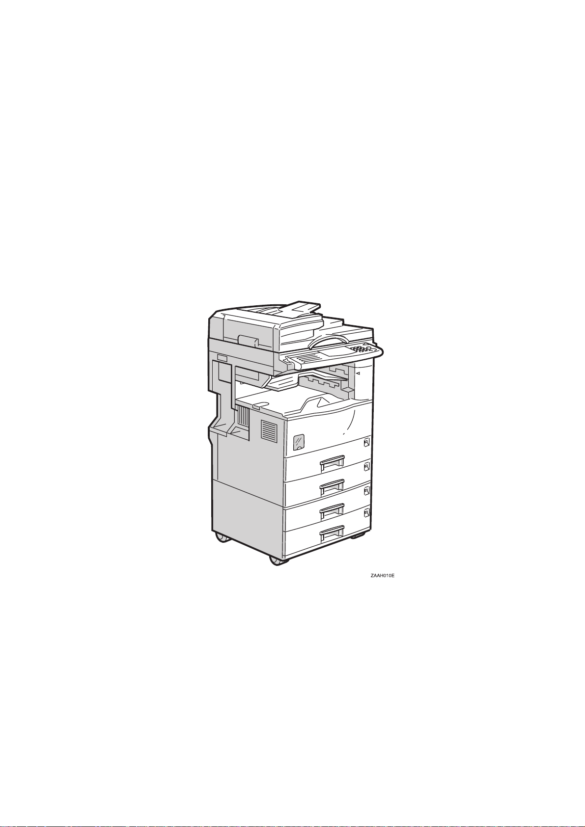
Configuration: Desktop
Copy Process: Dry electrostatic transfer system
Originals: Sheet/Book
Original Size: Maximum A3/11" x 17"
Copy Paper Size: Maximum
A3/11" x 17"
Minimum
A5/8
Custom sizes
2nd paper tray
Width: 100 ~ 297 mm (3.9" ~ 11.5")
Length: 148 ~ 432 mm (5.8" ~ 17.0")
By-pass tray (Option):
Width: 90 ~ 305 mm (3.5" ~ 12.0")
Length: 148 ~ 1,260 mm (5.8" ~ 49.6")
Copy Paper Weight: Paper Tray:
60 ~ 105 g/m2, 16 ~ 28 lb (1st paper tray)
60 ~ 157 g/m2, 16 ~ 43 lb (2nd paper tray)
By-pass (Option):
60 ~ 157 g/m2, 16 ~ 42 lb
1/2
" x 5
" lengthwise
1/2
Overall
Information
Reproduction Ratios: 5 Enlargement and 7 Reduction
A4/A3 Version LT/DLT Version
400%
200%
Enlargement
Full Size 100% 100%
Reduction
141%
122%
115%
93%
87%
82%
71%
65%
50%
25%
400%
200%
155%
129%
121%
93%
85%
78%
73%
65%
50%
25%
1-1

SPECIFICATIONS 20 September 1999
Zoom: 25% to 400% in 1% steps (Platen mode)
50% to 200% in 1% steps (ADF mode)
Power Source: 120 V, 60 Hz:
More than 12 A (for North America)
220 ~ 240 V, 50/60 Hz
More than 6 A (for Europe /Asia)
110 V, 50/60 Hz
More than 13 A (for Taiwan)
Power Consumption:
Mainframe Only Full System
120 V 220 ~ 240 V 120 V 220 ~ 240 V
Maximum
Copying
Warm-up
Stand-by
Low Power Level 1 Approx. 80 Wh Approx. 85 Wh Approx. 80 Wh Approx. 85 Wh
Low Power Level 2 Approx. 50 Wh Approx. 50 Wh Approx. 50 Wh Approx. 50 Wh
Auto Off 10 W -- 10 W --
Less than
1.44 kW
Approx.
500 Wh
Approx.
1.0 kW
Approx.
120 Wh
Less than
1.44 kW
Approx.
500 Wh
Approx.
1.0 kW
Approx.
120 Wh
Less than
1.44 kW
Approx.
500 Wh
Approx.
1.0 kW
Approx.
130 Wh
Less than
1.44 kW
Approx.
500 Wh
Approx.
1.0 kW
Approx.
130 Wh
NOTE:
1) Full system: Mainframe + ADF + 1-bin Sorter + Paper Tray Unit +
Duplex Unit + Bridge Unit + Finisher
2) Without the optional heaters, fax unit, and pri nter contr ol ler
Noise Emission (Sound Power Level):
Stand-by (Mainframe only): US/Asia Model: 40 dB(A)
Europe Model: 40 dB(A)
Operating (Mainframe only): US/Asia Model: 64 dB(A)
Europe Model: 64 dB(A)
Operating (Full System): 67.5 dB(A)
NOTE:
1) The above measurements were made in accordance with ISO 7779.
2) Full System: Mainframe + ADF + 1-bin Sorter + Paper Tray Unit +
Duplex Unit + Bridge Unit + Finisher
1-2

20 September 1999 SPECIFICATIONS
Dimensions (W x D x H): 550 x 580 x 709 mm (21.7" x 22.8" x 28.0")
NOTE:
Measurement Conditions
1) With the paper tray unit or LCT
2) Without the ADF
Weight: Less than 62 kg (136.7 lb)
Copying Speed (copies/minute):
Overall
Information
Russian-C1A
Non-memory copy mode 22 12
Memory copy mode 22 13
Russian-C1B
Non-memory copy mode 22 12
Memory copy mode 27 15
NOTE:
Measurement Conditions
A4 sideways/
11" x 8
A4 sideways/
11" x 8
1/2
1/2
"
"
A3/11" x 17"
A3/11" x 17"
1) Not APS mode
2) A4/LT copying
3) Full size
Warm-up Time: Less than 45 seconds (20°C, 68°F)
First Copy Time: Less than 4.9 s (A4), less than 5.0 s (LT)
NOTE:
Measurement Conditions
1) When the polygonal mirror motor is spinning.
2) From the 1st paper tray
3) Not APS mode
4) Full size
Copy Number Input: Ten-key pad, 1 to 99 (count up or count down)
Manual Image Density: 7 steps
1-3

SPECIFICATIONS 20 September 1999
Paper Tray Capacity: Paper Tray:
500 sheets x 2
(Special paper in the 2nd paper tray: 50 sheets)
Paper Tray Unit (Option):
500 sheets x 2
LCT (Option):
1000 sheets x 2
By-pass Tray (Option):
100 sheets (A4, B5, A5, B6, 8
10 sheets (A3, B4, 11" x 17", 8
" x 11", 5
1/2
" x 13")
1/2
1/2
" x 8
1/2
")
1 sheets (non-standard sizes)
NOTE:
Copy paper weight: 80g/m2 (20 lb)
Toner Replenishment: Cartridge exchange (360 g/cartridge)
Toner Yield: 10 k copies (A4 sideways, 6% full black, 1 to 1 copying,
ADS mode)
Copy Tray Capacity: Copy Tray: 500 sheets (without 1-bin tray)
250 sheets (with 1-bin tray)
Memory Capacity: Standard 20 MB, Optional memory 48 MB
1-4
20 September 1999 MACHINE CONFIGURATION
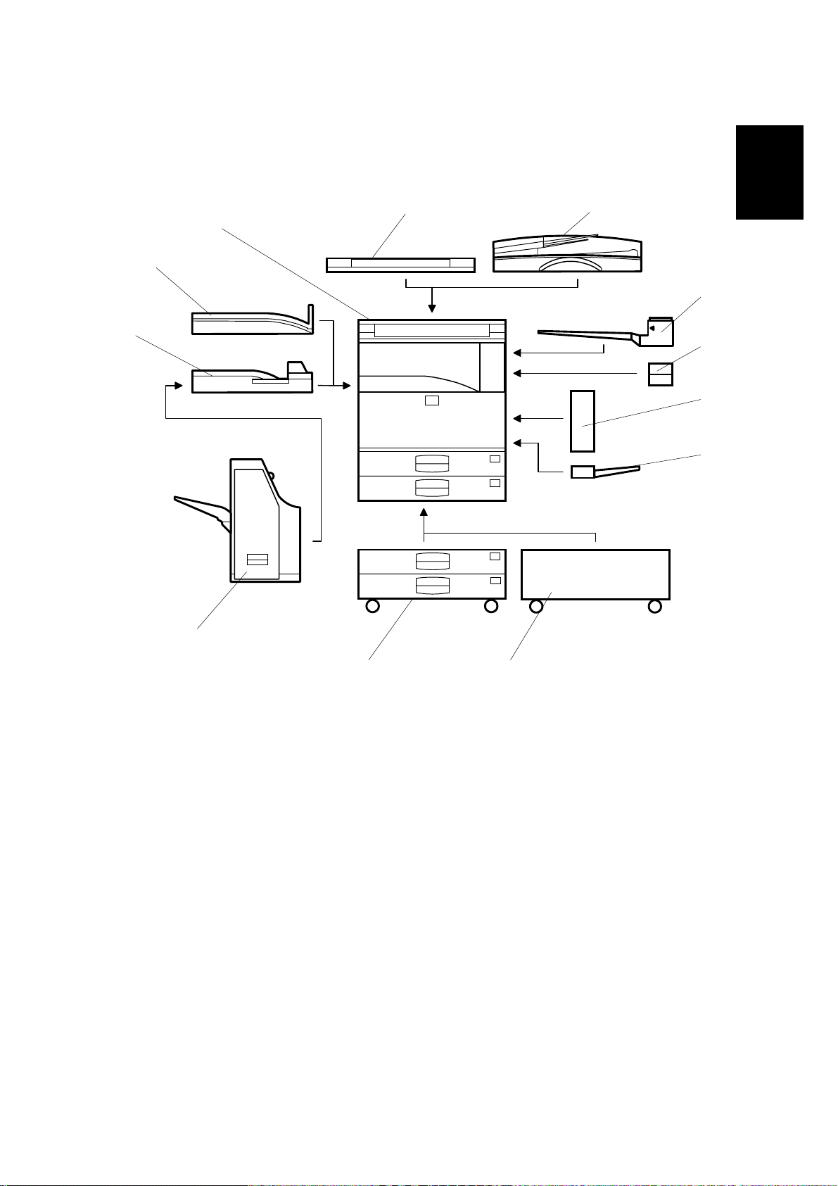
1.2 M ACHINE CONFIGUR ATION
1.2.1 SYSTEM COMPONENTS
2
1
12
3
4
Overall
Information
11
10
5
6
g
A265V501.WMF
7
89
1-5

MACHINE CONFIGURATION 20 September 1999
Version Item Machine Code
Copier
Copier (Russian-C1A) A265 1
Copier (Russian-C1B) A267 1
ARDF (Optional) A858 3
Platen Cover (Optional) A893 Stinger-C 2
Paper Tray Unit - 2 tray (Optional) A860-11, -21,
-56
LCT (Optional) A862 8
1-bin Tray (Optional) A898 4
Shift Tray (Optional) B313 12
Duplex Unit (Optional) A896 6
By-pass Tray (Optional) A899 7
Interchange Unit (Optional) B300 5
Bridge Unit (Optional) A897 11
1000-sheet Finisher (Optional) A681 NAD 10
Copier Feature Expander - Memory
A887 Stinger-C
48 MB (Optional)
Key Counter Bracket Adam
Fax
Fax Controller (Optional) A895-01, -02,
-03
G3 Interface Unit (Optional) A895-11, -12
Handset (Optional) H160 Adam
ISDN (Optional) A895-21, -22
PC Fax Expander (Optional) A894 Stinger-C
Fax Function Expander (Optional) A892 Stinger-C
Printer
Printer Controller (Optional) B306
PostScript Kit (Optional) B308 Stinger-C
HDD (Optional) G690 Stinger-C
NIB (Optional) B307 Stinger-C
Memory 32 or 64 MB (Optional) G688 Stinger-C
Scanner Scanner Controller (Optional) A844
Common
with
No.
9
1-6

20 September 1999 MACHINE CONFIGURATION
1.2.2 INSTALLABLE OPTION TABLE
Copier options
No. Option
1 ARDF (O ptional)
2 Platen Cover (Opt ional)
3 Paper Tray Unit - 2 tray (Optional)
4 LCT (Optional)
5 1-bin Tray (Optional)
6 Shift Tray (Optional)
7 Duplex Unit (Optional)
8 By-pass Tray (Optional)
9 Int erchange Unit (Optional)
10 Bridge Unit (Optional)
11 1000-sheet Finisher (Optional)
12 Memory 48 MB (Optional)
13 Key Counter Bracket
•
= Available
∆
= Requires another option
RussianC1A/C1B
•
•
•
•
∆
•
∆
•
•
∆
∆
•
•
Note
Install either no. 1 or 2
Install either no. 1 or 2
Install either no. 3 or 4
Install either no. 3 or 4
Requires no.9
Install either no. 6 or 10
Requires no.9
No. 10 requires no.11
Install either no. 6 or 10
Requires no.10, 12 and
either no.3 or 4
Overall
Information
Fax and printer options
All options for the fax and printer units are avail abl e when these uni ts have been
installed.
Scanner option
When the scanner option is installe d, the printer option must be installed.
1-7
PAPER PATH 20 September 1999
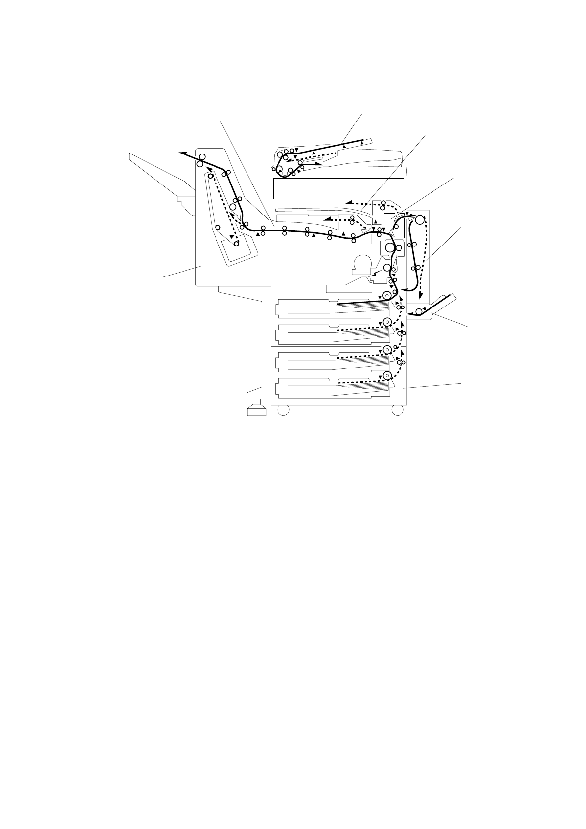
1.3 PAPER PATH
8
1
2
3
4
7
5
6
1. Optional ADF
2. Optional 1-bin Tray
3. Optional Interchange Unit
4. Optional Duplex Unit
5. Optional By-pass Feed Tray
6. Optional Paper Tray Unit
7. Optional 1000-sheet Finisher
8. Optional Bridge Unit
A267V102.WMF
1-8
20 September 1999 MECHANICAL COMPONENT LAYOUT
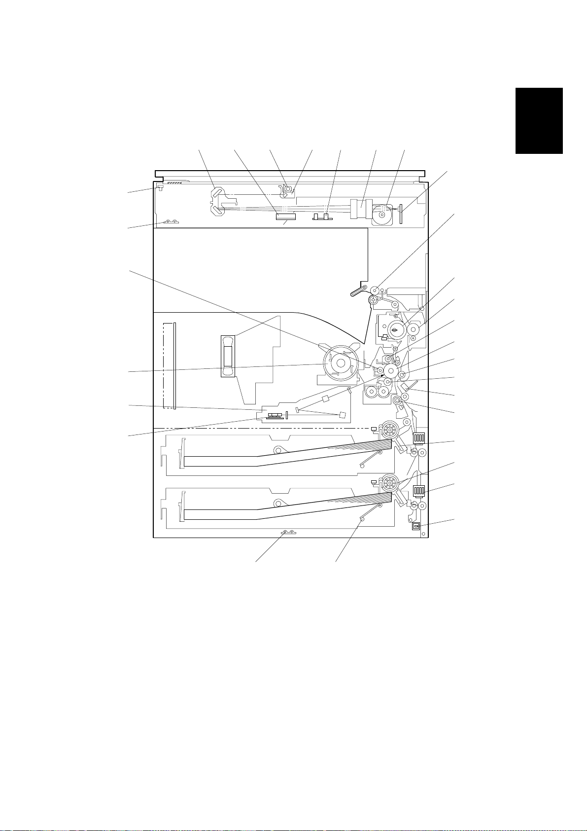
1.4 MECH ANICAL COMPONENT LAYOUT
1 2 3 4 5 6 7
8
29
9
28
Overall
Information
27
26
25
24
10
11
12
13
14
15
16
17
18
19
20
21
A265V100.WMF
2223
1-9

MECHANICAL COMPONENT LAYOUT 20 September 1999
1. 2nd scanner
2. Original width sensor
3. Exposure lamp
4. 1st scanner
5. Original length sensor
6. Lens
7. Scanner motor
8. SBU board
9. Exit roller
10. Fusing hot roller
11. Fusing pressure roller
12. Cleaning unit
13. OPC drum
14. Transfer roller
15. Development roller
16. ID sensor
17. Registration roller
18. Friction pad
19. Paper feed roller
20. Paper size sensor
21. Special paper sensor
22. Bottom plate
23. Tray heater
24. Polygon mirror motor
25. Laser unit
26. Toner supply bottle holder
27. Drum charge roller
28. Anti-condensation heater
29. Scanner home position sensor
1-10

20 September 1999 ELECTRICAL COMPONENT DESCRIPTIONS
1.5 ELECTRIC AL COMPONENT DESCRIPTIONS
Refer to the electrical component layout on the reverse side of the point-to-point
diagram for the location of the components.
Symbol Name Function
Motors
M1 Scanner Drives the 1st and 2nd scanners.
M2 Polygonal Mirr or Turns the polygonal mirror.
M3 Main Drives the main unit components.
M4 Exhaust Fan Removes heat from around the fusing unit.
M5 Upper Paper Lift Raises the bottom plate in the 1st paper tray.
M6 Lower Paper Lift Raises the bottom plate in the 2nd paper tray.
M7
Magnetic Clutches
MC1 Upper Paper Feed Star ts paper feed from the 1st paper tray.
MC2 Lower Paper Feed Starts paper feed from the 2nd paper tray.
MC3 Upper Relay Dr ives the upper relay rollers.
MC4 Lower Relay Drives the lower relay rollers.
MC4 Registration Drives the registration rollers.
Toner Supply Rotates the toner bottle to supply toner to the
development unit.
Overall
Information
Switches
SW1 Main
SW2 Right Upper Cover
SW3 Right Cover
SW4 Right Lower Cover
SW5 Upper Paper Size
SW6 Lower Paper Size
SW7 Special Paper
SW8 New PCU Detect Detects when a new PCU is installed.
SW9 Front Cover Safety
SW10 Operation
Provides power to the machine. If this is off, there
is no power supplied to the machine.
Detects whether the right upper cover is open or
not.
Cuts the +5VLD and +24V dc power line and
detects whether the right cover is open or not.
Detects whether the right lower cover is open or
not.
Determines what size of paper is in the upper
paper tray.
Determines what size of paper is in the lower
paper tray.
Determines whether there is special paper in the
lower paper tray.
Cuts the +5VLD and +24V dc power line and
detects whether the front cover is open or not.
Provides power for machine operation. The
machine still has power if this switch is off.
1-11

ELECTRICAL COMPONENT DESCRIPTIONS 20 September 1999
Symbol Name Function
Sensors
S1 Scanner HP
Informs the CPU when the 1st and 2nd scanners
are at home position.
Informs the CPU that the platen cover is in the up
S2 Platen Cover
or down position (related to the APS/ARE
functions).
S2 Original Width
S4 Original Length 1
S5 Original Length 2
S6 Toner Density (TD)
S7 1st Paper End
S8 2nd Paper End
S9 Image Density (ID)
Detects original width. This is one of the APS
(Auto Paper Select) sensors.
Detects original length. This is one of the APS
(Auto Paper Select) sensors.
Detects original length. This is one of the APS
(Auto Paper Select) sensors.
Detects the amount of toner inside the
development unit.
Informs the CPU when the 1st paper tray runs out
of pap er.
Informs the CPU when the 2nd paper tray runs out
of pap er.
Detects the density of various patterns and the
reflectivity of the drum for process control.
S10 Paper Overflow Detects paper overflow in the built-in copy tray.
S11 Paper Exit Detects misfeeds.
S12 Upper Relay Detects misfeeds.
S13 Lower Relay Detects misfeeds.
S14 Registration
S15 1st Paper Lift
S16 2nd Paper Lift
Detects misfeeds and controls registration clutch
off-on timin g.
Detects when the paper in the 1st paper tray is at
the feed height.
Detects when the paper in the 2nd paper tray is at
the feed height.
S17 1st Paper Height – 1 Detects the amount of paper in the 1st paper tray.
S18 1st Paper Height – 2 Detects the amount of paper in the 1st paper tray.
S19 2nd Paper Height – 1 Detects the amount of paper in the 2nd paper tray.
S20 2nd Paper Height – 2 Detects the amount of paper in the 2nd paper tray.
PCBs
PCB1
BICU (Base Engine and
Image Control Unit)
PCB2 PSU (Power Supply Unit)
PCB3 IOB (Input/Output Board)
PCB4 SBU (Sensor Board Unit)
Controls all base engine functions both directly
and through other control boards.
Provides dc power to the system and ac power to
the fusing lamp and heaters.
Controls the fusing lamp and the mechanical parts
of the machine.
Contains the CCD, and outputs a video signal to
the BICU board.
PCB5 Lamp Stabilizer Stabilizes the power to the exposure lamp.
PCB6 LDD (Laser Diode Driver) Controls the laser diode.
PCB7 Operation Panel Controls the operation panel.
1-12

20 September 1999 ELECTRICAL COMPONENT DESCRIPTIONS
Symbol Name Function
PCB8 High Voltage Supply
PCB9 Memory (Option)
Supplies high voltage to the drum charge roller,
development roller, and transfer roller.
Expands the memory capacity for the copier
features.
Lamps
L1 Exposure Lamp
Applies high intensity light to the original for
exposure.
L2 Fusing Lamp Heats the hot roller.
L3
Quenching Lamp Neut r alizes any charge remaining on the drum
surface after cleaning.
Heaters
H1
Anti-condensation
(Option)
Turns on when the main power switch is off to
prevent moisture from forming on the optics.
Turns on when the main power switch is off to
H2 Tray (Option)
prevent moisture from forming around the paper
trays.
Overall
Information
Others
TF1 Fusing Thermo fus e
Opens the fusing lamp circuit if the fusing unit
overheats.
TH1 Fusing Thermistor Detects the temperature of the hot roller.
LSD 1
Laser Synchronization
Detector
Detects the laser beam at the start of the main
scan.
CO1 Mechanical Counter Keeps track of the total number of prints made.
Used for control of authorized use. If this feature is
CO2 Key Counter (Option)
enabled for copying, copying will be impossible
until it is installed.
1-13
 Loading...