

Page 1
®
®
®
RICOH GROUP COMPANIES
B039/B040/B043/B120
SERVICE MANUAL
001129MIU
Page 2

Page 3

B039/B040/B043/B120
SERVICE MANUAL
RICOH GROUP COMPANIES
Page 4

Page 5

B039/B040/B043/B120
SERVICE MANUAL
001129MIU
Page 6

Page 7

It is the reader's responsibility when discussing the information contained within this
document to maintain a level of confidentiality that is in the best interest of Ricoh
Corporation and its member companies.
NO PART OF THIS DOCUMENT MAY BE REPRODUCED IN ANY
FASHION AND DISTRIBUTED WITHOUT THE PRIOR
PERMISSION OF RICOH CORPORATION.
All product names, domain names or product illustrations, including desktop images,
used in this document are trademarks, registered trademarks or the property of their
respective companies.
They are used throughout this book in an informational or editorial fashion only and for
the benefit of such companies. No such use, or the use of any trade name, or web
site is intended to convey endorsement or other affiliation with Ricoh products.
2001 RICOH Corporation. All rights reserved.
Page 8

Page 9

LEGEND
COMPANY PRODUCT CODE
GESTETNER LANIER RICOH SAVIN
B039 1502 5515 Aficio 1015 2515
B040 1802 5518 Aficio 1018 2518
B043 1802d 5518D Aficio 1018D 2518d
B120 (RLA only) 1312 LD013 Aficio 1113 -
DOCUMENTATION HISTORY
REV. NO. DATE COMMENTS
* 06/01 Original Printing
1 06/03 B120 (RLA only)
Page 10

Page 11

B039/B040/B043
TABLE OF CONTENTS
INSTALLATION
1 INSTALLATION ........................................................................... 1-1
1.1 INSTALLATION REQUIREMENTS...........................................................1-1
1.1.1 ENVIRONMENT...............................................................................1-1
1.1.2 MACHINE LEVEL.............................................................................1-2
1.1.3 MINIMUM SPACE REQUIREMENTS...............................................1-3
1.1.4 POWER REQUIREMENTS..............................................................1-3
1.2 COPIER INSTALLATION..........................................................................1-4
1.2.1 POWER SOCKETS FOR PERIPHERALS.......................................1-4
1.2.2 ACCESSORY CHECK......................................................................1-4
1.2.3 INSTALLATION PROCEDURE........................................................1-5
1.3 PLATEN COVER INSTALLATION............................................................1-8
1.3.1 ACCESSORY CHECK......................................................................1-8
1.3.2 INSTALLATION PROCEDURE........................................................1-8
1.4 ARDF INSTALLATION..............................................................................1-9
1.4.1 ACCESSORY CHECK......................................................................1-9
1.4.2 INSTALLATION PROCEDURE........................................................1-9
1.5 ADF INSTALLATION...............................................................................1-11
1.5.1 ACCESSORY CHECK....................................................................1-11
1.5.2 INSTALLATION PROCEDURE......................................................1-11
1.6 TWO-TRAY PAPER TRAY UNIT INSTALLATION..................................1-13
1.6.1 ACCESSORY CHECK....................................................................1-13
1.6.2 INSTALLATION PROCEDURE......................................................1-13
1.7 ONE-TRAY PAPER TRAY UNIT INSTALLATION...................................1-16
1.7.1 ACCESSORY CHECK....................................................................1-16
1.7.2 INSTALLATION PROCEDURE......................................................1-16
1.8 IMB INSTALLATION................................................................................1-19
1.8.1 ACCESSORY CHECK....................................................................1-19
1.8.2 INSTALLATION PROCEDURE......................................................1-19
1.9 DRAM INSTALLATION ...........................................................................1-20
1.10 ANTI-CONDENSATION HEATER INSTALLATION..............................1-21
1.11 TRAY HEATERS...................................................................................1-22
1.11.1 UPPER TRAY HEATER...............................................................1-22
1.11.2 LOWER TRAY HEATER (TWO-TRAY MODEL ONLY)................1-23
1.11.3 TRAY HEATERS FOR THE OPTIONAL PAPER FEED UNITS...1-24
1.12 KEY COUNTER INSTALLATION..........................................................1-27
PREVENTIVE MAINTENANCE
2 PREVENTIVE MAINTENANCE ................................................... 2-1
2.1 PM TABLES ..............................................................................................2-1
2.2 HOW TO CLEAR THE PM COUNTER......................................................2-3
SM i B039/B040/B043
Page 12

REPLACEMENT AND ADJUSTMENT
3 REPLACEMENT AND ADJUSTMENT......................................... 3-1
3.1 GENERAL CAUTIONS..............................................................................3-1
3.1.1 PCU (PHOTOCONDUCTOR UNIT) .................................................3-1
3.1.2 TRANSFER ROLLER.......................................................................3-1
3.1.3 SCANNER UNIT...............................................................................3-1
3.1.4 LASER UNIT ....................................................................................3-2
3.1.5 FUSING UNIT...................................................................................3-2
3.1.6 PAPER FEED...................................................................................3-2
3.1.7 IMPORTANT ....................................................................................3-2
3.2 SPECIAL TOOLS AND LUBRICANTS......................................................3-2
3.3 EXTERIOR COVERS & OPERATION PANEL..........................................3-3
3.3.1 REAR COVER..................................................................................3-3
3.3.2 REAR LOWER COVER (TWO-TRAY MODELS ONLY)...................3-3
3.3.3 COPY TRAY.....................................................................................3-4
3.3.4 LEFT UPPER COVER......................................................................3-4
3.3.5 FRONT UPPER LEFT COVER AND OPERATION PANEL.............3-4
3.3.6 RIGHT UPPER COVER...................................................................3-4
3.3.7 TOP REAR COVER..........................................................................3-4
3.3.8 LEFT COVER...................................................................................3-5
3.3.9 FRONT LONG COVER....................................................................3-5
3.3.10 FRONT RIGHT COVER .................................................................3-6
3.3.11 RIGHT REAR COVER....................................................................3-6
3.3.12 RIGHT DOOR.................................................................................3-7
3.3.13 BY-PASS TRAY..............................................................................3-8
3.3.14 LEFT LOWER COVER (TWO-TRAY MODELS ONLY)..................3-9
3.3.15 RIGHT LOWER COVER (TWO-TRAY MODELS ONLY)...............3-9
3.3.16 PLATEN COVER SENSOR............................................................3-9
3.4 SCANNER SECTION..............................................................................3-10
3.4.1 EXPOSURE GLASS/DF EXPOSURE GLASS...............................3-10
Exposure Glass ..................................................................................3-10
DF Exposure Glass.............................................................................3-10
3.4.2 LENS BLOCK.................................................................................3-11
3.4.3 EXPOSURE LAMP, LAMP STABILIZER BOARD..........................3-11
3.4.4 ORIGINAL WIDTH SENSOR..........................................................3-12
3.4.5 ORIGINAL LENGTH SENSOR.......................................................3-12
Sensor Positions.................................................................................3-12
3.4.6 CHANGING THE ORIGINAL SENSOR POSITIONS (8K/16K) ......3-13
Procedure...........................................................................................3-14
3.4.7 SCANNER MOTOR........................................................................3-15
3.4.8 SCANNER H.P. SENSOR..............................................................3-15
3.4.9 ADJUSTMENT OF 2ND SCANNER POSITION.............................3-16
3.4.10 ADJUSTMENT OF 1ST AND 2ND SCANNER ALIGNMENT.......3-17
3.5 LASER UNIT...........................................................................................3-18
3.5.1 LOCATION OF “CAUTION” DECAL...............................................3-18
3.5.2 TONER SHIELD GLASS................................................................3-19
3.5.3 LASER UNIT ..................................................................................3-19
B039/B040/B043 ii SM
Page 13

3.5.4 LD UNIT..........................................................................................3-20
3.5.5 POLYGONAL MIRROR MOTOR....................................................3-20
3.5.6 LASER UNIT ALIGNMENT ADJUSTMENT....................................3-21
3.6 PCU SECTION........................................................................................3-22
3.6.1 PCU................................................................................................3-22
3.6.2 PICK-OFF PAWLS.........................................................................3-22
3.6.3 TONER DENSITY SENSOR ..........................................................3-22
3.6.4 OPC DRUM....................................................................................3-23
3.6.5 CHARGE ROLLER AND CLEANING BRUSH................................3-24
3.6.6 CLEANING BLADE.........................................................................3-24
3.6.7 DEVELOPER..................................................................................3-25
3.6.8 AFTER REPLACEMENT OR ADJUSTMENT.................................3-26
3.7 TONER SUPPLY MOTOR ......................................................................3-27
3.8 PAPER FEED SECTION.........................................................................3-28
3.8.1 PAPER FEED ROLLER..................................................................3-28
3.8.2 FRICTION PAD..............................................................................3-28
3.8.3 PAPER END SENSOR...................................................................3-28
3.8.4 EXIT SENSOR ...............................................................................3-29
Non-duplex Models.............................................................................3-29
Duplex Models....................................................................................3-29
3.8.5 BY-PASS FEED ROLLER AND
BY-PASS PAPER END SENSOR..................................................3-30
3.8.6 REGISTRATION ROLLER .............................................................3-31
3.8.7 BY-PASS PAPER SIZE SENSOR..................................................3-32
3.8.8 REGISTRATION CLUTCH.............................................................3-32
3.8.9 REGISTRATION SENSOR.............................................................3-33
3.8.10 UPPER PAPER FEED CLUTCH AND
BY-PASS FEED CLUTCH............................................................3-33
3.8.11 RELAY CLUTCH..........................................................................3-34
3.8.12 RELAY SENSOR..........................................................................3-34
3.8.13 LOWER PAPER FEED CLUTCH
(TWO-TRAY MODELS ONLY) .....................................................3-34
3.8.14 VERTICAL TRANSPORT SENSOR
(TWO-TRAY MODELS ONLY) .....................................................3-35
3.8.15 PAPER SIZE SWITCH.................................................................3-35
3.9 IMAGE TRANSFER.................................................................................3-36
3.9.1 IMAGE TRANSFER ROLLER ........................................................3-36
3.9.2 IMAGE DENSITY SENSOR ...........................................................3-36
3.10 FUSING.................................................................................................3-37
3.10.1 FUSING UNIT...............................................................................3-37
3.10.2 THERMISTOR..............................................................................3-37
3.10.3 FUSING LAMP.............................................................................3-38
3.10.4 HOT ROLLER...............................................................................3-38
3.10.5 THERMOFUSE AND THERMOSTAT ..........................................3-39
3.10.6 HOT ROLLER STRIPPER PAWLS ..............................................3-39
3.10.7 PRESSURE ROLLER AND BUSHINGS......................................3-40
3.10.8 NIP BAND WIDTH ADJUSTMENT...............................................3-41
3.11 DUPLEX UNIT (DUPLEX MODELS ONLY)..........................................3-42
3.11.1 DUPLEX EXIT SENSOR..............................................................3-42
SM iii B039/B040/B043
Page 14

Rev. 03/2002
3.11.2 DUPLEX ENTRANCE SENSOR.................................................. 3-42
3.11.3 DUPLEX INVERTER SENSOR.................................................... 3-42
3.11.4 DUPLEX TRANSPORT MOTOR ................................................. 3-43
3.11.5 DUPLEX INVERTER MOTOR ..................................................... 3-43
3.11.6 DUPLEX CONTROL BOARD....................................................... 3-43
3.12 OTHER REPLACEMENTS ................................................................... 3-44
3.12.1 QUENCHING LAMP..................................................................... 3-44
3.12.2 HIGH-VOLTAGE POWER SUPPLY BOARD............................... 3-44
3.12.3 IMB (MEMORY BOARD).............................................................. 3-45
3.12.4 BICU (BASE-ENGINE IMAGE CONTROL UNIT) ........................ 3-45
3.12.5 IOB (I/O BOARD) ......................................................................... 3-46
3.12.6 MAIN MOTOR.............................................................................. 3-46
3.12.7 REAR EXHAUST FAN ................................................................. 3-46
3.12.8 LEFT EXHAUST FAN .................................................................. 3-47
3.12.9 PSU (POWER SUPPLY UNIT) .................................................... 3-47
3.12.10 GEARBOX ................................................................................. 3-48
Replacement Procedure..................................................................... 3-48
Gear Arrangement Within the Gearbox .............................................. 3-49
3.13 COPY ADJUSTMENTS: PRINTING/SCANNING.................................. 3-50
3.13.1 PRINTING .................................................................................... 3-50
Registration - Leading Edge/Side-to-Side .......................................... 3-50
Blank Margin ...................................................................................... 3-51
Main Scan Magnification .................................................................... 3-51
3.13.2 SCANNING .................................................................................. 3-52
Registration: Platen Mode .................................................................. 3-52
Magnification ...................................................................................... 3-53
Standard White Density Adjustment................................................... 3-54
3.13.3 ADF IMAGE ADJUSTMENT ........................................................ 3-55
Registration and Blank Margin ........................................................... 3-55
Sub-scan Magnification ...................................................................... 3-55
TROUBLESHOOTING
4 TROUBLESHOOTING ................................................................. 4-1
4.1 SERVICE CALL CONDITIONS................................................................. 4-1
4.1.1 SUMMARY....................................................................................... 4-1
4.1.2 SC CODE DESCRIPTIONS............................................................. 4-2
4.2 ELECTRICAL COMPONENT DEFECTS.................................................. 4-8
4.2.1 SENSORS........................................................................................ 4-8
4.2.2 SWITCHES ...................................................................................... 4-9
4.3 BLOWN FUSE CONDITIONS................................................................. 4-10
4.4 LED DISPLAY......................................................................................... 4-10
4.4.1 BICU............................................................................................... 4-10
4.4.2 IOB................................................................................................. 4-10
4.5 FIRMWARE MODIFICATION HISTORY…………………………………...4-11
SERVICE TABLES
5 SERVICE TABLES....................................................................... 5-1
B039/B040/B043 iv SM
Page 15

5.1 USING SERVICE PROGRAM MODES.....................................................5-1
Accessing SP Modes............................................................................5-1
Accessing Copy Mode from within an SP Mode...................................5-1
How to Select a Program Number........................................................5-2
To Input a Value or Setting for an SP Mode .........................................5-2
5.1.1 SP MODE TABLES..........................................................................5-3
SP1-XXX (Feed)...................................................................................5-3
SP2-XXX (Drum)...................................................................................5-6
SP4-XXX (Scanner)............................................................................5-11
SP5-XXX (Mode) ................................................................................5-17
SP6-XXX (Peripherals) .......................................................................5-24
SP7-XXX (Data Log)...........................................................................5-26
5.1.2 TEST PATTERN PRINTING (SP5-902).........................................5-31
5.1.3 INPUT CHECK (SP5-803)..............................................................5-32
5.1.4 OUTPUT CHECK (SP5-804)..........................................................5-36
Output Check Table............................................................................5-36
5.1.5 COPY JAM HISTORY (SP7-903)...................................................5-37
5.1.6 SMC PRINTING (SP5-992)............................................................5-38
5.1.7 ORIGINAL JAM HISTORY DISPLAY (SP7-905)............................5-38
5.1.8 MEMORY ALL CLEAR (SP5-801)..................................................5-39
Using a Flash Memory Card...............................................................5-39
Without Using a Flash Memory Card..................................................5-40
5.1.9 PROGRAM UPLOAD/DOWNLOAD...............................................5-41
Program Download (SP5-827)............................................................5-41
Program Upload (SP5-826) ................................................................5-42
5.1.10 NVRAM DATA UPLOAD/DOWNLOAD........................................5-43
NVRAM Data Download (SP5-825)....................................................5-43
NVRAM Data Upload (SP5-824).........................................................5-44
5.1.11 APS AND PLATEN/ADF COVER SENSOR
OUTPUT DISPLAY (SP4-301) .....................................................5-45
5.1.12 ADF APS SENSOR OUTPUT DISPLAY (SP6-901).....................5-46
5.1.13 SERIAL NUMBER INPUT (SP5-811) ...........................................5-47
5.1.14 ID SENSOR ERROR ANALYSIS (SP2-221)................................5-48
5.2 USER TOOLS.........................................................................................5-49
5.2.1 HOW TO ENTER AND EXIT USER TOOLS..................................5-49
5.2.2 USER TOOLS TABLE....................................................................5-49
System Setting Table..........................................................................5-49
Copy Features Table..........................................................................5-50
DETAILED SECTION DESCRIPTIONS
6 DETAILED SECTION DESCRIPTIONS ....................................... 6-1
6.1 OVERVIEW...............................................................................................6-1
6.1.1 COMPONENT LAYOUT...................................................................6-1
6.1.2 PAPER PATH...................................................................................6-3
6.1.3 DRIVE LAYOUT...............................................................................6-4
6.2 BOARD STRUCTURE...............................................................................6-5
6.2.1 BLOCK DIAGRAM............................................................................6-5
SM v B039/B040/B043
Page 16

1. BiCU (Base Engine and Image Control Unit)....................................6-6
2. IOB (I/O Board).................................................................................6-6
3. SBU (Sensor Board Unit)..................................................................6-6
4. IMB (IMAC and Memory Board)........................................................6-6
6.3 COPY PROCESS OVERVIEW .................................................................6-7
6.4 SCANNING................................................................................................6-9
6.4.1 OVERVIEW......................................................................................6-9
Lamp Stabilizer Fuse............................................................................6-9
6.4.2 SCANNER DRIVE..........................................................................6-10
6.4.3 ORIGINAL SIZE DETECTION IN PLATEN MODE.........................6-11
6.5 IMAGE PROCESSING............................................................................6-13
6.5.1 OVERVIEW....................................................................................6-13
6.5.2 SBU (SENSOR BOARD UNIT).......................................................6-14
6.5.3 AUTO IMAGE DENSITY (ADS)......................................................6-15
In the SBU ..........................................................................................6-15
In the IPU............................................................................................6-15
By Original Type.................................................................................6-15
6.5.4 IPU (IMAGE PROCESSING UNIT).................................................6-16
Overview.............................................................................................6-16
Image Processing Modes ...................................................................6-17
Image Processing Path.......................................................................6-18
Original Modes....................................................................................6-19
SP Modes for Each Image Processing Step.......................................6-19
Auto Shading......................................................................................6-21
White Line Erase ................................................................................6-22
Black Line Erase.................................................................................6-22
Scanner Gamma (γ) Correction..........................................................6-23
Main Scan Magnification.....................................................................6-24
Mirroring for ADF Mode ......................................................................6-24
Filtering...............................................................................................6-25
ID Gamma (γ) Correction....................................................................6-26
Gradation Processing.........................................................................6-27
6.5.5 IMB (MEMORY CONTROLLER AND DRAM)................................6-28
6.5.6 VIDEO CONTROL UNIT (VCU)......................................................6-29
Fine Character and Image (FCI).........................................................6-29
Printer Gamma Correction..................................................................6-29
6.6 LASER EXPOSURE................................................................................6-30
6.6.1 OVERVIEW....................................................................................6-30
6.6.2 AUTO POWER CONTROL (APC)..................................................6-31
6.6.3 LD SAFETY SWITCH.....................................................................6-32
6.7 PHOTOCONDUCTOR UNIT (PCU)........................................................6-33
6.7.1 OVERVIEW....................................................................................6-33
6.7.2 DRIVE.............................................................................................6-34
6.8 DRUM CHARGE .....................................................................................6-35
6.8.1 OVERVIEW....................................................................................6-35
6.8.2 CHARGE ROLLER VOLTAGE CORRECTION..............................6-36
Correction for Environmental Conditions............................................6-36
6.8.3 ID SENSOR PATTERN PRODUCTION TIMING............................6-37
6.8.4 DRUM CHARGE ROLLER CLEANING..........................................6-38
B039/B040/B043 vi SM
Page 17

6.9 DEVELOPMENT .....................................................................................6-39
6.9.1 OVERVIEW....................................................................................6-39
6.9.2 DRIVE.............................................................................................6-40
6.9.3 DEVELOPER MIXING....................................................................6-40
6.9.4 DEVELOPMENT BIAS...................................................................6-41
6.9.5 TONER SUPPLY............................................................................6-42
Toner Bottle Replenishment Mechanism............................................6-42
Toner Supply Mechanism...................................................................6-43
6.9.6 TONER DENSITY CONTROL........................................................6-44
Overview.............................................................................................6-44
Toner Density Sensor Initial Setting....................................................6-46
Toner Concentration Measurement....................................................6-46
Vsp/Vsg Detection..............................................................................6-46
Toner Supply Reference Voltage (Vref) Determination.......................6-46
Toner Supply Determination...............................................................6-46
Toner Supply Motor On Time Determinations.....................................6-47
6.9.7 TONER SUPPLY IN ABNORMAL SENSOR CONDITIONS...........6-48
ID Sensor............................................................................................6-48
TD Sensor...........................................................................................6-48
6.9.8 TONER NEAR END/END DETECTION AND RECOVERY ............6-49
Toner Near End Detection..................................................................6-49
Toner Near End Recovery..................................................................6-49
Toner End Detection...........................................................................6-49
Toner End Recovery...........................................................................6-49
6.10 DRUM CLEANING AND TONER RECYCLING.....................................6-50
6.10.1 DRUM CLEANING........................................................................6-50
6.10.2 TONER RECYCLING...................................................................6-50
6.11 PAPER FEED........................................................................................6-51
6.11.1 OVERVIEW..................................................................................6-51
6.11.2 PAPER FEED DRIVE MECHANISM............................................6-52
6.11.3 PAPER FEED AND SEPARATION MECHANISM........................6-52
6.11.4 PAPER LIFT MECHANISM..........................................................6-53
6.11.5 PAPER END DETECTION...........................................................6-53
6.11.6 PAPER SIZE DETECTION...........................................................6-54
Paper Tray..........................................................................................6-54
By-pass Tray.......................................................................................6-55
6.11.7 SIDE FENCES..............................................................................6-56
6.11.8 PAPER REGISTRATION..............................................................6-56
6.12 IMAGE TRANSFER AND PAPER SEPARATION.................................6-57
6.12.1 OVERVIEW..................................................................................6-57
6.12.2 IMAGE TRANSFER CURRENT TIMING......................................6-58
6.12.3 TRANSFER ROLLER CLEANING................................................6-59
6.12.4 PAPER SEPARATION MECHANISM...........................................6-59
6.13 IMAGE FUSING AND PAPER EXIT......................................................6-60
6.13.1 OVERVIEW..................................................................................6-60
6.13.2 FUSING DRIVE AND RELEASE MECHANISM...........................6-60
6.13.3 FUSING ENTRANCE GUIDE SHIFT............................................6-61
6.13.4 PRESSURE ROLLER...................................................................6-61
6.13.5 FUSING TEMPERATURE CONTROL..........................................6-62
SM vii B039/B040/B043
Page 18

Rev. 03/2002
Overview ............................................................................................ 6-62
Fusing Lamp Control .......................................................................... 6-64
Fusing Temperature Control for Thick Paper at the By-pass Tray ..... 6-65
Pre-heat Mode (Fusing Idling) ............................................................ 6-65
To Prevent Offset when Making Multiple Copies
on Small-width Paper ......................................................................... 6-65
Reduced Copy Speed with Narrow Paper.......................................... 6-65
6.13.6 OVERHEAT PROTECTION ......................................................... 6-66
6.14 DUPLEX UNIT ...................................................................................... 6-67
6.14.1 OVERALL..................................................................................... 6-67
6.14.2 DRIVE MECHANISM ................................................................... 6-68
6.14.3 BASIC OPERATION .................................................................... 6-69
Larger than A4 Short-edge/LT Short-edge ......................................... 6-69
Up to A4 Short-edge/LT Short-edge................................................... 6-70
6.14.4 FEED IN AND EXIT MECHANISM............................................... 6-71
6.15 ENERGY SAVER MODES.................................................................... 6-72
6.15.1 OVERVIEW.................................................................................. 6-72
6.15.2 LOW POWER MODE................................................................... 6-73
Entering Low Power Mode ................................................................. 6-73
What Happens in Low Power Mode ................................................... 6-73
Returning to Stand-by Mode............................................................... 6-74
6.15.3 NIGHT/OFF MODE ...................................................................... 6-74
Entering Night/Off Mode..................................................................... 6-74
What Happens in Night/Off Mode....................................................... 6-75
Returning to Stand-by Mode............................................................... 6-75
AUTO REVERSE DOCUMENT FEEDER B379
1 OVERALL MACHINE INFORMATION ......................................... 7-1
1.1 MECHANICAL COMPONENT LAYOUT................................................... 7-1
1.2 ELECTRICAL COMPONENT LAYOUT .................................................... 7-2
1.3 DRIVE LAYOUT........................................................................................ 7-3
2 DETAILED SECTION DESCRIPTIONS........................................ 7-4
2.1 ORIGINAL SIZE DETECTION .................................................................. 7-4
2.2 PICK-UP AND SEPARATION................................................................... 7-6
2.3 ORIGINAL TRANSPORT AND EXIT ........................................................ 7-7
2.3.1 SINGLE-SIDED ORIGINALS ........................................................... 7-7
2.3.2 DOUBLE-SIDED ORIGINALS.......................................................... 7-8
2.3.3 ORIGINAL TRAILING EDGE SENSOR ........................................... 7-9
2.4 STAMP.................................................................................................... 7-10
2.5 TIMING CHARTS.................................................................................... 7-11
2.5.1 SINGLE-SIDED ORIGINAL MODE (A3) ........................................ 7-11
2.5.2 SINGLE-SIDED ORIGINAL MODE (A3, STAMP MODE) .............. 7-12
2.5.3 DOUBLE-SIDED ORIGINAL MODE .............................................. 7-13
2.5.4 DOUBLE-SIDED ORIGINAL MODE (STAMP MODE) ................... 7-14
2.6 JAM DETECTION ................................................................................... 7-15
B039/B040/B043 viii SM
Page 19

2.7 OVERALL ELECTRICAL CIRCUIT .........................................................7-16
2.8 FREE RUN.............................................................................................. 7-17
Procedure...........................................................................................7-17
One-sided Free Run Process.............................................................7-17
Two-sided Free Run Process.............................................................7-17
3 REPLACEMENT AND ADJUSTMENT....................................... 7-18
3.1 DF EXIT TABLE AND COVER................................................................7-18
3.2 ORIGINAL FEED UNIT ...........................................................................7-19
3.3 LEFT COVER..........................................................................................7-20
3.4 PICK-UP ROLLER...................................................................................7-21
3.5 FEED BELT.............................................................................................7-22
3.6 SEPARATION ROLLER..........................................................................7-23
3.7 ORIGINAL SET/ORIGINAL REVERSE SENSORS.................................7-24
3.8 ORIGINAL L/W SENSOR, TRAILING EDGE SENSOR..........................7-25
3.9 FEED CLUTCH, PICK-UP SOL, TRANSPORT MOTOR,
FEED MOTOR.........................................................................................7-26
Exterior ...............................................................................................7-26
DF Feed Clutch...................................................................................7-26
Pick-up Solenoid.................................................................................7-26
Transport Motor..................................................................................7-26
DF Feed Motor....................................................................................7-26
3.10 REGISTRATION SENSOR....................................................................7-27
3.11 STAMP SOLENOID AND ORIGINAL EXIT SENSOR...........................7-28
DOCUMENT FEEDER B387
1 OVERALL INFORMATION .......................................................... 8-1
1.1 MECHANICAL COMPONENT LAYOUT ...................................................8-1
1.2 ELECTRICAL COMPONENT LAYOUT.....................................................8-2
1.3 DRIVE LAYOUT........................................................................................8-3
2 DETAILED SECTION DESCRIPTIONS ....................................... 8-4
2.1 ORIGINAL SIZE DETECTION...................................................................8-4
2.2 PICK-UP AND SEPARATION...................................................................8-6
2.3 ORIGINAL TRANSPORT AND EXIT MECHANISM..................................8-7
2.4 STAMP......................................................................................................8-8
2.5 TIMING CHARTS......................................................................................8-9
2.5.1 A3.....................................................................................................8-9
2.5.2 A3, STAMP MODE.........................................................................8-10
2.6 JAM DETECTION....................................................................................8-11
2.7 OVERALL ELECTRICAL CIRCUIT .........................................................8-12
2.8 FREE RUN..............................................................................................8-13
Procedure...........................................................................................8-13
Free Run Process...............................................................................8-13
SM ix B039/B040/B043
Page 20

3 REPLACEMENT AND ADJUSTMENT....................................... 8-14
3.1 EXTERIOR COVERS..............................................................................8-14
3.1.1 REAR COVER................................................................................8-14
3.1.2 ORIGINAL TABLE..........................................................................8-14
3.1.3 FRONT COVER .............................................................................8-14
3.1.4 ORIGINAL ENTRANCE GUIDE .....................................................8-14
3.1.5 DF FEED COVER...........................................................................8-15
3.2 FEED UNIT..............................................................................................8-15
3.3 SEPARATION ROLLER..........................................................................8-15
3.4 PICK-UP ROLLER...................................................................................8-16
3.5 FEED BELT.............................................................................................8-16
3.6 ORIGINAL SENSORS (WIDTH, LENGTH, TRAILING EDGE)................8-17
3.7 ORIGINAL SET SENSOR.......................................................................8-18
3.8 TRANSPORT MOTOR............................................................................8-18
3.9 DF COVER OPEN SENSOR/FEED CLUTCH/ROM/
DF DRIVE BOARD..................................................................................8-19
Exterior ...............................................................................................8-19
Feed Cover Open Sensor...................................................................8-19
Feed Clutch ........................................................................................8-19
ROM ...................................................................................................8-19
DF Drive Board...................................................................................8-19
3.10 REGISTRATION SENSOR....................................................................8-21
3.11 PICK-UP SOLENOID ............................................................................8-21
3.12 STAMP SOLENOID............................................................................... 8-22
PAPER TRAY UNIT B384
1 OVERALL MACHINE INFORMATION......................................... 9-1
1.1 MECHANICAL COMPONENT LAYOUT ...................................................9-1
1.2 ELECTRICAL COMPONENT LAYOUT.....................................................9-2
1.3 DRIVE LAYOUT........................................................................................9-3
2 DETAILED DESCRIPTIONS........................................................ 9-4
2.1 PAPER FEED AND SEPARATION MECHANISM....................................9-4
2.2 PAPER LIFT MECHANISM.......................................................................9-5
2.3 PAPER END DETECTION........................................................................9-7
2.4 PAPER HEIGHT DETECTION..................................................................9-8
PAPER SIZE DETECTION...................................................................9-9
2.5 SIDE AND END FENCES .......................................................................9-10
Side Fences........................................................................................9-10
End Fence ..........................................................................................9-10
3 REPLACEMENT AND ADJUSTMENT....................................... 9-11
3.1 FEED ROLLER REPLACEMENT............................................................9-11
3.2 TRAY MAIN BOARD REPLACEMENT ...................................................9-12
3.3 TRAY MOTOR REPLACEMENT.............................................................9-12
B039/B040/B043 x SM
Page 21

3.4 RELAY CLUTCH REPLACEMENT.........................................................9-13
3.5 UPPER PAPER FEED CLUTCH REPLACEMENT.................................9-14
3.6 LOWER PAPER FEED CLUTCH REPLACEMENT................................9-15
3.7 LIFT MOTOR REPLACEMENT...............................................................9-16
3.8 PAPER END SENSOR REPLACEMENT................................................9-17
3.9 VERTICAL TRANSPORT SENSOR REPLACEMENT............................9-17
3.10 PAPER SIZE SWITCH REPLACEMENT ..............................................9-18
PAPER TRAY UNIT B385
1 OVERALL MACHINE INFORMATION....................................... 10-1
1.1 MECHANICAL COMPONENT LAYOUT .................................................10-1
1.2 ELECTRICAL COMPONENT LAYOUT...................................................10-2
1.3 DRIVE LAYOUT......................................................................................10-3
2 DETAILED DESCRIPTIONS...................................................... 10-4
2.1 PAPER FEED AND SEPARATION.........................................................10-4
2.2 PAPER LIFT MECHANISM.....................................................................10-5
2.3 PAPER END DETECTION......................................................................10-7
2.4 PAPER HEIGHT DETECTION................................................................10-8
2.5 PAPER SIZE DETECTION......................................................................10-9
2.6 SIDE AND END FENCES .....................................................................10-10
Side Fences......................................................................................10-10
End Fence ........................................................................................10-10
3 REPLACEMENT AND ADJUSTMENT..................................... 10-11
3.1 FEED ROLLER REPLACEMENT..........................................................10-11
3.2 TRAY MAIN BOARD REPLACEMENT .................................................10-12
3.3 TRAY MOTOR REPLACEMENT...........................................................10-13
3.4 LIFT MOTOR REPLACEMENT.............................................................10-14
3.5 PAPER END SENSOR REPLACEMENT..............................................10-15
3.6 PAPER SIZE SWITCH REPLACEMENT ..............................................10-15
SPECIFICATIONS
SPECIFICATIONS.......................................................................... 11-1
1. GENERAL SPECIFICATIONS..................................................................11 -1
Duplex Unit (B043 only).....................................................................11 -4
2. MACHINE CONFIGURATION..................................................................11 -5
3. OPTIONAL EQUIPMENT.........................................................................11 -6
ARDF.................................................................................................11 -6
ADF....................................................................................................11 -7
ONE-TRAY PAPER TRAY UNIT.......................................................11 -8
TWO-TRAY PAPER TRAY UNIT.......................................................11 -9
16MB IMB (Copier Memory Unit)*......................................................11 -9
SM xi B039/B040/B043
Page 22

Rev. 06/2003
B120 (RLA ONLY)
B120 (RLA ONLY)
12.1 INSTALLATION .................................................................................... 12-1
12.2 PREVENTIVE MAINTENANCE SCHEDULES .................................... 12 -1
12.3 REPLACEMENT AND ADJUSTMENT ................................................ 12 -1
12.4 TROUBLESHOOTING......................................................................... 12 -1
12.5 SERVICE TABLES .............................................................................. 12 -1
12.5.1 SP MODE TABLES....................................................................... 12-1
12.5.2 COPY FEATURES TABLE (USER TOOLS) ................................. 12-2
System Setting Table ......................................................................... 12-2
Copy Features Table.......................................................................... 12-2
12.6 DETAILED SECTION DESCRIPTIONS............................................... 12 -3
12.7 SPECIFICATIONS .............................................................................. 12 -3
B039/B040/B043 xii SM
Page 23

Rev. 06/2003
B404
TABLE OF CONTENTS
INSTALLATION
1 INSTALLATION............................................................................. 1-1
1.1 INSTALLATION REQUIREMENTS ...........................................................1-1
1.1.1 ENVIRONMENT ...............................................................................1-1
1.1.2 MACHINE LEVEL.............................................................................1-1
1.1.3 MINIMUM SPACE REQUIREMENTS...............................................1-1
1.1.4 POWER REQUIREMENTS ..............................................................1-1
1.2 FAX UNIT ..................................................................................................1-2
1.2.1 ACCESSORY CHECK......................................................................1-2
1.2.2 INSTALLATION PROCEDURE ........................................................1-3
1.3 HANDSET .................................................................................................1-7
1.3.1 ACCESSORY CHECK......................................................................1-7
1.3.2 INSTALLATION PROCEDURE ........................................................1-7
PREVENTIVE MAINTENANCE
2 PREVENTIVE MAINTENANCE..................................................... 2-1
2.1 SPECIAL TOOLS AND LUBRICANTS ......................................................2-1
2.2 PM TABLE................................................................................................. 2-1
REMOVAL AND REPLACEMENT
3 REMOVAL AND REPLACEMENT................................................ 3-1
3.1 PRECAUTION ...........................................................................................3-1
3.2 FCU ...........................................................................................................3-1
3.3 NCU...........................................................................................................3-2
3.4 SPEAKER..................................................................................................3-3
TROUBLESHOOTING
4 TROUBLESHOOTING .................................................................. 4-1
4.1 ERROR CODES........................................................................................4-1
4.2 FAX SC CODES........................................................................................4-9
4.2.1 OVERVIEW ......................................................................................4-9
4.2.2 SC1201.............................................................................................4-9
4.2.3 FAX SC CODE TABLE ...................................................................4-10
4.3 FAX OPTION FIRMWARE MODIFICATION HISTORY…………………..4-11
SM xiii B039/B040/B043
Page 24

Rev. 06/2003
SERVICE TABLES
5 SERVICE TABLES........................................................................ 5-1
5.1 SERVICE LEVEL FUNCTIONS ................................................................ 5-1
5.1.1 HOW TO ENTER AND EXIT SERVICE MODE ............................... 5-1
5.1.2 FUNCTION NO. ............................................................................... 5-1
(1) 01. BIT SW ..................................................................................... 5-1
(2) 02. PARAMETER LIST................................................................... 5-2
(3) 03. ERROR CODE ......................................................................... 5-2
(4) 04. SERVICE REPORT .................................................................. 5-2
(5) 05. PROTOCOL DUMP .................................................................. 5-3
(6) 06. MEMORY.................................................................................. 5-3
(7) 07. RAM CLEAR............................................................................. 5-4
(8) 08. NCU.......................................................................................... 5-4
(9) 09. ROM VERSION ........................................................................ 5-5
(10) 10. FILE PRINTOUT..................................................................... 5-5
(11) 11. JOURNAL (ALL) ..................................................................... 5-5
(12) 12. RAM TEST.............................................................................. 5-6
(13) 13. S.S. NUMBER ........................................................................ 5-6
(14) 14. SERIAL # ................................................................................ 5-6
(15) 15. HISTORY................................................................................ 5-7
5.2 DATA TRANSFER.................................................................................... 5-8
5.2.1 FAX SOFTWARE DOWNLOAD....................................................... 5-8
5.2.2 FAX SRAM DOWNLOAD ................................................................ 5-9
5.2.3 FAX SRAM UPLOAD..................................................................... 5-10
5.3 BIT SWITCHES ...................................................................................... 5-11
5.3.1 SYSTEM SWITCHES .................................................................... 5-11
5.3.2 SCANNER SWITCHES ................................................................. 5-22
5.3.3 PLOTTER SWITCHES .................................................................. 5-27
5.3.4 COMMUNICATION SWITCHES .................................................... 5-32
5.3.5 G3 SWITCHES .............................................................................. 5-37
5.4 NCU PARAMETERS .............................................................................. 5-45
5.5 DEDICATED TRANSMISSION PARAMETERS ..................................... 5-56
5.5.1 PROGRAMMING PROCEDURE ................................................... 5-56
5.5.2 PARAMETERS .............................................................................. 5-57
5.6 SERVICE RAM ADDRESSES ................................................................ 5-60
DETAILED SECTION DESCRIPTIONS
6 DETAILED SECTION DESCRIPTIONS ........................................ 6-1
6.1 OPERATION DUMP LIST......................................................................... 6-1
6.2 PCBS ........................................................................................................ 6-2
6.2.1 FCU ................................................................................................. 6-2
6.2.2 NCU (US)......................................................................................... 6-4
6.2.3 NCU (EUROPE/ASIA) ..................................................................... 6-5
B039/B040/B043 xiv SM
Page 25

Rev. 06/2003
SPECIFICATIONS
SPECIFICATIONS............................................................................. 7-1
1. GENERAL SPECIFICATIONS.....................................................................7-1
2. FEATURES .................................................................................................7-2
2.1 FEATURES LIST................................................................................. 7-2
2.2 CAPABILITIES OF PROGRAMMABLE ITEMS ...................................7-5
3. OVERALL MACHINE CONTROL ................................................................7-6
3.1 SYSTEM CONTROL ...........................................................................7-6
3.2 POWER DISTRIBUTION.....................................................................7-6
3.3 MEMORY BACK-UP............................................................................7-6
4. VIDEO DATA PATH ....................................................................................7-7
4.1 TRANSMISSION ................................................................................. 7-7
Memory Transmission and Parallel Memory Transmission...................7-8
Immediate Transmission.......................................................................7-8
4.2 RECEPTION........................................................................................7-9
5. MACHINE CONFIGURATION................................................................... 7-10
FIRMWARE HISTORY
FIRMWARE HISTORY ...................................................................... 8-1
1. FIRMWARE MODIFICATION HISTORY .....................................................8-1
SM xv B039/B040/B043
Page 26

Page 27

!
IMPORTANT SAFETY NOTICES
PREVENTION OF PHYSICAL INJURY
1. Before disassembling or assembling parts of the copier and peripherals,
make sure that the power cord is unplugged.
2. The wall outlet should be near the copier and easily accessible.
3. Note that some components of the copier and the paper tray unit are
supplied with electrical voltage even if the main power switch is turned off.
4. If a job has started before the copier completes the warm-up or initializing
period, keep hands away from the mechanical and electrical components
because the starts making copies as soon as the warm-up period is
completed.
5. The inside and the metal parts of the fusing unit become extremely hot while
the copier is operating. Be careful to avoid touching those components with
your bare hands.
HEALTH SAFETY CONDITIONS
Toner and developer are non-toxic, but if you get either of them in your eyes by
accident, it may cause temporary eye discomfort. Try to remove with eye drops
or flush with water as first aid. If unsuccessful, get medical attention.
OBSERVANCE OF ELECTRICAL SAFETY STANDARDS
The copier and its peripherals must be installed and maintained by a customer
service representative who has completed the training course on those models.
SAFETY AND ECOLOGICAL NOTES FOR DISPOSAL
1. Do not incinerate toner bottles or used toner. Toner dust may ignite suddenly
when exposed to an open flame.
2. Dispose of used toner, developer, and organic photoconductors in
accordance with local regulations. (These are non-toxic supplies.)
3. Dispose of replaced parts in accordance with local regulations.
Page 28

LASER SAFETY
The Center for Devices and Radiological Health (CDRH) prohibits the repair of
laser-based optical units in the field. The optical housing unit can only be repaired
in a factory or at a location with the requisite equipment. The laser subsystem is
replaceable in the field by a qualified Customer Engineer. The laser chassis is not
repairable in the field. Customer engineers are therefore directed to return all
chassis and laser subsystems to the factory or service depot when replacement of
the optical subsystem is required.
!
WARNING
Use of controls, or adjustment, or performance of procedures other than
those specified in this manual may result in hazardous radiation exposure.
!
WARNING FOR LASER UNIT
WARNING: Turn off the main switch before attempting any of the
procedures in the Laser Unit section. Laser beams can
seriously damage your eyes.
CAUTION MARKING:
Symbols and Abbreviations
This manual uses several symbols and abbreviations. The meaning of those
symbols and abbreviations are as follows:
☛
!
"
#
SEF
LEF
See or Refer to
Clip ring
Screw
Connector
Short Edge Feed
Long Edge Feed
Page 29

INSTALLATION B039/B040/B043
Rev. 06/2003
PAPER TRAY UNIT B384
PREVENTIVE MAINTENANCE B039/B040/B043
PAPER TRAY UNIT B385
REPLACEMENT AND ADJUSTMENT B039/B040/B043
SPECIFICATIONS
TROUBLESHOOTING B039/B040/B043
FAX UNIT B404
TAB
POSITION 1
TAB
POSITION 2
TAB
POSITION 3
TAB
POSITION 4
SERVICE TABLES B039/B040/B043
B120 (RLA only)
DETAILED SECTION DESCRIPTION B039/B040/B043
AUTO REVERSE DOCUMENT FEEDER B379
DOCUMENT FEEDER B387
TAB
POSITION 5
TAB
POSITION 6
TAB
POSITION 7
TAB
POSITION 8
Page 30

Page 31

INSTALLATION
Page 32

Page 33

INSTALLATION REQUIREMENTS
1. INSTALLATION
!
CAUTION
Before installing options, please do the following:
1. If there is a fax unit in the machine, print out all messages stored in the
memory, the lists of user programmed items, and the system parameter
list.
2. If there is a printer option in the machine, print out all data in the printer
buffer.
3. Turn off the main switch and disconnect the power cord, the telephone
line, and the network cable.
1.1 INSTALLATION REQUIREMENTS
1.1.1 ENVIRONMENT
Installation
–Temperature and Humidity Chart–
Humidity
80%
54%
Operation range
15%
10°C
(50°F)
27°C
(80.6°F)
32°C
(89.6°F)
Temperature
B039I502.WMF
SM 1-1 B039/B040/B043
Page 34

INSTALLATION REQUIREMENTS
1. Temperature Range:
10°C to 32°C (50°F to 89.6°F)
2. Humidity Range: 15% to 80% RH
3. Ambient
Less than 1,500 lux (do not expose to direct sunlight).
Illumination:
4. Ventilation: Room air should turn over at least 30 m3/hr/person
5. Ambient Dust: Less than 0.075 mg/m3 (2.0 x 10⁻⁶ oz/yd3)
6. Avoid areas exposed to sudden temperature changes:
1) Areas directly exposed to cool air from an air conditioner.
2) Areas directly exposed to heat from a heater.
7. Do not place the machine where it will be expo s ed to corrosive gases.
8. Do not install the machine at any location over 2,000 m (6,500 ft.) above sea
level.
9. Place the copier on a strong and level base. (Inclination on any side should be
no more than 5 mm.)
10. Do not place the machine where it may be subjected to strong vibrations.
1.1.2 MACHINE LEVEL
Front to back: Within 5 mm (0.2") of level
Right to left: Within 5 mm (0.2") of level
B039/B040/B043 1-2 SM
Page 35

INSTALLATION REQUIREMENTS
1.1.3 MINIMUM SPACE REQUIREMENTS
Place the copier near the power source, providing clearance as shown:
[C]
[D][B]
A: Front > 750 mm (29.6")
B: Left > 10 mm (0.4")
C: Rear > 10 mm (0.4")
D: Right > 10 mm (0.4")
Installation
[A]
B039I145.WMF
NOTE: 1) The recommended 750 mm front space is sufficient to allow the paper
tray to be pulled out. Additional front space is required to allow
operators to stand at the front of the machine.
2) The recommended 10 mm right space is for installation only. Additional
right space is required to allow operators to fix paper jams and use the
by-pass tray.
1.1.4 POWER REQUIREMENTS
!
CAUTION
1. Make sure that the wall outlet is near the copier and easily accessible.
After completing installation, make sure the plug fits firmly into the
outlet.
2. Avoid multi-wiring.
3. Be sure to ground the machine.
1. Input voltage:
America, Taiwan:110 – 120 V, 50/60 Hz, 12 A
Europe, Asia: 220 – 240 V, 50/60 Hz, 7 A
SM 1-3 B039/B040/B043
Page 36

COPIER INSTALLATION
1.2 COPIER INSTALLATION
1.2.1 POWER SOCKETS FOR PERIPHERALS
!
CAUTION
Rated voltage for peripherals
Make sure to plug the cables into the correct sockets.
ADF/ARDF
Rated voltage output connector
for accessory Max. DC24 V
Paper Tray Unit
Rated voltage output connector
for accessory Max. DC24 V
1.1.2 ACCESSORY CHECK
Check that you have the accessories indicated below.
No. Description Q’ty
1 Operation Instructions - Sy st em Set t ings 1
2 Operation Instructions - Co py Reference 1
3 New Equipment Condition Report (NECR) - English
(-10, -17)
4
5 Model Nameplate (-10, -17, -22) 1
6 Model Name Decal (-22) 1
New Equipment Condition Report ( NECR) - Multi
Language (-19, -27, -29, -69)
B039I119.WMF
1
1
B039/B040/B043 1-4 SM
Page 37

COPIER INSTALLATION
1.1.3 INSTALLATION PROCEDURE
!
CAUTION
When installing the copier, make sure that the copier is unplugged.
1. Remove the strips of tape.
Installation
B039I102.WMF
2. Open the front door and remove the
toner bottle holder [A].
3. Open the right door, and remove the
PCU (Photoconductor Unit) [B].
[A]
B039I107.WMF
[B]
B039I108.WMF
SM 1-5 B039/B040/B043
Page 38

COPIER INSTALLATION
4. Separate the PCU into two sections
as shown (5 screws).
5. Distribute one pack of developer [A]
evenly across the width of the
development unit, into all openings.
NOTE: 1) To prevent foreign material
from getting on the sleeve
rollers, place a sheet of
paper under the
development unit.
2) Make sure not to spill the
developer on the gears [B].
3) If it is necessary to turn the
gear [B] to distribute the
developer, make sure to do
so very minimally, otherwise
the developer may spill.
6. Reassemble and reinstall the PCU.
7. Shake the toner bottle [C] several
times.
NOTE: Be sure not to remove the toner
bottle cap [D] until after
shaking.
B039I114.WMF
[A]
[B]
B039I115.WMF
[C]
[E]
[D]
8. Unscrew the bottle cap [D] and insert
the bottle into the holder.
NOTE: Do not touch the inner bottle
cap [E].
9. Reposition the holder and press down
the holder lever to secure the bottle.
B039I504.WMF
10. Pull out the paper tray and turn the
paper size dial to the appropriate size. Adjust the end and side guides to match
the paper size.
NOTE: To move the side guides, first release the green lock on the rear side
guide.
B039/B040/B043 1-6 SM
Page 39

COPIER INSTALLATION
11. Install the optional ARDF, ADF, or platen cover (☛ 1.3/1.4/1.5).
12. Plug in the main power cord and turn on the main switch. Perform TD Sensor
Initialization (SP2-214).
13. Select the correct display language using UP Mode (Language).
14. Load the paper in the paper tray and make a full size copy, and check if the
side-to-side and leading edge registrations are correct. If they are not, adjust
the registrations (☛ 3.13 Copy Adjustments: Printing/Scanning).
15. Initialize the electric total counter using SP7-825 in accordance with the type of
service contract.
NOTE: Select 1, then press the Original Type and OK keys at the same time. If
the reset is successful, “Action completed” will appear on the LCD.
Installation
SM 1-7 B039/B040/B043
Page 40

PLATEN COVER INSTALLATION
1.3 PLATEN COVER INSTALLATION
1.3.1 ACCESSORY CHECK
Check that you have the accessories indicated below.
No. Description Q’ty
1 Stepped Screw 2
1.3.2 INSTALLATION PROCEDURE
!
CAUTION
Unplug the machine power cord before starting the following procedure.
1. Install the platen cover [A] (2 screws).
[A]
B039I120.WMF
B039/B040/B043 1-8 SM
Page 41

1.4 ARDF INSTALLATION
1.4.1 ACCESSORY CHECK
ARDF INSTALLATION
Check the quantity and condition of the accessories against the following list.
No. Description Q’ty
1 Scale Guide 1
2DF Exposure Glass 1
3 Stud Screw 2
4 Knob Screw 2
5 Original Size Decal 2
6 Screwdriver Tool 1
34
6
1
2
5
B379I500.WMF
Installation
1.1.2 INSTALLATION PROCEDURE
1. Remove the strips of tape.
B379I101.WMF
SM 1-9 B039/B040/B043
Page 42

ARDF INSTALLATION
2. Remove the left scale [A] (2
screws).
3. Place the DF exposure glass
[B] on the glass holder.
NOTE: When installing the DF
exposure glass, make
sure that the white
point [C] is face down.
4. Peel off the backing [D] of the
double-sided tape attached to
the rear side of the scale guide
[E], then install it (2 screws
removed in step 2).
5. Install the two stud screws [F].
6. Mount the DF on the copier,
then slide the DF to the front.
7. Secure the DF unit with two
screws [G].
[C] [D]
[E]
[B]
[F]
B379I103.WMF
[A]
[F]
8. Connect the cable [H] to the
copier.
9. Attach the appropriate scale
decal [I] as shown.
10. Turn the main power switch
on. Then check if the
document feeder works
properly.
11. Make a full size copy, and
check that the side-to-side and
leading edge registrations are
correct. If they are not, adjust
the side-to-side and leading
edge registrations. (☛ 3.13.3
ADF Image Adjustment)
[G]
[H]
B379I104.WMF
[I]
B379I501.WMF
B039/B040/B043 1-10 SM
Page 43

1.5 ADF INSTALLATION
1.5.1 ACCESSORY CHECK
ADF INSTALLATION
Check the quantity and condition of the accessories against the following list.
No. Description Q’ty
1 Scale Guide 1
2DF Exposure Glass 1
3 Stud Screw 2
4 Fixing Screw 2
5 Original Size Decal 2
6 Screwdriver Tool 1
34
6
1
2
5
B387I500.WMF
Installation
1.5.2 INSTALLATION PROCEDURE
1. Remove the strips of tape.
B387I151.WMF
SM 1-11 B039/B040/B043
Page 44

ADF INSTALLATION
2. Remove the left scale [A] (2
screws).
3. Place the DF exposure glass
[B] on the glass holder.
NOTE: When installing the DF
exposure glass, make
sure that the white
point [C] is face down.
4. Peel off the backing [D] of the
double-sided tape attached to
the rear side of the scale guide
[E], then install it (2 screws
removed in step 2).
5. Install the two stud screws [F].
6. Mount the DF on the copier,
then slide the DF to the front.
7. Secure the DF unit with two
screws [G].
[C]
[D]
[E]
[B]
[F]
B387I103.WMF
[A]
[F]
8. Connect the cable [H] to the
copier.
9. Attach the appropriate scale
decal [I] as shown.
10. Turn the main power switch on.
Then check if the document
feeder works properly.
11. Make a full size copy, and
check that the side-to-side and
leading edge registrations are
correct. If they are not, adjust
the side-to-side and leading
edge registrations. (☛ 3.13.3
ADF Image Adjustment).
[G]
[H]
B387I104.WMF
[I]
B387I501.WMF
B039/B040/B043 1-12 SM
Page 45

TWO-TRAY PAPER TRAY UNIT INSTALLATION
1.6 TWO-TRAY PAPER TRAY UNIT INSTALLATION
1.6.1 ACCESSORY CHECK
Check the quantity and condition of the accessories against the following list.
No. Description Q’ty
1 Screw – M4x10 10
2 Unit Holder 4
3Adjuster 1
4 Unit Holder 2
1
2
3
4
B384I500.WMF
1.6.2 INSTALLATION PROCEDURE
Installation
[A]
B384I158.WMF
1. Remove the strips of tape.
NOTE: After removing the tape that secures the peripheral components and
cardboard to the paper tray, make sure that there is no tape and/or
tape residue remaining on the tray.
2. Attach the adjuster [A] to the base plate, as shown.
NOTE: If a table is installed, this step is unnecessary.
B384I001.WMF
SM 1-13 B039/B040/B043
Page 46

TWO-TRAY PAPER TRAY UNIT INSTALLATION
3. Remove the cover [A] (1 rivet).
4. Set the copier on the paper tray unit.
NOTE: When installing t he copier, be
careful not to pinch the
connecting harness.
[A]
B384I109.WMF
B384I117.WMF
5. One-tray copier model (B039):
Remove the 1st tray cassette [B].
Two-tray copier models
(B040/B043):
Remove the 2nd tray cassette
[B].
6. Install the two screws [C].
7. Reinstall the tray cassette.
B039/B040/B043 1-14 SM
[B]
[C]
B384I106.WMF
Page 47

8. Install the two brackets [A] (1
stepped screw each).
9. Connect the connecting harness
[B] to the copier.
NOTE: There are cutouts in the
plug on both sides. The
left side has one cutout,
and the right side has
two.
TWO-TRAY PAPER TRAY UNIT INSTALLATION
[A]
Installation
10. Reinstall the cover removed in
step 3 (1 rivet).
11. Install the four brackets [C] (2
screws each).
NOTE: If a table is installed, this
step is unnecessary.
12. Rotate the adjuster [D] to fix the
machine in place.
NOTE: If a table is installed, this
step is unnecessary.
13. Load the paper in the paper trays
and make full size copies from
each tray. Check if the side-toside and leading edge
registrations are correct. If they
are not, adjust the registrations
(☛ 3.13 Copy Adjustments:
Printing/ Scanning).
[B]
B384I105.WMF
[C]
B384I007.WMF
[D]
B384I002.WMF
SM 1-15 B039/B040/B043
Page 48

ONE-TRAY PAPER TRAY UNIT INSTALLATION
1.7 ONE-TRAY PAPER TRAY UNIT INSTALLATION
1.7.1 ACCESSORY CHECK
Check the quantity and condition of the accessories against the following list.
No. Description Q’ty
1 Screw – M4x10 2
2 Stepped Screw – M4x10 2
3 Unit Holder 2
1 2
1.7.2 INSTALLATION PROCEDURE
3
B385I500.WMF
B385I159.WMF
1. Remove the strips of tape.
NOTE: After removing the tape that secures the peripheral components and
cardboard to the paper tray, make sure that there is no tape and/or
tape residue remaining on the tray.
B039/B040/B043 1-16 SM
Page 49

ONE-TRAY PAPER TRAY UNIT INSTALLATION
2. Remove the cover [A] (1 rivet).
3. Set the copier on the paper tray unit.
NOTE: When installing t he copier, be
careful not to pinch the
connecting harness.
Installation
[A]
B385I109.WMF
B385I112.WMF
4. One-tray copier model (B039):
Remove the 1st tray cassette [B].
Two-tray copier models
(B040/B043):
Remove the 2nd tray cassette [B].
[B]
B385I120.WMF
SM 1-17 B039/B040/B043
Page 50

ONE-TRAY PAPER TRAY UNIT INSTALLATION
5. Install the two screws [A].
6. Reinstall the tray cassette.
[A]
B385I118.WMF
7. Install the two brackets [B]. (1 stepped
screw each).
8. Connect the connecting harness [C] to
the copier.
NOTE: There are cutouts in the plug
on both sides. The left side has
one cutout, and the right side
has two.
9. Reinstall the cover removed in step 2.
10. Load the paper in the paper tray and
make full size copies from tray. Check
if the side-to-side and leading edge
registrations are correct. If they are not,
adjust the registrations (☛ 3.13 Copy
Adjustments: Printing/Scanning).
[B]
[C]
B385I105.WMF
B039/B040/B043 1-18 SM
Page 51

1.8 IMB INSTALLATION
1.8.1 ACCESSORY CHECK
IMB INSTALLATION
Click the quantity and condition of the accessory against the following list:
No. Description Q’ty
1 Screw – M3x6 3
1.8.2 INSTALLATION PROCEDURE
[A]
[C]
Installation
B039I934.WMF
1. Remove the rear middle cover [A] (2 rivets).
2. Connect the connectors [B, C] and install the IMB [D] (3 screws).
3. Reinstall the rear middle cover.
[B]
[D]
B039I928.WMF
SM 1-19 B039/B040/B043
Page 52

DRAM INSTALLATION
1.9 DRAM INSTALLATION
[A]
B039I934.WMF
NOTE: The IMB must be installed before insta lling the DRAM.
1. Remove the rear middle cover [A] (2 rivets).
2. Install the DRAM [B].
3. Reinstall the rear middle cover.
[B]
B039R942.WMF
B039/B040/B043 1-20 SM
Page 53

ANTI-CONDENSATION HEATER INSTALLATION
1.10 ANTI-CONDENSATION HEATER INSTALLATION
[A]
[B]
[E]
[D]
1. Remove the exposure glass (☛ 3.4.1).
Installation
[C]
B039I127.WMF
2. Remove the left cover (☛ 3.3.8).
3. Pass the connector [A] through the opening [B].
4. Install the anti-condensation heater [C], as shown.
5. Join the connectors [A, D].
6. Clamp the harness with the clamp [E].
7. Reinstall the left cover and exposure glass.
SM 1-21 B039/B040/B043
Page 54

TRAY HEATERS
1.11 TRAY HEATERS
1.11.1 UPPER TRAY HEATER
[B]
B039I020.WMF
[A]
[E]
B039I121.WMF
1. Remove the 1st tray cassette [A].
2. Remove the rear cover (☛ 3.3.1).
[C]
[D]
[G]
[F]
B039I909.WMF
B039I126.WMF
3. Remove the high voltage power supply board [B] with bracket (5 screws and 3
connectors).
4. Pass the connector [C] through the opening [D] and install the tray heater [E] (1
screw).
5. Install the relay cable [F], as shown.
6. Clamp the cable with the clamp [G].
7. Reinstall the 1st tray cassette, power pack, and rear cover.
B039/B040/B043 1-22 SM
Page 55

TRAY HEATERS
1.11.2 LOWER TRAY HEATER (TWO-TRAY MODEL ONLY)
Installation
B039I129.WMF
[E]
[A]
B039I125.WMF
[C]
[D]
B039I122.WMF
1. Remove the 2nd tray cassette [A].
2. Remove the rear lower cover (☛ 3.3.2).
[G]
[B]
[F]
3. B043 model only:
Remove the DCB [B] with bracket (4 screws and 3 connectors).
4. Pass the connector [C] through the opening [D] and install the tray heater [E] (1
screw).
5. Join the connectors [F, G].
6. Reinstall the 2nd tray cassette, DCB, and rear lower cover.
SM 1-23 B039/B040/B043
Page 56

TRAY HEATERS
1.11.3 TRAY HEATERS FOR THE OPTIONAL PAPER FEED UNITS
1. Remove the rear cover for the paper tray
unit [A] (2 screws).
[A]
B039I202.WMF
2. Two-tray unit only: Remove the cable
guide [B] (1 screw).
3. Install the clamps [C].
- One-tray paper feed unit -
[C]
B039I007.WMF
- Two-tray paper feed unit -
[B]
[C]
B039/B040/B043 1-24 SM
B039I004.WMF
Page 57

TRAY HEATERS
- One-tray paper feed unit -
4. Pass the connector [A] through the
opening [B].
5. Install the tray heater [C] (1 screw).
[B]
[A]
Installation
[C]
B039I009.WMF
- Two-tray paper feed unit -
[B]
[A]
[C]
B039I005.WMF
SM 1-25 B039/B040/B043
Page 58

TRAY HEATERS
6. Clamp the cables [A], as shown.
7. Join the connectors [B].
8. Two-tray unit only: Reinstall the cable
guide.
9. One-tray copier model (B039):
Remove the 1st tray cassette.
Two-tray copier models
(B040/B043):
Remove the 2nd tray cassette.
- One-tray paper feed unit -
[C]
- Two-tray paper feed unit -
[B]
[A]
B039I008.WMF
[B]
[B]
10. Remove the two screws [C] and
[A]
[D]
B039I006.WMF
install the two hexagonal socket
screws [D].
11. Reinstall the 1st tray and rear cover.
[C]
B039I003.WMF
B039/B040/B043 1-26 SM
Page 59

1.12 KEY COUNTER INSTALLATION
[B]
B039I128.WMF
[A]
KEY COUNTER INSTALLATION
Installation
[C]
[D]
[E]
B039I100.WMF
1. Remove the left cover (☛ 3.3.8).
2. Remove the rear cover (☛ 3.3.1).
3. Remove the cap [A] with nippers.
4. Punch out the small hole [B] using a screwdriver.
5. Hold the key counter plate nuts [C] on the inside of the key counter bracket [D]
and insert the key counter holder [E].
6. Secure the key counter holder to the bracket (2 screws).
7. Install the key counter cover [F] (2 screws).
[F]
SM 1-27 B039/B040/B043
Page 60

KEY COUNTER INSTALLATION
[C]
[F]
[B]
[A]
[K]
[L]
[J]
[I]
[G]
B039I131.WMF
[H]
[D]
[E]
8. Clamp the relay cable [A] with the clamps [B], as shown.
NOTE: The relay cable [A] is not included in the key counter bracket
accessories.
9. Connect the connector [C] to CN306 on the IOB.
10. Reinstall the rear and left cover.
NOTE: When reinstalling the left cover, pass the relay cable connector [D]
through the opening [E].
B039I130.WMF
11. Install the stepped screw [F].
12. Install the relay cable [G] and join the connectors [D, H].
13. Join the connectors [I, J].
14. Hook the key counter holder assembly [K] onto the stepped screw [F].
15. Secure the key counter holder assembly with a screw [L].
16. Change the value of SP5-113 to “1”.
B039/B040/B043 1-28 SM
Page 61

PREVENTIVE MAINTENANCE
Page 62

Page 63

PM TABLES
2. PREVENTIVE MAINTENANCE SCHEDULES
2.1 PM TABLES
NOTE: 1) After carrying out PM, clear the PM counter (SP7-804).
2) PM intervals (60k, 80k, and 120K) indicate the number of prints.
Key: AN: As necessary C: Clean R: Replace L: Lubricate I: Inspect
EM 60k 120k AN NOTE
OPTICS
Reflector C Optics cloth
1st mirror C C Optics cloth
2nd mirror C C Optics cloth
3rd mirror C C Optics cloth
Scanner guide rails C Do not use alcohol.
Platen cover
Exposure glass C C Blower brush or alcohol
Toner shield glass C Blower brush
APS sensors C Blower brush
IC
Replace the platen sheet, if necessary.
Blower brush or alcohol
Preventive
Maintenance
DRUM AREA
PCU I
Drum R
Developer R
Charge roller R
Cleaning brush
(for charge roller)
Cleaning blade
(for OPC drum)
Separation pawls R
Transfer roller R
ID sensor C C Blower brush
PAPER FEED
Paper feed roller
(in each feed tray)
Friction pad
(in each feed tray)
Bottom-plate pad
(in each feed tray)
Paper feed roller
(bypass tray)
Friction pad
(bypass tray)
Bottom-plate pad
(by-pass tray)
Registration rollers C C Clean with water or alcohol.
Relay rollers C C Clean with water or alcohol.
R
R
C R C Clean with water or alco hol.
C R C Clean with water or alco hol.
C C Clean with water or alcohol.
C C Clean with water or alcohol.
C C Clean with water or alcohol.
C C Clean with water or alcohol.
SM 2-1 B039/B040/B043
Page 64

PM TABLES
EM 60k 120k AN NOTE
Paper feed guides C C Clean with water or alcohol.
Paper-dust Mylar C C Clean with water or alcohol.
FUSING UNIT
Hot roller R
Pressure roller R
Hot roller bushings I
Pressure-roller
bushing
Hot roller stripper
pawls
R
RC
Dry cloth
Thermistor C C Dry cloth
80k AN NOTE
ADF , ARDF
Feed belt R C Clean with water or alcohol.
Separation roller R C Clean with water or alcohol.
Pick-up roller R C Clean with water or alcohol.
Stamp R Replace when necessary.
White plate C Clean with water or alcohol.
DF exposure glass C Clean with water or alcohol.
Platen cover C Clean with water or alcohol.
60k 120k AN NOTE
PAPER TRAY UNIT (ONE-TRAY AND TWO-TRAY MODEL S)
Paper feed rollers R C Dry or damp cloth
Bottom-plate pads C C Dry cloth
Paper-feed guides C C Clean with water or alcohol.
Friction pads R C Dry or damp cloth
PAPER TRA Y UNIT (TWO-TRAY MODEL ONLY)
Relay clutch I
Feed clutch I
Relay roller C C Dry cloth
B039/B040/B043 2-2 SM
Page 65

HOW TO CLEAR THE PM COUNTER
2.2 HOW TO CLEAR THE PM COUNTER
After PM, clear the PM counter (SP7-804).
1. Access SP mode 7-804.
1. Press the Original Type key and the OK or ! key at the same time to reset the
counter. If the reset is successful, the display shows “Action completed.” If the
reset fails, the display shows “Error!!!”
Preventive
Maintenance
SM 2-3 B039/B040/B043
Page 66

Page 67

REPLACEMENT AND ADJUSTMENT
Page 68

Page 69

GENERAL CAUTIONS
3. REPLACEMENT AND ADJUSTMENT
3.1 GENERAL CAUTIONS
Do not turn off the main switch while any of the electrical components are active.
Doing so may result in damage to units (such as the PCU) as they are pulled out or
replaced.
3.1.1 PCU (PHOTOCONDUCTOR UNIT)
The PCU consists of the OPC drum, charge roller, development unit, and cleaning
components. Observe the following precautions when handling the PCU.
1. Never touch the drum surface with bare hands. If the drum surface is dirty or if
you have accidentally touched it, wipe it with a dry cloth, or clean it with wet
cotton and then wipe it dry with a cloth.
2. Never use alcohol to clean the drum. Alcohol will dissolve the drum surface.
3. Store the PCU in a cool dry place.
4. Do not expose the drum to corrosive gases (ammonia, etc.).
5. Do not shake a used PCU, as this may cause toner and developer to spill out.
6. Dispose of used PCU components in accordance with local regulations.
Adjustment
Replacement
3.1.2 TRANSFER ROLLER
1. Never touch the surface of the transfer roller with bare hands.
2. Be careful not to scratch the transfer roller, as the surface is easily damaged.
3.1.3 SCANNER UNIT
1. Use alcohol or glass cleaner to clean the exposure and scanning glass. This
will reduce the static charge on the glass.
2. Use a blower brush or a water-moistened cotton pad to clean the mirrors and
lenses.
3. Take care not to bend or crease the exposure lamp’s ribbon cable.
4. Do not disassemble the lens unit. Doing so will throw the lens and copy image
out of focus.
5. Do not turn any of the CCD positionin g screws. Doing so will throw the CCD out
of position.
SM 3-1 B039/B040/B043
Page 70

SPECIAL TOOLS AND LUBRICANTS
3.1.4 LASER UNIT
1. Do not loosen or adjust the screws securing the LD drive board on the LD unit.
Doing so will throw the LD unit out of ad justment.
2. Do not adjust the variable resistors on the LD unit. These are adjusted at the
factory.
3. The polygonal mirror and F-theta lens are very sensitive to dust.
4. Do not touch the toner shield glass or the surface of the polygonal mirror with
bare hands.
3.1.5 FUSING UNIT
1. After installing the fusing thermistor, make sure that it is in contact with the hot
roller and that the roller can rotate freely.
2. Be careful to avoid damage to the hot roller stripper pawls and their tension
springs.
3. Do not touch the fusing lamp and rollers with bare hands.
4. Make sure that the fusing lamp is positioned correctly and that it does not touch
the inner surface of the hot roller.
3.1.6 PAPER FEED
1. Do not touch the surface of the paper feed rollers.
2. To avoid misfeeds, the side and end fences in each paper tray must be
positioned correctly so as to align with the actual paper size.
3.1.7 IMPORTANT
1. After installing a new PCU, you must run SP2-214 to initialize the TD sensor.
After starting initialization, be sure to wait for it to reach completion (wait for the
motor to stop) before re-opening the front cover or turning off the main switch.
2. If the optional tray heater or optics anti-condensation heater is installed, keep
the copier's power cord plugged in even while the main switch is off, so that the
heater(s) remain energized.
3.2 SPECIAL TOOLS AND LUBRICANTS
Part Number Description Q’ty
A0069104 Scanner Positioning Pins (4 pins/set) 1 set
A2929500 Test Chart S5S (10 pcs/set) 1 set
A0299387 FLUKE 87 Digital Multimeter 1
A2309352 4MB Flash Memory Card 1
A2579300 Grease Barrierta S552R 1
52039502 Grease G-501 1
B0399099 NVRAM – Minus Counter 1
G0219350 Loop-back Connector 1
B039/B040/B043 3-2 SM
Page 71

EXTERIOR COVERS & OPERATION PANEL
3.3 EXTERIOR COVERS & OPERATION PANEL
3.3.1 REAR COVER
1. Unplug the DF cable [A].
2. Rear cover [B] (! x 6)
[A]
Adjustment
Replacement
[B]
3.3.2 REAR LOWER COVER (TWO-TRAY MODELS ONLY)
1. Rear cover (☛ 3.3.1) or tray harness
cover [C] (1 rivet).
2. Rear lower cover [D] (! x 2)
[D]
[C]
B039R991.WMF
B039R123.WMF
SM 3-3 B039/B040/B043
Page 72

EXTERIOR COVERS & OPERATION PANEL
3.3.3 COPY TRAY
1. Duplex models only: Inverter tray [A]
2. Copy tray [B] (! x 2)
[A]
[B]
3.3.4 LEFT UPPER COVER
[C]
1. Rear cover (☛ 3.3.1)
2. Left upper cover [C] (! x
2)
[D]
[E]
3.3.5 FRONT UPPER LEFT COVER AND OPERATION PANEL
B039R152.WMF
[G]
[F]
B039R002.WMF
1. Front upper left cover [D] (! x 3)
2. Operation panel [E] (! x 3, " x 1)
3.3.6 RIGHT UPPER COVER
1. Right upper cover [F] (! x 1)
3.3.7 TOP REAR COVER
1. Platen cover or ARDF or ADF (☛ 1.2, 1.3, or 1.4)
2. Top rear cover [G] (! x 1)
B039/B040/B043 3-4 SM
Page 73

3.3.8 LEFT COVER
1. Copy tray (☛ 3.3.3)
2. Rear cover (☛ 3.3.1)
3. Left cover [A] (! x 2)
EXTERIOR COVERS & OPERATION PANEL
[A]
3.3.9 FRONT LONG COVER
1. Open the front door [B].
2. Pull out the (top) paper tray.
3. Front long cover [C] (! x 4)
[C]
[B]
B039R924.WMF
B039R929.WMF
Adjustment
Replacement
SM 3-5 B039/B040/B043
Page 74

EXTERIOR COVERS & OPERATION PANEL
3.3.10 FRONT RIGHT COVER
1. Open the front door [A].
2. Front right cover [B] (! x 1)
[B]
[A]
B039R905.WMF
3.3.11 RIGHT REAR COVER
1. Right upper cover (☛ 3.3.6)
2. Right rear cover [C] (! x 1)
[C]
B039R914.WMF
B039/B040/B043 3-6 SM
Page 75

3.3.12 RIGHT DOOR
EXTERIOR COVERS & OPERATION PANEL
[D]
[C]
[A]
[B]
Adjustment
Replacement
B039R915.WMF
1. Undo the strap [A] and lower the right door.
NOTE: On non-duplex models (shown in the drawing above), hold the door
open part way and push the strap toward the door so that it comes
loose from the peg [B] on the door. On duplex models (not shown),
unscrew the strap (! x 1) from the main unit.
2. Rear cover (☛ 3.3.1)
3. Right rear cover (☛ 3.3.11)
4. Open the 2 clamps [C] and disconnect the connectors [D].
NOTE: On non-duplex models (shown in the drawing above), disconnect 2
connectors. On duplex models, disconnect 3 connectors.
5. Pull the door off at an angle, so that it comes free of the hinges.
SM 3-7 B039/B040/B043
Page 76

EXTERIOR COVERS & OPERATION PANEL
3.3.13 BY-PASS TRAY
[A]
[C]
[D]
[E]
[B]
B039R803.WMF
1. Rear cover (☛ 3.3.1)
2. Right rear cover (☛ 3.3.11)
3. Open the two clamps (see [C] on preceding page) and disconnect the
connector coming from the by-pass tray (5-pin connector with colored wires).
Move the connector clear of the other wires, so that it will come out without
snagging when you take off the by-pass tray.
4. Lower the right door. (☛ 3.3.12)
5. Open the wire harness on the inside of the right door (B043 model only).
6. Close the right door again temporarily (you do not need to refasten the strap).
7. Front-side clip ring [A], front-side pin [B], front-side tray holder arm [C], and
rear-side clip ring [D]
8. By-pass tray [E]
B039/B040/B043 3-8 SM
Page 77

EXTERIOR COVERS & OPERATION PANEL
3.3.14 LEFT LOWER COVER (TWO-TRAY MODELS ONLY)
1. Left lower cover [A] (! x 2)
[A]
B039R936.WMF
Adjustment
Replacement
3.3.15 RIGHT LOWER COVER (TWO-TRAY MODELS ONLY)
1. Open the right lower cover [B].
2. Right lower cover (1 rivet)
[B]
3.3.16 PLATEN COVER SENSOR
1. Top rear cover (☛ 3.3.7)
2. Platen cover sensor [C] (" x 1)
[C]
B039R937.WMF
B039R013.WMF
SM 3-9 B039/B040/B043
Page 78

SCANNER SECTION
3.4 SCANNER SECTION
3.4.1 EXPOSURE GLASS/DF EXPOSURE GLASS
[D]
[E]
[C]
Exposure Glass
1. Left scale [A] (! x 2)
[A]
[B]
B039R001.WMF
2. Rear scale [B] (! x 3)
3. Exposure glass [C]
NOTE: When reinstallin g, be sure that the ma rk is at the rear left corner, and
be sure to set the exposure glass so that its left edge is aligned flush
against the small support ridge on the frame.
DF Exposure Glass
1. Left scale [A]
2. DF exposure glass [D]
NOTE: When reinstallin g, be sure that the ma rk [E] is facing down
B039/B040/B043 3-10 SM
Page 79

3.4.2 LENS BLOCK
SCANNER SECTION
1. Exposure glass (☛ 3.4.1)
2. Lens cover [A] (! x 5)
3. Disconnect the flat cable [B].
[C]
4. Lens block [C] (! x 4).
NOTE: Do not loosen the paint-
locked screws holding the
lens unit in place.
After installing the new lens b lock, do
the copy adjustments (☛ 3.13).
3.4.3 EXPOSURE LAMP, LAMP STABILIZER BOARD
[B]
[A]
B039R003.WMF
Adjustment
Replacement
1. Exposure glass (☛ 3.4.1)
2. Operation panel (☛ 3.3.5)
3. Slide the 1st scanner to a position
where the front end of the lamp is
[H]
clear of the metal lids.
4. Place your right hand under the
[G]
lamp stabilizer board [D] on the
underside of the 1st scanner, to
support the board when it drops.
Press hook [E] with your left thumb
to release the board.
5. Disconnect the lamp connector [F].
If you wish, you can now remove
the lamp stabilizer board (by
disconnecting the flat cable).
[F]
[D]
B039R006.WMF
6. Remove the front reflector [G].
7. Press on the plastic latch [H] and at the same time push the plastic end of the
lamp toward the rear, so that the lamp snaps free. Remove the lamp together
with the lamp cable.
[E]
SM 3-11 B039/B040/B043
Page 80

SCANNER SECTION
3.4.4 ORIGINAL WIDTH SENSOR
1. Exposure glass (☛ 3.4.1)
2. Original width sensor [A] (! x 1, " x
1)
3.4.5 ORIGINAL LENGTH SENSOR
[B]
[A]
B039R004.WMF
1. Exposure glass (☛ 3.4.1)
2. Lens block (☛3.4.2)
3. Original length sensor [B] (! x 1, " x 1)
Sensor Positions
[D]
[D]
[C]
[C]
B039R303.WMF
Sensor positions vary according to region, as
indicated below.
[E]
[F]
[F]
[E]
B039R304.WMF
[C], [D]: Europe, Asia, Taiwan
[E], [F]: America
[H]
[G], [H]: China
[H]
[G]
B039/B040/B043 3-12 SM
[G]
B039R305.WMF
Page 81

SCANNER SECTION
3.4.6 CHANGING THE ORIGINAL SENSOR POSITIONS (8K/16K)
This procedure is for China models only. To enable detection of the following
original sizes, the original sensors must be moved from their factory-set positions
to the locations indicated in the drawing below right.
• 8K SEF (270 x 390 mm)
• 16K SEF (195 x 270 mm)
• 16K LEF (270 x 195 mm)
Once the sensors have been moved, they will detect paper sizes as follows.
Length Sensors Width SensorsOriginal Size
L1 L2 W1 W2
8K-SEF
16K-SEF
16K-LEF
❍❍❍✗
❍✗✗✗
✗✗❍✗
❍: Original present ✗: Original not present
Adjustment
Replacement
SM 3-13 B039/B040/B043
Page 82
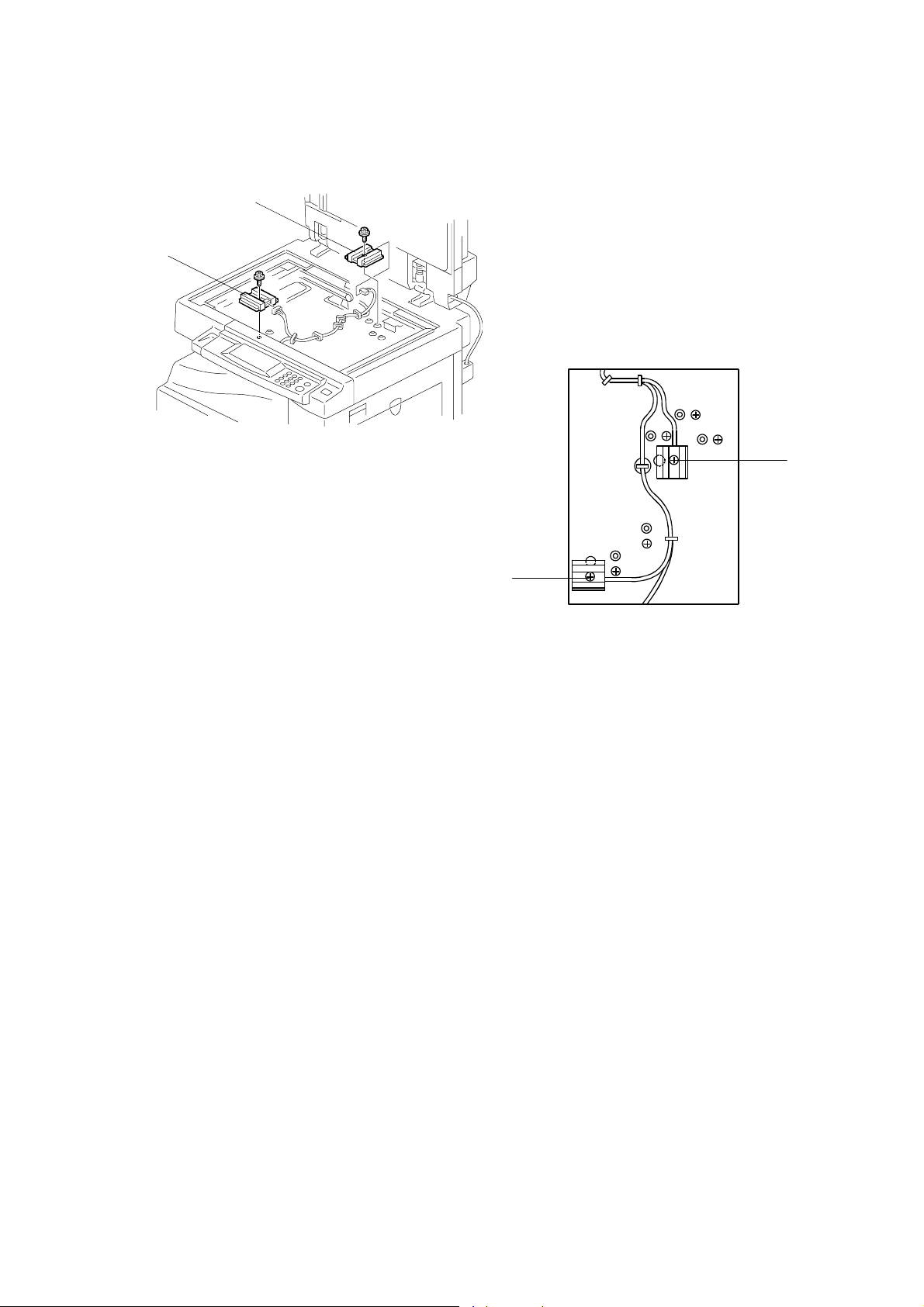
SCANNER SECTION
Procedure
[B]
[A]
B039R004.WMF
[D]
[C]
B039R012.WMF
1. Set the machine to detect 8K/16K originals as follows.
• If the machine is equipped with the platen cover: Access SP mode 5-955-1,
and set the setting to 1 (=Yes). The machine will now detect 8K/16K rather
than B4/B5. (B4-SEF → 8K-SEF; B5-SEF → 16K-SEF; B5-LEF → 16K-LEF)
• If the machine is equipped with the ADF or ARDF: Access SP mode 5-955-2,
and set the setting to 1 (=Yes). The machine will now detect 8K/16K rather
than A3/A4/B4/B5. (A3-SEF/B4-SEF → 8K-SEF; B5-SEF/A4-SEF → 16KSEF; B5-LEF/A4-LEF → 16K-LEF)
• Note that making either of the above settings will disable use of SP mode 5-
911.
2. Turn off the power, and remove the exposure glass (☛ 3.4.1).
3. Remove APS sensors [A, B].
4. Remove screws [C, D] at the new mount positions.
5. Mount the original width sensor into the new position (from where you removed
screw [C]), and screw.
6. Mount the original length sensor into the new position (from where you
removed screw [D]), and screw it.
7. Screw screws back into their original holes.
B039/B040/B043 3-14 SM
Page 83

3.4.7 SCANNER MOTOR
1. Rear cover (☛ 3.3.1)
2. Right upper cover (☛ 3.3.6)
3. Rear scale and exposure glass (☛
3.4.1)
SCANNER SECTION
4. Operation panel (☛ 3.3.5)
[A]
5. Top rear cover (☛ 3.3.7)
6. Detach the belt [A].
7. Scanner motor [B] (! x 3, 1 spring,
" x 1)
NOTE: When reinstalling the motor:
Fit the belt on first, then set
the spring in place, and then
screw in evenly, rotating from
screw to screw so that the
spring tension is correctly distributed.
After installing the motor, do the copy ad justments (☛ 3.13).
3.4.8 SCANNER H.P. SENSOR
1. Left upper cover (☛ 3.3.4)
2. Top rear cover (☛ 3.3.7)
3. Exposure glass (☛ 3.4.1)
NOTE: If the machine is an A(R)DF
model, remove both the DF
exposure glass and the exposure
glass.
[D]
[E]
[F]
[B]
B039R008.WMF
[C]
Adjustment
Replacement
4. Disconnect the scanner H.P. sensor
connector [C].
5. Scanner left lid [D] (! x 7)
6. Remove the sensor tape [E].
7. Scanner H.P. sensor [F]
B039R005.WMF
SM 3-15 B039/B040/B043
Page 84

SCANNER SECTION
3.4.9 ADJUSTMENT OF 2ND SCANNER POSITION
Do this procedure after replacing a scanner belt. If you replaced the second
scanner belts, go onto the next section (‘Adjustment of 1st and 2nd Scanner
Alignment’.)
[A]
[C]
[B]
[C]
[B]
B039R011.WMF
1. Remove the A(R)DF or platen cover.
2. Remove the operation panel (☛ 3.3.5).
3. Remove the top rear cover (☛ 3.3.7).
4. Loosen the 2 screws [A] holding the 2nd scanner belt in place.
5. Slide the 2nd scanner so that the second hole from the right on each scanner
arm is roughly aligned with the position guide holes [B] on the upper and lower
mainframe rims.
6. Insert the positioning tools [C] into both sets of holes.
NOTE: If the 1st scanner is preventing the pins from fitting in smoothly, loosen
the 1st scanner securing screws and slide the 1st scanner out of the
way (☛ 3.4.10, step 1).
7. Re-tighten the screws loosened in step 1 [A] and remove the positioning tools.
8. Go on to the next section, ‘Adjustment of 1st and 2nd Scanner Alignment’.
B039/B040/B043 3-16 SM
Page 85

SCANNER SECTION
3.4.10 ADJUSTMENT OF 1ST AND 2ND SCANNER ALIGNMENT
For how to use this procedure, see the previous section, ‘Adjustment of 2nd
Scanner Position’.
[C]
[C]
[B]
[D]
[A]
B039R007.WMF
[B]
[A]
Adjustment
Replacement
1. Remove the A(R)DF or platen cover.
2. Remove the operation panel (☛ 3.3.5).
3. Remove the top rear cover (☛ 3.3.7).
4. Loosen the 2 screws [A] holding the 1st and 2nd scanner belts in place.
5. Slide the 1st and 2nd scanners so that all three of the following are aligned on
both sides:
• The second hole from the right on each 2nd scanner arm
• The position guide holes on the upper and lower mainframe rims
• The 1st scanner position guide hole [B]
6. Insert the positioning tools [C] into both sets of holes.
7. Make sure that both the 1st and 2nd scanner belts are properly set in place on
both sides [D].
8. Re-tighten the screws loosened in step 1 [A] to clamp the scanner belts in
place, then remove the positioning tools.
SM 3-17 B039/B040/B043
Page 86

LASER UNIT
3.5 LASER UNIT
!
WARNING
Laser beam can seriously damage your eyes. Be absolutely sure that the
main power switch is off and that the machine is unplugged before
accessing the laser unit.
3.5.1 LOCATION OF “CAUTION” DECAL
B039R110.WMF
B039RLW.WMF
B039/B040/B043 3-18 SM
Page 87

3.5.2 TONER SHIELD GLASS
LASER UNIT
1. Open the front door.
2. Lift the toner cartridge latch [A].
3. Press the toner shield glass cover [B]
to the left and pull it out.
4. Pull out the toner shield glass [C].
[B]
3.5.3 LASER UNIT
1. Toner shield glass. (☛ 3.5.2)
2. Copy tray (☛ 3.3.3)
[E]
[C]
[A]
B039R151.WMF
Adjustment
Replacement
3. Pull out the (upper) paper tray.
4. Front long cover (☛ 3.3.9)
5. Disconnect the harness [D, E].
6. Laser unit [F] (! x 4)
NOTE: The screw at the left front
position [G] is longer than the
others.
[D]
[G]
[F]
B039R153.WMF
SM 3-19 B039/B040/B043
Page 88

LASER UNIT
3.5.4 LD UNIT
1. Laser unit (☛ 3.5.3)
2. LD unit [A] (! x 1)
NOTE: Do not screw the LD unit in too
tightly when installing it.
3.5.5 POLYGONAL MIRROR MOTOR
1. Laser unit (☛ 3.5.3)
2. Two rubber bushings [B]
3. Laser unit cover [C] (! x 1)
4. Polygonal mirror motor [D] (! x 4)
5. Do the copy adjustments (☛ 3.13).
[D]
[A]
B039R155.WMF
[C]
[B]
B039/B040/B043 3-20 SM
B039R154.WMF
Page 89

LASER UNIT
3.5.6 LASER UNIT ALIGNMENT ADJUSTMENT
!
WARNING
Be absolutely sure to reinstall the copy exit tray before making printouts.
The laser beam can seriously damage your eyes.
[A]
[B]
[D][C]
B039R156.WMF
Adjustment
Replacement
Turning the lever
counter-clockwise
alters the trim pattern
as shown above
Turning clockwise
alters the trim pattern
as shown above
B039R890.WMF
1. Use SP5-902 to output a trim pattern (pattern 10). If the pattern is not even,
adjust the alignment as follows.
2. Copy tray (☛ 3.3.3)
3. Loosen the four screws securing the laser unit (☛ 3.5.3).
4. If this is the first time this adjustment is being made: Remove the adjustment-
lever screw [A] (securing the adjustment lever [B]) from its factory set position
at [C], and loosely screw it in at the center of the long hole [D].
NOTE: If you have already adjusted the alignment at least once, the screw will
already be in the long hole. If readjustment is necessary, just loosen
the screw and continue as follows.
5. Rotate the lever clockwise or counterclockwise. This allows you to shift the
corners of the pattern ±0.4 mm with respect to the leading and trailing edges of
the paper. Using trial and error, adjust until the trim pattern is even.
6. Tighten screw [A] at its new position.
7. Tighten the other three screws.
8. Reinstall the copy tray.
9. Print the trim pattern and check the result. If further adjustment is required,
repeat this procedure.
SM 3-21 B039/B040/B043
Page 90

PCU SECTION
3.6 PCU SECTION
3.6.1 PCU
1. Toner bottle holder (☛ 1.2.3, step 2)
2. Open the right door.
3. Press in on the latch, and pull out the PCU. (☛ 1.2.3, step 3)
NOTE: Do not touch the OPC drum surface with bare hands.
4. Load new developer. (☛ 3.6.7)
5. After reinstalling, run SP2-214 to reinitialize the TD sensor.
6. Do steps 1 to 6 of the procedure in section 3.6.8.
3.6.2 PICK-OFF PAWLS
1. Take out the PCU (☛ 3.6.1)
or open the right door.
2. Pull each pawl [A] out from
the bottom.
3. Do the procedure in section
3.6.8.
[A]
[B]
B039R205.WMF
3.6.3 TONER DENSITY SENSOR
1. PCU (☛ 3.6.1)
2. The toner density sensor [B] is taped to the bottom of the PCU. Pry it off with a
regular screwdriver (! x 1).
NOTE: Do not turn the PCU upside down, as doing so will cause toner and
developer to spill out.
4. Do the procedure in section 3.6.8.
B039/B040/B043 3-22 SM
Page 91

3.6.4 OPC DRUM
[E]
[A]
B039R201.WMF
[C]
[B]
[D]
[G]
PCU SECTION
Adjustment
Replacement
[F]
B039R206.WMF
1. PCU (☛ 3.6.1)
2. Remove the front side piece [A] (! x 1) and rear side piece [B] (! x 2,
1 coupling), and separate the PCU top part (drum section) [C] from its bottom
part (developer section) [D]. Carry out the remaining steps on the drum section.
NOTE: To ensure that the left-side gears line up, be sure that the drum cover
[E] is closed when reinserting the front side piece.
3. Pry out the drum retaining clip [F].
NOTE: Be sure to reinstall the clip in the same orientation (with the lip facing
away from the drum shaft).
4. Pull out the front end of the OPC drum [G], and remove.
5. Do the procedure in section 3.6.8.
SM 3-23 B039/B040/B043
Page 92

PCU SECTION
3.6.5 CHARGE ROLLER AND CLEANING BRUSH
[E]
[D]
[B]
[A]
[C]
B039R204.WMF
1. OPC Drum (☛ 3.6.4)
2. Remove holding pin [A] and 1 stepped screw [B].
3. Turn the gear [C] as necessary so that the rear end piece can come out.
4. Pull out the charge roller [D] and cleaning brush [E] as a single assembly
(together with the plastic end pieces and springs).
5. Do the procedure in section 3.6.8.
3.6.6 CLEANING BLADE
1. Drum charge roller (☛ 3.6.5)
2. Cleaning blade [F] (! x 2)
[F]
3. Do the procedure in section 3.6.8.
B039R207.WMF
B039/B040/B043 3-24 SM
Page 93

3.6.7 DEVELOPER
[A]
PCU SECTION
[B]
[D]
[E]
[F]
B039R202.WMF
B039R203.WMF
1. PCU (☛ 3.6.1)
2. Tap the top of the PCU with a screwdriver at eight evenly spaced locations (two
or three taps at each spot) so as knock the recycled toner down into the
development section.
3. Set the PCU back into the mainframe.
4. Turn the main power on. Then open and close the door and wait for the
machine to rotate the development roller for 10 seconds. Then open and close
the door two more times, so that total rotation time is 30 seconds.
[C]
Adjustment
Replacement
5. Remove the PCU again.
6. Separate the developer section from the OPC drum section (☛ 3.6.4, step 2).
7. Remove the top part [A] of the development unit (! x 5), then place your finger
under the front-side flap [B] and push out so that the flap pops off the peg .
8. Set the coupling [C] back onto the shaft, tilt the development roller [D] upward
as shown, and turn the coupling (and shaft) in the direction of the arrow [E] to
remove developer from the roller.
9. Turn the bottom part [F] of the developer unit over and rotate the gears to
remove the developer.
10. Load new developer. (☛ 1.2.3, step 5)
11. After reinstalling, run SP2-214 to reinitialize the TD sensor.
NOTE: 1) Be sure that there is no toner or developer stuck on any of the gears.
(Clean as necessary with a blower brush, etc.)
2) Be sure to replace the Mylar at the rear side in the correct position. (The
Mylar protects the gears at the rea r side from falling toner).
SM 3-25 B039/B040/B043
Page 94

PCU SECTION
3.6.8 AFTER REPLACEMENT OR ADJUSTMENT
IMPORTANT: After replacing or adjusting any of the PCU components, please do
the following procedure.
1. Take 5 sample copies.
2. If black dots (dropped toner) appear on any of the copies, continue as follows.
(If all copies are clean, you don't need to carry out the following steps.)
3. Remove the PCU from the mainframe.
4. Tap the top of the PCU with a screwdriver at eight evenly spaced locations (two
or three taps at each spot), to knock the recycled toner down into the
development section.
5. Put the PCU back into the mainframe.
6. Turn the main power on. Then open and close the door and wait for the
machine to rotate the development roller for 10 seconds. Then open and close
the door two more times, so that total rotation time is 30 seconds.
7. Make some sky-shot copies (or solid black prints).
• If using A4/8
• If using A3/11" x 17" paper, make 2 copies/prints.
• To make solid black prints, use SP5-902 pattern 8.
NOTE: Step 7 is required only after parts replacement or adjustment. There is
no need to make sky-shot (or solid black) copies after replacing the
developer.
" x 11" paper, make 4 copies/prints.
1/2
B039/B040/B043 3-26 SM
Page 95

3.7 TONER SUPPLY MOTOR
1. Copy tray (☛ 3.3.3)
2. Open the front door.
3. Toner bottle holder (☛ 1.1.3, step 2)
4. Toner supply motor [A] (" x 1)
TONER SUPPLY MOTOR
[A]
B039R917.WMF
Adjustment
Replacement
SM 3-27 B039/B040/B043
Page 96

PAPER FEED SECTION
3.8 PAPER FEED SECTION
3.8.1 PAPER FEED ROLLER
1. Pull out the appropriate paper tray.
2. Clip [A]
3. Push the shaft back through the opening,
and tilt it up.
NOTE: If the black plastic bushing [B]
comes off, be sure to remount it
when reinstalling the shaft.
4. Paper feed roller [C]
[C]
[A]
[B]
B039R702.WMF
3.8.2 FRICTION PAD
1. Pull the appropriate paper cassette out.
2. Clip [D]
3. Push the shaft back through the
opening, so that the roller moves clear
of the friction pad.
4. Friction pad [E]
3.8.3 PAPER END SENSOR
1. Pull the appropriate paper cassette out.
2. Paper end sensor [F] (" x 1)
[E]
[D]
B039R703.WMF
[F]
B039R705.WMF
B039/B040/B043 3-28 SM
Page 97

3.8.4 EXIT SENSOR
Non-duplex Models
PAPER FEED SECTION
1. Open the right door.
2. Front right cover (☛ 3.3.10)
3. Guide [A] (! x 2)
4. Exit sensor [B] (" x 1)
Duplex Models
1. Open the right door.
[D]
[A]
[B]
B039R601.WMF
Adjustment
Replacement
2. Front right cover (☛ 3.3.10)
3. Lower guide [C] (! x 2)
4. Upper guide [D] (! x 2)
5. Exit sensor [E] (" x 1)
[E]
[C]
B039R945.WMF
SM 3-29 B039/B040/B043
Page 98

PAPER FEED SECTION
3.8.5 BY-PASS FEED ROLLER AND BY-PASS PAPER END
SENSOR
[A]
[B]
[C]
B039R804.WMF
1. By-pass tray (☛ 3.3.13)
NOTE: If you wish, you can just detach the tray and rest it on the ground
without disconnecting the connector (but be careful to avoid placing too
much load on the wires).
2. Sensor holder [A].
3. By-pass paper end sensor [B] (" x 1)
4. By-pass feed roller [C]
B039/B040/B043 3-30 SM
Page 99

3.8.6 REGISTRATION ROLLER
[D]
PAPER FEED SECTION
[B]
[E]
[F]
B039R951.WMF
[G]
[H]
[A]
[C]
Adjustment
Replacement
B039R950.WMF
1. PCU (☛ 3.6.1)
2. Front long cover (☛ 3.3.9)
3. Right door (☛ 3.3.12)
4. Rear cover (☛ 3.3.1)
5. High-voltage power supply (☛ 3.12.2)
6. Registration clutch (☛ 3.8.8)
7. Unhook the springs [A] and [B] at the rear and front sides.
8. Guide [C] (! x 1, " x 1)
9. Bushing [D] (# x 1)
10. Gear [E] and bushing [F] (# x 1)
11. Registration roller [G] with the image transfer unit [H]
SM 3-31 B039/B040/B043
Page 100

PAPER FEED SECTION
3.8.7 BY-PASS PAPER SIZE SENSOR
1. By-pass tray (☛ 3.3.13)
2. Tray lever [A] (# x 1, 1 pin)
3. Lift the upper tray [B]
4. By-pass paper size sensor [C]
(! x 1)
NOTE: When reinstalling the
sensor: Move the paper
guides to their middle
position (about halfway
between fully open and fully
closed), and install the round
gear so that the hole in the
gear [D] aligns with the peg
[E] on the sliding gear.
3.8.8 REGISTRATION CLUTCH
[E]
[D]
[C]
[A]
[B]
B039R704.WMF
[F]
B039R909.WMF
[G]
B039R911.WMF
1. Rear Cover (☛ 3.3.1)
2. Bracket holding the high-voltage power supply board [F] (! x 5, all connectors)
3. Registration clutch [G] (# x 1, " x 1)
B039/B040/B043 3-32 SM
 Loading...