

Page 1

COMPACT DISC Recordable/ReWritable
Auto Changer DRIVE
MC104S
SPECIFICATIONS
(Preliminary)
RICOH Company, Ltd.
Dec. 22, 1999
Page 2

NOTICE
This equipment has been tested and found to comply with the limits for a Class B digital
device , pursuant to part 15 of the FCC Rules. These limits are designed to provide
reasonable protection against harmful interference in a residential installation. This
equipment generates , uses and can radiate radio frequency energy and , if not installed
and used in accordance with the instructions , may cause harmful interference to radio
communication.
However , there is no guarantee that interference will not occur in a particular installation.
If this equipment does cause harmful interference to radio or television reception , which
can be determined by turning the equipment off and on , the user is encouraged to try to
correct the interference by one or more of the following measures :
---Reorient or relocate the receiving antenna.
---Increase the separation between the equipment and receiver.
---Connect the equipment into an outlet on a circuit different from that to which the
receiver is connected.
---Consult the dealer or an experienced radio / TV technician for help.
FCC WARNING
Changes or modification not expressly approved by the party responsible for compliance
could void the user's authority to operate the equipment.
CAUTION
Use of controls or adjustments or performance of procedures other than those specified
herein may result in hazardous radiation exposure.
a) Pay careful attention not to let the invisible laser beam emitted from the optical pickup
enter into your eyes.
b) When you find a troubled state of the component in the optical pickup containing the
laser diode , change to the specified new optical pickup. Do not open the optical pickup
housings.
Page 3
Akustischer Geräuschpegel
Dieser Drucker überschreitet einen Geräuschpegel von 70 dB (A) während dem Betrieb
nicht.
Declaration of Conformity
“The Product complies with the requirements of the EMC Directive 89/336/EEC
and the Low Voltage Directive 73/23/EEC.”
Page 4

Revision History
No. Revised Data Revision Contents Description Page
1 Dec. 22, 1999 Preliminary
Page 5

MC104S SPECIFICATIONS
CONTENTS
I. OUTLINE----------------------------------------------------------------------------------------------
1. Overview ......................................................................................................I - 1
2. Features.......................................................................................................I - 1
II. CONSTRUCTION AND INSTALLATION-----------------------------------------------------
1. Basic Construction........................................................................................II - 1
2. Connector.....................................................................................................II - 3
III. SPECIFICATIONS---------------------------------------------------------------------------------
1. Functionality............................................................................................... III - 1
2. Basic Specification.....................................................................................III - 2
3. Audio Specification.....................................................................................III - 3
4. Performance Specification .........................................................................III - 3
5. Condition for use and Safety standard.......................................................III - 3
6. Reliability and Usable Life..........................................................................III - 6
7. Safety Standards........................................................................................III - 6
8. Appearance................................................................................................III - 7
9. Storage Conditions.....................................................................................III - 8
10. Magazine....................................................................................................III - 12
11. Disc ............................................................................................................III - 14
12. SCSI Command..........................................................................................III - 15
(Dec. 22 , 1999) i (Preliminary)
Page 6

MC104S SPECIFICATIONS
FIGURE
II - 1. Compact Disc Rewritable Auto Changer Drive configuration...............II - 1
II - 2. Inside...................................................................................................II - 2
II - 3. Magazine.............................................................................................II - 2
II - 4. Front....................................................................................................II - 3
II - 5. Back.....................................................................................................II - 3
II - 6. Device Configration Jumper ................................................................II - 5
III - 1. Installation Conditioins.........................................................................III - 5
III - 2. CD-R/RW Drive Dimension..................................................................III - 7
III - 3. Packing Arrangement (1).....................................................................III - 9
III - 4. Packing Arrangement (2).....................................................................III - 10
III - 5. Transport Mode ...................................................................................III - 11
III - 6. How to eject/insert a CD from/in the magazine....................................III - 12
III - 7. How to insert the magazine.................................................................III - 13
III - 8. How to eject the magazine ..................................................................III - 13
TABLE
II - 1. Function of the jumper connector........................................................II - 5
II - 2. SCSI ID................................................................................................II - 5
III - 1. SCSI Command...................................................................................III - 15
(Dec. 22 , 1999) ii (Preliminary)
Page 7

I. OUTLINE
1. Overview
The Compact Disc Recordable/ReWritable Auto Changer drive MC104S can do much
more than read and write the usual CD-R discs. When you load it with a rewritable
CD-RW disc, you can record, read, and edit any kind of data, because these discs
allow you to rewrite information that has already been recorded.
2. Features
MC104S SPECIFICATIONS
1) Running OPC*1 gives a flatter writing signal that improves reliability.
2) An improved anti-heat design means that no cooling fan is needed.
3) Uses the world standard SCSI interface.
4) Can read not only CD-R and CD-RW discs, but also video CDs, music CDs,
and photo CDs.
5) Half-height space but a great capacity.
6) Conforms to the world standard Orange Book Part II (CD-R) and Part III (CDRW). Can use “TRACK AT ONCE”, “DISC AT ONCE”, “MULTISESSION”,
“PACKET WRITE” and “SESSION AT ONCE”.
7) Supports packet write for easy writing to CD-R and CD-RW discs.
*1 Continuously monitors the signal level during recording and adjusts the laser
power to compensate when the disc is dirty, insuring a flat signal.
(Dec. 22 , 1999) I - 1 (Preliminary)
Page 8
MC104S SPECIFICATIONS
BUTTON
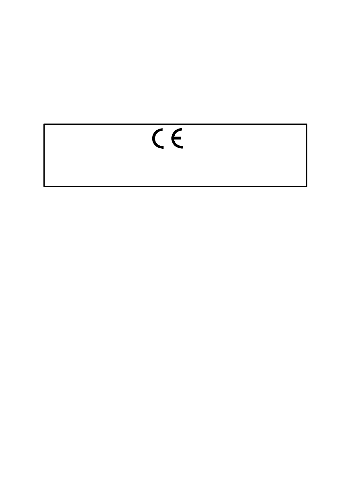
II. CONSTRUCTION AND INSTALLATION
1. Basic Construction
The Compact Disc Recorder / Rewriter Auto Changer Drive: MC104S consists of
following parts.
The Compact Disc Recorder / Rewriter Auto Changer Drive’s configuration and
Connector are shown below;
DOOR
HEAD
PHONE
JACK
VIBRATION
VOLUME
LED
EJECT
FACE
ISOLATOR
Fig. II - 1 Compact Disc Rewritable Auto Changer Drive configuration
(Dec. 22, 1999) II - 1 (Prelininary)
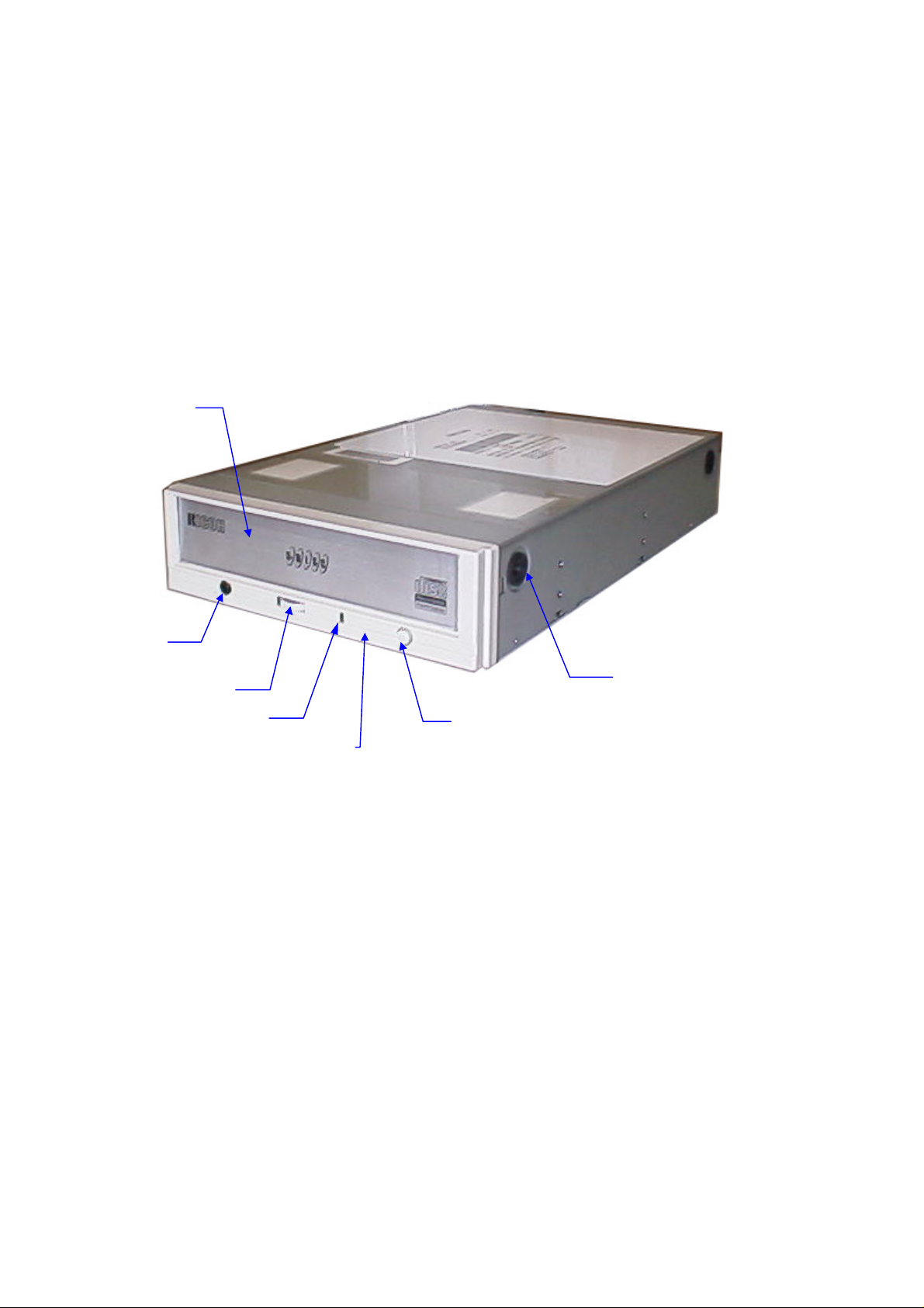
Page 9
PICKUP
UNIT
CHASSIS
MAGAZINE
HOUSE
MC104S SPECIFICATIONS
MAIN PCB
Fig. II - 2 Inside
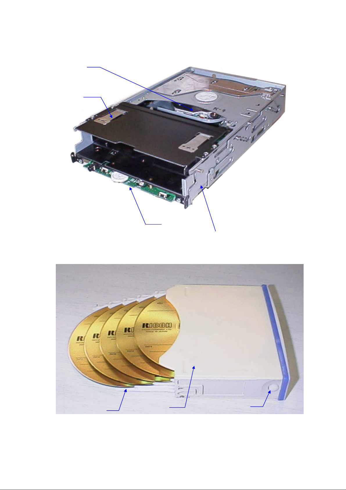
TRAY
CASE
UNLOCK BUTTON
Fig. II - 3 Magazine
(Dec. 22, 1999) II - 2 (Prelininary)
Page 10

MC104S SPECIFICATIONS
2. Connector
The Connectors are located as shown below. The function of each parts are also
described below.
Door
Headphone Jack
Fig. II - 4 Front
Analog Audio Output Connector
Busy LED
Volumie Control
Eject Button
Jumper Connector
SCSI Connector
Power Connector
Fig. II - 5 Rear
(Dec. 22, 1999) II - 3 (Prelininary)
Page 11

MC104S SPECIFICATIONS
2.1. Door
This is the door to insert the magazine. Place discs on disc trays of the magazine,
then insert the magazine and the CDs will be loaded. The system need to be
installed the driver to load discs on disc trays of the magazine. The only lowest
disc in the magazine is loaded if the driver would not be installed.
! - Don’t use force to pull out or push in the magazine. This might cause
damage to the loading section of the drive.
2.2. Eject Button
This is the button used to eject or bring in the disc tray.
2.3. Busy indicator
This indicator light shines green when power is on. When the disc tray or disc is
being accessed, the light shines or flashes orange. Even when a disc is loaded
or a disc is not being accessed, the light shines green. When a illegal disc is
loaded or some hardware trouble occurs, the indicator blinks.
2.4. Headphone Jack
This jack is for connecting headphones or mini-speakers.
2.5. Volume control
This is used to adjust the output volume of the headphone jack. It can’t be used
to adjust the output volume for the audio output connectors on the rear panel.
2.6. Power Connector
Used to connect to the host computer’s power supply (DC 5V / 12V)
! - Be careful not to reverse the poser connector when attaching it. A reversed
connection may cause damage to the equipment (not covered by the
warranty).
2.7. SCSI Connector
Use a 50 pin double-end flat SCSI cable to connect to the SCSI interface.
! - Connecting or disconnecting connectors while power is on may result in a
short circuit, causing damage to the equipment. When connecting or
disconnecting connectors, make sure to turn off the power beforehand.
2.8. Analog Audio Output Connector
Used to connect to the sound card.
2.9. Jumper Connector
Used when selecting the SCSI ID number and terminator. SCSI ID and terminator
changes become valid after power is turned off, then on again.
! - If two peripheral devices use the same SCSI ID number, it will cause the
host computer to operate abnormally or fail to start up.
(Dec. 22, 1999) II - 4 (Prelininary)
Page 12

MC104S SPECIFICATIONS
2
1
0
SCSI ID
246
8
135
7
PWB
Terminator
Fig. II - 6 Jumper Connector
Table II - 1 Jumper Connector Setting
Jumper pin Function Factory setting
1 – 2 SCSI ID (2) 0 (OFF/Open)
3 – 4 SCSI ID (1) 0 (OFF/Open)
5 – 6 SCSI ID (0) 0 (OFF/Open)
7 – 8 Terminator 1 (ON/Short)
No. 1 - 2, 3 - 4, 5 - 6 : SCSI ID
Table II−2 SCSI ID
SCSI ID Pin No. 2 Pin No.3 Pin No.4 Remark
0 OFF OFF OFF Factory setting
1 OFF OFF ON
2 OFF ON OFF
3 OFF ON ON
4 ON OFF OFF
5 ON OFF ON
6 ON ON OFF
7 ON ON ON *1
Note:ON : Jumper Pin is attached
OFF : Jumper Pin is not attached
*1: Don’t use this setting. It is located as the setting for SCSI Adapter Card
usually.
No. 7 - 8 : Terminator
When no other SCSI peripheral devices besides the CD-R/RW drive are
connected to the host computer, a terminator must be attached to the drive. Also,
when multiple peripheral devices are connected, this drive needs a terminator if it
is the last in the line.
The terminator of this product can be set by installing (terminator: ON) or removing
(terminator: OFF) the jumper pin from the jumper connector.
(Dec. 22, 1999) II - 5 (Prelininary)
Page 13

III. SPECIFICATIONS
1. Functionality
1.1. Recording
Data should be recorded on the optical disc in response to host computer
command.
1) Drive receives necessary information such as logical block address, number of
block and data to be recorded from the host computer.
2) Recording to pre-recorded area can not be executed. (CD-R disc)
3) Overwriting to pre-recorded area can be executed. (CD-RW disc)
1.2. Reading
Data on optical disc should be read in response to the host computer command.
Audio playing (CD-DA) can be executed when receiving the Audio playing
command from the host computer.
MC104S SPECIFICATIONS
1.3. Load / Eject of Disc
1) Load
Place discs on disc trays of the magazine, then insert the magazine and the CDs
will be loaded. The system need to be installed the driver to load discs on disc
trays of the magazine. The only lowest disc in the magazine is loaded if the
driver would not be installed.
2) Eject
Operator can eject the magazine (discs) by pushing this button.
1.4. Spindle Motor Start / Stop
The controller of the drive senses the disc to be set on the turn-table connected
with the spindle motor and then starts to rotate the spindle motor, in response to
the host computer command
1.5. Seek Motor
The controller of the drive starts to move the optical pick up carriage, in response
to the host computer command.
1.7. Eject Button
Operator can eject the magazine (discs) by pushing this button.
1.8. Busy indicator
This indicator light shines green when power is on. When the disc tray or disc is
being accessed, the light shines or flashes orange. Even when a disc is loaded
or a disc is not being accessed, the light shines green. When a illegal disc is
loaded or some hardware trouble occurs, the indicator blinks.
(Dec. 22, 1999) III - 1 (Preliminary)
Page 14

MC104S SPECIFICATIONS
2. Basic Specification
Type : Tray Type
Supported Function (Write / Read / Play)
Write Read Play*1
CD-DA
CD-ROM
CD-Extra
CD-ROM XA
Photo CD *2
CD-I *2
CD-G *3
CD-Text
ü ü ü
ü ü
ü ü ü
ü ü
ü ü
ü ü
ü ü
ü ü
*1): Play means Audio play back. Read means
Data Transfer.
*2): CD-I, Photo-CD requires special reader/player.
Photo-CD writing requires Kodak license.
*3): RAW Sub-channel Data
Writing Mode : Track at Onse
Disk at Onse
Multisession
Packet Write
Read Error Rate : 10
Write Error Rate : 10
-12
Bits or less
-10
Bits or less
Recording Capacity :
CD-R disc 700/650/550MByte (Type80/74/63)
CD-RW disc 700/650MByte (Type80/74)
Controller :
Host I/F SCSI II (Small Computer System Interface II)
Data Transfer speed Max.5 MB/sec.(Async), 8 MB/sec.(Sync)
Buffer Memory : 2 Mbytes
(Dec. 22, 1999) III - 2 (Preliminary)
Page 15

MC104S SPECIFICATIONS
3. Audio Specification
Audio output :
Line Output Level 0.70 V ± 0.1 V rms
(output resistance: 100kΩ, 1kHz)
S/N = over 83dB, distortion rate = less than 0.05%
Headphone Output Level 0.48 V ± 0.1 V rms
(output resistance: 100kΩ, 1kHz)
4. Performance Specification
Rotation Speed : 1x, 2x, 4x, 6x, 8x : CLV
8x - 20x : Full CAV
Write/Read Speed (Ave.): 20x : 3.00 MB/sec. (Mode1, Mode2, Form1)
20x : 3.40 MB/sec. (Mode2, Form2)
20x : 3.45 MB/sec. (CD-DA)
*1
8x : 1,200 KB/sec. (Mode1, Mode2, Form1)
8x : 1,362 KB/sec. (Mode2, Form2)
6x : 900 KB/sec. (Mode1, Mode2, Form1)
6x : 1,021 KB/sec. (Mode2, Form2)
*1
*1
*1
*1
6x : 1,034 KB/sec. (CD-DA)
4x : 600 KB/sec. (Mode1, Mode2, Form1)
4x : 681 KB/sec. (Mode2, Form2)
4x : 689 KB/sec. (CD-DA)
2x : 300 KB/sec. (Mode1, Mode2, Form1)
2x : 342 KB/sec. (Mode2, Form2)
2x : 345 KB/sec. (CD-DA)
1x : 150 KB/sec. (Mode1, Mode2, Form1)
1x : 170 KB/sec. (Mode2, From2)
1x : 172 KB/sec. (CD-DA)
*1
Reading only
Access Time : 120msec. or less
Initial Time : CD-ROM : less than 14 seconds
CD-R, CD-RW : less than 19 seccons
(including blank disc)
*1
*1
Changing Disc Time : Less than 5 seconds
(except spining down and mounting time)
Loading/Unloading Disc Tray Time : Less than 2 seconds
(except spining down and mounting time)
Magazine
Loading Time : Less than 5 seconds
(until chacking from setting the magazine)
*except mounting time
Ejecting Time : Less than 4 seconds
(until ejecting from pushing the eject button)
(Dec. 22, 1999) III - 3 (Preliminary)
Page 16

MC104S SPECIFICATIONS
*except spinning down time
Acoustic Noise :
Idle 40 dB or less (Sound Power Level)
Operating 55 dB or less (Sound Power Level)
Non-Operating 49 dB or less (Sound Pressure Level)
5. Condition for use and Safety standard
5.1. Power Supply :
5V Power Supply :
Voltage DC5V ± 5%
Ripple 50mVp-p or less
Current 2.0A (Typ.), 3.0A or less (peak)
12V Power Supply :
Voltage DC12V ± 10%
Ripple 100mVp-p or less
Current 0.7A (Typ.), 1.5A or less (peak)
Power Consumption : 15W or less (Normal Operation)
8W or less (Stand by)
5.2. Environment Conditions
Temperature :
Operating 5 - 40 °C(Without Fan)
Non-Operating -30 - 65 °C (Power OFF, Without the magazine)
Humidity :
Operating 5 - 90 %(No Condensation)
Non-Operating 5 - 95 %(No Condensation)
(Power OFF, Without the magazine)
Temperature Gradient : 20 °C /hour(Max.)
Humidity Gradient : 10 %/hour(Max.)
Wet-Bulb Gradient : 30 °C (Max.)
Vibration :
Operating 0.035mm p-p (10 - 45Hz)
0.025mm p-p (45 - 65Hz)
0.2 x 9.8 m/s2 (0.2G) (65 - 150Hz)
Non-Operating 1 x 9.8 m/s2 (1.0G) (5 - 300Hz)
(Power OFF, Without the magazine)
Shock :
Operating 1 x 9.8 m/s2 (1.0G) or less (6msec. Half Sine)
Non-Operating 40 x 9.8 m/s2 (40G) or less (11msec. Half Sine)
(Power OFF, Without the magazine)
Altitude :
Operating -305 - 3,048 m
(Dec. 22, 1999) III - 4 (Preliminary)
Page 17

MC104S SPECIFICATIONS
Magnetic Condition : 4,000 A/m (50 Oe) or less
Dust : Class 3,000,000 or less (Typ.)
Illuminance : 3,000 Lux or less
Against Electrostatic Stress :
Contact discharge : Over 6kV
Air discharge : Over 12kV
Installation Conditions :
Mounting direction Horizontal/Vertical
(Eject Button must be right side.)
Installation Angle 15° or less
Horizontal
Fig. III - 1 Installation Condition
(Dec. 22, 1999) III - 5 (Preliminary)
Page 18

MC104S SPECIFICATIONS
6. Reliability and Usable Life
MTBF : 30,000 hours
MTTR : 30 min.
Equipment Life : 3 Years
Loading/Unloading
the magazine cycle : 5,000 times
Loading/Unloading
the disc tray cycle : 50,000 times (drive)
10,000 times (disc tray)
Seek endurance : Over 100,000 times
Duty :
POH 40 hours/week, 50 weeks/year, 3 years
Active 20%
Write/Active 50%
Load/Eject the magazine 5 times/day
Load/eject the disc tray 25 times/day (drive)
5 times/day (disc tray)
Error rate :
Unrecoverable Errors Once per 1012 bits or less
7. Safety Standards
Application Standard : UL,cUL,TUV,CE,CDRH
Radio Interference : Vcci-ClassB , FCC-ClassB , EN55022-ClassB
(Dec. 22, 1999) III - 6 (Preliminary)
Page 19

MC104S SPECIFICATIONS
8. Appearance
Dimensions : 146 mm x 233 mm x 41.3 mm
(Width) (Depth) (Height)
Weight : 1.5 kg or less
Volumecontrol
26.4
12.5
Door
Headphone
jack
7.3
LED
Load/Eject button
6.6
13.0 0.6
16.4
43.440.1
148.0
Fig. III - 2 CD-R/RW Drive Dimension
(Dec. 22, 1999) III - 7 (Preliminary)
Page 20

9. Storage Conditions
9.1. Storage Conditions
Temperature : -30 - 65 °C (Max.)
Humidity : 5 - 95 % (No Condensation)
Temperature Gradient : 20 °C /Hour (Max.)
Humidity Gradient : 10 %/Hour (Max.)
Wet-Bulb Gradient : 30 °C (No Condensation)
Vibration : 1.0 x 9.8 m/s2 (1.0 G) or less (5 - 300 Hz)
Shock : 40 x 9.8 m/s2 (40.0 G) or less (11 msec. Halfsine)
MC104S SPECIFICATIONS
Drop : 60.0 cm (JIS Z0202)
Altitude : -305 - 15,240 m
Illuminance : 3,000 Lux or less
Preservation term : 1 year or less
9.2. Transportation Condition
Container : Cardboard Packing Case
Means of Transportation : Mixed loading possible
Stacking Layers : 6 or less (6 units package)
9 or less (1 unit package)
Attached Articles : Caution and the magazine
(Dec. 22, 1999) III - 8 (Preliminary)
Page 21

MC104S SPECIFICATIONS
9.2. Storage Conditions
1) 1 unit package
Fig. III - 3 Packing Arrangement 1)
1 unit package
Size : 278mm x 224mm x 195mm
Weight : 3.0kg
6 units package
Size : 695mm x 572mm x 215mm
Weight : 19.8kg
(W) (L) (H)
(W) (L) (H)
(Dec. 22, 1999) III - 9 (Preliminary)
Page 22

2) 6 units package
MC104S SPECIFICATIONS
Fig. III - 4 Packing Arrangement 2)
Size : 435mm x 280 mm x 350 mm
(W) (L) (H)
Weight : 10.7kg
(Dec. 22, 1999) III - 10 (Preliminary)
Page 23

MC104S SPECIFICATIONS
9.3. Set/Release the transport mode
Set the transport mode when transporting as follows;
1. Tutn on the drive unit and take out the magazine.
2. Push the eject button five seconds or more, and the busy LED light turns orange and
the drive works, and then confirm the busy LED light turns green.
3. Turn off the drive unit. Do not turn on the drive unit during transportation. Follow
above procedure again in case of turning on.
4. Turn on the drive unit to release the transport mode.
Fig. III - 5 Transport Mode
(Dec. 22, 1999) III - 11 (Preliminary)
Page 24

MC104S SPECIFICATIONS
10. Magazine
10.1 How to eject/insert CDs from/in the magazine
1. While pushing the unlock button on the side of the magazine, pull out a claw of
a disc tray and pull out the disc tray.
2. Place a disc in the hollow of the disc tray keeping the label side of the disc
upper to prevent a touch on the recording side. Do not place over two discs on
one disc tray.
3. Put the disc tray back to the magazine along by rails in the magazine slowly.
Put the disc tray back for certain.
4. Insert five discs or less taking above procedure over again.
! - Don’t use cleaning discs on the market.
- Insert five disc trays in case there are some empty disc trays.
Fig. III - 6 How to eject/insert CDs from/in the magazine
(Dec. 22, 1999) III - 12 (Preliminary)
Page 25

MC104S SPECIFICATIONS
10.2 How to insert/eject the magazine
Insert
1. Insert the magazine straight into the drive unit from the door in the front of the
drive. Follow mentioned on the outside of the magazine.
2. Push the magazine straight in until locking.
Fig. III -7 How to insert the magazine
Eject
1. Push the eject button on the Face.
Fig. III -8 How to eject the magazine
(Dec. 22, 1999) III - 13 (Preliminary)
Page 26

MC104S SPECIFICATIONS
11. Disc
Dimensions :
Outside Diameter φ 120 ± 0.3 mm
Inside Diameter φ 15 +0.1/-0.0 mm
Thickness 1.2 +0.3/-0.1 mm
Recording area (User area) : φ 50 - 116 mm
Recording capacity :
Media Type Type63 Type74 Type80
CD-R 550 MB 650 MB 700 MB
CD-RW ------ 650 MB 700 MB
Track pitch : 1.6 ± 0.1 µm
Recording material :
CD-R Organic pigment (phthalocyanine)
/ Au or Ag lamination (Organic protective layer attached)
CD-RW Ag-In-Sb-Te phase change recording material
Substrate material : PC ( Polycarbonate)
Reflectance :
CD-R 65 % or more
CD-RW 15 - 20%
Eccentricity : 70 µm or less
Maximum camber angle : 0.4° or less
Recommend recording power :
CD-R 6 - 7mW (atλ=785nm, NA=0.5)
CD-RW 8 - 14mW (atλ=785nm, NA=0.5)
Playback power : 1mW or less
Playback stability :
CD-R 106 times or more (0.7mW)
CD-RW 106 times or more (1.0mW)
Storage life :
CD-R 10 years or more
(
5 - 25°C, 5 - 60%RH, Avoiding direct sunlight
CD-RW 30yeares or more (
5 - 25°C, 5 - 60%RH)
)
Environment for use :
CD-R -5 - 55 °C , 5 - 95 %RH
CD-RW 10 - 40 °C , 10 - 80 %RH
(Dec. 22, 1999) III - 14 (Preliminary)
Page 27

MC104S SPECIFICATIONS
12. SCSI Command
SCSI command supported by MC104S are shown below.
Table III - 1 Group 0 Command
Operation Code Type Command Name
00H
01H
03H
04H
08H
0AH
0BH
12H
15H
16H
17H
1AH
1BH
1DH
1EH
M
O
M
O
O
O
O
M
O
M
M
O
M
M
O
Test Unit Ready
Rezero Unit
Request Sense
Format Unit
Read (6)
Write (6)
Seek (6)
Inquiry
Mode Select (6)
Reserve
Release (6)
Mode Sense (6)
Start/Stop Unit
Send Diagnostic
Prevent/Allow Medium Removal
Table III - 2 Group 1 Command
Operation Code Type Command Name
25H
28H
2AH
2BH
2FH
35H
3BH
3CH
O:Option、V:Vendor Unique、M:Mandatory、R:Reserved
M
M
M
O
O
M
O
O
Read CD Recoeded Capacity
Read (10)
Write (10)
Seek (10)
Verify (10)
Synchronize Cache
Write Buffer
Read Buffer
(Dec. 22, 1999) III - 15 (Preliminary)
Page 28

MC104S SPECIFICATIONS
Table III - 3 Group 2 Command
Operation Code Type Command Name
42H
43H
43H
44H
45H
47H
48H
4AH
4BH
4EH
51H
52H
53H
54H
55H
5AH
5BH
5CH
5DH
O
O
O
O
O
O
O
R
O
V
V
V
V
V
M
M
V
V
R
Read Sub-Channel
Read TOC/PMA/ATIP
Read TOC (Old Version)
Read Header
Play Audio (10)
Play Audio MSF
Play Audio Track/Index
Get Event Status Notification
Pause/Resume
Stop Play/Scan CD-ROM
Read Disc Information
Read Track Information
Reserve Track
Send OPC Information
Mode Select (10)
Mode Sense (10)
Close Track/Session
Read Buffer Capacity
Send Cue Sheet
Table III - 4 Group 5 Command
Operation Code Type Command Name
A1H
A5H
A8H
A6H
AAH
B9H
BAH
BBH
BDH
BEH
V
O
O
M
R
V
O
V
V
V
Blank
Play Audio (12)
Read (12)
Load/Unload CD
Write (12)
Read CD MSF
Scan
Set CD Speed
Mechanism Status
Read CD
Table III - 5 Group 6 Command
Operation Code Type Command Name
D8H
D9H
V
V
Read CD-DA
Read CD-DA MSF
Table III - 6 Group 7 Command
Operation Code Type Command Name
EFH V Eject Check
O:Option、V:Vendor Unique、M:Mandatory、R:Reserved
(Dec. 22, 1999) III - 16 (Preliminary)
Page 29

RICOH COMPANY , LTD.
3-2-3 , Shin-Yokohama
Kohoku-ku , Yokohama
222-8530 Japan
TEL 045-477-1660
FAX 045-477-1807
 Loading...