

Page 1

RICOH
FACSIMILE
RICOH
FAX
1000L
FIELD SERVICE MANUAL
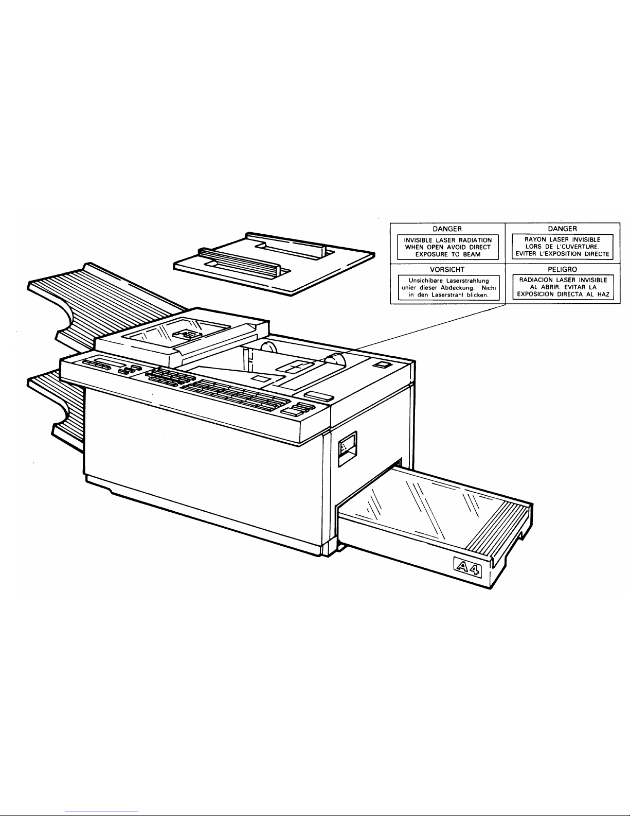
WARNING
RICOH FAX 1000L CONTAINS A LASER BEAM GENERATOR.
LASER BEAMS CAN CAUSE PERMANENT EYE DAMAGE.
DO NOT OPEN THE LASER DIODE OR LOOK ALONG THE
LASER BEAM PATH WHILE THE MAIN POWER IS ON.
Page 2
Page 3

TABLE OF CONTENTS
SECTION 1 FEATURES AND SPECIFICATIONS
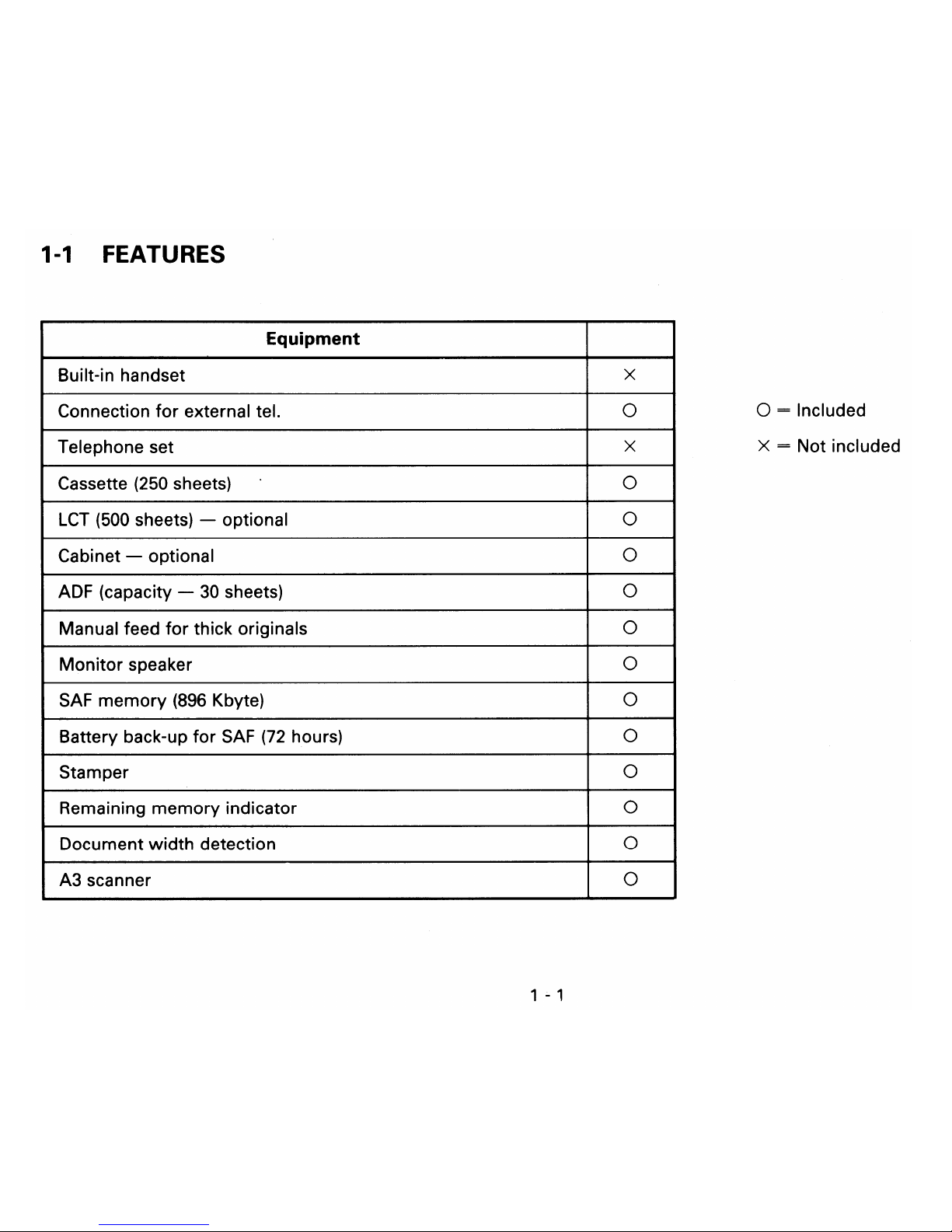
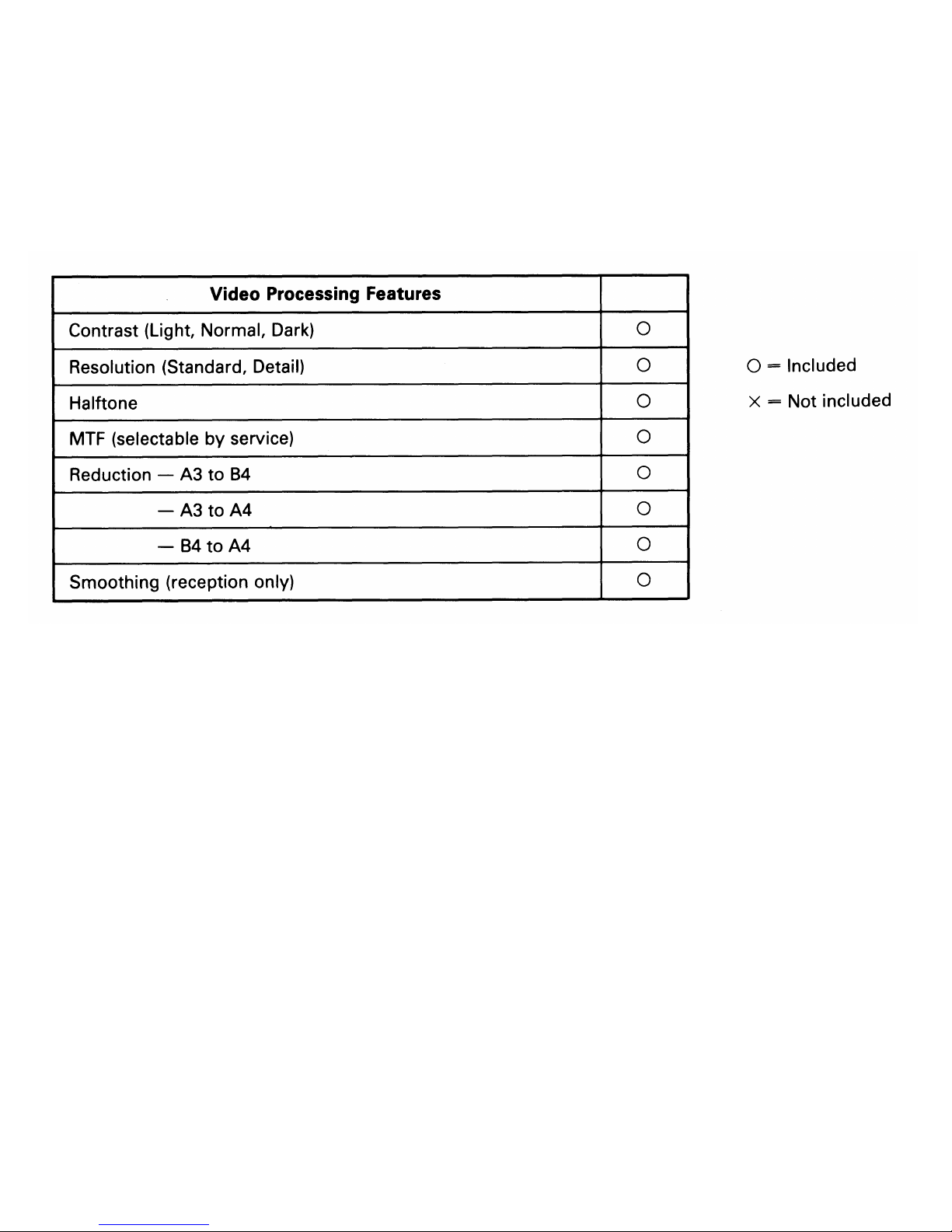
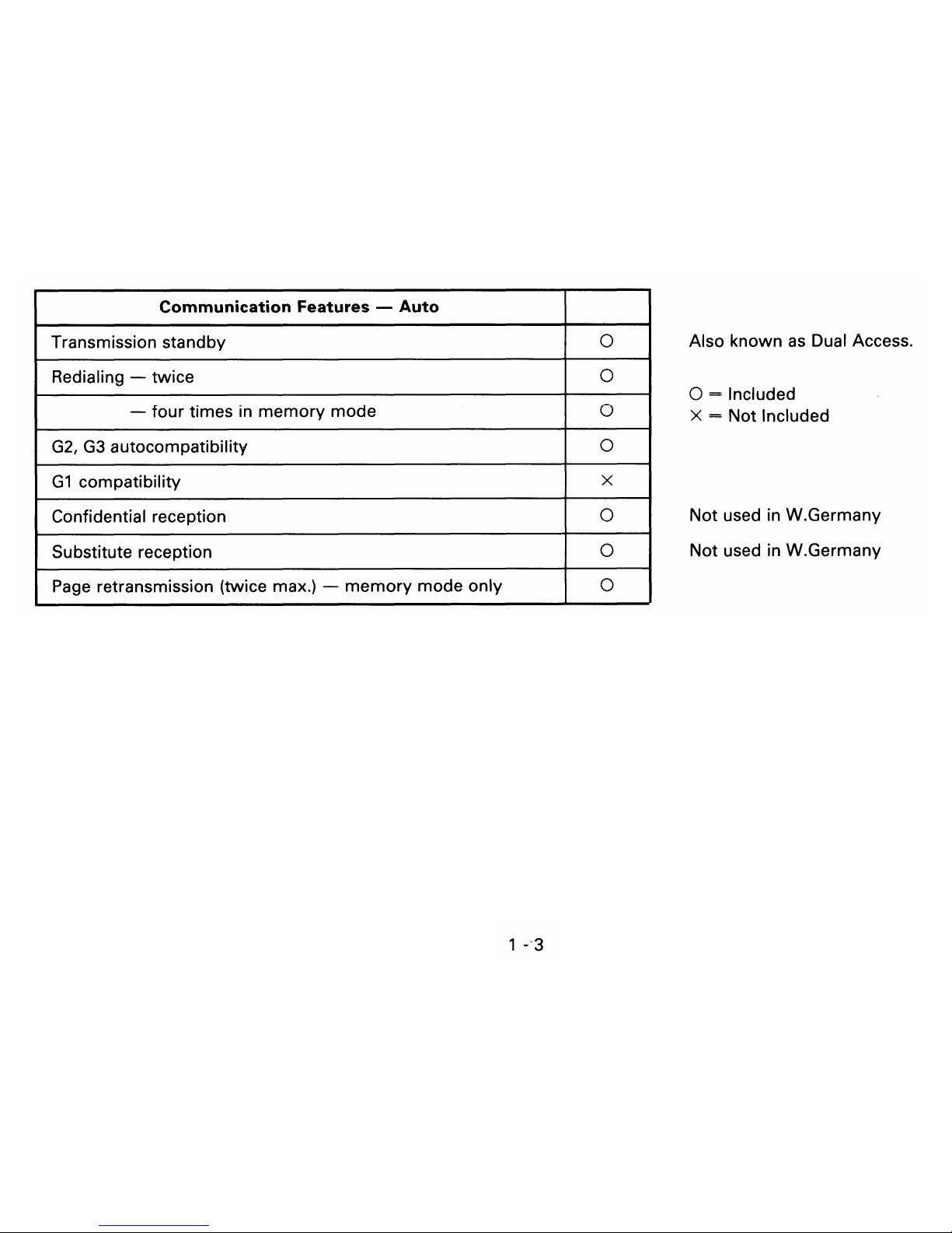
1-1 Features
. . . . . . . . . . . . . . . . . . . . . . . . . . . . . . . . . . . . . . . . . . . . . . . . . . . . . . . . . . . . .
1- 1
1-2 Specifications
. . . . . . . . . . . . . . . . . . . . . . . . . . . . . . . . . . . . . . . . . . . . . . . . . . . . .
1-15
SECTION 2 UNPACKING
2-1 Installation Requirements
. . . . . . . . . . . . . . . . . . . . . . . . . . . . . . . . . .
2- 1
2-2 Unpacking Procedure
. . . . . . . . . . . . . . . . . . . . . . . . . . . . . . . . . . . . . . . .
2- 2
2-3 Accessories
Check Li~t
. . . . . . . . . . . . . . . . . . . . . . . . . . . . . . . . . . . . . .
2- 3
SECTION 31NSTALLATION
3-1 Assembly
. . . . . . . . . . . . . . . . . . . . . . . . . . . . . . . . . . . . . . . . . . . . . . . . . . . . . . . . . . .
3- 1
3-2 Power Connection
. . . . . . . . . . . . . . . . . . . . . . . . . . . . . . . . . . . . . . . . . . . . . .
3- 6
3-3 Master Belt Rotation Counter Initializing
. . . . . . . . . . .
3- 7
3-4 Sub-documentTable
. . . . . . . . . . . . . . . . . . . . . . . . . . . . . . . . . . . . . . . . .
3- 8
3-5 Cleaning
Padlnstallation
. . . . . . . . . . . . . . . . . . . . . . . . . . . . . . . . . . .
3- 8
3-6 Filling the Stamp
. . . . . . . . . . . . . . . . . . . . . . . . . . . . . . . . . . . . . . . . . . . . . . . .
3- 9
SECTION 4 COMPONENT GUIDE
4-1 External View
. . . . . . . . . . . . . . . . . . . . . . . . . . . . . . . . . . . . . . . . . . . . . . . . . . . . .
4- 1
4-2 Internal Components
. . . . . . . . . . . . . . . . . . . . . . . . . . . . . . . . . . . . . . . . .
4- 2
Drive Layout
. . . . . . . . . . . . . . . . . . . . . . . . . . . . . . . . . . . . . . . . . . . . . . . . . . . . . . .
4- 2
Mechanical Component Layout
. . . . . . . . . . . . . . . . . . . . . . . . .
4- 4
Electrical Component Layout
. . . . . . . . . . . . . . . . . . . . . . . . . . . . .
4- 8
SECTION 5 PROGRAMMING AND TESTING
5-1 Operation Panel
. . . . . . . . . . . . . . . . . . . . . . . . . . . . . . . . . . . . . . . . . . . . . . . . .
5- 1
5-2 User Level Programming
. . . . . . . . . . . . . . . . . . . . . . . . . . . . . . . . . . .
5- 5
5-3 Service Level
. . . . . . . . . . . . . . . . . . . . . . . . . . . . . . . . . . . . . . . . . . . . . . . . . . . . .
5-12
5-3-1
1.
2.
3.
5-3-2
1.
2.
3.
4.
5.
5-3-3
5-3-4
5-3-5
Service Functions
. . . . . . . . . . . . . . . . . . . . . . . . . . . . . . . . . .
Entering and Exiting Service Mode . . . . . . . .
Function Table
. . . . . . . . . . . . . . . . . . . . . . . . . . . . . . . . . . . . . . . .
Functions
. . . . . . . . . . . . . . . . . . . . . . . . . . . . . . . . . . . . . . . . . . . . . . . .
Bit Switch Programming
ROM and RAM Display, RAM Rewriting
System Report
ROM and RAM Printout
Error Code Display
Service Report
CC1l’Tand
Maker Codes
Service Station Telephone Number
Recovery from Printer System Crashes
NCU Parameter Programming
Test Mode
. . . . . . . . . . . . . . . . . . . . . . . . . . . . . . . . . . . . . . . . . . . . . .
Entering and Exiting Test Mode
. . . . . . . . . . . . .
Modem Test
. . . . . . . . . . . . . . . . . . . . . . . . . . . . . . . . . . . . . . . . . . . .
Operation Panel Test
. . . . . . . . . . . . . . . . . . . . . . . . . . . . . .
Fluorescent Lamp Lighting
. . . . . . . . . . . . . . . . . . . . .
Tone Test
. . . . . . . . . . . . . . . . . . . . . . . . . . . . . . . . . . . . . . . . . . . . . . . .
Printer Test
. . . . . . . . . . . . . . . . . . . . . . . . . . . . . . . . . . . . . . . . . . . .
Dedicated Transmission Parameter
Programming
. . . . . . . . . . . . . . . . . . . . . . . . . . . . . . . . . . . . .
Confidential File Printout . . . . . . . . . . . . . . . . . . . . . . .
5-12
5-12
5-13
5-14
5-25
5-25
5-26
5-27
5-28
5-28
5-30
5-31
5-34
5-4 Quality Checks
. . . . . . . . . . . . . . . . . . . . . . . . . . . . . . . . . . . . . . . . . . . . . . . . . . .
5-35
—l—
Page 4

SECTION 6 REMOVAL AND REPLACEMENT
6- 1
6- 2
6- 3
6- 4
6- 5
6- 6
6- 7
6- 8
6- 9
6-10
Cover Removal
. . . . . . . . . . . . . . . . . . . . . . . . . . . . . . . . . . . . . . . . . . . . . . . . . . .
6- 1
ADF and Scanner Components . . . . . . . . . . . . . . . 6- 5
Charge
. . . . . . . . . . . . . . . . . . . . . . . . . . . . . . . . . . . . . . . . . . . . . . . . . . . . . . . . . . . . .
6- 9
Exposure
. . . . . . . . . . . . . . . . . . . . . . . . . . . . . . . . . . . . . . . . . . . . . . . . . . . . . . . . . . . . . . .
6-10
Paper Feed
. . . . . . . . . . . . . . . . . . . . . . . . . . . . . . . . . . . . . . . . . . . . . . . . . . . . . . . . .
6-15
Development
. . . . . . . . . . . . . . . . . . . . . . . . . . . . . . . . . . . . . . . . . . . . . . . . . . . . . .
6-17
Transfer
. . . . . . . . . . . . . . . . . . . . . . . . . . . . . . . . . . . . . . . . . . . . . . . . . . . . . . . . . . . . . .
6-20
Fusing
. . . . . . . . . . . . . . . . . . . . . . . . . . . . . . . . . . . . . . . . . . . . . . . . . . . . . . . . . . . . . . . . .
6-22
Quenching
. . . . . . . . . . . . . . . . . . . . . . . . . . . . . . . . . . . . . . . . . . . . . . . . . . . . . . . . . .
6-28
PCBs
. . . . . . . . . . . . . . . . . . . . . . . . . . . . . . . . . . . . . . . . . . . . . . . . . . . . . . . . . . . . . . . . . . .
6-29
SECTION 7 ADJUSTMENTS
7-1 ADF
. . . . . . . . . . . . . . . . . . . . . . . . . . . . . . . . . . . . . . . . . . . . . . . . . . . . . . . . . . . . . . . . . . . . .
7- 1
7-2 Scanner
. . . . . . . . . . . . . . . . . . . . . . . . . . . . . . . . . . . . . . . . . . . . . . . . . . . . . . . . . . . . . .
7- 2
7-3 Printer
. . . . . . . . . . . . . . . . . . . . . . . . . . . . . . . . . . . . . . . . . . . . . . . . . . . . . . . . . . . . . . . . .
7- 7
7-4 VPU
. . . . . . . . . . . . . . . . . . . . . . . . . . . . . . . . . . . . . . . . . . . . . . . . . . . . . . . . . . . . . . . . . . . .
7-10
SECTION 8 MAINTENANCE
. . . . . . . . . . . . . . . . . . . . . . . . . . . . . . . . . . . . . .
8- 1
SECTION 9 TROUBLESHOOTING
9-1 Service Call Conditions
. . . . . . . . . . . . . . . . . . . . . . . . . . . . . . . . . . . . . .
9- 1
9-2 Copy Quality Problems
. . . . . . . . . . . . . . . . . . . . . . . . . . . . . . . . . . . . . .
9- 6
9-3 Mechanical Problems
. . . . . . . . . . . . . . . . . . . . . . . . . . . . . . . . . . . . . . . .
9-29
9-4 Error Codes
. . . . . . . . . . . . . . . . . . . . . . . . . . . . . . . . . . . . . . . . . . . . . . . . . . . . . . . .
9-40
APPENDIX
A. Bit Switches
B. Jumpers, Test Points, and VRs
C. Timing Charts
D. Sensor Table
E. Block Diagrams
F. Glossary
PAPER FEED UNIT TYPE 1000L
POINT-TO-POINT DIAGRAM
— 2 —
Page 5

SECTION 1
FEATURES AND SPECIFICATIONS
Page 6
Page 7
1 - 2
Page 8
Page 9
1 - 4
Page 10
1 - 5
Page 11
1 - 6
Page 12
Page 13
1 - 8
Page 14
1 - 9
Page 15
1 - 10
Page 16

1 - 11
Page 17
1 - 12
Page 18

1 - 13
Page 19
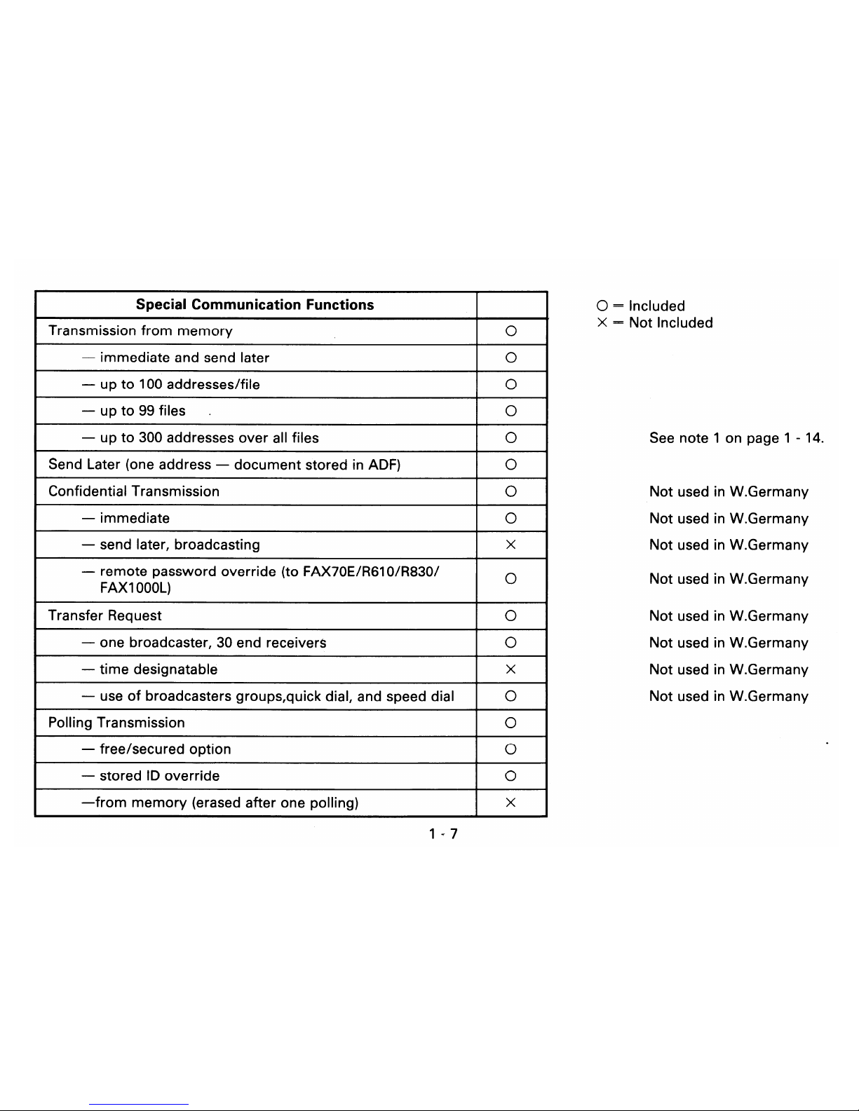
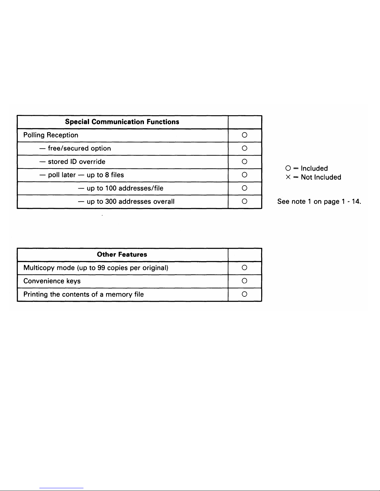
Note 1:
The total number of addresses stored in the machine for polling reception and memory transmission, when
added together, cannot exceed 300.
1 - 14
Page 20

1-2 SPECIFICATIONS
Type
Circuit
Connection
Document size
Document feed
ADF capacity
Scanning method
Scan resolution
SAF capacity
Compression
Modulation
Protocol
Desk-top transceiver
PSTN, PABX
Direct coupling
Length:
105 —
1200 mm
Up to 14 m available
Width:
148
— 301 mm
Thickness: 0.05
— 0.2 mm
Automatic feed, face down
Manual feed for thick documents
30 sheets
Flat bed with CCD
Main scan:
8 pixels/mm
Sub scan:
3.85 lines/mm (Standard)
7.7 lines/mm (Detail)
896 kbytes (about 49 CClTT #1 test charts at standard resolution)
MH, MR, EFC
QAM, PHM, AM-PM-VSB
Groups 2 and 3; automatic compatibility
1 - 15
Page 21

Data rate
Transmission time
Printing system
Paper size
Maximum printout width
Printer resolution
Power supply
Power consumption
(average)
Power consumption
(maximum)
Dimensions
Weight
9600/7200/4800/2400 bps
Automatic fallback
15 s for one CClTT #1 test chart using standard resolution, 9600 bps,
and EFC (no TTI, MTF, or ECM)
Laser printing, plain paper, dry toner
B4, A4
250 mm (B4)
Main scan:
16 dots/mm
Sub scan:
15.4 lines/mm
230 ± 30 Vac, 50 Hz, single phase
Standby:
30 w
Transmission:
60 W
Reception:
300 W (upper cassette)
310 W (lower cassette)
Copying:
360 W (upper cassette)
370 W (lower cassette)
520 W
435 x 550 x 295 mm (W x D x H)
Excluding trays, handset, and cabinet
About 28 kgs
Excluding trays, handset, and cabinet
1 - 16
Page 22

SECTION 2
UNPACKING
Page 23
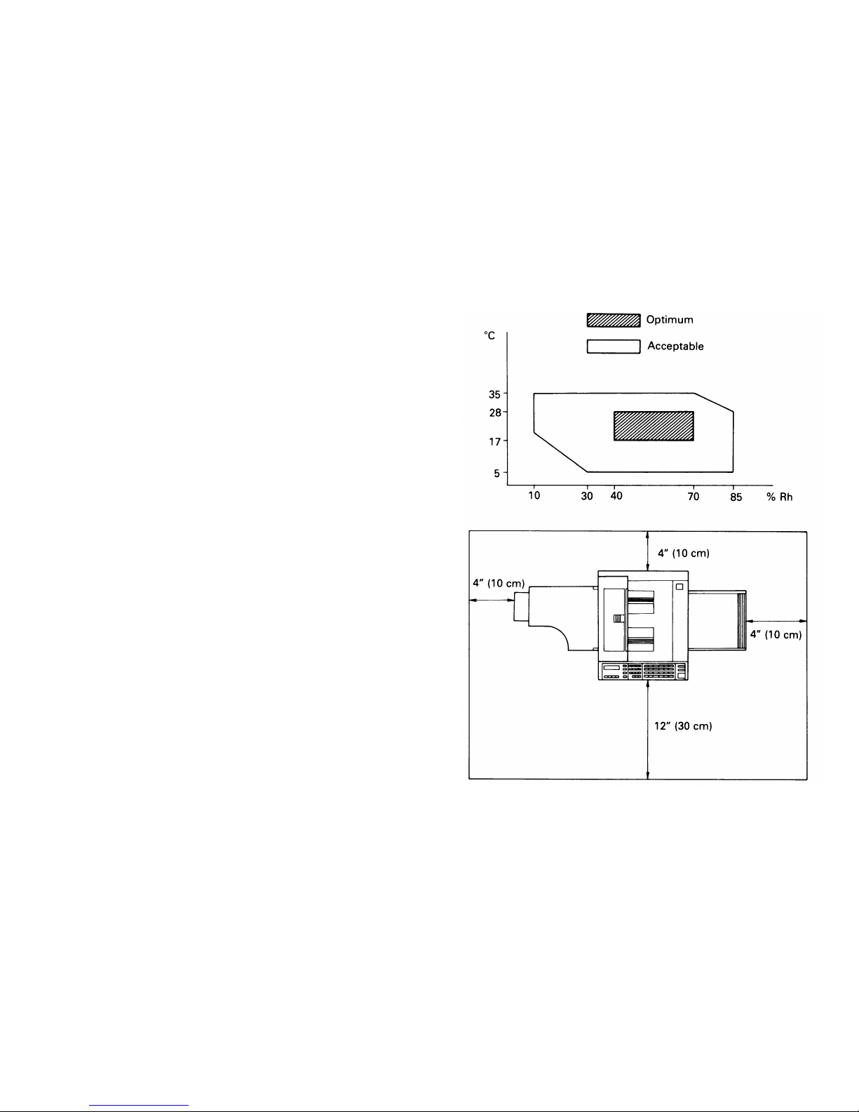
2-1 INSTALLATION REQUIREMENTS
Install in a place which satisfies the following conditions.
• Not exposed to direct sunlight.
• Away from areas containing corrosive gas.
• Well ventilated (air turnover at least three times per hour).
• Not subject to vibration.
• Ambient dust 0.15 mg/m
3
(4 X 10
–3
oz/yd3)
• Condensation-free
• Temperature 17 to 28°C (63 to 82° F)
• Humidity 40 to 70% RF (without condensation)
• Away from other electronic equipment, to avoid
interference.
• Away from heaters and air conditioners, to avoid sudden
changes of temperature.
• With clearance as shown to the right.
• On a strong and level base.
2 - 1
Page 24
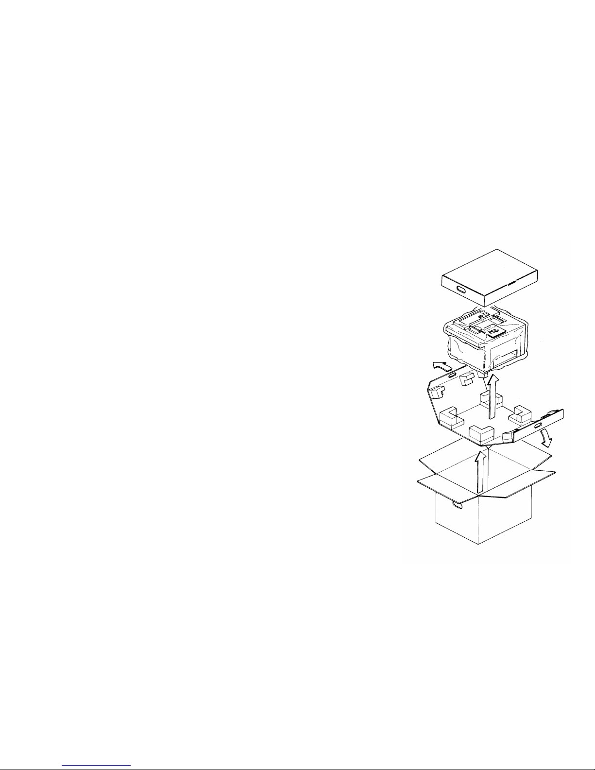
2-2 UNPACKING PROCEDURE
1. Take out the accessory box and the machine.
2. Open the vinyl envelope and take out the machine.
Caution: Put the machine on the optional table or a
table that is horizontally level within 2
degrees.
2 - 2
Page 25
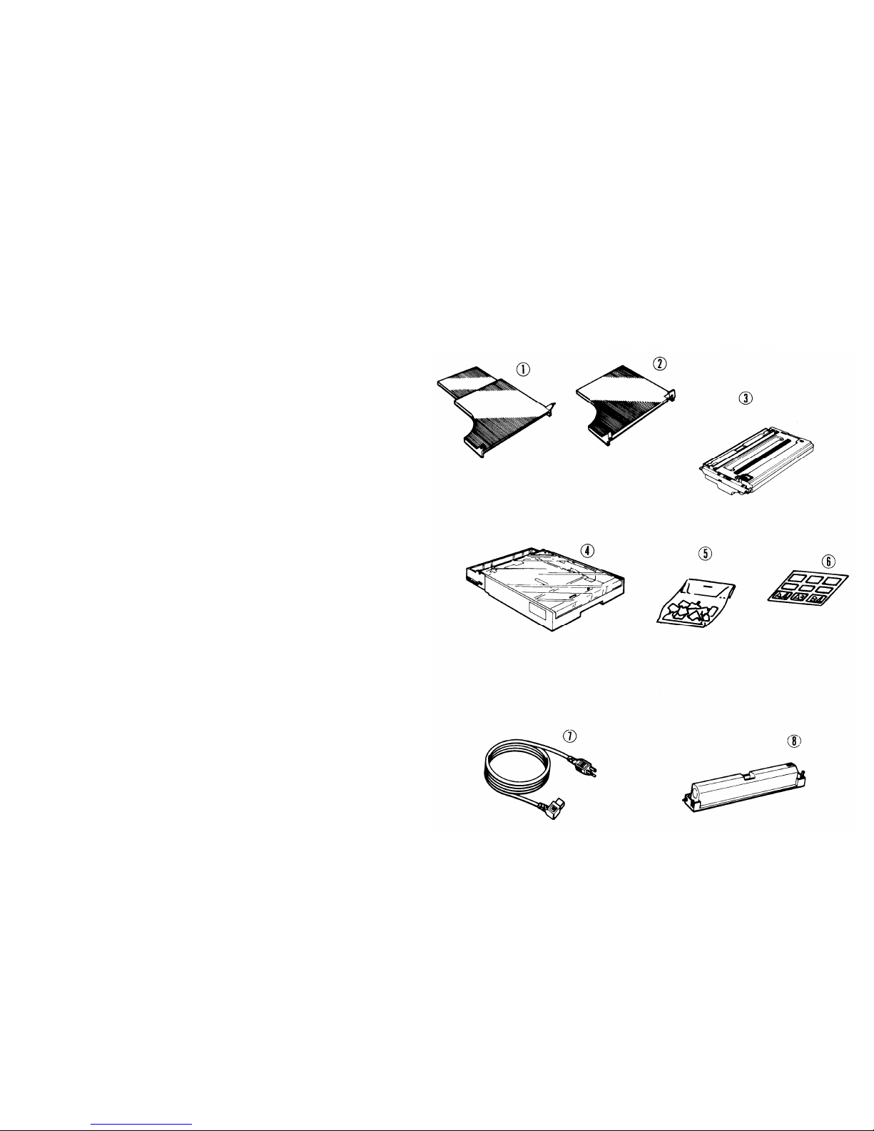
2-3 ACCESSORIES CHECK LIST
1. Open the accessory box and check the following
accessories.
1) Document Tray
(1 pc)
2) Copy Tray
(1 pc)
3) Master Unit
(1 pc)
4) Cassette
(1 pc)
5) Paper Size Actuators
(1 pc)
6) Paper Size Decals
(1 sheet)
7) Power Supply Cord
(1 pc)
8) Toner Cartridges
(2 pcs)
2 - 3
Page 26

9)
10)
11)
12)
13)
14)
15)
16)
17)
18)
19)
20)
Operators Manual
Speed Dial Label Cover
Refill Ink
Stamper Removal Tool
Sub-document Table
Paper
Vinyl Gloves
Plastic bag
Quick Dial Labels
Speed Dial Label
Cleaning Pad and Screws
Sub-document Table Bracket
(1 pc)
(1 pc)
(1 pc)
(1 pc)
(1 pc)
(1 pc)
(2 pcs)
(1 pc)
(2 pcs)
(1 pc)
(1 pc)
(1 pc)
2 - 4
Page 27

SECTION 3
INSTALLATION
Page 28
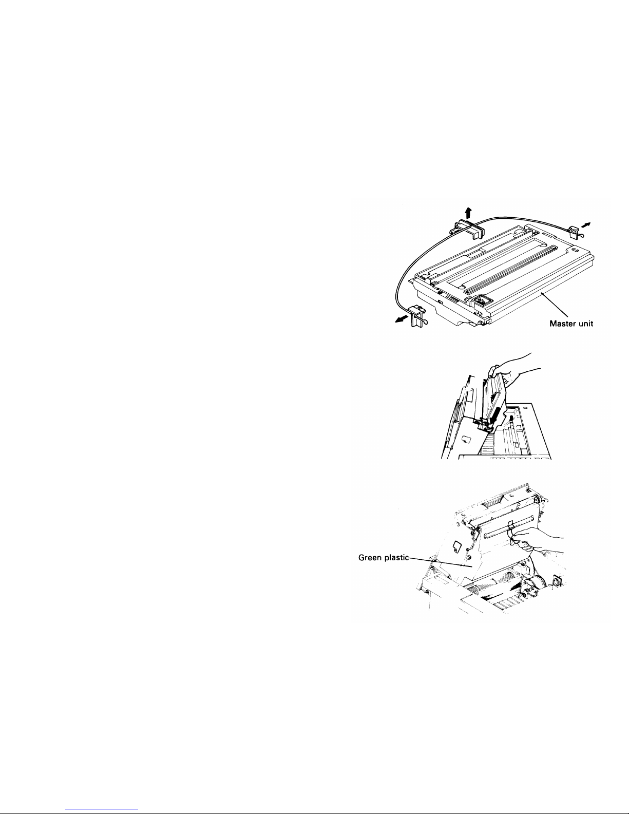
3-1 ASSEMBLY
1. Remove the three wedges from the master unit.
Caution:
Do not touch the master belt (purple material)
and avoid exposing it to light.
2. Open the upper unit and insert the master unit into the
machine along the guide until the unit stops.
3. Peel off the green plastic cover that protects the master.
4. Close the upper unit.
Caution:
The master belt counter should be reset.
(Please refer to page 3 - 7.)
3 - 1
Page 29
5. Open the right cover.
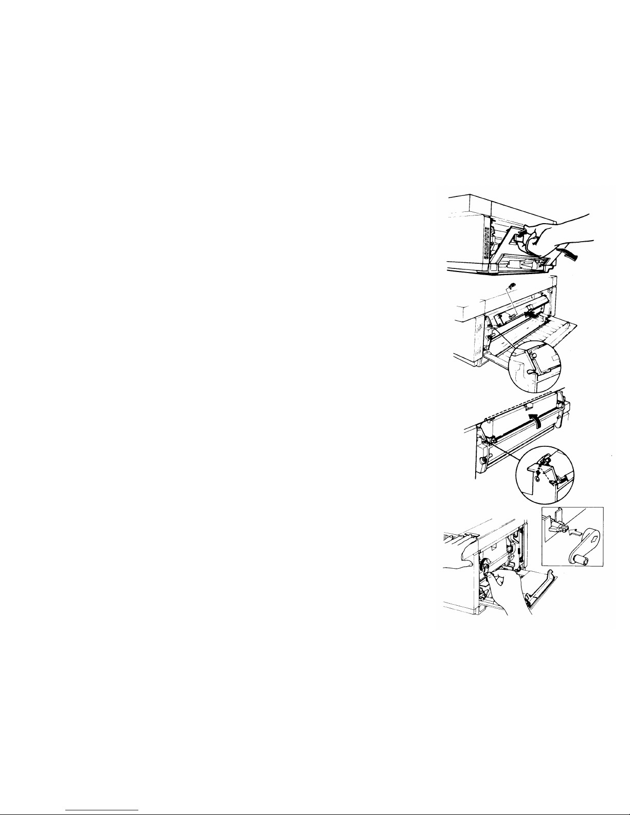
6. Shake a toner cartridge well.
7. Remove the cartridge crank from the cartridge.
8. Set the pins on the toner cartridge into the slots on the
development unit. Then rotate the cartridge upwards
until it snaps into place.
9. Install the cartridge crank on the shaft.
Then turn the crank clockwise to strip off the cartridge
seal. Remove the cartridge crank.
10. Remove the toner cartridge and install another toner
cartridge (refer to steps 6 to 9).
Note: When adding toner during normal operation,
only one cartridge should be replaced.
11. Close the right cover.
3 - 2
Page 30
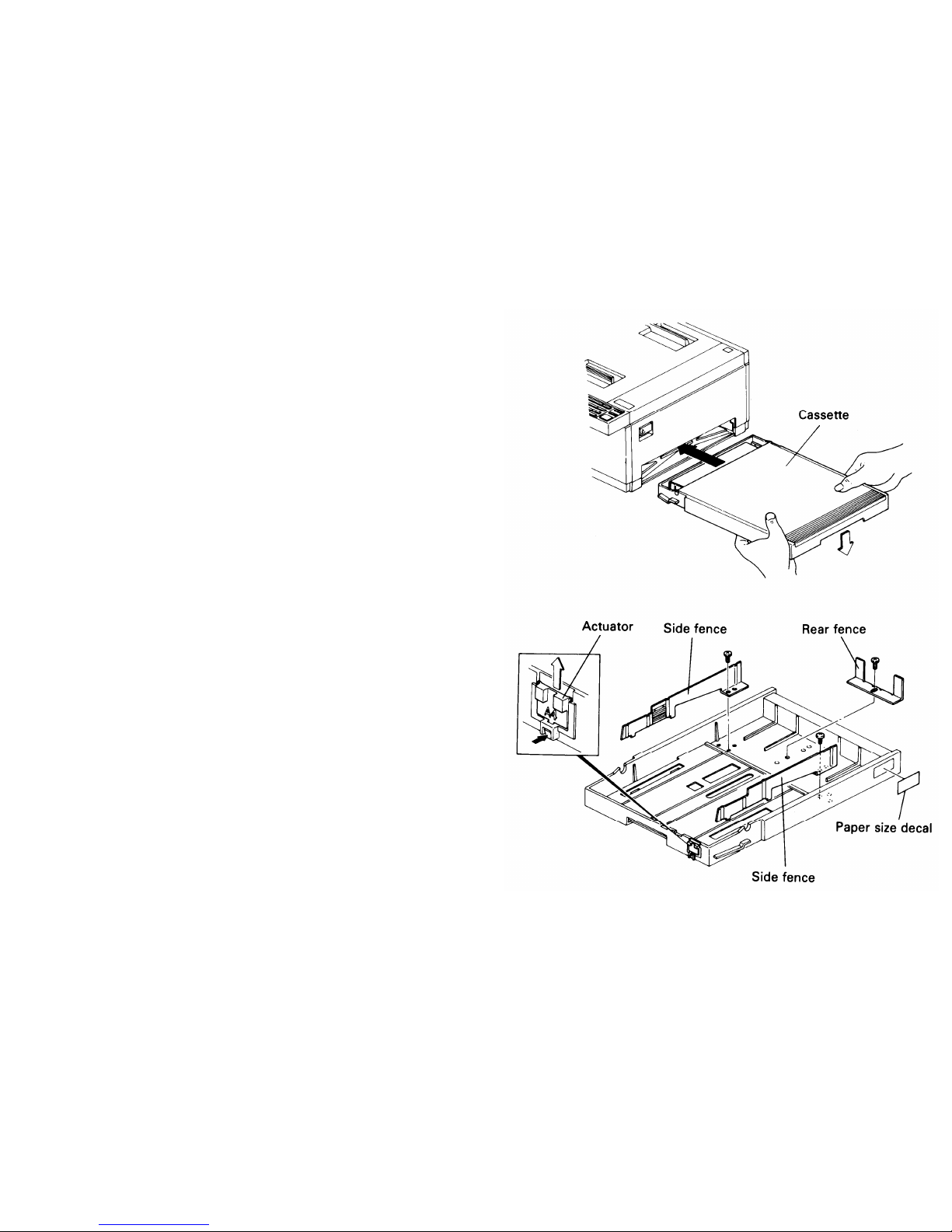
12. Install the cassette.
Note:
If the paper size which the customer will use is
different from the initial size, modify the
cassette as follows.
1) Move the rear and side fences to the appropriate
positions.
2) Attach the appropriate paper size decal to the tray.
3) Install the appropriate actuator.
4) Attach the top cover.
5) Add paper and install the tray.
3 - 3
Page 31

13. Quick Dial Labels
1) Remove the quick dial label cover.
2) Install the quick dial labels.
3) Replace the quick dial label cover.
3 - 4
Page 32

14. Speed Dial Label
1) Install the speed dial label.
2) Install the speed dial label cover.
15. Install the cleaning pad (see page 3-8).
16. Install the copy tray.
17. Install the document tray.
18. Put some ink in the stamper (see page 3-9).
3 - 5
Page 33

3-2 POWER CONNECTION
1.
2.
3.
4.
Connect the power cord to a 115V 50/60 Hz power source
(or 230V 50Hz depending on the model) capable of supplying more than 10A.
Wall voltage must not fluctuate more than 10%.
Make sure that the plug is firmly inserted into the outlet.
A dedicated circuit is recommended.
3 - 6
Page 34

3-3 MASTER BELT ROTATION COUNTER INITIALIZATION
When the master is installed at installation or when changing the master, the counter should be initialized, as follows.
1.
Turn on the main switch.
2. Press the Function key.
3. Enter 87 at the keypad.
4. Press the Yes key.
5. Press the Yes key again.
READY
100% 11 : 30
SET DOCUMENT
3 - 7
Page 35

3-4 SUB-DOCUMENT TABLE
If the sub-document table is needed, please install it as follows.
1. Take the tape off the adhesive strip on the sub-document
table bracket.
2. Attach the sub-document table bracket to the center of
the top cover.
Note: The top of the top cover must be flush with the
top of the sub-document table.
3. Attach the sub document table to the bracket.
3-5 CLEANING PAD INSTALLATION
1. Open the exit cover.
2. Attach the cleaning pad (4 screws).
3 - 8
Page 36

3-6
1.
2.
3.
4.
5.
FILLING THE STAMPER
Open the ADF cover.
Remove the stamper as follows with the tool provided in
the accessories box.
1)
2)
3)
Move the slotted end of the tool over the stamper.
Push down the tool until the hooks click into place
around the bottom of the stamper.
Lift out the tool and stamper.
Add a few drops of ink.
The inlet is in the bottom of the stamper.
The ink is provided in the accessories box.
Caution: The ink should not be taken internally.
Replace the stamper as follows.
1) Place the stamper in position manually.
2) Check that the stamper is in with the red end facing up.
Close the ADF cover.
3 - 9
Page 37

SECTION 4
COMPONENT GUIDE
Page 38

4-1 EXTERNAL VIEW
4 - 1
Page 39

4-2 INTERNAL COMPONENTS
1. Drive Layout
4 - 2
Page 40

No.
Name
No.
Name
1
R2 Idle Gear — 18T
20
Fan Drive Pulley —
Large/Main Drive Gear — Small
2
Reverse Idle Gear
21
Main Drive Pulley
3
ADF Idle Gear — T40
22
Tensioner Roller — T16
4
ADF Idle Gear — T45
23
Registration Clutch
5
ADF Idle Gear — T48
24 Registration Drive Pulley
6
ADF Clutch
25
Belt Pulley
7
R1 Gear 26
Feed Pulley
8
Belt Tensioner Idler
27
Development Clutch
9
R1 Pulley
28
Sleeve Gear
10
R2 Pulley
29
Idle Gear —
Toner Supply
11
Idler 2 — T14
30
Toner Supply Gear
12
Fan Drive Pulley — Medium
31
Agitator Idle Gear
13
Fan Drive Pulley — Small
32
Agitator Gear
14
Exit Gear — T18
33
Master Belt Rotation Gear — T20
15
Idle Gear — Z20
34
Master Drive Gear — T23
16 Fusing Unit Gear – T35
35
Master Drive Pulley — T20
17
Idle Gear — T33
36
Tensioner Pulley — Master Drive
18
Idle Gear — T44/T16
37
Idle Gear —
Master Drive — T20
19
Main Drive Idler — T51
4 - 3
Page 41

2. Mechanical Component Layout
4 - 4
Page 42

No.
Name
Function
1
R2 Roller
Feeds the document through the scanner.
2
R2 Pressure Roller
Feeds the document through the scanner.
3
Scanner Mirror
Reflects light from the document to the SBU.
4
Exposure Glass Exposes the document to the scanner.
5
Fluorescent Lamp
Illuminates the document.
6 R1 Roller
Feeds the document through the scanner.
7
R1 Pressure Roller
Feeds the document through the scanner.
8
Document Feed Roller
Feeds the document into the scanner.
9
Document Separation Roller
Feeds and separates documents.
10
Document Pick-up Roller
Picks up a document from the document table.
11
Direct the laser beam to the master belt.
12
Quenching Lamp
Removes residual charge from the master belt.
13
Charge Corona Unit
Gives the master an evenly distrubuted charge.
14
Second Cylindrical Lens
Focuses the laser beam; keeps dust out of the laser unit.
15
Mirror
Reflects the laser beam onto the master.
16
Master Unit
Contains the organic photoconductor master belt.
4 - 5
Page 43

No.
Name Function
17
Lens Block A’ssy Focuses light from the scanner onto the CCD.
18
Development Roller
Transfers toner to the latent image on the master.
19
Toner Mixing Bar
Agitates toner; used for toner end detection.
20
Toner Agitator
Agitates toner in the toner cartridge.
21
Paper Lift Arm
Lifts the paper.
22
Pickup Roller
Picks up a sheet of copy paper from the stack.
23
Separation Roller
Feeds and separates copy paper.
24 Paper Feed Roller
Feeds the copy paper into the machine.
25
Registration Roller Corrects copy paper skew.
26
Lower Registration Roller As above.
27
Transfer Guide Plate
Guides copy paper into the transfer area.
28
Transfer Corona Unit
Transfers toner from the master to the copy paper.
29
Transport Guide Plate Ensures transfer of small sheets to the fusing unit.
30
Hot Roller
Feeds the copy and fuses toner onto the copy paper.
31
Pressure Roller Forces the copy against the hot roller.
4 - 6
Page 44

No.
Name
Function
32
Lower Exit Roller
Feeds the copy out of the fusing unit.
33
Fusing Exit Roller As above.
34
Hot Roller Strippers
Separate the copy from the hot roller.
35
Printer Fan Removes ozone from the fusing unit.
36
Ozone Filter
Absorbs ozone.
37
Pentagonal Mirror Motor Drives the pentagonal mirror in the laser unit.
38
Pentagonal Mirror
Reflects the laser beam towards the master.
4 - 7
Page 45

3. Electrical Component Layout
4 - 8
Page 46

4 - 9
Page 47

No.
Name
Function
1
Thermostat
Cuts power to the fusing lamp at about 245°C.
2
Thermistor
Detects hot roller temperature.
3
Copy Exit Sensor
Detects when paper leaves the fusing unit.
4
PSU Fan Cools the PSU.
5
Main Motor Drives the fusing unit, cassette paper feed, paper lift,
and development units.
6
Main Switch
Switches on the main power.
7
Inlet Filter
Removes noise from the main power supply.
8
Charge Corona Fan
Removes ozone generated by the charge corona.
9
Scanner Motor Connector
Connects the scanner motor to the DRU board.
10
Development Clutch
Transfers main motor drive to the development roller.
11
NCU
Controls the communication system.
12
Paper Lift Solenoid
Activates the paper lift mechanism.
13
Paper Feed Solenoid
Activates the paper feed mechanism.
14
Registration Clutch
Activates the lower registration roller.
15
Rear Transfer Fan
Removes ozone generated by the transfer corona.
4 - 10
Page 48

No.
Name
Function
16
Paper Height Sensor
Detects when the paper level has fallen below the paper feed position.
17
Paper End Sensor
Detects when the cassette is empty.
18
DRU
Drives the scanner motor, paper feed and paper lift solenoids,
registration clutch, and some of the fans; contains the registration sensor.
19
Paper Near-end Sensor Detects when the cassette is almost empty.
20
Power Pack Drives the corona units and development bias.
21
Paper Size Sensor Detects the size of paper in the cassette.
22
Front Transfer Fan Removes ozone generated by the transfer corona.
23
Transfer Corona Unit
Transfers toner from the master to the copy paper.
24 PSU
Supplies power to all parts of the machine.
25
Fusing Lamp Provides heat for the fusing unit.
26
Pentagonal Mirror Motor Drives the pentagonal mirror in the laser unit.
27
Stamper Assembly Contains the stamper and stamper solenoid.
28
SB-2 Sensor (Scan Line Sensor)
Detects when the document leading edge reaches the scan line.
29
LDDR
Contains the laser diode.
30
SB-1 Sensor (Document Sensor)
Detects when a document is placed in the ADF.
31
Toner Overflow Sensor
Detects when the toner collection tank is full.
4 - 11
Page 49

No.
Name
Function
32
ADF Clutch
Activates the document feed mechanism.
33
Varistor
Limits the charge given to the master belt.
34
Scanner Motor
Drives the document feed mechanism.
35
Master Belt Motor
Drives the master belt.
36
Toner End Sensor
Detects when the toner cartridge is empty; detects when the right
and Right Cover Switch cover is open.
37
SBU
Converts optical images into an analog signal.
38 UIB
Links the FCU to the components in the upper unit.
39
VPU
Processes video signals from the SBU.
40 Master Home Position Sensor
Detects when the master belt is at home position or if the upper unit is open.
41
Right Cover Interlock Switch
Cuts the + 24VD supply when the right cover is open.
42
Master Set Sensor
Disables the laser diode power supply if a master is not installed.
43
R96F Modem
Modulates and demodulates; G2 and G3 only.
44 MIF
Interface board between Modem and FCU.
45
FCU
Controls the system.
4 - 12
Page 50

No.
Name
Function
46
LSD
Detects the laser printer main scan start position.
47
PMU
Contains page memory.
48 MBU Contains the programmed ROMs for controlling the system.
49
Upper Unit Interlock Switch
Detects when the upper unit or copy exit cover is open and cuts the
+ 24VD Supply.
50
Monitor Speaker
Monitors the telephone line condition.
51
OPU-1
Drives the operation and display panels.
52
OPU-3 As above.
53 OPU-2
Drives the operation and display panels.
54
SM-DR Drives the pentagonal mirror motor.
55
FL Driver
Drives the fluorescent lamp.
56
BSR
Contains SAF and ECM double buffer memory, with battery backup.
57 DSB
Drives the master belt motor and scanner drive components
other than the scanner motor; contains the document sensor,
document width sensors, and the scanner cover switch.
4 - 13
Page 51

SECTION 5
PROGRAMMING AND TESTING
Page 52

5-1 OPERATION PANEL
5 - 1
Page 53

No.
Name Function
1
On Line Indicator Lights during communication.
2
Confidential File Indicator Lights when a confidential message has been received.
3
Tel Mode Indicator Lights when the machine is in manual receive mode.
4
Receive File Indicator
Lights when a message was received but could not be printed out
because the printer was out of order (copy jam or no paper).
5
Line Fail Indicator Lights when communication fails.
6
Replace Master Indicator
Lights when it is time to replace the master unit or when the
toner collection tank is full.
7
Call Service Indicator
Lights when the machine diagnostics detect a problem that
requires service.
8
Close Cover Indicator Lights when a door or cover is open.
9
Clear Original Indicator Lights when a document jams in the scanner.
10
Toner Collection Indicator Lights when the toner collection tank is full.
11
Clear Copy Indicator Lights when a copy jams in the printer.
12
Add Toner Indicator Lights when the toner tank is empty.
13
Add Paper 1 Indicator Lights when the cassette is empty.
14
Add Paper 2 Indicator Lights when the optional large capacity tray is empty.
5 - 2
Page 54

No.
15
16
17
18
19
20
21
22
23
24
25
26
Name
Speed Dial Key and Indicator
Ten-key Pad
Quick Dial Keypad
Power Indicator
Stop Key
Copy Key
Start Key
Clear Key
Pause/Redial Key
Function Key
Yes/No Keys
Standard, Detail Indicators
and Key
Function
Press the key to change the mode of the ten-key pad;
see the next item.
Acts as a telephone ten-key pad when the Speed Dial indicator is off;
used to enter Speed Dial codes otherwise.
Use to input a single phone number or a sequence of features and phone
numbers with one touch.
Lights when the power switch is on and ac is supplied to the machine.
Stops operation and returns the machine to standby.
Press to copy a document.
Press to start communication.
Press to clear the previously entered character or use as a cursor key,
depending on the mode in use.
Press to insert a pause when entering a telephone number, or press
to redial the last number dialed.
Press to enter the programming mode.
Use to answer questions on the character display.
Use to select the resolution — “Standard” for normal text, “Detail” for
drawings or fine print.
5 - 3
Page 55

No.
Name
Function
27
Halftone, Light, Normal,
Use to select the contrast —
“Halftone” for photographs,
Dark Indicators and Key “Light” for light originals, “Normal” for normal originals,
“Dark” for dark originals.
28
Voice Request During communication, press this key to request voice contact
Indicator and Key
with the other terminal’s operator.
29
Memory Indicator and Key
Press this key to use the memory.
30
Character Display Displays prompts, status, and selected modes.
5 - 4
Page 56

5-2 USER LEVEL PROGRAMMING
— Initial Set Up –
The following items should be programmed or registered before starting operation. If these items are not set, the machine will
not function at optimum potential. Refer to the operation manual for details.
Ž RTI/TTl/CSl
• Polling ID code
• Date and time
• One-touch Keys
a) Keystroke programs
b) Quick Dial Keys (any number of vacant keys)
• Speed Dial codes
• Groups
• Local terminal telephone number
• FAX/TEL setting
• Local terminal telephone type
• Password
5 - 5
Page 57

— Function List —
No.
1
2
3
4
50
51
52
53
54
55
56
60
61
62
63
64
Function
Confidential Transmission
Send Later
Transfer Request
Polling
Clock Adjustment
Fax/Tel Setting
Communicated Page Counter Check
Scanned and Printed Sheet Counter Check
Batch-number Enabling
Department Code Enabling
Speaker Volume Adjustment
Quick Dial Programming
Group Programming
ID Code Programming
RTI Programming
TTI Programming
No.
65
66
70
71
72
73
74
75
76
77
80
81
82
83
84
85
86
87
88
89
Function
Clearing Polling Files
Clearing Memory Files
Journal Printing
Telephone List Printing
Polling File Printing
Program List Printing
SAF File List Printing
File Output
Confidential File Output
Multicopying
Entering Own Tel. No.
TTI Disabling
Password Programming
ECM on/off
Stamp Enabling
Full Week Timer Setup
Full Week Timer Override
Master Belt Counter Reset
Programming the CSI (not used in W.Germany)
Programming the Telephone Line Type
(not used in W.Germany)
5 - 6
Page 58

No. Purpose
Remarks
1
To make a confidential transmission You can specify the password if you wish.
2
To make a Send Later transmission
Enter the required transmission time in 24-hour
clock format.
3
To send a message to more than one location
All numbers must contain international dial and
through a broadcaster
country codes. Function 80 must be programmed.
4
To poll or to set up your machine to be polled
50
To enter the date and time
Increment with #, decrement with *, and move the
cursor with Clear.
51
To select either automatic or manual reception
Press * to select FAX, and # to select TEL.
52
To view the communicated page counters
Press Yes after viewing.
53
To view the sheet feed counters
Press Yes after viewing.
54
To select the type of page numbering on the
Press * for batch-numbering and # for simple
printout at the remote terminal
numbering.
5 - 7
Page 59

No.
55
56
60
61
62
63
64
Purpose
To allow the user to use department codes
To adjust the speaker volume
To program Quick Dial keys and Speed Dial codes
To program groups
To program the ID code needed for polling, transfer,
and closed network communication
To program the Remote Terminal Identifier.
This is displayed on the remote terminal’s
operation panel during communication
To program the Transmitting Terminal Identifier.
This is printed on the top of pages
received at the remote terminal.
5 - 8
Remarks
Press * to enable and # to disable.
Increase with # and decrease with *.
Press the key or enter the code that you want to
program.
Then enter the number.
For Quick Dial keys, you can also program a label.
The method is the same as for RTI (see function 63).
Groups can be labeled. There can be up to 7 groups.
Enter the required code at the keypad.
Do not use 0000 or FFFF.
Enter the identifier from the left. Use the ten-key pad
(for numbers), Quick Dial keys (A – X), contrast key
(Y) and resolution key (Z). Store the identifier by
pressing Yes. Enter up to 20 characters.
Up to 32 characters. Enter in the same way as the
RTI.
Page 60

No. Purpose
Remarks
65
66
70
To erase a polling file
Enter the file number of the file to be erased. Refer
to the Polling File List.
To erase a memory file Enter the file number of the file to be erased. Refer
to the SAF File List.
To print the Journal
71
To print the Telephone List Details on Quick Dial keys, and Speed Dial Codes,
groups, and full telephone numbers will be printed.
72
To print the Polling File List
Prints information on all stored polling files.
73
To print the Program List
Prints information on keystroke programs and the
Quick Dial keys they are allocated to.
74
To print the SAF File List
Prints information on all memory files.
75
To print the contents of a memory file
76
To print a confidential file
The correct password must be entered. This will
not be the same as the password programmed in
function 82 if the sender specified a password.
5 - 9
Page 61

No.
Purpose
Remarks
77
To make more than one copy of a document
Up to 99 copies can be made.
80
To enter the terminal’s telephone number
This must be programmed if you want to use
Transfer Request. A pause must be entered and the
international dial and country codes must also be
entered.
81
To enable/disable TTl printout on copies at the
Press * to enable and # to disable.
remote terminal
82
To program the password to be used for printing
Before storing a password, the old password must
confidential files
be entered. In a new machine, this password is
0000.
83
To enable or disable ECM
Press * to enable and # to disable.
84
To enable/disable the stamp
Press * to enable and # to disable.
85
To program the fusing lamp on/off timer
86
To override the timer
Program on/off times for each day. Use # to
increment and * to decrement the item at the cursor.
Use the 24-hour clock. To keep the power on all day,
enter 00:00 for the on and off times. To keep the
power off all day, the display for on and off times
should be blank (press the Pause/Redial key).
key).
When asked for a password enter 2222.
Press * to start the fusing unit. After use,
use function 86 again to disable the fusing unit
(press # instead of *).
5 - 10
Page 62

No. Purpose
Remarks
87
To reset the master belt rotation counter
Reset the counter after changing the master
88
To program the Called Subscriber Identifier. This is
Enter the telephone number (up to 20 numbers and
used in place of the RTI when communicating with
spaces) at the keypad, then press #, then Yes.
a non-Ricoh machine.
89
To match the unit’s dialing mode with the
Press * for DTMF and # for pulse dialing.
connected Iine
5 - 11
Page 63

5-3 SERVICE LEVEL
5-3-1 Service Functions
1. Entering and Exiting the Service Mode
To enter the service mode, press 1, 2, 3, 4, and 5 simultaneously.
Note: If you cannot access the service functions, short JP12 on the NCU.
To exit the service mode, press 6, 7, 8, and 9 simultaneously.
Note:
If you wish to disable service mode, remove JP12 on the NCU.
Note:
After entering the service mode, the service mode is disabled auto-
matically if the keypad is not touched for 3 minutes.
5 - 12
Page 64

2. Function Table
Number
88
89
90
91
92
93
94
95
96
97
98
Function
Programming the CSI (W.Germany)
Programming the Telephone Line Type (W.Germany)
Bit switch programming
ROM/RAM display, local RAM rewrite
System report
ROM/RAM printout
Error code display
Service report
CClTT and maker codes
Service station telephone number
Recovery from printer system crashes
NCU parameter programming
Caution:
Do not use function 99.
5 - 13
Page 65

3.
Functions
To enter the service mode, press 1, 2, 3, 4, and 5
simultaneously.
To exit the service mode, press 6, 7, 8, and 9 simultaneously.
Note:
After entering service mode, the service mode is
disabled automatically if the keypad is not
touched for 3 minutes.
1. Bit Switch Programming
1)
2)
3)
Press the Function key then enter 90.
Press Yes.
The first line on the display indicates the factory
settings; the second line indicates the present settings.
Make your changes.
* Press # to increment the bit switch number; press*
to decrement.
Hold down #/* for fast increment/decrement.
Example: Press # once.
* Press the numeric keypad key corresponding to the
bit that you want to change. Bits are numbered from
7 at the left to 0 at the right.
Example: Change bit 0 to 1; press 1.
MODE NO. 90
Y / N
DISPLAY BITSW ?
DEFAULT : 0000 0000
BITSW 1 : 0001 0001
5 - 14
Page 66

4) Either:
Change more bit switches using step 3.
Or:
Press the Function key to return to standby.
CAUTION: Refer to Appendix A (Bit Switch Functions)
before changing any setting.
READY
100% 14 : 00
SET DOCUMENT
2. ROM and RAM Display, RAM Rewriting
1) Press the Function key then enter 91.
2) Press Yes.
3) Enter the address at the keypad.
4) Change the data, if necessary, using the keypad.
The machine automatically prevents you from changing ROM areas.
5) Either:
Change more addresses; go back to step 3.
Or:
Press the Function key to return to standby.
READY
NO. 91
Y / N
DISPLAY
ROM, RAM ?
ADDRESS = 00B2
DATA = 80
5 - 15
Page 67

Useful RAM Addresses
Redialing without SAF
— Number of redials
7079 (hex code)
— Redial interval
707A (hex code, minutes, acceptable range: 1 —> 60)
Redialing with SAF
Max 7 redials, interval can be from 1 —> 15 minutes
(entered in hex code)
Example:
Three redials at intervals of 5, 10, and 15 minutes.
79D0
79D1
0 = Stop Code Redial Interval
1: 79D0, lower 4 bits
79D2
x
= Don’t care
2: 79D0, higher 4 bits
79D3
3: 79D1, lower 4 bits
4: 79D1, higher 4 bits
and so on
Contrast
Dark
14E7
Settings are in hex code, from 0 —> F.
Normal
14E8
The higher the value, the darker the
Light 14E9
contrast
Error Code Memory
6E71 —> 6EB1
Password
7032 —> 7033
5 - 16
Page 68

3.4.System Report
This report lists counter totals, programmed parameters,
ID codes, and other items.
1)2)Press the Function key and enter 92.
Press Copy to print the report.
ROM and RAM Printout
1) Press the Function key and enter 93.
2) Press Yes.
3) Enter the start and end adresses at the keypad.
Example:
1230, 123F
4) Press Copy.
5 - 17
Page 69

5.
Error Code Display
This displays the most recent 32 error codes. All types of
error are included.
1) Press the Function key and enter 94.
2) Press Yes.
3) Either:
Press # to display the next four codes.
Note:
If # is pressed more than 7 times, the
machine returns to standby.
Or:
Press No to go on to print the service report.
Or:
Press the Function key to return to standby.
5 - 18
Page 70

6. Service Report
1) Press the Function key and enter 95.
2) Press Copy.
The Error Code column lists communication errors.
The Error Code List area gives all types of error codes
(the most recent 32 errors only).
7. CClTT and Maker Codes
1) Press the Function key and enter 96.
2) Press Yes.
3) Enter the correct codes.
CClTT = 0000; MAKER = 25
Note:
If incorrect codes are programmed, communi-
cation using NSF(S) is disabled, and pro-
prietary functions
such as confidential
transmission cannot be used.
CCITT MAKER
0001 25
4) Press the Function key to return to standby.
5 - 19
Page 71

8. Service Station Telephone Number
If bit 6 of bit switch 1F is 0, the machine will send an auto service call to the service station on the following occasions:
• LD power control failure
• Master home position failure
• pentagonal mirror motor lock failure
• Main motor lock failure
• Lower paper feed motor lock failure
• Fusing lamp failure
• Transfer corona leak
• Toner overflow
• Time to replace the master
The service station’s facsimile number must be programmed using function 97.
1) Press the Function key then enter 97.
2) Press Yes.
5 - 20
Page 72

3)
Enter the service station’s telephone number.
Insert a pause after the area code.
Example: 213-555-9872
To correct errors:
* Press No to erase the entire number.
* Press Clear to erase the last digit only.
If a number has already been stored, press Yes to
confirm it, or press Clear to erase it and enter a new number.
4) Press Yes to store this number. The next function
begins (from section 9, step 3).
9. Recovery from Printer System Crashes
When the printer software crashes, carry out the
following procedure.
1) Press the Function key and enter 97.
2) Press No.
3) Press Yes.
The system will recover.
MODE NO. 97
Y / N
lNPUTSERVICE TEL # ?
5 - 21
Page 73

10. NCU Parameter Programming
1) Press the Function key and enter 98.
2) Press Yes.
3) Either:
Change the value of the displayed parameter, if
required.
Enter the new value at the keypad.
Example: 075
Or:
Go on to step 4.
4) Go on to change another parameter.
Press Yes until the desired parameter is displayed.
Example: Press Yes once.
5) After you have finished, press the Function key to
return to standby.
MODE NO. 98
Y / N
SET NCU PARAMETER ?
NCU PARAMETER KPAD / Y
NO. 00 064
NCU PARAMETER KPAD / Y
NO. 01 127
Consult a senior service technician before changing any
of these parameters. For a table of parameters and their
functions, refer to the following page.
5 - 22
Page 74

Parameter
No.
00
01
02
03
04
05
06
07
08
09
10
11
Description
Acceptable ringing signal frequency
: Range 1, upper limit
Acceptable ringing signal frequency
: Range 1, lower limit
Acceptable ringing signal frequency
: Range 2, upper limit
Acceptable ringing signal frequency
: Range 2, lower limit
Number of rings until a call is detected
Minimum required length of the first ring
Minimum required length of the second and
subsequent rings
Reset time
Time between the closing of relay DS and the
opening of relay DI (T0)
Time that relay DI is open. (T1)
Time that relay DI is closed. (T2)
Time between the final closure of relay DI
and the opening of relay DS. (T3)
5 - 23
Formula
(Hz)
(Hz)
(Hz)
(Hz)
N (times)
Nx20 (ms)
Nx20 (ms)
Nx40 (ms)
Nx1 (ms)
Nx1 (ms)
Nx1 (ms)
Nx1 (ms)
Remarks
Note 3
Notes 1, 2
Note 1
Note 1
Notes 1, 2
Page 75

Parameter
No.
12
13
14
15
16
Notes:
Description
Pause between dial digits (T4)
Time waited when a pause is input
DTMF tone on time (D0)
DTMF tone off time (D1)
DTMF tone transmission level
Formula
Remarks
Nx20 (ms)
Notes 1, 2
Nx20 (ms)
Nx1 (ms)
Nx1 (ms)
– (15 – N)
Note 4
1.
The above pulse dialing times (T0, T1, T2, T3, T4) are the values for 10 pps.
Times for T0 to T3 for 20 pps are half those for 10 pps. For T4, the time for 20 pps is 3/4 of that for 10 pps.
2. DS relay control should only be done for the Europe type NCU which has a ground start selection.
3. The first ring may not be detected until Parameter 05 + Ringing Signal wavelength x (1 to 2.5).
4. N must be between 0 and 15.
5 - 24
Page 76

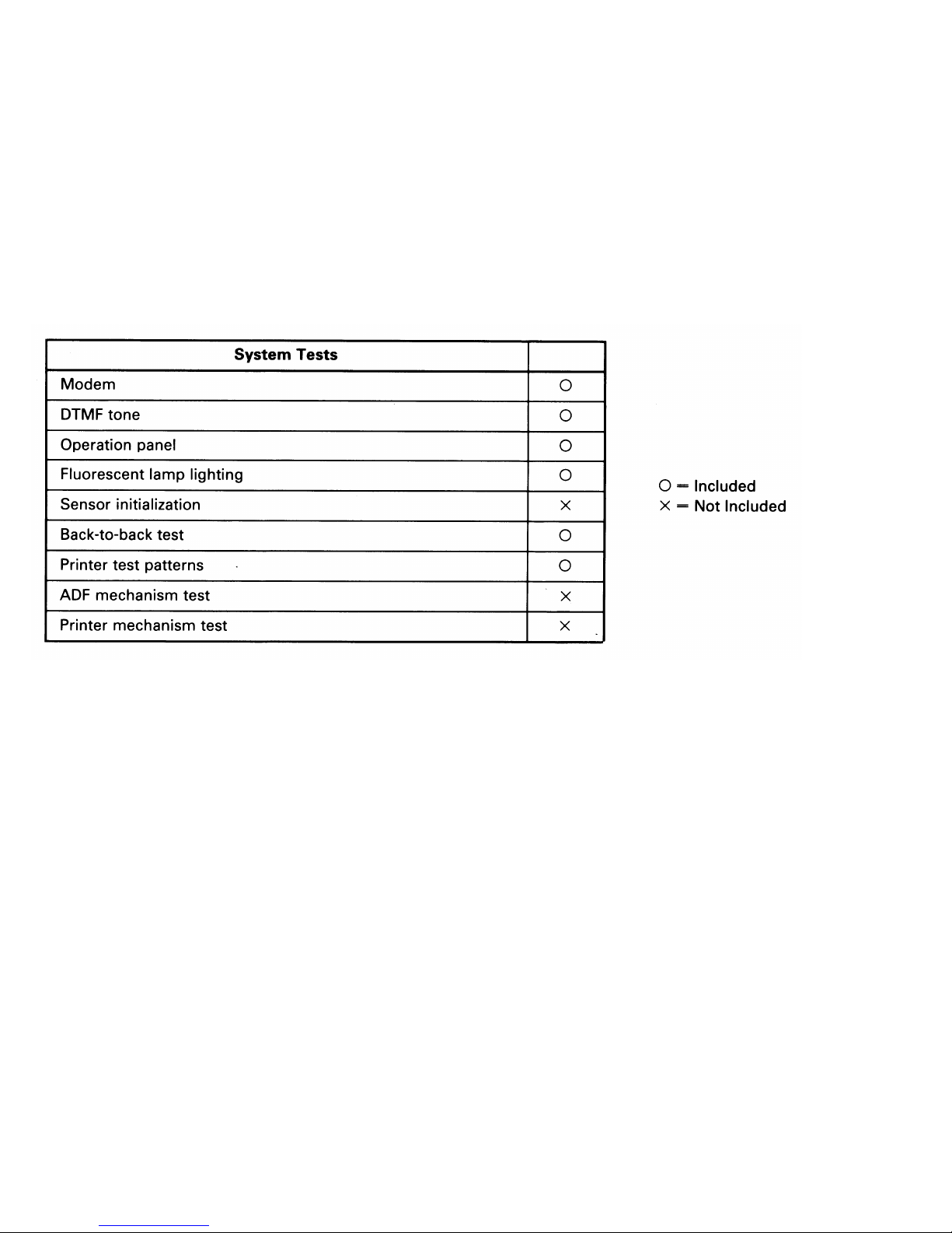
5-3-2 TEST MODE
This machine has the following function tests.
* Modem test (G2 and G3 signal transmission)
* Operation panel test
* Fluorescent lamp lighting
* Tone transmission (DTMF signals)
1. Entering and Exiting the Test Mode
1. Hold down the Stop key and switch the power on.
2. When “ENABLE SERVICE FUNC.” is displayed, press the Start key immediately. The following will appear.
DENSITY : MDM, LCD, LAMP
TEL : DTMF
The meaning of this display is as follows:
* Light the “Normal” LED to test the modem.
* Light the “Dark” LED to test the operation panel.
* Light the “Light” LED to light the fluorescent lamp.
* Light the “Speed Dial” LED to make a tone test.
3. Make the required tests according to the next few pages.
5 - 25
Page 77

4. After testing, press 6, 7, 8, 9 simultaneously.
Make sure that the Speed Dial LED is off.
2. Modem Test
1.
2.
3.
4.
5.
MODEM TEST
Select “Normal” contrast, then press Start.
The unit will go into off-hook mode.
Press the required keys to test the desired signal
(refer to the following table).
Example: 9600 bps; press Speed Dial then Start.
Note:
* The machine will return to standby after any one tone has been on for 8 minutes.
* If more than one LED is lit, the priority is:
Speed Dial > Voice Request > Detail > Contrast
Press Stop to return to step 3.
Press Stop once more to return to standby.
5 - 26
Page 78

— Signal Generation —
Signal
9600 bps
7200 bps
4800 bps
2400 bps
300 bps
2100 Hz
(CED)
1850 Hz
1650 Hz
1100 Hz
462 Hz
2100 Hz
(G2 video)
3. Operation Panel Test
1. Make sure that the Speed Dial LED is off.
Operation
Light the Speed Dial LED then press Start.
Select “Detail” resolution then press Start.
Select “Dark” contrast then press Start.
Select “Normal” contrast then press Start.
Select “Light” contrast then press Start.
Select “Light” contrast then press Copy.
Select “Normal” contrast then press Copy.
Select “Dark” contrast then press Copy.
Select “Detail” resolution then press Copy.
Light the Speed Dial LED then press Copy.
Light the Voice Request LED then press Copy.
LCD ALL DISPLAY
2. Select “Dark” contrast then press Start.
The indicators above keys should be lit and the green and
red indicators should be blinking.
3. Press the Stop key to return to standby.
5 - 27
Page 79

4.
5.
Fluorescent Lamp Lighting
1.
2.
3.
Make sure that the Speed Dial LED is off.
Select “Light” contrast then press Start.
The fluorescent lamp will light. It will remain lit for 8
minutes.
Press Stop to return to standby.
Tone Tests
1.
2.
3.
4.
Light the Speed Dial LED then press Start.
Press the key that corresponds to the required tone (see
the table on the next page).
Example: 697 Hz, press A.
Note:
The machine will return to standby if no key is
pressed for 8 minutes.
Press Stop after testing this tone.
Either:
Return to standby —
press Stop once more.
Or:
Test another tone —
go to step 2.
FLU LAMP ON
DTMF TONE
DTMF TONE
697HZ
DTMF TONE
5 - 28
Page 80

— Tone Generation —
Tone
DTMF 0
DTMF 1
DTMF 2
DTMF 3
DTMF 4
DTMF 5
DTMF 6
DTMF 7
DTMF 8
DTMF 9
Operation
Press 0
Press 1
Press 2
Press 3
Press 4
Press 5
Press 6
Press 7
Press 8
Press 9
Tone
DTMF *
DTMF #
697 Hz
770 Hz
852 Hz
941 Hz
1209 Hz
1336 Hz
1477 Hz
1633 Hz
Operation
Press *
Press #
Press A
Press B
Press C
Press D
Press E
Press F
Press G
Press H
Note: If any of keys A through H do not generate a tone, a keystroke program is stored in that key.
Print a Program list (function 73), erase the program (function 60), make the required tests, then re-input the
keystroke program.
5 - 29
Page 81

5-3-3 Printer Tests
It is not necessary to enter the Service Mode.
From standby:
* Press the Copy key, then immediately press a specified
key, depending on the desired printout.
Do not release the keys until the printer has started.
• Thin, closely spaced lines
Copy key + 1
• Thick, vertical stripes
Copy key + 2
• Pattern
Copy key + 3
• Dense diagonal stripes
Copy key + 4
5 - 30
Page 82

5-3-4 Dedicated Transmission Parameter Programming
Each telephone number programmed as a Quick Dial key or Speed Dial code has three bytes in RAM allocated for
transmission parameters.
Byte 1
Initial modem rate (bps)
(0, 0) = 9600 (0, 1) = 7200
(1,0) = 4800 (1, 1 )= 2400
Transmission level
Example: (1, 1, 0, 0) = –12 dB
Byte 2
Bit 0
Bit 1
Bit 7
Byte 3
compression
0: MH/MR 1: MH
Program Enable/Disable
0: Transmissions to this remote terminal will
DIS detection
0: First
use parameters as specified by the bit
1: Second (First DIS is ingored)
switch settings.
1:
The dedicated parameters in bytes 1 —> 3
ECM 0: Used 1: Not used
Short preamble
0: Not used 1: Used
will be used.
CCITT T1 time, in units of 2.56 seconds
Example: 60 seconds
60/2.56 = 24 approx
Byte 3 contains 18 (H) = 00011000
5 - 31
Page 83

The RAM addresses are as follows
ADDRESS
7850
NO NO ADDRESS NO ADDRESS NO ADDRESS NO ADDRESS NO ADDRESS
*1
I
786B
R
7886
12
78A1
21
78BC 30 78D7
7851
786C 7887
78A2 78BD 78D8
7852
786D 7888 78A3
78BE 78D9
A 7853
J
786E
S
7889 13 78A4 22 78BF
31
78DA
7854 786F 788A 78A5 78C0
78DB
7870 788B
78A6
78C1
78DC
K
7871
T 788C
14
78A7 23 78C2
32
78DD
7872 788D 78A8 78C3
78DE
7873
788E 78A9 78C4 78DF
L
7874
U
788F 15 78AA
24 78C5 33 78E0
785A 7875 7890 78AB 78C6
78E1
785B
7876 7891
78AC 78C7 78E2
D
785C M 7877 V 7892 16 78AD 25 78C8 34 78E3
785D 7878 7893 78AE 78C9
78E4
785E 7879
7894 78AF
78CA 78E5
E
785F
N
787A
W 7895 17 78B0 26 78CB 35
78E6
7860 787B 7896 78B1 78CC
78E7
7861
787C 7897
78B2 78CD 78E8
F
7862
O
787D
X 7898 18 78B3 27 78CE 36 78E9
7863 787E 7899 78B4 78CF
78EA
7864 787F
789A 78B5
78D0 78EB
G
7865
P
7880
10
789B
19 78B6 28 78D1
37
78EC
7866 7881 789C
78B7 78D2 78ED
7867 7882 789D 78B8 78D3
78EE
H
7868
Q
7883
11
789E 20 78B9
29 78D4
38
78EF
7869 7884 789F
78BA 78D5 78F0
786A
7885
78A0 78BB 78D6
78F1
*1: Service Station (Auto Service Call)
5 - 32
Page 84

NO ADDRESS
NO
ADDRESS
NO
ADDRESS NO ADDRESS NO ADDRESS NO ADDRESS
39
78F2
49 7910 59 792E 69 794C
79
796A 89 7988
78F3
7911
792F 794D 796B 7989
78F4 7912 7930 794E 796C 798A
40 78F5 50 7913 60 7931
70
794F 80 796D 90 798B
78F6 7914 7932 7950 796E 79BC
78F7 7915 7933 7951 796F
798D
41
78F8
51
7916
61
7934
71
7952
81
7970
91
798E
78F9 7617 7935 7953 7971 798F
78FA 7918 7936 7954 7972 7990
42 78FB
52
7919 62 7937 72 7955 82 7973 92 7991
78FC 791A 7938 7956
7974 7992
78FD 791B
7939 7957 7975 7993
43 78FE
53
791C
63
793A 73 7958 83 7976 93 7994
78FF
791 D
793B 7959
7977 7995
7900 791E 793C 795A 7978 7996
44
7901
54
791F
64
793D 74 795B 84 7979 94 7997
7902 7920 793E 795C
797A 7998
7903
7921
793F
795D 797B 7999
45
7904
55
7922
65
7940 75 795E 85 797C 95 799A
7905 7923 7941 795F 797D 799B
7906 7924 7942
7960 797E 799C
46 7907
56
7925
66
7943 76 7961 86 797F 96 799D
7908 7926 7944
7962 7980 799E
7909 7927 7945 7963 7981 799F
47 790A
57
7928
67
7946 77 7964 87 7982 97
79A0
790B
7929 7947 7965 7983 79A1
790C 792A 7948 7966 7984
79A2
48
790D
58
792B
68
7949 78 7967 88 7985 98 79A3
790E 792C 794A 7968
7986 79A4
790F
792D 794B 7969 7987 79A5
99 79A6
79A7
79A8
5 - 33
Page 85

5-3-5 Confidential File Printout
If the user has forgotten the password, you can find it on the system report (function 92).
However, if the user cannot find out the personal ID specified by the sender, which overrides the password, then use the
following procedure.
1.
2.
3.
4.
When the machine is in standby, simultaneously press 1, 2, 3, 4 and 5 to enter the service mode.
Press the Function key, enter 75, then press Yes.
Enter # 0.
Press Copy.
All memory files will be printed, including confidential files. However, they will not be erased from memory.
To erase the confidential files from memory:
1.
2.
3.
Change the data in RAM address 15E6 to 00, using function 91.
Switch the machine off, wait for
Re-store files for transmission.
ten seconds, then switch back on.
5 - 34
Page 86

5-4 QUALITY CHECKS
1. Copy Quality
1) Copy density
Method:
Visually check the density in the left, right and center.
Standard:
Density must be even in the left, right and center.
2) Skew
Method: Copy an R1 test chart using standard resolution.
Standard:
The difference in length between A and B must be as follows.
A4 or larger:
Less than 1% of the document length.
Smaller than A4: Less than 3% of the document length.
Correction: Clean the R1 and R2 rollers.
3) Intelligibility
Method: Copy an R1 test chart using standard resolution.
Check the characters in frame F
(see the chart on page 5-37).
Standard:
No characters must be missing in the subscan direction.
Correction: Check and adjust the following.
• Flatness
• Reduction rate
• MTF
Refer to section 7-2 for details.
5 - 35
Page 87

4)
Make another copy. If the copy is still defective, make a
printer test (see page 5-30) and check the SBU wave-
forms if necessary (refer to page 7-2).
5 - 36
Page 88

Page 89

2.
3.
4.
Test the operation panel display. Refer to page 5-27.
Check ADF and printer operation.
Communication Tests.
No.
1
2
3
Procedure
Call a remote unit and send 2 test charts,
one in standard and the other in detailed
resolution.
Receive 2 test charts.
Test the special communication functions
Check Items
1. Resolution selection.
2. RTI display.
3. Voice request function.
1 - RTI display.
2. Copy quality.
3. Automatic reception function
4. Voice request function.
1. Polling transmission.
2. Polling reception.
3. Turnaround polling.
4. Memory transmission.
5. Confidential reception.
6. Substitute reception.
7. Closed network.
5 - 38
Page 90

SECTION 6
REMOVAL AND REPLACEMENT
Page 91

Note:
If you will switch off the machine for more than 72
hours, do the following, if it is possible.
• Print out confidential rx files (see page 5-34)
• Print out files stored for transmission, and a SAF
File List. Note which documents were stored in
which files.
After switching the machine back on, re-store the files
for transmission.
Page 92

6-1 COVER REMOVAL
6-1-1 Front Cover
1. Remove the document tray (A) and copy tray (B).
2. Remove the cover plate (C) below the document exit (2
screws).
3 Open the copy exit cover.
4. Remove the small cover plate (D) to the front of the copy
exit cover (1 screw).
5. Open the right cover (E).
6. Remove the front cover (F) – remove 4 screws and dis-
connect the monitor speaker.
When replacing the cover plate (C), be sure that the hooks on
the bottom of the plate clip under the plate on the left end of
the upper unit.
6 - 1
Page 93

6-1-2 Rear Cover
See the diagram on page 6-1.
1. Remove the document and copy trays.
2. Remove the cover plate (C) below the document exit (2
screws).
3. Remove the small cover plate (G) to the rear of the copy
exit cover (1 screw). Open the copy exit cover to remove
the plate.
4. Disconnect the handset.
5. Open the right cover (E).
6. Remove the rear cover (H) – remove 4 screws.
6 - 2
Page 94

6-1-3 Top Cover
See the diagram on page 6-1.
1. Open the upper unit.
2. Remove the top cover securing brackets (I) – 2
screws.
3. Take off the top cover (J).
6-1-4 Operation Panel
See the diagram on page 6-1.
1. Remove the front cover (see section 6-1-1).
2. Remove the top cover (see section 6-1-3).
3. Remove the operation panel (K) – 2 screws, 1 ground
wire, 1 connector.
6 - 3
Page 95

6-1-5 Document Table
1.
2.
3.
4.
5.
6.
7.
Open the upper unit.
Take out the master unit (do not touch the master belt).
Remove the right inner cover strip (A) – 3 screws.
Remove the bracket (B) exposed after taking out the right
inner cover strip (2 screws).
Remove the two screws (C) holding the rear inner cover
(D). Do not take off the cover.
Open the ADF.
Remove the document table (E) – 2 screws.
Pull the top of the rear inner cover (D) towards the rear to
allow you to remove the document table.
While replacing, be sure to fit the three tabs (F) on the docu-
ment table into the three slots on the right edge of the document guide plate.
6 - 4
Page 96

6-2 ADF AND SCANNER
6-2-1 Feed and Pick-up Rollers
1.
2.
3.
4.
5.
6.
7.
Remove the document table (see section 6-1-5).
Remove the ADF clutch covers (4 screws).
See section 6-2-3.
Remove the rear inner cover (3 screws).
See section 6-1-5.
Remove the front inner cover (5 screws).
See section 6-9-1
Remove the lower document guide plate (5 screws).
CAUTIONS:
• Put the exposure glass and the two retaining plates in
a safe place.
• Do not lose the leaf spring from on top of the ADF
clutch.
• On reassembly, don’t forget to connect the ground
wire to the front exposure glass retaining plate.
Take out the pick up/feed roller and shaft assembly (A).
1) Push the roller shaft towards the DSB
2) Remove 2 E-rings
3) Slide the two bushings towards the rollers until they
are free of the pickup bracket (B)
4) Lift out the shaft
Take off the paper feed roller (C) and pick-up roller (D)
(1 clip each, 1 belt).
6 - 5
Page 97

6-2-2 Separation Roller
1. Remove the document tray and copy tray.
2. Remove cover (A) — 2 screws.
3. Open the ADF cover.
4. Remove ground wire (B) — 1 screw.
5. Open the upper unit.
6. Disconnect hinge (C) – 1 screw.
7. Remove the ADF cover (D) — 1 screw.
8. Remove the upper document guide plate (E) from the ADF
covver — 5 screws (F).
Caution:
Do not lose the ground wire.
9. Remove the two screws holding the separation roller
bracket (G).
10. Take out the separation roller (H).
Take care not to lose the spring (I) at the front end.
11. Remove the separation roller (2 screws).
When replacing:
• The spring (I) at the front end of the separation roller
must be fit into the circular depression (J) on the
separation roller shaft bracket.
• The two springs (K) on the upper document guide
plate must be fit into their respective circular depressions (L) on the ADF cover.
• Do not touch the rubber surface of the new roller, or
paper feed errors will develop sooner than normal.
6 - 6
Page 98

6-2-3 Fluorescent Lamp
1. Remove the document tray.
2. Open the ADF cover (A).
3. Open the upper unit.
(See section 6-1-5.)
4. Remove the ADF clutch covers (B)
— 4 screws.
5. Remove the screw holding the fluorescent lamp terminal
(c).
6. Slide out the lamp (D).
6 - 7
Page 99

6-2-4 SBU
1. Remove the top cover (see section 6-1-3).
2. Remove the adjustment knobs (A) — 1 screw each.
3. Remove the SBU (B) – 2 screws, 1 connector.
After replacement, carry out the scanner adjustment procedures in section 7-2, and copy a test chart.
6-2-5 VPU
1. Remove the top cover (see section 6-1-3).
2. Remove the VPU (A) — 2 screws, 2 connectors.
6 - 8
Page 100

6-3 CHARGE
6-3-1 Charge Corona Unit and Wire
1. Remove the operation panel (see section 6-1-4).
2. Remove the document table (see section 6-1-5).
3. Remove the front inner cover —
5 screws. See page 6-28.
4. Remove the front master unit guide rail (A) — 3 screws.
5. Remove the ozone duct (B) — 3 screws.
6. Remove the charge corona unit (C) – 2 screws.
7. Prise off the front endblock cover (D).
8. Carefully slide off the rear endblock cover (E).
9. Unhook the corona wire from the tension spring inside the
rear endblock cover.
10. Unhook the corona wire from the screw in the front endblock cover.
Do not remove the screw.
On reassembly:
• Do not touch the new corona wire with your bare
hands.
• Hook the new corona wire onto the rear endblock first.
• Set the corona wire in the front endblock groove (F).
• After installing both ends of the new wire, test the
action of the tension spring.
6 - 9
 Loading...