

Page 1
UMC600
Digital Weight Indicator
Installation Manual
30261
Page 2

Contents
About This Manual................................................................................................................................... 1
1.0 Introduction.................................................................................................................................. 1
1.1 Front Panel Keypad and Annunciators................................................................................................ 2
2.0 Installation and Wiring................................................................................................................ 4
2.1 Unpacking and Assembly ................................................................................................................... 4
2.2 Enclosure Disassembly ....................................................................................................................... 4
2.3 Cable Connections ............................................................................................................................. 4
2.4 Power Connections ............................................................................................................................ 4
2.4.1 AC Units and External DC Units ................................................................................................................. 4
2.4.2 AC/Battery Units ........................................................................................................................................ 4
2.5 VAC Conversion ................................................................................................................................ 5
2.6 Board Removal................................................................................................................................... 5
2.7 Instrumentation Setup ........................................................................................................................ 6
2.8 Load Cell Wiring ................................................................................................................................. 6
2.9 Standard Surge Protection Board....................................................................................................... 7
2.10 Hardware Configuration .................................................................................................................... 8
2.11 Serial Port Wiring............................................................................................................................... 9
2.11.1 Serial Port #1 Wiring: CPU KGR8924–1.................................................................................................. 10
2.11.2 Serial Port #2 Wiring: CPU KGR8924–1.................................................................................................. 11
2.12 Digitial I/O Wiring............................................................................................................................. 11
3.0 Configuration.............................................................................................................................. 13
3.1 Digital Configuration.......................................................................................................................... 13
3.1.1 Parameter Overview................................................................................................................................. 13
3.1.2 Configuration Procedure .......................................................................................................................... 13
3.1.3 Digital Configuration Parameters .............................................................................................................. 13
3.1.4 Normal Configuration Setup Parameters .................................................................................................. 19
3.2 Serial Configuration........................................................................................................................... 20
4.0 Options Configuration................................................................................................................ 22
4.1 Option 1 – Expanded Resolution ...................................................................................................... 23
4.2 Option 2 – Analog Output Option...................................................................................................... 24
4.2.1 Specifications........................................................................................................................................... 24
4.2.2 Test Modes.............................................................................................................................................. 24
4.2.3 Error Checking......................................................................................................................................... 24
4.2.4 Communication Verification...................................................................................................................... 24
4.2.5 Analog Wiring to Host Indicator................................................................................................................ 27
4.2.6 Analog Module Serial Pass-Through......................................................................................................... 27
4.3 Option 3 – Time and Date................................................................................................................. 28
4.4 Option 4 – Accumulator.................................................................................................................... 29
4.5 Option 5 – Expanded Serial Communications ................................................................................... 30
4.6 Option 6 – Linear Calibration............................................................................................................. 32
4.7 Option 7 – Serial I/O ......................................................................................................................... 33
4.7.1 Customizing Files..................................................................................................................................... 33
4.7.2 Macro File Setup...................................................................................................................................... 35
Technical training seminars are available through Rice Lake Weighing Systems.
Course descriptions and dates can be viewed at www.rlws.com or obtained by
Copyright © 2003 Condec. All rights reserved. Printed in the United States of America.
calling 715-234-9171 and asking for the training department.
Specifications subject to change without notice.
February 2003
Page 3

ii
4.7.3 Standard Serial Configuration................................................................................................................... 36
4.7.4 Option 7 Configuration ............................................................................................................................. 36
4.8 Option 8 – Analog Output/Relay Option............................................................................................ 38
4.8.1 Analog Output Option Wiring.................................................................................................................... 38
4.9 Option 9 – Front Panel Key Lockout Option...................................................................................... 39
4.10 Option 10 – Setpoints..................................................................................................................... 40
4.11 Option 11 – Remote Input Option.................................................................................................... 40
4.12 Additional Options........................................................................................................................... 41
4.12.1 Relay Output Board KHL8924................................................................................................................. 41
4.12.2 Relay Output/Input Board (KJN8924–) .................................................................................................... 43
4.12.3
Serial Command Option Parameters ................................................................... 46
5.0 Calibration.................................................................................................................................. 47
5.1 Zero Calibration ................................................................................................................................ 47
5.2 Single Slope Span Calibration........................................................................................................... 47
5.3 Five-Point Linear Calibration ............................................................................................................. 48
6.0 Normal Weighing Mode Operations.......................................................................................... 49
6.1 Display Test...................................................................................................................................... 49
6.1.1 Display Check.......................................................................................................................................... 49
6.1.2 EPROM Verification.................................................................................................................................. 49
6.2 LED Annunciators............................................................................................................................. 49
6.3 Function Keys................................................................................................................................... 49
6.4 Gross/Tare/Net Weighing Operations ............................................................................................... 49
6.4.1 Display Mode on Power Up...................................................................................................................... 49
6.4.2 ZERO Key Function.................................................................................................................................. 49
6.4.3 TARE Key Function .................................................................................................................................. 50
6.4.4 Overload and Underrange Conditions....................................................................................................... 50
6.5 Fixed Tare Entry................................................................................................................................ 50
6.5.1 Lb/Kg Conversion.................................................................................................................................... 50
6.6 Serial Output .................................................................................................................................... 51
6.6.1 Serial Data Formats.................................................................................................................................. 51
6.6.2 Demand Mode versus Continuous Data Output ....................................................................................... 52
6.6.3 Demand Print with Identification Number.................................................................................................. 52
6.7 Truck Weighing Mode....................................................................................................................... 53
7.0 Setpoints.................................................................................................................................... 55
8.0 Optional and Advanced Features............................................................................................... 62
8.1 Expanded Serial Communications .................................................................................................... 62
8.1.1 Demand Output Serial Data Format.......................................................................................................... 62
8.1.2 Continuous Condec Output Serial Data Format........................................................................................ 63
8.1.3 RS485 Data Formats................................................................................................................................ 63
8.1.4 Port 1 Remote Serial Commands............................................................................................................. 64
8.1.5 Full Duplex Parameter Entry/Recall........................................................................................................... 65
8.2 Delay Demand Print.......................................................................................................................... 65
8.3 Battery Option .................................................................................................................................. 65
9.0 Appendix.................................................................................................................................... 66
9.1 ASCII Character Chart ...................................................................................................................... 66
9.2 Parameter Control Code Chart ......................................................................................................... 67
9.3 Display and Error Messages ............................................................................................................. 67
9.4 Specifications ................................................................................................................................... 68
UMC600 Limited Warranty..................................................................................................................... 70
UMC600 Installation Manual
Page 4

About This Manual
This manual is intended for use by service technicians
responsible for installing and servicing the UMC600
digital weight indicator. This manual provides
information on installation, calibration, configuration,
Authorized distributors and their
employees can view or download this
manual from the Condec distributor
site at www.4condec.com .
and operation of the UMC600.
1.0 Introduction
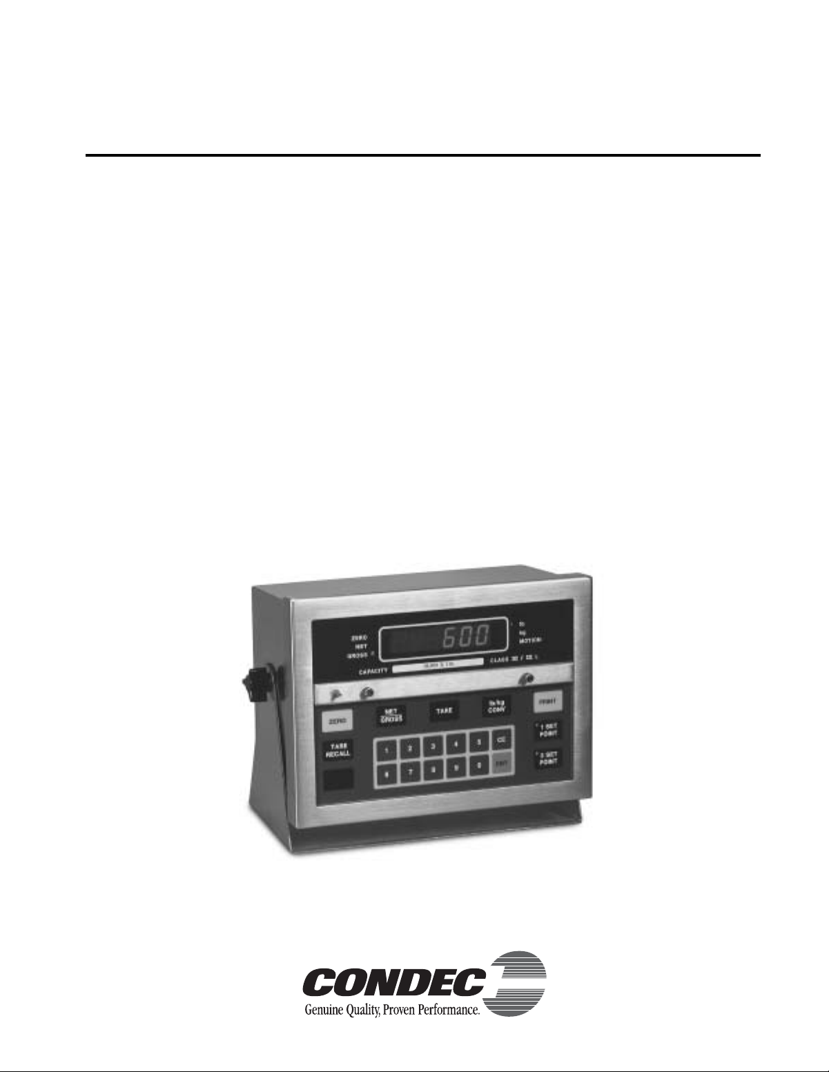
The UMC600 is a single-channel digital weight indicator designed to operate in a wide variety of scale and
weighing applications. The indicator is housed in a NEMA 4X stainless steel sealed case. The standard unit is
equipped with a tilt stand base for tabletop or wall mounting applications. The indicator front panel consists of a
21-button keypad, six se ven-segment display digits and six LED annunciators (see Figure 1-1 on page 2).
Standard features of the UMC600 include:
• Full front panel digital configuration and calibration.
• Zero and span temperature compensation to ensure compliance with NTEP and Canadian temperature range
requirements (–10 to 40°C).
• Nonvolatile memory stores data for calibration, temperature compensation, configuration parameters, auto or fixed
tare values, PAZ and AZM values, and setpoint values.
•Ten-thousand displayed graduations; 80,000 graduation expansion available.
Note: Use of more than 20,000 graduations may cause undesirable display instability in some applications.
µ
• Analog sensitivity to 0.3
•Ten updates per second, with selectable digital averaging and auto averaging; 5 Hz active analog filter for smooth
response.
• Excitation for eight 350
• Operable from AC, internal rechargeable battery with AC charger, or external DC input.
•Time and date print selection.
V/grad at 20,000 graduations.
Ω
load cells at 10 VDC.
Introduction
1
Page 5
2
1.1 Front Panel Keypad and Annunciators
Figure 1-1 shows the UMC600 front panel. The UMC600 display consist of six seven-segment display digits.
Table 1-1 lists the front panel keys and their functions.
Low Battery Annunicator
lb
kg
MOTION
PRINT
1 SET
POINT
2 SET
POINT
ZERO
TARE
RECALL
ZERO
NET
GROSS
CAPACITY
NET
GROSS
5000 lb. X 0.5
TARE
162738495
0
lb/kg
CONV
CE
ENT
Figure 1-1. UMC600 Front Panel
Panel Key
ZERO Provides push-button auto zero (PAZ) over ±1.9% or 100% full scale capacity. Operates only in gross
weighing mode.
GROSS/NET Switches the unit between gross and net weighing modes.
TARE Provides push-button tare entry over 100% of scale capacity. Pressing TARE key switches to net mode
and enters tare.
PRINT Provides a manual print function if unit is wired to serial printer or other data device. Also initiates truck
in/out weighing function if that feature is enabled. See Section 3.2 on page 20 for serial output
specifications.
lb/kg CONV Switches the displayed weight unit between pounds and kilograms.
TARE RECALL Press to recall tare value; LED annunciator lit when tare value is displayed. Also used as ID RECALL in
t
ruck weighing mode.
ON/OFF Provides power to the indicator.
Function
NOTE: On AC units, the ON/OFF switch is replaced by the blank key which becomes a start
key in setpoint batching modes.
SETPOINT 1 & 2 Push to enter or recall associated setpoint values.See Section 6.0 on page 49 for details.
0–9, CE, ENT
Numeric keyboard for entry of manual tare, setpoint values, and calibration data.
ENT
(Enter) keys.
(Clear Entry) and
CE
Table 1-1. Front Panel Key Functions
UMC600 Installation Manual
Page 6

Table 1-2 summarizes the front panel annunciator functions.
Annunciator
LOW BATTERY On when 12 VDC input voltage drops to approximately 11.4 VDC.
ZERO On when scale weight is within ±0.25 displayed graduations of zero. Used in gross or net weighing mode.
NET On when the indicator is in net weighing mode.
GROSS On when the indicator is in gross weighing mode.
lb/kg lb or kg LED is lit to show the current displayed weight units.
MOTION On when scale is in motion.
1 SETPOINT
2 SETPOINT
TARE RECALL Part of the TARE RECALL key, LED flashes when tare value is displayed.
ON/OFF On when the scale is operational.
On when the appropriate setpoint is energized or are flashing when the appropriate setpoint is recalled on
the display.
Function
Table 1-2. Front Panel Annunciators
Introduction
3
Page 7
4
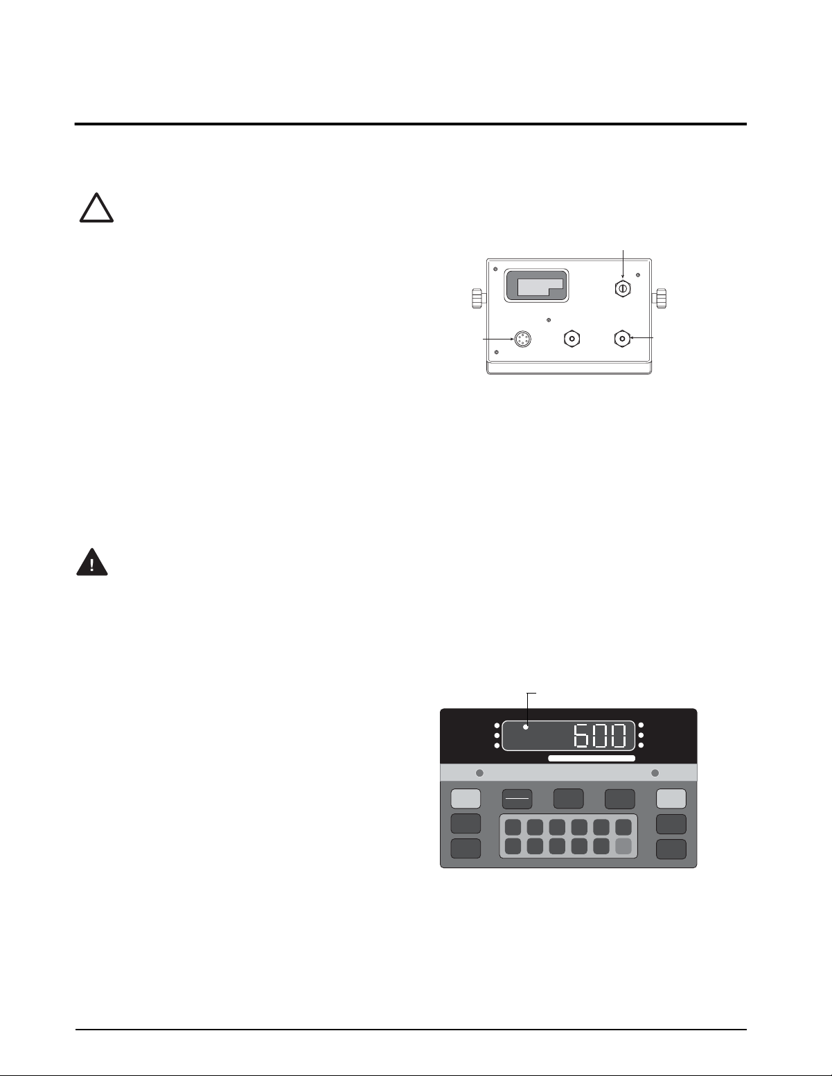
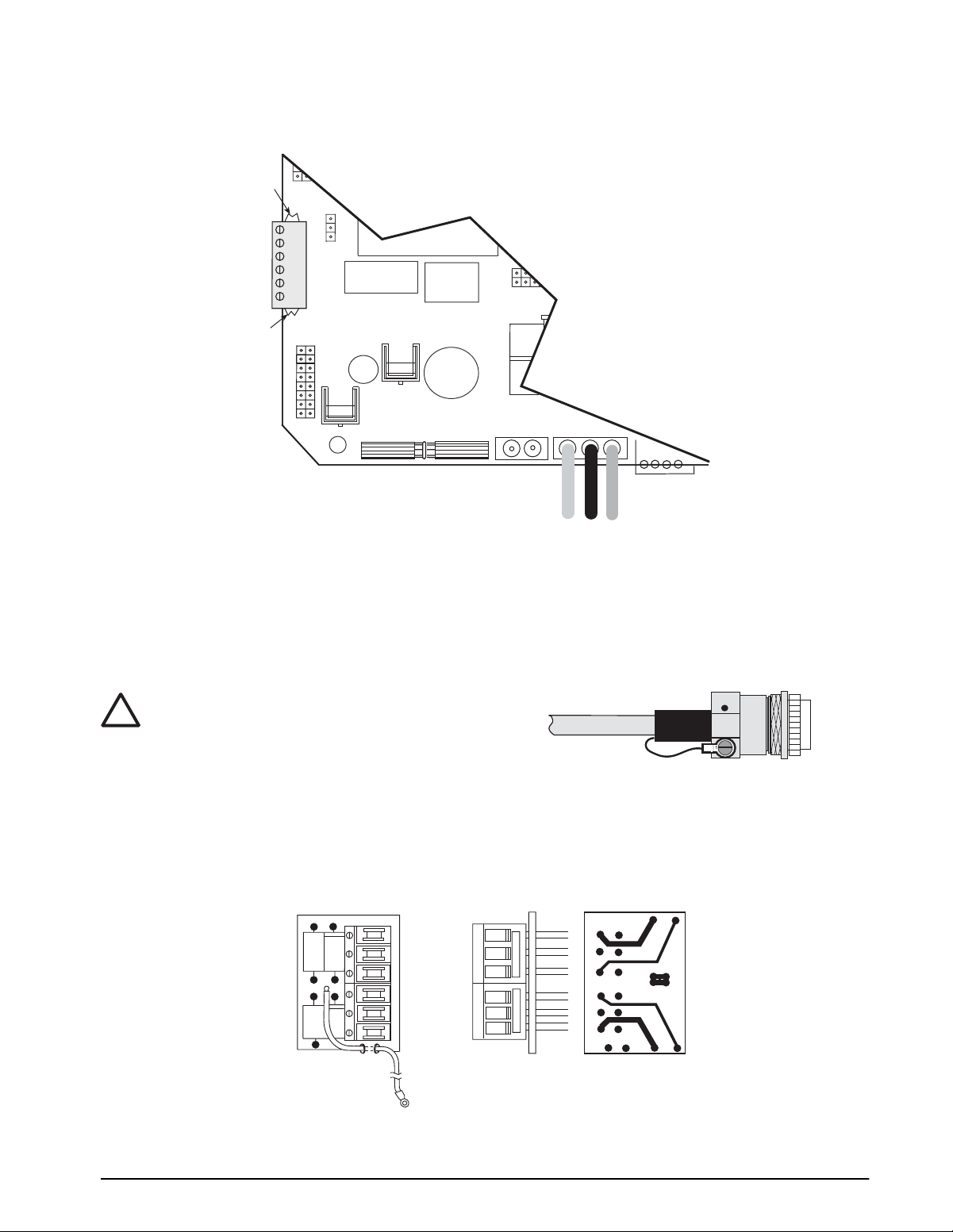
2.0 Installation and Wiring
This section describes the procedures for installing the UMC600 indicator, including connecting the load cell,
digital input and serial communications cables to the indicator. Instructions for CPU board replacement are
included, along with assembly drawings and parts list for the service technician.
Use a wrist strap to ground yourself
!
Caution
and protect components from
electrostatic discharge (ESD) when
working inside the indicator.
2.1 Unpacking and Assembly
All indicators are configured and tested prior to
shipment to ensure that they are fully functional.
Immediately after unpacking, visually inspect the
UMC600 to ensure all components are included and
undamaged. The shipping carton should contain the
indicator, tilt stand, the manual, and a parts kit. If any
parts were damaged in shipment, notify Condec and the
shipper immediately .
2.2 Enclosure Disassembly
The indicator enclosure consists of a load cell
connector and cord grips for communications cables.
the enclosure must be opened to connect the
communications cables.
The UMC600 has no on/off switch.
Warning
Before opening the unit, ensure the
power cord is disconnected from the
power outlet.
Ensure power to the indicator is disconnected then
remove the screws that hold the front bezel to the
enclosure body. Place the indicator face-down on an
antistatic work mat, then lift the enclosure away from
the front bezel. Set the enclosure aside.
2.3 Cable Connections
The UMC600 provides a load cell connector and three
cord grips for cabling into the indicator; one for the
power, and two to accommodate communications,
digital input, and analog output cables.
One of the two free cord grips comes with a plug
installed to prevent moisture from entering the
enclosure. Depending on your application, remove the
plug from the appropriate cord grip and install cables as
required.
Figure 2-1 shows the recommended assignments for the
UMC600 cord grips.
REAR VIEW
Analog Ouput, Digital Input
TB3 & 5
Load Cell
Connector
TB1
POWER
TB2 & 4
Serial
Communications
Figure 2-1. UMC600 Backplate
2.4 Power Connections
Standard units are powered by one of the following
options.
2.4.1 AC Units and External DC Units
Units are powered by standard 115 VAC power. The AC
power cord must be plugged into a 3-prong grounded
AC wall socket.
2.4.2 AC/Battery Units
The battery operated version of the UMC600 uses a 2.3
amp/hour rechargeable gel cell mounted inside the unit.
A low battery LED annunciator indicates when the
battery needs to be recharged (shown below) and
automatically shuts down when the battery output can
no longer maintain accurate weighing. Refer to Section
8.3 on page 65 for more information on the battery
option.
Low Battery Annunicator
lb/kg
CONV
ENT
lb
kg
MOTION
PRINT
1 SET
CE
POINT
2 SET
POINT
ZERO
NET
ZERO
TARE
RECALL
GROSS
NET
GROSS
CAPACITY
5000 lb. X 0.5
TARE
162738495
0
Figure 2-2. Low Battery LED Annunciator
UMC600 Installation Manual
Note: The unit can be operated while charging
however will take longer to recharge than the
recommended 12 to 16 hours of charging time.
,
Page 8

2.5 VAC Conversion
The UMC600 can be converted from 115VAC to
230VAC. The following steps are necessary to
complete this conversion.
Before beginning, be sure to
Warning
1. Disconnect power to the indicator. Loosen cord
grips and remove enclosure as described in
Section 2.2
2. See Section 2.6 for CPU board removal and
replacement instructions.
3. Remove the protective insulator panel from the
solder side of the CPU assembly .
4. Cut circuit traces between E7/E8 and E9/E10 as
indicated with a sharp instrument like a razor
blade or an x-acto knife. Refer to Figure 2-3.
Converting from 115V AC to 230V AC
Cut between
E7 and E8
disconnect the AC power source.
Failure to do so can result in injury
or death.
Jumper E8 to E9
Cut between
E9 and E10
2.6 Board Removal
If you must remove the UMC600 CPU board, use the
following procedure:
1. Disconnect power to the indicator. Loosen cord
grips and remove enclosure as described in
Section 2.2
2. Unplug all connections to the CPU board noting
where they are connected.
3. Remove the four screws from the corners of the
CPU board.
4. Remove the CPU board from the enclosure.
To replace the CPU board, reverse the above procedure.
Be sure to reinstall tie wraps to secure all cables inside
the indicator enclosure. Replace enclosure and torque
screws to 10 in - lb (1.13 N-m).
E8 E9 E10
E7
Circuit Side of CPU Board
Figure 2-3. Circuit Trace Setup
5. Add jumper, E8 to E9 using a properly insulated
wire with a minimum size of #22 AWG.
6. Replace the protective insulator panel.
7. Change the power cord.
8. Reassemble the unit, test, and label unit for
230VAC.
Installation and Wiring
5
Page 9
6
2.7 Instrumentation Setup
All indicators are configured and tested prior to
shipment to ensure that they are fully functional. The
unit can be turned on immediately after connecting the
input power and the load cells.
The UMC600 operates with the EPROM program
KDA1921-1(27C512). To verify the program installed
in the indicator, turn on the indicator and observe the
displayed value at the EP prompt (see Figure 2-4). The
EP prompt displays the family, set, and version level of
the installed EPROM.
EP–1.15
EPROM
Figure 2-4. EPROM Display
Set 1
To ensure that the UMC600 is in proper operating
condition, the indicator can be tested with a load cell
simulator. The input signal should be as close as
possible to the normal system millivolt value.
Figure 2-5 shows the simulator-to-indicator wiring
connection in a six-wire configuration. See Section 2.9
for more information.
Note: Six-wire configuration requires that the +SEN
lead be shorted to +EXC and the –SEN lead be shorted
to –EXC at the simulator only.
LOAD CELL
SIMULATOR
–EXC
+EXC
+SIG
–SIG
Figure 2-5. Wiring Connection to Simulator
Caution
!
–EXC
–SEN
+EXC
+SEN
+SIG
–SIG
Exceeding rated load cell load or
shorting excitation wires may
damage power supply.
Version 15
TO J1
CONNECTOR
UMC600
Notes:
•Test weights should be used to verify scale
performance.
• The tilt stand should be secured with 1/4-20 inch
screws. The location should be selected to of fer some
degree of protection for the indicator and its
associated hardware.
• Unprotected cable runs need to be installed in a
method to protect the cable from damage.
• All wiring must conform to the National Electrical
Code and RP 12.6.
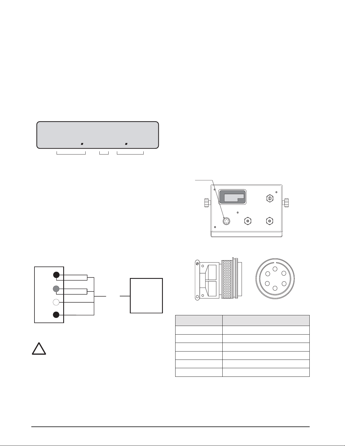
2.8 Load Cell Wiring
All units are equipped with a six-wire load cell
connector. The UMC600 is supplied with a six-pin
connector that needs to be attached to the existing load
cell cable by the installer.
Figure 2-6 shows the load cell output connector and the
location of J1 on the back of the indicator. Table 2-1
shows load cell connector pin assignments.
J1
Load Cell
Connector
TB3 & 5
TB1
Figure 2-6. J1 Load Cell Connector - facing
Pin
A +EXCITATION
B –EXCITATION
C +SIGNAL
D –SIGNAL
E +SENSE
F –SENSE
POWER
REAR VIEW
TB2 & 4
B
C
Function
A
F
E
D
UMC600 Installation Manual
Table 2-1. Load Cell Connector Pin Assignments
Page 10
The standard connection is designed for 4-wire (non remote sensing) use. To convert to 6-wire (remote sensing)
applications, cut the two PC traces on each end of TB1 as shown in Figure 2-7.
Traces
J5
TB1
+EXC
+SEN
+SIG
–SIG
–SEN
–EXC
Traces
Note: The load cell shield wire should be connected to
one of the load cell cable clamp screws located on the
load cell mating connector.
LOAD CELL CONNECTOR
654321
J3
S3
U18
Q5
U2
F1
K1
Figure 2-7. Load Cell Wiring From Indicator
J7
J6
+ Batt -
Check load cell
color code for
proper wiring.
GND LO HI
TO POWER SUPPLY
1
2
TB5
Six-Pin Female
Shielding is connected at only one end
!
Caution
(typically at the indicator end). If
connected at the strain gauge end,
disregard Figure 2-8.
Figure 2-8. Load Cell Shield Wire Connection
2.9 Standard Surge Protection Board
The UMC600 comes with a factory installed surge suppression board. The suppression board stops the flow of
excess voltage to the CPU board and attaches to TB1 on the CPU board just by pressing it into TB1 and tightening
the connector screws.
COMPONENT SIDE RIGHT SIDE CIRCUIT SIDE
CR3
CR2
CR4
CR1
+EXC
+SENSE
+SIG
–SIG
–SENSE
–EXC
Figure 2-9. Surge Protection Diagram
E1
E2
E3
E4
E5
E6
E7
CHGND
Installation and Wiring
7
Page 11
2.10 Hardware Configuration
Jumper pins are provided for:
• EPROM chip selection
• Front panel switch configuration (DC on/off or batch start)
•Power on/off relay configuration
• Dual channel (optional)
•Time and date option (SRAM selection)
These features are dependent on installed options and software. The location and jumper positions are noted in
Figure 2-10.
8
Dual Channel
(optional)
l 2 3
S7
S6
1 2 3
Enable Jumper 1-2
Disable Jumper 2-3
Front Panel On/Off
Switch Function
1 2 3
S4
S5
1 2 3
DC On/Off Jumper 1-2
Batch Start Jumper 2-3
Power On/Off
Relay
3
2
S3
1
Enable Jumper 1-2
Disable Jumper 2-3
For Toggle Switch Omit Jumper
TB1
+SIG
+SENSE
–SENSE
SHIELD
+EXC
Time and Date Option
3
2
S2
1
Enable Jumper 1-2 –
(1243 SRAM U4)
Disable Jumper 2-3 –
(1220 SRAM U4)
TB3
3
8
9
5
2
1
6
4
1
7
10
U20
S7
S6
S4
S5
R6
J4
J5
LOAD CELL CONNECTOR
–SIG
S3
654321
J3
U2
U18
F1
RF1
SHIELDED
A/D
Q5
U5
U7
J7
K1
DIGITAL OUTPUT
3
1
S2
U11
U4
EPROM Select
12 3
256k Jumper 1-2
512k Jumper 2-3
Figure 2-10. Jumper Pin Placement
Note: The lower left corner switch (S21) on the front panel, is used for the Start command in the standard setting of
S4 and S5, however, it becomes a power on/off switch when S4 and S5 are set to DC On/Off and S3 is set to the
Enable position.
UMC600 Installation Manual
Page 12
2.11 Serial Port Wiring
The UMC600 has two serial communications ports.
Port 1 supports full-duplex RS-232, or 20mA current loop (active or passive), or half-duplex RS-485. Switch S1
(shown in Figure 2-12), selects the interface protocol of Port 1.
Port 2 supports simplex (output only) RS-232, or 20mA current loop (active or passive).
Access to the serial communication ports is through the cord grips (TB2 and TB4) located on the back of the
enclosure (see Figure 2-11). See Figure 2-12 for serial I/O wiring termination assignments.
TB3 & 5
TB1
POWER
REAR VIEW
Figure 2-11. Serial Port TB2 Connector
U9
U13
J11
6
5
J10
4
3
2
1
1
SERIAL COMMUNICATIONS - 1
6
5
4
3
2
1
SERIAL COMMUNICATIONS - 2
S1
PASS
PORT 1 RECEIVE
1
2
3
4
RS232
20MA
RS485
ACTIVE
U8
TB2 & 4
Serial
Communications
TB4
RX+ (20 mA passive Port 1)
RX- (20 mA passive Port 1)
RX+ (20 mA active Port 1)
TX- (20 mA Port 2)
TX+ (20 mA Port 2)
TX- (20 mA active Port 1)
GND or RX 20 mA active Port 1
TX+ (20 mA active Port 1)
RX1 (RS-232 duplex Port 1) RD1
TX1 (RS-232 duplex Port 1) TD1
TX2 (RS-232 Port 2) TD2
TB2
Figure 2-12. Serial I/O Wiring Locations
Installation and Wiring
9
Page 13
2.11.1 Serial Port #1 Wiring: CPU KGR8924–1
Serial Port 1 supports full-duplex RS-232, or 20mA current loop (active or passive), or half-duplex RS-485. Switch
S1 (shown below), selects the interface protocol of Port 1..
TB3
3
8
9
5
2
1
6
4
10
7
DIGITAL OUTPUT
1
U9
U13
U7
U10
U1
GND LO HI
U4
C15
S1
3 41 2
PASS
PORT 1 RECEIVE
U15
U22 U21
J2
DIGITAL OUTPUT
1
2
1
3
TB5
U11
U19
RS232
20MA
RS485
ACTIVE
4
J11
J10
U8
1 – +TD1 20mA passive/RS-485A
2 – -TD1 20mA passive/RS-485B
3 – +TD2 20mA passive
4 – -TD2 20mA passive
TB4
6
5
4
RX+ (20mA passive Port 1)
RX- (20mA passive Port 1)
3
RX+ (20mA active Port 1)
2
TX- (20mA Port 2)
1
TX+ (20mA Port 2)
1
SERIAL COMMUNICATIONS - 1
6
TX- (20mA active Port 1)
5
GND or RX 20mA active Port 1
4
TX+ (20mA active Port 1)
3
RX1 (RS-232 duplex Port 1) RD1
TX1 (RS-232 duplex Port 1) TD1
2
1
TX2 (RS-232 Port 2) TD2
SERIAL COMMUNICATIONS - 2
TB2
optional
S1
PASS
RS232
20MA
3 41 2
RS485
ACTIVE
PORT 1 RECEIVE
TO POWER SUPPLY
Figure 2-13. Serial Port #1 Switch Location
Port Connector/Pin # RS-232 20mA Current Loop RS-485
1 TB2 - 2 TxD
1 TB2 - 3 RxD
1 TB2 - 4 +20mA TX+ OUT (active) *2
1 TB2 - 5 GND -20mA RX- IN (active) *1
1 TB2 - 6 -20mA TX- OUT (active)
1 TB4 - 3 +20mA RX+ IN (active)
-20mA RX- IN (passive)
1 TB4 - 4 +20mA RX+ IN (passive)
1 TB5 - 1 +20mA TX+ OUT (passive) RS-485-A *1 *3
1 TB5 - 2 -20mA TX- OUT (passive) RS-485-B *2 *3
Table 2-2. TB2, TB4, TB5 Pin Assignments (Serial Port #1 Communications)
*) Notes:
(
1. A pull-down biasing resistor (100K OHMS typical) should be installed between TB5-1 and TB2-5.
2. A pull-down biasing resistor (100K OHMS typical) should be installed between TB5-2 and TB2-4.
3. If the UMC600 is the last device (node) on the RS-485 network, a termination resistor (100 OHMS typical) should
be installed across TB5-1 and TB5-2.
10 UMC600 Installation Manual
Page 14
2.11.2 Serial Port #2 Wiring: CPU KGR8924–1
Serial port #2 supports simplex (output only) RS-232, or 20mA current loop (active or passi v e). The follo wing chart
illustrates Serial Port 2 pin assignments.
Port Connector/Pin # RS-232 20mA Current Loop
2 TB2 - 1 TxD
2 TB2 - 5 GND
TB2 - 6
2 TB4 - 1 +20mA TX+ OUT (passive)
2 TB4 - 2 -20mA TX- OUT (active)
TB5 - 3 +20mA TX+ OUT (passive)
TB5 - 4 -20mA TX- OUT (passive)
Table 2-3. TB2, TB4, TB5 Pin Assignments (Serial Port #2 Communications)
2.12 Digitial I/O Wiring
The standard unit has four outputs for setpoint and zero band control and four discrete inputs that allow the zero,
net/gross, and print function to be operated remotely by contact closure of these inputs to digital ground. Wire any
active digital input and outputs to connector TB3 on the CPU board. Table 2-4 shows the digital I/O assignments for
the TB3 connector and their description.
TB3 Pin Signal Description
Outputs
1 +5 VDC
2 DIG OUT 4 Dribble control assigned to setpoint 2 (defined in parameter 11), or a zero band output
when parameter 12 is selected for 1-50.
3 DIG OUT 3 Setpoint 2 output (defined in parameter 11).
4 DIG OUT 2 Dribble control assigned to setpoint 1 (defined in parameter 11).
5 DIG OUT 1 Setpoint 1 output (defined in parameter 11).
Inputs
Normal Mode Batch Mode
6 GND
7 DIG IN 4 Net/gross Abort
8 DIG IN 3 Zero Zero
9 DIG IN 2 Tare Start Batch
10 DIG IN 1 Print Print
Table 2-4. TB3 Pin Assignments (Digital I/O)
Inputs 7 through 10 allow the zero, net/gross, tare, and print functions to be operated remotely by contact closure of
these inputs to digital ground.
Installation and Wiring 11
Page 15

Typically, digital outputs control relays which operate other equipment. Outputs 1 through 4 allow for setpoint and
zero band control.
Operational Mode
Relay Board TB3
Tare Start Batch TB3-6 IN2
Zero Zero TB3-5 IN3
Net/Gross Abort TB3-4 IN4
Print Print TB3-3 IN5
TTL Inputs J11
KGR8924 CPU Normal Batch
Table 2-5. Relay Input Wiring
12 UMC600 Installation Manual
Page 16
3.0 Configuration
ZERO
NET
GROSS
TARE
lb/kg
CONV
Prior to calibration, the UMC600 must be digitally
configured, or assigned a set of operating parameters.
The three parameters listed in Section 3.1.1 are directly
related to calibration and must be set before proceeding
to calibration mode.
3.1 Digital Configuration
3.1.1 Parameter Overview
Table 3-1 on page 14 lists configuration parameters and
describes their values. The following paragraphs give
the procedure for configuring the UMC600.
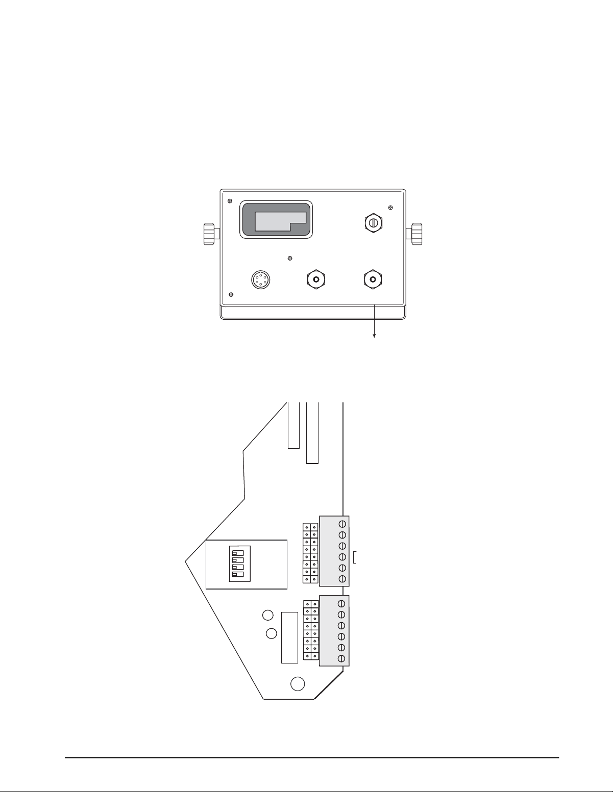
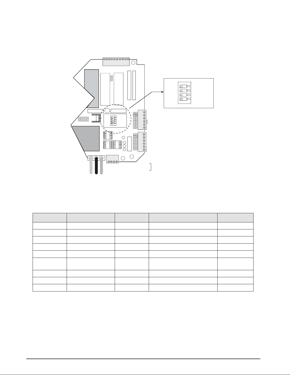
3.1.2 Configuration Procedure
1. Unscrew the two screws on the face plate
bracket (Figure 3-1). The bracket drops down,
exposing four program switches on the left side
of the indicator.
CE
ENT
lb
kg
MOTION
PRINT
1 SET
POINT
2 SET
POINT
342
1
OPEN
ZERO
TARE
RECALL
ZERO
NET
GROSS
CAPACITY
NET
GROSS
5000 lb. X 0.5
TARE
162738495
0
lb/kg
CONV
When configuration is complete, set SW1-2 down to
return the unit to normal operating mode.
DEAD LOAD (3)
CONF (2)
CAL (1)
NORM
Parameter
Identifier
ZERO
NET
GROSS
NET
ZERO
GROSS
TARE
RECALL
1
342
OPEN
162738495
Figure 3-2. Closing Switch 2
CAPACITY
5000 lb. X 0.5
TARE
0
Selected Data
lb/kg
CONV
CE
ENT
lb
kg
MOTION
PRINT
1 SET
POINT
2 SET
POINT
Figure 3-3 defines the functional operation of each key
on the front panel of the indicator when the unit is in the
the setup mode.
Zero Net/Gross Tare Units
Parameter
Select
NOTE: The TARE RECALL key functions as a previous
screen key in CONFIG mode.
Parameter Data
Select
Subparameter
Select
Subparameter
Data Select
Figure 3-3. Front Panel Key Functions
Figure 3-1. Accessing the Program Switches
2. Temporarily remove the unit’s flexible black
display overlay by gently pushing down and
lifting the panel up and out at its center to expose
the configuration and calibration instructions
printed on the surface below. The switch
function table defines the appropriate front panel
switch settings for the CONF and CAL modes.
3. Close switch SW1-2, marked
CONF (2), by
moving to the up position (see Figure 3-2). A
prompt appears with a parameter number and
data value.
The parameter identifier is a number, 1–14, that
correlates to the
CONFIG chart on the upper left of the
switch map panel. Selected data represents the value
being entered into the unit configuration data. For
example, 1 100 sets the indicator to 10,000 graduations
(see Table 3-2 on page 16).
Configuration 13
Page 17

3.1.3 Digital Configuration Parameters
Table 3-1 (shown below) shows an overview of the 14 configuration parameters and their description.
Table 3-2 on page 16 lists the configuration display prompts (Prompt 1), and their value selections for displayed
graduations. Prior to calibration, the UMC600 must be digitally configured, or given its set of operating parameters.
The first three parameter selections are directly related to calibration and must be set up before proceeding to the
calibration mode. These parameters include;
• number of graduation
• resolution
• decimal point location in the weight data, all of which define the scale capacity.
Parameter Description Values
1 Graduations NTEP to 10,000 (up to 80,000 available).
2 Display resolution 1, 2, 5, 10, 20, 50, 100
3 Decimal point 0.0, 0.00, 0.000, 0.0000, no decimal
5 Digital averaging 1, 2, 4, 8, 16, 32, A1 = 8-4-2; A2 = 16-8-4
6Tare mode ATNR, AUTO, FIXED, BOTH (inhibit with motion)
7 AZM band Off, 0.5, 1, 3, 5, and 10 divisions
Use 0.5 for H-44, bench, counter and livestock applications; use 3 for vehicle,
axle-load, and railroad scales
8 AZM/PAZ aperture ±1.9%, 100% of capacity includes push-to-zero, H-44: 1.9%
9 Motion Off, 1, 3, 5 divisions H-44: vehicle, axle, livestock, RR, 3.0; all other 1.0
10 Displayed units Lb, kg, con
11 Setpoint mode See Section 7.0 on page 55 for settings
12 Zero band Off, 1, 2, 3, 4, 5, 6, 7, 8, 9, 10, 20, 30, 40, 50
13 Weigh mode Normal, truck mode with transaction cancelled/stored, fixed/auto tare
14 Serial output Port 1, Port 2, demand, continuous, baud rate, G/T/N, or display
Table 3-1. Parameter Overview
14 UMC600 Installation Manual
Page 18
Figure 3-4 provides a graphic representation of the 14 configuration parameters associated with the UMC600.
Shown only if
SW1-2 is on
CONFIG
GRADS
100
selection
list,
see table 3-2
on page 16
Shown only if
SW1-1 is on
CALIBR
Options 1-11
shown only if
SW1-2 & 3 are on
OPTION 1 OPTION 2
RES
resolution
1
2
5
10
20
50
100
MOTION
band
Off
1
3
5
10
20
50
DECPT
decimal point
0.0
0.00
0.000
0.0000
OPTION 3
DISPLAY
kg
lb. conversion
digital average
A2=16-8-2
lb
OPTION 4
AVERAGE
1
2
4
8
16
32
A1=8-4-2
XXXXXXX XXXXXXXXXXXXXX
OPTION 5
ST PT
setpoint
off
SP
over/under
batch 1
batch 2
modes A - G
output
pos/neg
OPTION 6 OPTION 7 OPTION 8 OPTION 9 OPTION 10
TARE
enable tare
ATNR
AUTO
FIXED
BOTH
ZERO BAND
control output
AZM
band
OFF
0.5
1
3
5
10
Off
1
2
3
4
5
6
7
8
9
10
20
30
40
50
WEIGHT
mode
normal
truck
AZM/PAZ
band
1.9
FS
SERIAL
serial output
port 1 & 2
demand
continous
baud rate
G/T/N
display
OPTION 11
Figure 3-4. Configuration Menu
Refer to the following table numbers on the following pages for configuration display prompts.
Table Number Configuration Display Prompts Page
3-2 1 16
3-3 2-3 16
3-4 5-7 17
3-5 8-10 17
3-6 11-14 18
Configuration 15
Page 19
Prompt Display Interpretation Notes
Displayed Graduations Number of Displayed Graduations = Scale Capacity
15 500
110 1000
115 1500
120 2000
125 2500
130 3000
140 4000
150 5000
160 6000
180 8000
1 100 10000
1 120 12000 Not valid in NTEP legal-for-trade applications
1 140 14000
1 160 16000
1 180 18000
1 200 20000
1 300 30000 Not valid in legal-for-trade applications
1 400 40000
1 500 50000
1 600 60000
1 700 70000
1 800 80000
Resolution
Legal for trade values: 500–10000 graduations
These selections available only if option 1 (expanded resolution) is enabled (see
Section 4.1)
Table 3-2. Configuration Display Prompt 1
Prompt Display Interpretation Notes
Resolution / display divisions Resolution = Scale capacity
21 1
22 2
25 5
210 10
220 20
250 50
2 100 100
Decimal Point Location
30 No decimal point
3 0.0 xxxxx.x
3 0.00 xxxx.xx
3 0.000 xxx.xxx
3 0.0000 xx.xxxx
Displayed grads
Resolution is determined by the combination of parameters 2 and 3.
For example:
• If Parameter 2 = 1 and Parameter 3 = 0.00, display resolution is 0.01
• If Parameter 2 = 5 and Parameter 3 = 0.0, display resolution is 0.5
• If Parameter 2 = 10 and Parameter 3 = 0, display resolution is 10
Table 3-3. Configuration Display Prompts 2 – 3
16 UMC600 Installation Manual
Page 20
Prompt Display Interpretation Notes
No.
Digital Averaging
51 1 10/sec
52 2 5/sec
54 4 2.5/sec
58 8 1 sec
516 16 2 sec
532 32 4 sec
5A1 8-4-2 Variable
5A2 16-8-4 Variable
5A3 8-4-2 Variable Selection available when option 1 is enabled. see Section 4.1.
5A4 16-8-2 Variable
Tare Enable Selection of either fixed tare (Ft) or fixed tare and auto tare (both) in parameter 6
6 Atnr Auto (stored) tare only
6 Auto Auto (stored) tare only
6Ft Fixed (manual) tare
6 both Auto or fixed tare
AZM Capture Band (Displayed Grads)
7 oFF Off
7 0.5 ±0.5
71 ±1.0
73 ±3.0
75 ±5.0 Selection available when option 1 is enabled. See Section 4.1.
710 ±10.0
Averages
– no recall
only
Update
Rate
Display rate. Sets the update rate for displayed values.
allows up to a six digit fixed tare entry to be made using the numeric front panel
keys or, when configured for full duplex serial communication, a fixed tare entry
can be down loaded through the serial port.
Table 3-4. Configuration Display Prompts 5 – 7
Prompt Display Interpretation Notes
PAZ Aperture
8 1.9 ±1.9% of full scale
8FS 100% of full scale
Motion Band
Display Grads/sec
9 oFF Off
91 ±1.0
93 ±3.0
95 ±5.0
910 ±10.0
920 ±20.0 Selections available when option 1 is enabled
950 ±50.0
Table 3-5. Configuration Display Prompts 8 –10
Configuration 17
Page 21
Prompt Display Interpretation Notes
Display Base (lb/kg) lb/kg CONV key functions only if parameter 10 is set to 10 Con
10 lb lb display only
10 kg kg display only
10 Con lb (base) conversion
Table 3-5. Configuration Display Prompts 8 –10(Continued)
Prompt Display Interpretation Notes
Setpoint mode Four independent modes, three dependent modes. See Section 7.0 on page 55
11
Zero band control output Parameter 12 (zero band output) is not functional in certain setpoint
12 oFF off
12 1 ±1
12 2 ±2
12 3 ±3
12 4 ±4
12 5 ±5
12 6 ±6
12 7 ±7
12 8 ±8
12 9 ±9
12 10 ±10
12 20 ±20
12 30 ±30
12 40 ±40
12 50 ±50
Truck mode See “Truck Weighing Mode” in Section 6.7, page 53, for details
13
Serial configuration Section 3.2 for details
14
for settings.
configurations. See Section 7.0 on page 55 for details.
18 UMC600 Installation Manual
Table 3-6. Configuration Display Prompts 11 – 14
Page 22

3.1.4 Normal Configuration Setup Parameters
You must be in the configuration mode (SW1-2 closed to set the indicator from the PC) to be able to write
configuration parameters. To write commands the following Jxxyyzz<CR> sequence must be used. The following
parameters and their setup numbers are as follows:
Parameter 1 = Grads J0600 03 = Both J1100 02 = Ov.Un J1103 06 = 6 J1200 14 = 50
J0100 00 = 500 J1101 00 = HL J1103 07 = 7
J0100 01 = 1000 Parameter 7 = AZM Capture J1101 01 = TGT J1103 08 = 8 Parameter 13 = Truck in/out
J0100 02 = 1500 J0700 00 = Off J1103 09 = 9 J1300 00 = Nor
J0100 03 = 2000 J0700 01 = .5 J1102 00 = Pos J1103 10 = 10 J1300 01 = Tru
J0100 04 = 2500 J0700 02 = 1 J1102 01 = Zer J1301 00 = Can
J0100 05 = 3000 J0700 03 = 3 J1103 00 = Off J1301 01 = Str
J0100 06 = 4000 J1103 00 = Pos J1103 01 = 1
J0100 07 = 5000 Parameter 8 = Zero Range J1103 01 = Zer J1103 02 = 2 J1302 00 = Off
J0100 08 = 6000 J0800 00 = 1.9 J1103 03 = 3 J1302 01 = On
J0100 09 = 8000 J0800 01 = FS J1104 00 = Pos J1103 04 = 4.
J0100 10 = 10000 J1104 01 = Zer Parameter 14 = Serial
J0100 11 = 12000 Parameter 9 = Motion Band J1104 00 = Off J1400 00 = Off
J0100 12 = 14000 J0900 00 = Off J1100 03 = Bat 1 J1104 01 = S1 J1400 01 = SI
J0100 13 = 16000 J0900 01 = 1 J1101 00 = Off J1104 02 = S1.P J1400 02 = DU
J0100 14 = 18000 J0900 02 = 3 J1101 01 = S1 J1104 03 = S1.D (J1401 – 1405 for SI and DU)
J0100 15 = 20000 J0900 03 = 5 J1101 02 = S1.P J1104 04 = S.P.D. J1401 00 = Net
J0900 04 = 10 J1101 03 = S1.D J1401 01 = GTN
Parameter 2 = Resolution J1101 04 = S.P.D. J1105 00 = Pos
J0200 00 = 1 Parameter 10 = Units J1105 01 = Zer J1402 00 = Off
J0200 01 = 2 J1000 00 = Lb only J1102 00 = Pos J1402 01 = 1
J0200 02 = 5 J1000 01 = Kg only J1102 01 = Zer J1106 00 = Off J1402 02 = 2
J0200 03 = 10 J1000 02 = Lb/Kg Conversion J1106 01 = 1 J1402 03 = 3
J0200 04 = 20 J1103 00 = Off J1106 02 = 2 J1402 04 = 4
J0200 05 = 50 Parameter 11 - Setpoints J1103 01 = S2 J1106 03 = 3
J0200 06 = 100 J1100 00 = Off J1103 02 = S2.P J1106 04 = 4. J1403 00 = Off
J1100 01 = SP J1103 03 = S2.D J1106 05 = 5 J1403 01 = Co
Parameter 3 = Decimal Point J1101 00 = Off J1103 04 = S.P.D. J1106 06 = 6 J1403 02 = De
J0300 00 = 0 J1101 01 = S1 J1106 07 = 7
J0300 01 = 0.0 J1101 02 = S1.P J1104 00 = Pos J1106 08 = 8 J1404 00 = 3
J0300 02 = 0.00 J1101 03 = S1.D J1104 01 = Zer J1106 09 = 9 J1404 01 = 6
J0300 03 = 0.000 J1101 04 = S.P.D. J1106 10 = 10 J1404 02 = 12
J0300 04 = 0.0000 J1100 04 = Bat2 J1404 03 = 24
J1102 00 = Pos J1101 00 = Off Parameter 12 = Zero Band J1404 04 = 48
Parameter 5 = Digital Averaging
J0500 00 = 1 J1101 02 = S1.P J1200 01 = 1
J0500 01 = 2 J1103 00 = Off J1101 03 = S1.D J1200 02 = 2 J1405 00 = Off
J0500 02 = 4 J1103 01 = S2 J1101 04 = S.P.D. J1200 03 = 3 J1405 01 = Co
J0500 03 = 8 J1103 02 = S2.P J1200 04 = 4 J1405 02 = De
J0500 04 = 16 J1103 03 = S2.D J1102 00 = Pos J1200 05 = 5
J0500 05 = 32 J1103 04 = S.P.D. J1102 01 = Zer J1200 06 = 6 (J1406 for SI only)
J0500 06 = A1 J1103 05 = tol. J1200 07 = 7 J1406 00 = 3
J0500 07 = A2 J1103 00 = Off J1200 08 = 8 J1406 01 = 6
Parameter 6 = Tare J1104 01 = Zer J1103 02 = 2 J1200 10 = 10 J1406 03 = 24
J0600 00 = ATNR J1103 03 = 3 J1200 11 = 20 J1406 04 = 48
J0600 01 = Auto J1103 04 = 4. J1200 12 = 30 J1406 05 = 96
J0600 02 = FT J1103 05 = 5 J1200 13 = 40
J1102 01 = Zer J1101 01 = S1 J1200 00 = Off J1404 05 = 96
J1104 00 = Pos J1103 01 = 1 J1200 09 = 9 J1406 02 = 12
Table 3-7. Configuration Setup Parameters
Configuration 19
Page 23

3.2 Serial Configuration
The UMC600 has two serial ports. Both serial ports 1 and 2 are ASCII-compatible, 20 mA current loop, or RS-232
outputs. The serial format is compatible with most printers, scoreboards, and other remote devices. Each output can
be disabled, set for print on demand mode, or set to output data continuously .
Table 3-8 shows the configuration selections for parameter 14, which control the configuration of ports 1 and 2.
Note: Settings for simplex (14.S1) and duplex (14.dU) are the same except that ports 1 and 2 must have the same
baud rate when in duplex mode.
Subparameter
Parameter
Net/Gross Tare Lb/Kg Conversion Key which affects associated parameters
14. oFF Serial communications disabled
14. SI Port 1 and 2: simplex
Selection
14.1 Demand print configuration in net mode
14.2 Delay after carriage return (CR) enable
14.3 Port 1 configuration
14.4 Port 1 baud rate
14.5 Port 2 configuration
14.6 Port 2 baud rate
Subparmeter Data
Selection
14.1Gtn
14.1nEt
14.2oFF
14.2 1
14.2 2
14.2 3
14.2 4
14.3oFF
14.3 Co
14.3 dE
14.4 3
14.4 6
14.4 12
14.4 24
14.4 48
14.4 96
14.5oFF
14.5 Co
14.5 dE
14.6 3
14.6 6
14.6 12
14.6 24
14.6 48
14.6 96
Explanation
Three-line output G-N-T
Single line, net print
No delay after CR
1 second delay after CR
2 seconds delay after CR
3 second delay after CR
4 second delay after CR
Port 1 disabled
Continuous output
Demand print
300 bps
600 bps
1200 bps
2400 bps
4800 bps
9600 bps
Port 2 disabled
Continuous output
Demand print
300 bps
600 bps
1200 bps
2400 bps
4800 bps
9600 bps
20 UMC600 Installation Manual
Table 3-8. Parameter 14 Configuration Parameters
Page 24

Parameter
Net/Gross Tare Lb/Kg Conversion Key which affects associated parameters
14. dU Port 1 duplex
Subparameter
Selection
14.1 Demand print configuration in net mode
14.3 Port 1 configuration
14.4
In full duplex 14.4
is the baud
selection for ports
1 and 2
14.5 Port 2 configuration
Subparmeter Data
Selection Explanation
14.1Gtn
14.1nE
14.2oFF
14.2 1
14.2 2
14.2 3
14.2 4
14.3oFF
14.3 Co
14.3 dE
14.6 3
14.6 6
14.6 12
14.6 24
14.6 48
14.6 96
14.3oFF
14.3 Co
14.3 dE
Three line output G-N-T
Single line, NET print
No delay after CR
1 second delay after CR
2 seconds delay after CR
3 second delay after CR
4 second delay after CR
Port 1 disabled
Continuous output
Demand print
Ports 1 and 2 baud rate
300 bps
600 bps
1200 bps
2400 bps
4800 bps
9600 bps
Port 2 disabled
Continuous output
Demand print
Table 3-8. Parameter 14 Configuration Parameters
All serial characters in the data format are in ASCII and consist of the following default settings:
Data Formats
1 Start Bit
7 Data Bits
1 Parity Bit (Odd Parity)
1 Stop Bit
Table 3-9. Data Formats
The transmission of serial data can be initiated in either demand mode, continuous mode, or RS485. Refer to
Section 6.6 on page 51 for advanced detailed information on serial configuration options.
Configuration 21
Page 25

4.0 Options Configuration
The UMC600 offers a selection of optional features that
are available in the configuration of the indicator. The
options setup mode allows the operator to expand the
capabilities of the indicator. The available features are:
• Option 1 - Expanded resolution
• Option 2* - Analog output
• Option 3 - Time and date
• Option 4 - Accumulator
• Option 5* - Local area network\tag\id\counter
• Option 6 - Five-point linearization
• Option 7 - Smart serial I/O
• Option 8* - Analog output relay
• Option 9 - Keyboard lockout
• Option 10 - Setpoints
• Option 11 - Remote Input
NOTE: *Options 2, 5, and 8 require additional
hardware support. Options 1 through 11 are currently
available in the standard EPROM version 15.
To access digital option configuration, close switches
SW1-2 and 3 (Figure 4-1). Press and hold the ENT key
until OPtion appears on the display. If the option mode
is not enabled (all options turned off), dashes appear
across the display (- - - - -).
lb/kg
CONV
ENT
lb
kg
MOTION
PRINT
1 SET
POINT
CE
2 SET
POINT
ZERO
NET
GROSS
DEAD LOAD (3)
CONF (2)
CAL (1)
NORM
1
OPEN
CAPACITY
TARE
NET
GROSS
162738495
342
ZERO
RECALL
600 x 0.1
TARE
0
Figure 4-1. Close Switches SW1-2 and 1-3 for Option
Configuration
In the option mode, primary function keys (ZERO,
GROSS/NET, etc.) operate as secondary function keys
(Figure 4-2).
lb/kg
CONV
CE
ENT
lb
kg
MOTION
PRINT
1 SET
1 SET
POINT
POINT
PARAMETER
SELECT
2 SET
POINT
ZERO
NET
GROSS
ZERO
RECALL
SELECT
MODEL
OPTION
700
TARE
CAPACITY
NET
GROSS
162738495
ENABLE
1 2 4 5
DISABLE
TARE
600 lb. X 0.1
OPTION
MENU
0
Figure 4-2. Front Panel Keys with Alternate Functions in
Options Menu
Use the ZERO key to select options 1 through 11 or the
TARE RECALL key to scroll backward through the
options. To enable a selected option, use the
GROSS/NET key .
Some options, once enabled, may have an option
submenu available. Use the
TARE key to access the
option submenu. To make parameter selections in the
option submenu, use the
lb/kg CONV key. Display
prompting is provided in each case.
Key Functions Summary
Use the list below (Figure 4-3), as a quick reference
when selecting and configuring the options.
ZERO
ZERO
GROSS
TARE
lb/kg
CONV
PRINT
RECALL
ZERO – Increments option number
NET
NET/GROSS – Turns options ON/OFF
TARE – Steps through subparameters or functions as
ENTER for numeric changes
UNITS – Selects subparameters or digit position/decrements
digit for numeric changes
PRINT – Increments digit for numeric entries
TARE
TARE RECALL – Provides backstep in configuration mode
22 UMC600 Installation Manual
162738495
Figure 4-3. Quick Key Functions
0 – 9 – Used to enter numeric values directly ,
CE
including ZERO/SPAN values in Option 2
0
or TIME/DATE in Option 3 mode
ENT
Page 26

4.1 Option 1 – Expanded Resolution
XXXXXXX XXXXXXXXXXXXXXXXXXXXX OPTION 5
OPTION 4
OPTION 3
OPTION 2
CALIBR
CONFIG
OPTION 6 OPTION 7 OPTION 8 OPTION 9 OPTION 10
OFF
ON
EXPANDED
RESOLUTION
OPTION 1
OPTION 11
Enabling option 1 increases the indicator resolution by allowing display graduation selections beyond the normal
20,000 in parameter 1 of the configuration mode.
Up to 80,000 displayed graduations are available when this option is on; however, applying such high gains to the
data may cause undesirable display instability in some applications.
The expanded resolution (OP.1) is shown in T able 4-1
Prompt Display Interpretation
Expanded Resolution
OP.1 oF
OP.1 on
Option 1 Menu
Off
On (expanded up to 80,000 displayed graduations)
Table 4-1. Expanded Resolution Options
Figure 4-4. Option 1 Menu
and its menu structure in Figure 4-4.
Refer to Section 4.12.3 on page 46 for individual serial command option parameters for Option 1.
Options Configuration 23
Page 27

4.2 Option 2 – Analog Output Option
Indicator option 2 provides settings for zero, span, and trim adjustments for the analog output. The settings are all
digital therefore no potentiometers are required. During the trim adjustments for zero/span, the analog output is
forced to the zero/span previously selected in option mode parameters 2.5 and 2.6. While reading the analog output,
the trim is increased or decreased from 0 to ± 175 until the reading corresponds with the values entered in
parameters 2.5 and 2.6.
Option 2 enables the analog output option. The following features of analog output are:
• Converts serial data into analog: 0–10 VDC or 4–20 mA.
• Ordered as a kit, it must be operated remotely from the digital weight indicator.
• Self powered, 115/230 VAC provides isolated output.
• Automatic data checking/verification.
• Analog output tracks gross, net, or displayed weight.
• Full digital calibration (indicator front panel).
Serial data from the indicator is modified to include scaled information specifically for the analog output module.
The standard communications are also included to allow the module to pass-through printer or scoreboard
information.
NOTE: The serial pass-through does not have duplex capability.
The analog output is fully isolated with its own power supply and current loop communications. The analog module
can be located remotely up to 1000 feet from the indicator. After wiring and setting the module’s baud rate, the
remaining setup and calibration is done at the indicator.
4.2.1 Specifications
Current output is 4–20 mA with a maximum impedance less than or equal to 600Ω.
Voltage output is 0–10 VDC with a minimum load resistance of 1kΩ.
4.2.2 Test Modes
Switch settings are provided to force the analog output to zero, full scale, or to provide a continuous sawtooth
waveform for system checking.
4.2.3 Error Checking
Serial data is continually checked for parity, valid characters, and presence of communication. Loss of data is
indicated by forcing the analog output to a minimum value of -0.5 VDC or 3.2 mA (approximate). If the indicator is
in an overload condition, the analog output is forced to 5% over full scale. With the 4–20 mA output, an additional
alarm is provided to detect the lack of current (break) in the loop.
4.2.4 Communication Verification
An LED (DS1) is provided on the analog module:
• ON = Communications OK
• Pulse = Communications errors
• OFF = No power
24 UMC600 Installation Manual
Page 28

Table 4-2 shows the option 2 configuration parameters.
Prompt
Option
Display
Interpretation Notes
All off -------- Mode not enabled (options 1 through 10
turned off)
OP.2 OP.2 o F
OP.2 o n
2.1 dSP
2.2 P.1
2.3 OFF
2.4
2.5 Zr Enter weight value for analog zero using
2.6 FS Use the same procedure as 2.5 to enter
2.7 Zr.A ZERO TRIM: While measuring analog
Off Analog option disabled
On Analog option enabled
Analog tracks display
Gr
Analog tracks gross weight
net
Analog tracks net weight
Indicator data out on port 1 (to analog)
P.2
Indicator data out on port 2 (to analog)
Analog module does not pass serial data
dE
Analog module outputs serial on demand
Co
Analog module outputs serial continuously
Pass-through serial output baud rate
1200 baud
12
2400 baud
24
4800 baud
48
9600 baud
96
the numeric keys. The TARE key stores
new value; the display responds with
ENTER.
analog full scale value.
output, use lb/kg CONV and PRINT keys
to increment/decrement the zero value.
Increment/decrement function forces an
analog cal mode zero output. The TARE
key stores the new value.
—
—
—
Use standard indicator setup for serial configuration
under menu 14 (configuration Switch S-2 closed) to
establish communications before using the option 2
menu. Port 1 from the indicator to the analog module
must be set for the desired baud rate and be in
continuous output mode. In the option 2 menu, set the
indicator port to 1. On analog board S1, set baud rate
switches (1 and 2) to match menu 14.
—
The display for parameters 2.5 through 2.8 alternate
between the parameter selection and the actual data
value currently entered. This alternation will continue
until the data for the parameter has been increased or
decreased.
TARE key to store. The display will again resume
switching between parameter and data.
NOTE: After entering new data, use
2.8 SP.A SPAN TRIM: Same as 2.7 except a span
analog cal mode output is provided.
Table 4-2. Option 2 Configuration
Options Configuration 25
Page 29

S2
S
Figure 4-5. Analog Module Setup and Wiring
1 23456789
456
2
1
3
SW1 Setting
7
89
Baud rate
1 2
1200 Off Off
2400 On Off
4800 Off On
9600 On On
Mode 3 4
Normal operation Off Off
0 VDC/4 mA (test only) On Off
10 VDC/20 mA (test only) Off On
0–10 VDC/4–20 mA ramp (test only) On On
Table 4-3. Baud Rate and Switch SW1 Settings
TB1 Description TB2 Description
1 4–20 mA 1 Zero
2Ground 2 Gross/Net
3 0–10 Vdc output 3 Tare
4 Alarm 4 Start
5Ground A 5 Ground (–20 mA input) common
6 +20 mA TXD 6 RS-232 TXD
7 –20 mA TXD 7 +5 VDC
8 +20 mA RXD 8 –20 mA
9 -20 mA RXD (input) 9 Demand print
NOTE: Jumper TB1-8 to TB2-7 (5 VDC) to make the analog output module an active device.
Table 4-4. Description of Terminal Boards TB1 and TB2
26 UMC600 Installation Manual
Page 30

4.2.5 Analog Wiring to Host Indicator
The following diagram illustrates the wiring layout to the host indicator.
RX+
TX+
RXTX-
Active 20 mA
TB4
3
4
5
6
TX+
6
RX+ (passive)
8
TX- (analog)
7
9
RX-
TX+
active
TX-
PORT 2
20 mA
TB4
▲
1
2 Rx - (analog)
▲
Rx+ (passive)
8
9
TB2
PORT 1
Figure 4-6. Analog Wiring to Indicator
4.2.6 Analog Module Serial Pass-Through
The serial data from the host digital weight indicator is provided as a simplex output with the same format as the
host.
ANALOG TB2
DEMAND
COMMON
+5 (-TD)
TX(-TD)
9
5
7
8
➤
➤
PRINT
20 mA
6
TX
RET
5
RS-232
KBY7116/4
Figure 4-7. Pass Through Wiring
The Option 2 configuration parameters are graphically illustrated in Figure 4-8, shown below.
CONFIG
OFF
CALIBR
OPTION 1
ON
2.1
dSP
Gr
net
OPTION 2
2.2
P.1
P.2
OPTION 3
OPTION 4
2.3
OFF
dE
Co
Figure 4-8. Option 2 Menu
XXXXXXX XXXXXXXXXXXXXXXXXXXXX OPTION 5
OPTION 6 OPTION 7 OPTION 8 OPTION 10
2.4
12
24
48
96
2.5
Zr
2.6
FS
OPTION 9
2.7 2.8
Zr.A
Refer to Section 4.12.3 on page 46 for individual serial command option parameters for Option 2.
OPTION 11
SP.A
Options Configuration 27
Page 31

4.3 Option 3 – Time and Date
The main purpose for time and date is to allow the operator to quickly change the time when the time changes
between standard and daylight savings time.
The time and date clock is attached to the battery-backed memory (U4) and will continue running when the
indicator is off.)
Prompt Display Interpretation Notes
Time and date option Time and date settings can be directly
OP.3 oFF Off (time and date disabled)
OP.3 On On (time and date enabled)
3.1 Std
dLs
3.2 12
Standard Time
Daylight Savings Time
Selects 12- or 24-hour time display
24
3.3 A
AM (A) or PM (P) setting when 12-hour clock is selected
P
3.4 Un
Ab
Selects the location of printed time and date data: under (Un),
above (Ab), or on the same line (On) as weight data.
on
3.5 LEtnOPrints date in letters (LEt) or numbers (nO).
For example: Sept 1, 1999 vs. 09/01/99
3.6 tI Time. Use numeric keys to enter the time in hours, minutes and
seconds (HHMMSS), then press the
ENTER key (see Note
below)
3.7 dA Date. Use numeric keys to enter the date in month, day and
year format (MMDDYY), then press the
ENTER key (see Note
below)
accessed in normal running mode by
holding down both the
0 and 3 keys for
a few seconds. The operator can then
make changes without using option
switches. To exit, press the
0 key.
The display for parameters 3.5 and 3.6
alternates between the parameter and
the current data value. This continues
until new data is entered using the
numeric keys. After entering new data,
press
ENTER again to alternate the
display.
Table 4-5. Option 3 Configuration Selections
NOTES:
• Prior to setting the time and date, select the current time (dLs–daylight savings or Std–standard). This
feature selection allows the operator to increment or decrement the time by one hour when clocks are
changed from dLs or Std without having to re-program the entire time.
•Time and date can be directly accessed in normal running mode by pressing both the
0 and 3 keys for a fe w
seconds. This allows the time or date to be changed without using the option switches. To exit you must be
at 3.1 to 3.5 and then press the 0 key. This sequence does not work with 3.6 or 3.7.
Option 3 configuration parameters are graphically illustrated in Figure 4-9.
CONFIG
OFF
CALIBR
OPTION 1
ON
TIME/DATE
Off
On
OPTION 2
DLS
Std.
dLs
OPTION 3
OPTION 4
HR
12
24
XXXXXXX XXXXXXXXXXXXXXXXXXXXX OPTION 5
Figure 4-9. Option 3 Menu
OPTION 6 OPTION 7 OPTION 8 OPTION 10
A–PT
Am
Pm
POS
Under
Above
On
TYPE
LEt
letter
nO
number
OPTION 9
hh.mm.ss
OPTION 11
TI DATE
mm/dd/yy
Refer to Section 4.12.3 on page 46 for individual serial command option parameters for Option 3.
28 UMC600 Installation Manual
Page 32

4.4 Option 4 – Accumulator
The accumulate function is used to add weight data to a register for later access by the user. The accumulator can
keep a running total of weights entered, either automatically using setpoints, or manually pressing the
when the accumulate function is active.
The UMC600 has a ten digit accumulator available when Option 4 is enabled. To protect against multiple
accumulations of data, the accumulator option has a selectable return to
ZERO ACCUMULATION BAND feature.
This feature ensures that the weight display must return to a value inside the zero band before the accumulator can
be performed.
Caution
!
Option Prompt Display Description
OP.4 OP.4 oF
Parameter 10 in the configuration mode should be set for lb or kg base only. This avoids adding
incorrect data to the accumulator when switching between lb base and kg conversion. Clear the
total whenever the capacity is changed.
off
OP.4 on
4.1 oFF
on – accumulator enabled
Zero band “off” data accumulator, anytime the
1
± 1 Display graduations
2
± 2 Display graduations
3
± 3 Display graduations
4
± 4 Display graduations
5
± 5 Display graduations
6
± 6 Display graduations
7
± 7 Display graduations
8
± 8 Display graduations
9
± 9 Display graduations
10
± 10 Display graduations
20
± 20 Display graduations
30
± 30 Display graduations
40
± 40 Display graduations
50
± 50 Display graduations
PRINT key is pressed.
Table 4-6. Option 4 Configuration Parameters
PRINT key
Accumulation
Accumulators are activated in the following ways.
• Activated by pressing the
• Activated by the
PRINT COMMAND in the auto batch mode (parameter 11 bAt2).
PRINT key.
• If the data is valid (not in motion, overload, etc.) the display data is added to the content of the accumulator
and the display prompts with
To prevent multiple accumulations of weight data, a
PRINT when configured for demand print or Acc if not in demand.
ZERO threshold detection band (in display graduations),
requires the display data to return to zero before another accumulation/print can be performed.
Total Recall
To view the contents of the accumulation register on the display, use the following steps: press TARE RECALL
which is redefined as TOTAL RECALL key when option 4 is enabled. The tare recall LED flashes indicating the
instrument is in the total recall mode. While in total recall, the contents of the accumulator can be printed out when
the
PRINT key is pressed. If the serial output is configured for continuous output, the total is continuously printed
out anytime the indicator is placed in total recall mode.
Total Reset
The total can be cleared to zero when in the TOT AL RECALL display mode by:
1. Press the
2. Press
Clear.
CE key. The unit prompts with the display message Sure.
CE a second time to clear the contents of the accumulator resetting it back to zero. The display prompts
Refer to Section 4.12.3 on page 46 for individual serial command option parameters for Option 4.
Options Configuration 29
Page 33

4.5 Option 5 – Expanded Serial Communications
The expanded serial communications options provide RS-485 communications for the UMC600. Option 5 features
include:
• Duplex communication for up to two weight indicators on a single serial port.
• RS-485 half-duplex with U21 installed.
• RS-485 full-duplex available with U21 and the
• Direct keyboard access to the indicator address in normal operating mode.
• Poll/answer protocol.
• Unit address 1 - 98.
•Tag mode that adds the programmed address to standard serial output format.
• Stored ID mode allows an identification number to be held until written over by a new one.
• Counter sequentially counts on each valid print. Counts from 1 – 999,999.
TAG/LAN
Under option 5 there are two modes of serial operation that can be selected:
•TAG mode – Adds a two digit address to the standard serial format which “tags” printed data with the
UMC600’s address. This feature is useful when more than one indicator is set up on a site and serial data
needs to be identified with the indicator from which it was generated.
• LAN mode – Local Area Network can be configured as a two wire (half duplex) RS-485 serial
communication by installing the driver chip into socket U21 or 5.2 LAN (full duplex) RS-485/RS422 with
the additional installation of the KBT7116-13 kit.
Option Prompt Display Explanation Additional Notes
OP.5 OP.5 oF
OP.5 on
5.1. tAg
LAn
5.2. Addr Allows selection of indicator address from
5.3. oF
on
5.4. oF
on
5.5. cnt Preset initial counter value from 0 – 999,999 See notes from 5.2
off
on Option 5 enabled
Tag mode (data labeled with an address
Local Area Networking (RS-485)
1 – 98).
ID held option off
ID option enabled
Counter off
Counter option enabled
KBT7116-13 kit installed.
When either 5.2 or 5.5 is selected, the display
alternates between 5.2 Addr or 5.5 cnt, respectively
and its current numeric value. The alternation of the
display occurs until a new value is selected.
Addresses can be accessed in the normal
operating mode by pressing
simultaneously. Pressing
seconds allows changes to be made without having
to access the dip switches. To exit, press
RECALL for several seconds.
0 and 5
0 and 2 for several
TARE
Table 4-7. Option 5 Configuration
NOTE: Port 1 configuration (parameter 14) must be set for duplex, (du), demand mode (de), and the appropriate
baud rate. See Section 3.2 for wiring and serial protocol.
The option 5 configuration parameters are graphically illustrated in Figure 4-10.
30 UMC600 Installation Manual
Page 34

CONFIG
CALIBR
OPTION 1
OPTION 2
OPTION 3
OPTION 4
XXXXXXX XXXXXXXXXXXXXXXXXXXXX OPTION 5
OPTION 6 OPTION 7 OPTION 8 OPTION 10
OPTION 9
OPTION 11
OFF
ON
5.1
tAg
LAn
5.2
Addr
5.3
oFF
5.4
oFF
On
On
Figure 4-10. Option 5 Menu
Receive From Indicator Transmit From Indicator
Data Entry Command Type Echo Data Resp.
Poll P Wt. Poll P Weight data
Remote Z Zero Z Status
GGross G Status
N Net N Status
TTare T Status
B Start Bat B Status
Setpoint
xxxxx)
(
Fixed Tare
xxxxx)
(
Calibration
xxxxx)
(
Calibration Data
Zero Cal CZE Zero Entry CZR Zero Cal Data
Span Cal CSE Span Entry CSR Span Cal Data
SEn Enter SRn Setpoint value
SRn Recall SRn Setpoint value
FE Enter FR Fixed tare value
FR Recall FR Fixed tare value
Z Zero Cal No response
SE Span Cal
CZR Zero Recall CZR Zero Cal Data
CSR Span Recall CSR Span Cal Data
5.5
Cnt
Table 4-8. Table of Commands and Data
Refer to Section 4.12.3 on page 46 for individual serial command option parameters for Option 5.
Options Configuration 31
Page 35

ID HELD
This function is enabled when 5.3 is selected On. When ID held is enabled, the current keyed in ID number is stored
in memory and is sent out with each valid demand serial print. There are two methods of ID entry.
• Gross/Net mode – use numeric keys to enter the desired ID number, then press
• Gross mode only – key in numeric value and press
ENTER. This stores the new ID number for the next
PRINT.
print command.
NOTE: Leading zero entry not allowed.
NOTE: If a zero value is entered as an ID number, there is no printout of an ID number.
Counter
The counter feature is a six digit counter that sequentially increments by one on each valid print command in the net
mode only . It is enabled when 5.4 is on and has a range from 0 - 999,999.
4.6 Option 6 – Linear Calibration
There are five calibration points that can be entered sequentially. Calibrations using fewer than five points will
linearize the curve up to the last data point.
Enabling option 6 places the indicator in a linearization calibration when the unit is in the calibration mode (SW1-1
closed on front panel DIP switch). Use the five-point linearization procedure outlined in Section 5.3 on page 48 to
perform a scale calibration when option 6 is enabled.
The five-point linearization calibration (OP.6) is shown in T able 4-9
.
Prompt
Display
Five-point linearization
OP.6 oFF Off —
OP.6 on On Enter up to five linearization points
Interpretation Notes
Table 4-9. Option 6 Configuration Selections
Refer to Section 4.12.3 on page 46 for individual serial command option parameters for Option 6.
32 UMC600 Installation Manual
Page 36

4.7 Option 7 – Serial I/O
The serial I/O option offers flexibility for an operator to customize the serial output format for individual system
requirements. The selections under option 7 can be divided into three groups.
• Customizing of serial output data.
• Setup of MACRO files.
• Those files that affect serial operation.
These sections are addressed in detail below.
4.7.1 Customizing Files
The serial I/O option offers flexibility for an operator to customize the serial output format for individual system
requirements but must be limited to 30 character codes. The selection of the associated custom print file is
performed automatically by serial port and the data mode (gross, net, total recall, or special) that the UMC600 is
currently in at the time of a print.
The custom print supports:
• Specifying starting and terminating characters (STX, CR, LF)
• Adding printer control characters
• Custom headers and titles
• Customizing units to ounce, tons, or pounds
• Customized parameters such as gross weight instead of GR
• Custom insertion of special parameters such as time/date and identification number
• Delays where and when required
•Truck mode custom printing
• Custom continuous serial protocol
• Custom “P” print out in duplex mode
NOTE: Custom print does not support RS485 protocol.
Customizing
File Normal Mode Truck Mode Macros (8) Macro Parameter
Codes
Port 1 7.1 Gross data Truck mode data is printed only
7.2 Net data - must have a tare
weight (press T ARE button) for
file 7.2 to be printed.
7.3 Prints total data when totalizer
(option 4) is enabled.
7.4 Special (future use) 7.12 603
Port 2 7.5 Gross data Truck entry 7.13 604
7.6 Net data - must have a tare
weight (press T ARE button) for
file 7.2 to be printed.
7.7 Prints total data when totalizer
(option 4) is enabled.
7.8 Special (future use) Truck fixed tare 7.16 607
on Port 2. Port 1 files remain in
normal mode.
Option 7 disabled - unit prints
in default format.
Option 7 enabled - print mode
will print to its default format
unless a designated file is set to
off.
Truck out empty 7.14 605
Truck out full 7.15 606
7.9 600
7.10 601
7.11 602
Table 4-10. Customized Serial I/O Forma
Options Configuration 33
Page 37

Option 7 Menu
CONFIG
CALIBR
OPTION 1 OPTION 9
OPTION 2
OPTION 3
OPTION 4
XXXXXXX XXXXXXXXXXXXXXXXXXXXX OPTION 5
OPTION 6 OPTION 7 OPTION 8 OPTION 10
OPTION 11
OFF
ON
7.1
port 1 gross
Off
On
MACRO FILES
7.9
600
Off
On
7.2
port 1 net
Off
On
7.10
601
Off
On
7.3
port 1 total
Off
On
7.11
602
Off
On
7.5
port 2 gross
Off Off
On On
7.12
603
Off
On
Figure 4-11. Option 7 Menu
7.6
port 2 net
On
7.17
Delay Print
Off
On
7.13
604
Off
On
7.7
port 2 total
Off
7.18
Prnt. Inhibit
7.14
605
Off
On
Demand
Off
On
7.15
606
Off
On
7.19
Transmit Parity
One
Odd
Evn
SPC
7.16
607
Off
On
7.20
Receive Parity
Off
On
Refer to Section 4.12.3 on page 46 for individual serial command option parameters for Option 7.
34 UMC600 Installation Manual
Page 38

4.7.2 Macro File Setup
There may be times when you need to print more than the 30 character codes that are allowed in the custom transmit
files (7.1 - 7.8). To do custom transmits larger than 30 character codes, the UMC600 provides eight “macro” files
(7.9 to 7.16) that can be called in from the custom transmit files. This is done by putting a parameter code of 600,
601, 602, 603, 604, 605, 606, or 607 in your custom transmit file to macros 7.9 through 7.16 respectively. As with
the custom transmit files, each macro file can contain up to 30 character codes. You can call more than one macro in
your custom transmit or even call the same macro more than once.
Each macro file holds up to 30 ASCII characters and parameter codes. Refer to the ASCII characters and Table 9-2
in Section 9 for parameter codes.
Print File 7.1 – Port 1 gross mode data
Line # Code Code definition
01 002 STX start of text
02 600 * macro file #1 (7.9)
03 200 gross weight with lb/kg gr
04 032 SP (space)
05 601 * macro file #2 (7.10)
06 013 CR (carriage return)
07 010 LF (line feed)
08 999 end of file
Table 4-11. Print File Definition Codes
Code 600 – macro file 7.9
Line # Code Code definition
01 065 A character
02 067 C character
03 032 SP (space)
04 105 i character
05 110 n character
06 099 c character
07 046 . (period)
08 013 CR (carriage return)
09 010 LF (line feed)
10 999 end of file
Table 4-12. Code 600 Definitions
Code 601 – macro file 7.10
Line # Code Code definition
01 402 date per setup
02 032 SP (space)
03 401 time per setup
04 999 end of file
Table 4-13. Code 601 Definitions
Options Configuration 35
Page 39

4.7.3 Standard Serial Configuration
The Serial I/O option allows standard serial output ports, configured in parameter 14 of the configuration mode, and
options OP3 (time and date), OP5 (tag, ID, counter), and OP4 (accumulator), to be modified and imported into the
serial output data stream. The following table lists configuration parameters in 14 and option modes that are
associated with the customized print
Parameter Function Custom Print
14. Port 1 mode selection (OFF, SI, dU) Port 1 files 7.1 – 7.4 set for simplex or duplex mode.
14.1 Net mode (Gtn/net) multi line (Gtn) or
single line net data print only.
14.2 Print delay – off, 1, 2, 3, 4 second delay. Code 700 delays serial transmission for number of seconds
14.3 Port 1 mode (off/Co/dE) set for continuous
or demand
14.4 Baud rate selection for Port 1 Port 1 custom print baud selection.
14.5 Port 2 mode (off/Co/dE) set for continuous
or demand
14.6 Baud rate selection for Port 2 Port 2 custom print baud selection.
Options
OP3 Time/Date setup Codes 400 to 402 brings time and date into the serial data.
OP4 Accumulator setup Codes 230 to 233 total data.
OP5 Tag mode setup
Identification number setup
Ticket number (counter) setup
.
This selection is not applicable to the custom print.
selected in 14.2.
Sets port 1 for Co or dE custom print.
Port 2 files 7.5 – 7.8 set for simplex or duplex mode.
Code 502 – two digit address code.
Codes 503 and 504 – ID number codes
Codes 510 and 511 – ticket number codes.
Table 4-14. Standard Serial Configuration
4.7.4 Option 7 Configuration
Option 7 configuration allows the user to create or edit files. The following table illustrates the option 7
configuration parameters.
Option Prompt Display Interpretation
All Off ------- Mode not enabled (options 1 through 11 off)
OP.7 OP.7 oF
OP.7 on
7.1 – 7.8
oFF
on
7.9 – 7.16
oFF
on
7.17
oFF
on
7.18
oFF
on
Custom print option
off option disabled
on option enabled
Main print files 1 through 8
Selected file disabled (default printout)
Selected file enabled (custom printout)
Macro files 1 – 8
Selected file disabled
Select file enabled
Delay print file
Disabled
Enabled – print command delayed until data is out of motion
Port 1 demand print inhibit
Disabled
Enabled – the print key, remote print (TB3-10), and auto batch (BAT2) print command ar e
inhibited from executing a demand print out of port 1
36 UMC600 Installation Manual
Page 40

Option Prompt Display Interpretation
7.19
one
odd
evn
SPC
7.20
oFF
on
NOTE: Selections 7.19 and 7.20 are available in EPROM (KDA1921-3).
Transmit parity selection
Mark parity
Odd parity
Even parity
Space
Receive data parity
Disabled – parity observed when receiving data.
Enabled – parity is ignored when receiving data.
Table 4-15. Option 7 Configuration Parameters (continued)
To Create a File
To create a new file use the following steps:
1. Go to the desired file (7.1–7.16) using the
key.
2. Set file to on using the
3. Step to the first file line (01) using
lb/kg CONV key .
1 SETPOINT
key.
4. Using the numeric keyboard, enter the ASCII
character or parameter code using the tables in
Section 9.0 on page 66. NOTE: all codes are
three digit decimal numbers and leading zeros
need not be entered.
5. Go to the next line using the
1 SETPOINT key .
6. Repeat steps 4 and 5 until the file is complete.
End file with the code 999.
TARE
To Edit a File
Files may be edited in one of three ways:
•A new code can be added/modified
• Codes can be deleted from a file
• Codes can be inserted into a file
Add/Modify a Code
To add or modify an existing code:
1. Select the file position to be added or modified
using the
SETPOINT key to decrease to the desired file
1 SETPOINT key to increase or the 2
number.
2. Enter a new code using the numeric keys.
Delete a Code
To delete a code:
1. Select the file position to be deleted using the
SETPOINT key to increase or the 2 SETPOINT
key to decrease to the desired file number.
2. Press
Insert a Code
CE key .
To insert a code:
1. Select the file position where the new code is to
be inserted using Setpoint keys as described
above.
2. Press
ENT key (observe 000 code).
3. Enter the new code using numeric keys.
1
NOTE: Refer to the Parameter Control Chart in Section
9.0 , Table 9-2 for commands.
Options Configuration 37
Page 41

4.8 Option 8 – Analog Output/Relay Option
NOTE: Option 8 only addresses the setup of the analog output section on the dual function circuit board.
Option 8 utilizes the KJN8924, a dual function circuit board mounted internally to the back plate of the indicator. It
provides a four relay output for setpoint process control and a 4 - 20mA or 0 - 10 VDC analog output which is
configured and trimmed for zero and span in similar fashion as the older option 2 analog output (KHD8924).
Besides its dual function capabilities, the board uses a 16-bit DAC.
Table 4-16 shows the Option 8 configuration.
Option Prompt Display Interpretation
OP.8 OP.8 oF
OP.8 on
8.1 dSP
Gr
net
8.2 zR
8.3 FS Use the same procedure as 8.2 to enter the analog Full Scale value.
8.4 Zr.A
8.5 SP.A Span Trim, same as 8.4 except a span test mode output is provided.
Off
On – Analog option enabled
Analog tracks display
Analog tracks gross weight
Analog tracks net weight
Enter weight value for analog Zero using the numeric keys. The
value, while the display responds with Enter.
Zero T rim, while measuring the analog output, use the
increase/decrease the zero value. Increase/decrease function forces a test mode zero
output. The
TARE key stores the new value.
lb/kg CONV and PRINT keys to
TARE key will store new
Table 4-16. Option 8 Configuration Parameters
Refer to Section 4.12.3 on page 46 for individual serial command option parameters for Option 8.
4.8.1 Analog Output Option Wiring
Table 4-17 and Figure 4-12 show the analog output wiring.
Terminal Block Function
TB4 – 1 + Battery Supply
TB4 – 2 RET (common)
TB1 – 1 0 – 10VDC analog output
TB1 – 2 Common
TB1 – 3 4 – 20mA analog output
Table 4-17. Analog Output Wiring
Ribbon Cable Connection
The ribbon cable is a sixteen conductor cable that connects the TTL control logic levels (inputs and outputs) on J11
of the CPU board KGR8924 to J1 on the analog/relay option board.
38 UMC600 Installation Manual
Page 42

When connecting the ribbon cable from J11 of the CPU board to J1 of the analog relay option
TB4
TB1
4-20 GND 0-10
U7
U8
U2
U6
ANALOG SECTION
ANALOG I/O SETPOINT RELAY
KJN8924 - [ ]
DATE REV
TB4
J6
1
2
1
2
BATT +
BATT –
J6 – (KGR8924) CPU
1
2
3
TB1
0 TO 10VDC ANALOG OUTPUT
4 TO 20mA ANALOG OUTPUT
(MAX. IMPEDENCE 600 OHMS OR LESS)
!
Caution
board, be sure to match pin one of J11 to pin one of J1. Use the color stripe on the cable to
identify pin one at each connector end.
Figure 4-12. Analog Output Wiring to Indicator CPU Board
4.9 Option 9 – Front Panel Key Lockout Option
In some applications it is desirable that the front panel keys cannot be accessed while operating in normal mode.
When option 9 is on, the zero, net/gross, tare, print, and setpoint front panel keys can be disabled by turning on the
appropriate parameter (9.1 – 9.4) selections.
Setpoints 9.5 and 9.6 can be completely disabled from viewing and modifying by selecting off.
Note that option 9 only disables the front panel keys and does not lockout the functions that these keys perform. The
zero, gross/net, tare, and print command are still accessible from the remote inputs on TB3 7–10 of the CPU board
or through full duplex serial communication.
Table 4-18 shows the option 9 parameters.
Option Prompt Display Interpretation
OP.9
OP.9 oFF
OP.9 on
9.1 oFF
on
9.2 oFF
on
9.3 oFF
on
9.4 oFF
on
9.5 oFF
rcL
Chg
9.6 oFF
rcL
Chg
Refer to Section 4.12.3 on page 46 for individual serial command option parameters for Option 9.
Front panel key lockout option
Off
On – key lockout option enabled
Zero key enabled. Front panel key performs zero function when pushed.
Zero key disabled.
Net/gross key enabled. Front panel key selects gross/net modes when pushed.
Net/gross key disabled.
Tare key enabled. Front panel key performs tare function when pushed.
Tare key disabled.
Print key enabled. Front panel key performs demand print function when pushed.
Print key disabled.
Setpoint 1 locked out from front key access.
Setpoint 1 may be viewed but not changed.
Setpoint 1 may be viewed and changed.
Setpoint 2 locked out from front key access.
Setpoint 2 may be viewed but not changed.
Setpoint 2 may be viewed and changed
Table 4-18. Option 9 Parameters
Options Configuration 39
Page 43

4.10 Option 10 – Setpoints
This option allows an active setpoint to be operated using the display, gross, or net data. When option 10 is turned
on the selection of data that setpoint 1 operates off of is configured in 10.1 and 10.2 for setpoint 2.
Table 4-19 shows the option 10 parameters.
Option Prompt Display Interpretation Interpretation
All Off -------- Mode not enabled (options one through ten turned off)
OP.10 OP.10 oFF
OP.10 on
10.1 dSP
Gr
net
10.2 dSP
Gr
net
10.3 oFF
Gr
net
10.4 oFF
(0 - 50)
For additional information on setpoints refer to Section 7 on page 55.
Refer to Section 4.12.3 on page 46 for individual serial command option parameters for Option 10.
Off
On – setpoint option enabled
Setpoint 1 uses display data
Setpoint 1 uses gross weight data
Setpoint 1 uses net weight data
Setpoint 2 uses display data
Setpoint 2 uses gross weight data
Setpoint 2 uses net weight data
Either mode
Batching while in gross display mode
Batching while in net display mode
No zero restriction to start the batch.
+/- 1 display grad band
Table 4-19. Option 10 Parameters
Control the Batch 1 start
mode
Control the Batch 1 start
zero band
4.11 Option 11 – Remote Input Option
The remote input option provides a means of connecting remote inputs to the indicator and option 11 is used to
configure those digital inputs to something other than to the defaults.
Table 4-20 shows the option 11 parameters.
Option Prompt Display Interpretation
Off ------- Mode not enabled
OP.11 OP.11 oFF
OP.11 On
Selecting any of these options, 11.1 - 11.5 enables the user to access the data selection for each of the inputs 1-5.
Refer to Section 4.12.3 on page 46 for individual serial command option parameters for Option 11.
Off - remote input option disabled
On - remote input option enabled
11.1 Input 1 (TB3-10) Data Selection for all:
11.2 Input 2 (TB3-9) Tare Start Batch
11.3 Input 3 (TB3-8) Abort Zero
11.4 Input 4 (TB3-7) Net/Gr Abort
11.5 Input 5 (TB4-5) Print Print
Zer Zero Scale
n-G Net/Gross toggle
tar Auto Tare
Prt Print
Sta Batch Start
Pau Batch Pause
Abo Batch Abort
Default Settings
Normal Batch
Print Print
Table 4-20. Option 11 Parameters
40 UMC600 Installation Manual
Page 44

4.12 Additional Options
Additional options are available with the UMC600. While they are not digitally accessed and set up under the
option mode (front panel switches 2 and 3 closed), they are available. Additional options include the following:
• Relay board (KHL8924) installed or when ordered as a kit (KBT7116-11/12).
• Relay board (KJN8924) installed or when ordered as a kit (KBT7116-16).
•Parallel BCD Option kit (KBY7116-1).
4.12.1 Relay Output Board KHL8924
This unit can be ordered with the relay output board(KHL8924) installed. Refer to Figure 4-13 on page 42 for
detailed board wiring. This option provides four solid state relays to control 115/230 VAC lines directly .
For applications requiring dry contacts, reed relays can be ordered. Ordered in kit form, order:
• Solid state relays installed order KBT7116-11
• Reed relays installed order KBT7116-12
A rear access hole in the indicator is required for accessing output from the relay board. Newer indicators now come
standard equipped with this hole.
Additional features of KHL8924 include:
•Power-up reset protection – all relays are held off until the CPU re-establishes proper operating conditions
caused by power interruptions.
•Watchdog circuitry – A hardware timer is provides to automatically turn off all relays if the instrument is
not running.
• Solid state optically isolated relays – Rated 20VAC to 120VAC, 5mA to 1 Amp.
• Dry contact reed relays DC only – Rated 0.5 Amp, 10VA contact rating max. and 100VDC switching volts
max.
• All outputs provided with terminal strip connections.
The following table shows the relay output wiring and is shown generically for either solid state or dry contact
output relay options.
Output Mode
TB1 Output A B C D E F G
11Setpoint 1 Setpoint 1
2
32 Setpoint 1
4
53Setpoint 2 Setpoint 2
6
74Zero band Zero band Setpoint 2
8
9 Spare
10
with preact
with preact
Table 4-21. KHL8924 Relay Output Wiring
Setpoint 1 Setpoint 1
with preact
Setpoint 1
(dribble)
Setpoint 2 Setpoint 2
(dribble)
(dribble)
with preact
Setpoint 2
(dribble)
Setpoint 1
with preact
Setpoint 1
(dribble)
Tolerance High High
Zero band Zero band Zero band
Low Low
Accept Accept
Options Configuration 41
Page 45

UMC600
SUPRESSOR
CR
KGR8924 CPU
J11
RIBBON CABLE
BRINGS CONTROL LOGIC FROM
CPU TO THE OUTPUT RELAYS
J1
SPARE
RELAY OUTPUT BOARD
KHL8924–
TB1-1
TB1-2
TB1-3
TB1-4
TB1-5
TB1-6
TB1-7
TB1-8
TB1-9
TB1-10
OUT1
OUT2
OUT3
OUT4
SPARE
POWER TO
OUTPUTS
Figure 4-13. KHL8924 Relay Output Wiring
NOTES:
• The indicator power must be clean and isolated from the control power used to run relays, solenoids, and
motors. Also the indicator ground must be separate from the control power ground.
• Solid state relays typically leak some current during their off state (4ma to 10ma). When used with certain
relays or neon indicator lights, a resistor wired in parallel to the load may be required to shunt this current
and allow the device to turn off.
•When using these outputs to drive other relays, suppressors are required on the external relay’s coil.
• Insure that the load cell wiring is routed separately from all control wiring.
42 UMC600 Installation Manual
Page 46

4.12.2 Relay Output/Input Board (KJN8924–)
The relay output board KJN8924– is a dual function circuit board that contains both an analog output section (0 –
10VDC or 4 – 20mA) and a relay output/input section with four solid state relays and four solid state input relays.
Additional features of KJN8924– include:
•Power up reset protection – all relays are held off until the CPU re-establishes proper operating conditions
caused by power interruptions.
•Watchdog circuitry – a hardware timer is provided to automatically turn off all relays if the instrument is
not running.
• Solid state optically isolated relays – rated 20VAC to 120VAC, 5mA to 1 Amp
• Outputs and inputs are provided with terminal strip connections.
Table 4-22 shows the setpoint relay output/input wiring
Outputs Inputs
Terminal Block Function Terminal Block Function
TB2 - 1 Out 1 TB3 - 6 IN 2
TB2 - 2 Out 2 TB3 - 5 IN 3
TB2 - 3 Out 3 TB3 - 4 IN 4
TB2 - 4 Out 4 TB3 - 3 IN 5
TB2 - 5 AC Common
TB3 - 1 & 2
TB5 - 4
Table 4-22. Setpoint Relay Option Output/Input Wiring
The following table shows the relay output wiring for KJN8924.
Output Mode
TB2 Output A B C D E F G
11Setpoint 1 Setpoint 1
with preact
22 Setpoint 1
33Setpoint 2 Setpoint 2
with preact
44Zero band Zero band Setpoint 2
Table 4-23. KJN8924 Relay Output Wiring
Setpoint 1 Setpoint 1
with preact
Setpoint 1
(dribble)
Setpoint 2
with preact
(dribble)
(dribble)
Setpoint 2
with preact
Setpoint 2
(dribble)
Setpoint 1
with preact
Setpoint 1
(dribble)
Tolerance High High
Zero band Zero band Zero band
Low Low
Accept Accept
Options Configuration 43
Page 47

K5 THROUGH K8
LOGIC CONTROL
FROM CPU BOARD
J11
KGR8924
CPU
RIBBON CABLE
BRINGS CONTROL LOGIC FROM
CPU TO THE OUTPUT RELAYS
J1
RELAY
I/O
OUTPUT
RELAYS
K5
K6
K7
K8
K9
K10
K11
K12
TB2-1
TB2-2
TB2-3
TB2-4
TB2-6
TB5-1
TB5-2
TB5-3
TB2-5
TB3-1
TB3-2
TB5-4
OUT1
OUT2
OUT3
OUT4
NOT USED
NOT USED
NOT USED
NOT USED
AC COMMON
SUPRESSOR
CR
KGR8924 CPU
CONTROLS ONLY
OUTPUTS 1– 4
120VAC
AC
COMMON
120VAC
Figure 4-14. Output Relays Wiring Diagram
INPUT
RELAYS
15
8
3
1
TB2-5
TB3-1
TB3-2
TB5-4
TB3-6
TB3-5
TB3-4
TB3-3
K1
K2
K3
K4
IN 2
IN 3
IN 4
TTL LOGIC CONTROL
SIDE INPUT FUNCTIONS
ARE DEFINED PER
INPUT TABLE
IN 5
J1 CONNECTED TO J11 VIA SIXTEEN
CONDUCTOR RIBBON CABLE
44 UMC600 Installation Manual
Figure 4-15. Input Relay Wiring Diagram
Page 48

Operational Mode
Normal Batch
Print Print TB3-10 IN1
Tare Start Batch TB3-9 IN2
Abort Zero TB3-8 IN3
Net/Gr Abort TB-3-7 IN4
Tare Start Batch TB3-6 IN2
Zero Zero TB3-5 IN3
Net/Gross Abort TB3-4 IN4
Print Print TB3-3 IN5
Print Print TB4-5 IN
Table 4-24. Relay Input Wiring
Note: Print has two inputs: IN1 (TB3-10) and IN5 (TB4-5).
Relay Board TB3
CPU Board TB-4
TTL Inputs J11
KGR8924 CPU
Options Configuration 45
Page 49

4.12.3 Serial Command Option Parameters
The following table lists the option parameter serial commands for the UMC600.
Option 1 K0306 00 = TI (time entry) K0701 00 = Off K0717 00 = Off K0906 00 = CHG
K0100 00 = Off K0306 01 = DA (date entry) K0701 01 = On K0717 01 = On K0906 01 = OFF
K0100 01 = On K0906 02 = RCL
Option 4 K0702 00 = Off K0718 00 = Off
Option 2 K0400 00 = Off K0702 01 = On K0718 01 = On Option 10
K0200 00 = Off K0400 01 = On K1000 00 = Off
K0200 01 = On K0401 00 = Off K0703 00 = Off K0719 00 = ODD K1000 01 = On
K0201 00 = DSP K0401 01 = 1 K0703 01 = On K0719 01 = EVN K1001 00 = DSP
K0201 01 = GR K0401 02 = 2 K0719 02 = SPC K1001 01 = GR
K0201 02 = NET K0401 03 = 3 K0704 00 = Off K0719 13 = ONE K1001 02 = NET
K0401 04 = 4 K0704 01 = On
K0202 00 = P.1 K0401 05 = 5 K0720 00 = Off K1002 00 = DSP
K0202 01 = P.2 K0401 06 = 6 K0705 00 = Off K0720 01 = On K1002 01 = GR
K0401 07 = 7 K0705 01 = On K1002 02 = NET
K0203 00 = Off K0401 08 = 8
K0203 01 = DE K0401 09 = 9 K0706 00 = Off K0800 00 = Off K1003 00 = OFF
K0203 02 = CO K0401 10 = 10 K0706 01 = On K0800 01 = On K1003 01 = GR
K0401 11 = 20 K0801 00 = DSP K1003 02 = NET
K0204 00 = 12 K0401 12 = 30 K0707 00 = Off K0801 01 = GR
K0204 01 = 24 K0401 13 = 40 K0707 01 = On K0801 02 = DSP K1004 00 = OFF
K0204 02 = 48 K0401 14 = 50 K1004 01 = 0
K0204 03 = 96 K0708 00 = Off K0802(xxxxxxxx) – Zero K1004 02 = 1
Option 5 K0708 01 = On K0803(xxxxxxxx) – Span K1004 03 = 2
K0205(xxxxxxxx)–Zero K0500 00 = Off K0804(xxxxxxxx) – Zero Trim K1004 04 = 3
K0206(xxxxxxxx)–Span K0500 01 = On K0709 00 = Off K0805(xxxxxxxx) – span trim K1004 05 = 4
K0207(xxxxxxxx)–Zero Trim K0501 00 = TAG K0709 01 = On K1004 06 = 5
K0208(xxxxxxxx)–Span Trim K0501 01 = LAN
K0501 02 = OFF K0710 00 = Off K0900 00 = Off K1004 08 = 7
Option 3 K0710 01 = On K0900 01 = On K1004 09 = 8
K0300 00 = Off K0502 00 = Addr (RS-485
K0300 01 = On K0711 00 = Off K0901 01 = On K1004 11 = 10
K0301 00 = STD K0503 00 = Off K0711 01 = On K1004 12 = 20
K0301 01 = DLS K0503 01 = On K0902 00 = Off K1004 13 = 30
K0302 00 = 24 K0504 00 = Off K0712 01 = On K1004 15 = 50
K0302 01 = 12 K0504 01 = Off K0903 00 = Off
K0303 00 = A K0505 00 = Cnt (num entry) K0713 01 = On K1100 00 = Off
K0303 01 = P K0904 00 = Off K1100 01 = On
K0304 00 = Ab K0600 00 = Off K0714 01 = On K1101 01 = N-G
K0304 01 = On K0600 01 = On K0905 00 = CHG K1101 02 = TAR
K0304 02 = Un K0715 00 = Off K0905 01 = OFF K1101 03 = PRT
K0305 00 = No. K0700 00 = Off K1101 05 = PAU
K0305 01 = Let K0700 01 = On K0716 00 = Off K1101 06 = ABO
address entry)
K0712 00 = Off K0902 01 = On K1004 14 = 40
K0713 00 = Off K0903 01 = On Option 11
Option 6 K0714 00 = Off K0904 01 = On K1101 00 = ZER
Option 7 K0715 01 = On K0905 02 = RCL K1101 04 = STA
K0716 01 = On (K1102 - 05 same as K1101)
Table 4-25. Serial Command Option Parameter Codes
Option 8
Option 9 K1004 07 = 6
K0901 00 = Off K1004 10 = 9
46 UMC600 Installation Manual
Page 50

5.0 Calibration
The UMC600 indicator can be calibrated using single slope span calibration or five-point linearization. Zero must
be calibrated (see Section 5.1) before either span or linearization calibration can be performed.
5.1 Zero Calibration
Zero calibration is accomplished by the following steps:
1. Clear the scale (no load).
2. Close SW1-3 (dead load). The leftmost display digit should be flashing
C as shown in Figure 5-1.
ZERO
TARE
RECALL
FLASHING
ZERO
NET
GROSS
CAPACITY
NET
GROSS
162738495
TARE
5000 lb. X 0.5
lb
kg
MOTION
lb/kg
CONV
CE
ENT
0
DEAD LOAD (3)
CONF (2)
CAL (1)
NORM
FLASHING
ZERO
NET
GROSS
1
OPEN
342
ZERO
TARE
RECALL
Figure 5-1. Close Switch 3
NET
GROSS
CAPACITY
5000 lb. X 0.5
TARE
162738495
lb
kg
MOTION
lb/kg
CONV
0
ENT
PRINT
1 SET
POINT
CE
2 SET
POINT
DEAD LOAD (3)
CONF (2)
CAL (1)
NORM
1
OPEN
342
Figure 5-2. Close Switch 3 and Open Switch 1
3. Adjust dead load potentiometer to obtain a reading at or near zero (see Figure 5-2).
4. Open SW1-3 and close SW1-1 to put the indicator in the digital calibration mode. The display may change
from a zero reading, which is acceptable.
5. Press the
ZERO key. The display should read ---CAL, then return to a zero reading.
5.2 Single Slope Span Calibration
1. Place a test weight on the scale and wait for the motion LED to go out.
2. Enter weight value using keyboard. When correct, press
return to the correct reading.
3. Recheck by clearing scale.
4. Open all switches to place the unit in normal weighing mode (Figure 5-3).
ENT. The display will read ---CAL briefly, then
PRINT
1 SET
POINT
2 SET
POINT
1
342
OPEN
Figure 5-3. SW1 with All Switches Open
5. Close center bar and tighten center bar screws. Seal the unit if used in a legal-for -trade application.
Calibration 47
Page 51

5.3 Five-Point Linear Calibration
There are five calibration points (La, Lb, Lc, Ld, and Le) that can be entered sequentially. Calibrations using fewer
than five points will linearize the curve up to the last data point. The curve is then extrapolated from the last entry
point. For best results, use values of 20%, 40%, 60%, 80%, and 100% of full scale for the five linearization points.
1. Turn on option 6 (see Section 4.6 on page 32).
2. After performing a zero calibration as described in Section 5.1, place the first test weight on the scale
platform. Allow ten or more seconds for stabilization (motion LED goes out).
NOTE: Straight averaging is applied during calibration.
3. Enter test weight value for the first calibration point using the numeric keyboard.
4. When the display is correct, press the
calibration point entered then appears with a flashing display prompt L_ indicating the next calibration point
to be entered (Lb, Lc, Ld, or Le).
5. Repeat Steps 2, 3 and 4 for Lb, Lc, Ld, and Le with the appropriate test weights.
6. Recheck the zero weight by emptying the scale.
NOTE: AZM is off during calibration. Dead load display provides signal reference.
7. When complete, open all switches on SW1.
8. Re-install faceplate bracket and tighten the knurled fasteners. Seal the unit if used in a legal-for-trade
application.
Calculations Example
Capacity = 200,000 lb x 20 lb
Number of graduations = 200,000 ÷ 20 = 10,000
Configuration:
•Parameter 1 = 100 (10,000 graduations)
•Parameter 2 = 20 (resolution)
•Parameter 3 = 0 (no decimal point)
ENT key. The display will read CAL briefly. The value of the last
Other Factors to Note
PAZ: 1.9% x 200,000 = 3800 lb
Overrange: 103% x 200,000 = 206,000 lb
Minimum calibrated load: 10% x 200,000 = 20,000 lb
Analog Sensitivity
Analog signal input range: 0.7 to 3.2 mV/V
Analog signal sensitivity: 0.3 µV/graduations at 20,000
For H-44 requirements, use a factor of 4 (1.2 µV/grad). If the lo wer signal range is used for calibration, the indicator
may fail acceptance testing with 0.3 µV/grad.
NOTE: Check for a minimum live load of 12 mV for 10,000 graduations. If less than 12 mV, decrease the number of
graduations accordingly.
48 UMC600 Installation Manual
Page 52

6.0 Normal Weighing Mode Operations
This section provides the operator with a description of front panel key functions and associated annunciators
(LEDs) used to operate the UMC600 in the normal weighing mode.
After the unit is configured and calibrated, the unit is placed in the weighing or normal weighing mode (SW1-1
through SW1-4 open). In this mode, the weight indicator displays live weight data that is presently on the scale.
6.1 Display Test
The display check and EPROM verification are used to
test the indicator LED.
6.1.1 Display Check
Observe the display when power is first applied to the
indicator. All six indicator LEDs (zero, net, gross, lb,
kg, and motion) should be turned on and each seven
segment display, with its associated decimal point, will
advance across the display field, allowing the operator
to check for any missing segments or decimal points.
6.1.2 EPROM Verification
Upon completion of the display check the software
version momentarily appears on the display. This value
indicates to the operator the current EPROM that has
been installed in the UMC600. The UMC600 operates
with an EPROM family group KDA 1.15.
6.2 LED Annunciators
Table 6-1 shows the display panel annunciator and the
definitions of the annunciator.
Annunciator Annunciator Definition
ZERO On when gross weight data is within ±1/4
graduation of the center of zero
NET On when indicator is in net weighing mode
GROSS On when indicator is in gross weighing mode
lb/kg Shows units of displayed weight data
MOTION On when display data is changing by the
number of graduations selected in parameter 9
in configuration mode
Table 6-1. Annunciator Definitions
6.3 Function Keys
Table 6-2 describes the various functions of the
UMC600 keys.
Key Functional Description
ZERO Returns scale to zero if the gross weight is
within the band of zero selected in the
configuration mode (1.9% or full scale)
GROSS
NET
TARE When used in the gross mode, the indicator
UNIT If the indicator is set up to perform lb/kg
PRINT Issues a demand print command to the serial
Selects the desired weight data to be viewed
(GROSS or NET). The gross and net LED
annunciators indicate which display mode is
active.
will acquire the tare value and automatically
shift to the net display mode. If a tare
acquisition is negative or the weight data is in
motion, the indicator remains in the present
mode and no tare is performed.
conversion, this key toggles weight data
between its calibrated base weight unit in lb to
kg units. The lb and kg annunciator LEDs
indicate which units are displayed.
output.
Table 6-2. Function Key Description
6.4 Gross/Tare/Net Weighing Operations
In normal mode, the UMC600 displays gross, tare, or
net weights using the LED annunciators to indicate
scale status and the type of weight value displayed.
6.4.1 Display Mode on Power Up
When the UMC600 is initially powered up, the display
automatically appears in the gross mode.
6.4.2 ZERO Key Function
If the gross weight zero is within the zero band, press
the
ZERO key. There are various things that would
make invalid zero conditions. They are:
• Gross weight data above the defined zero band
• Gross weight data in motion
•Overload/underload condition
Normal Weighing Mode Operations 49
Page 53

6.4.3 TARE Key Function
If the tare acquisition is greater than zero (+1/2
graduation), set the display to the net mode and apply
the new tare.
If the tare acquisition is negative or in motion, the
indicator stays in the current mode and no tare is
performed.
6.4.4 Overload and Underrange Conditions
Overload conditions occur when the weight exceeds the
selected scale capacity by greater than 105%, or
overload may indicate a defective load cell or load cell
simulator input.
NOTE: If the indicator is configured for legal-for-trade
(PAZ = 1.9%), overload occurs at 103% of full scale
capacity if push-to-zero has already captured 2% of full
scale (105% minus 2% = 103%).
Underload conditions will occur when scale input is
greater than -400 grads, or underload may indicate a
defective load cell or load cell simulator input.
Figure 6-1 shows the indicator display associated with
over and underrange conditions.
See Section 9.3 on page 67 for information about
additional error and display messages.
6.5.1 Lb/Kg Conversion
When parameter 10 in the configuration mode is set to
Con (conversion), pressing the
weight display units from lb (calibrated base units) to
kg units (converted units from base weight data) and
vice versa.
UNIT key toggles the
OL
Overload
UL
Underrange
Figure 6-1. Overload and Underrange Error Displays
6.5 Fixed Tare Entry
Do the following to enter a fixed tare through the front
panel:
1. From normal weighing mode, press
NET to place unit in net mode.
2. Using the front panel numeric keys, key in the
desired tare weight. If the displayed tare value is
correct, press the Enter (
Clear Entry (
Both auto and fixed tare values can be recalled by
pressing the
the
TARE RECALL key indicates that the unit is
displaying the current tare value.
CE) key to clear an incorrect value.
TARE RECALL key. The flashing LED on
ENT) key. Press the
GROSS/
50 UMC600 Installation Manual
Page 54

6.6 Serial Output
Pressing the local PRINT key or issuing a serial print command (unit must be set up for bidirectional serial
communication).
6.6.1 Serial Data Formats
Serial data is transmitted in ASCII-compatible format and consists of the following:
• One start bit
•Seven data bits
• One parity bit (odd)
• One stop bit
Table 6-3 lists characters used in the UMC600 serial data string.
Character Description
<STX> Non-recording “start of text” character
<POL> Polarity sign; space for positive data, minus (–) for negative data
<DATA> Seven-digit numeric data field including decimal point or fixed (dummy) zero when selected. Leading zero
suppression with leading zeroes transmitted as space characters.
<ID DATA> Six-digit numeric data field with no decimal point and no leading zeroes.
<ID> Two character label field for identification (ID)
<NO> Three ASCII character label field for Identification Number (NO)
<SP> Space character
<LB/KG> Two-character data field identification for weighing units in demand mode:
Weight in lb = <LB>
Weight in kg = <KG>
<L/K> One-character data field identification for weighing in continuous mode:
Weight in lb = <L>
Weight in kg = <K>
<GR/NT> Two-character data field identification for weighing mode in demand mode:
Gross mode = <GR>
Net mode = <NT>
<G/N> One-character data field identification for continuous output mode:
Gross mode = <G>
Net mode = <N>
<P> Print command
<CR> Carriage return (message terminator)
<CR/LF> Two-character data field: carriage return followed by line feed; used in both transmission modes to indicate end of
message
<STAT> One-character data field identification in continuous mode, used to indicate the status of the indicator display.
Characters are listed in order of priority: higher priority status characters override lower priority status characters.
NOTE: Bracket delimiters (< and >) are shown for clarity only; delimiters are not sent in the serial data stream.
Table 6-3. Serial Data Character Descriptions
Serial Commands for Setting up Options
Command is Kxxyy zz<CR>
where
xx is the option number, yy is the subparameter number, and zz is the setting choice.
Normal Weighing Mode Operations 51
Page 55

Status Character Definitions
The status character (<STAT>) provides information to the receiving device about the current indicator operation.
Table 6-4 shows the status characters returned by the UMC600 indicator.
Status Characters Description
<D> (44H) Digital calibration mode
<A> (41H) Analog calibration mode
<I> (49H) Invalid data
<O> (4FH) Over or under range
<M> (4DH) Scale in motion
<X> (58H) Setpoint 1 displayed
<Y> (59H) Setpoint 2 displayed
<Z> (5AH) Tare recall data displayed
<SP> (20H) Normal display (valid data)
Table 6-4. Status Data Character Descriptions
NOTES: Response data (xxxxxx) is six characters with no decimal point, seven with decimal point. Leading zeroes
are shown as space characters.
Invalid data requests or entries are responded to with an echo of valid portion and the letter I indicating the invalid
portion.
6.6.2 Demand Mode versus Continuous Data Output
Demand mode is used to interface with printers and
requires a manual print command from the front panel
to initiate the output data. To comply with
legal-for-trade regulations, demand output data is
inhibited during the following conditions:
• Scale in motion
• Positive overload
•Negative overload
•Negative gross weight displayed
• Unit in display check mode
• Other display modes
NOTE:
In legal-for-trade applications, the Motion
Detection Parameter (parameter 9) must be turned ON.
In demand mode, the operator may choose to print
Gross/Tare/Net when in net mode. If the serial port is
set to print on demand mode, the format is:
<STX><POL><DATA><SP><LB/KG><SP><GR/NT>
<SP><CR><LF>
6.6.3 Demand Print with Identification Number
In normal mode, the demand print output data can be
labeled with a six-digit ID number. To print label data,
the operator must enter six digits (maximum) using the
numeric keys (no leading zeroes), then press the
PRINT
key. The format to set demand print with ID number is:
<STX><SP><SP><6DIGITS><SP><ID><SP><NO><CR>
<LF><STX><POL><DATA><SP><LB/KG><SP>
<GR/NT><SP><CR><LF>
General Continuous Mode Output Data Format
Continuous mode is used to interface to computers,
scoreboards, and other remote devices requiring
constant data updating. Continuous mode transmission
occurs at the end of each display update.
<STX><POL><DATA><L/K><G/N><STAT><CR><LF>
Downloading/Recall of Fixed Tare
The format to fixed tare data entry (see Table 6-5) is:
<FE>(XXXXXX)<CR>
The format with unit echo (see Table 6-5) is:
<FR>(XXXXXX)<CR>
Character Identification Definition
<,> Bracket delimiters are not sent
SE Setpoint entry (53H, 45H)
SR Setpoint recall (53H, 52H)
FE Fixed tare entry (46H, 45H)
FR Fixed tare recall (46H, 45H)
n Setpoint parameter 0-6
( Data opening parenthesis (28H)
) Data closing parenthesis (29H)
CR Command terminator (0DH)
xxxxxx DATA characters must be six or less including
decmal point if configured: 999999 or 999.99.
Space and polarity characters can not be used
in fixed tare data entry.
Table 6-5. Data String Characters
52 UMC600 Installation Manual
Page 56

6.7 Truck Weighing Mode
The truck weighing mode provides a weigh-in/weigh-out system for single scale applications. The UMC600 has a
system capacity of up to three hundred transactions, each with up to six digit identification numbers (ID’s).
The truck weighing system is configured using parameter 13 and transaction printouts are performed only on port 2
and the operation is only in gross mode.
During configuration the installer has the following options:
•Turn the truck weighing system on or off.
• Store ID numbers and tare weights after a transaction or automatic cancellation of the ID number/tare.
NOTE: Storing truck transactions may eventually fill the transaction buffer. To delete stored transactions, use the
clear procedure described in “Transaction buffers: view/print/clear” on page 54.
• Enable or disable the fixed tare entry mode.
NOTE: The UMC600 operates in gross mode only while in truck weighing mode.
Table 6-6 shows the configuration selections for parameter 13.
Parameter Subparameter
InterpretationNet/Gross Tare Lb/kg conversion
13 nor Normal weighing mode
13 tru Truck weighing mode
13.1 Truck transaction disposition
13.1Can Truck transaction record deleted after print
13.1Str Truck transaction store ID number and tare weight
13.2 Fixed tare entry select
13.2 on Enables fixed tare entry while ID number is being displayed
13.2 oFF Fixed tare entry disabled
Table 6-6. Parameter 13 Configuration Selections
The truck weighing mode is broken down into three categories:
• Full truck in mode
• Empty truck in mode
• Fixed tare mode
Table 6-7 on page 54 describes the functional operation of each truck weighing modes:
Normal Weighing Mode Operations 53
Page 57

Mode Functional Description
Full Truck In mode Transaction begins with a full truck (gross weight) entering landfill, and leaves empty (tare weight).
The transaction uses the following steps.
1. Truck enters the scale full. Scale settles out of motion.
2. Driver inserts ticket and presses
3. Display responds with ID No prompt.
4. Driver enters truck ID number (6 digit maximum).
5. Driver presses
6. Ticket prints: (
7. Truck goes to landfill and empties load.
8. Empty truck returns to scale and gives ticket to operator. Scale settles out of motion.
9. Driver presses
10. Driver enters same ID number as printed on the ticket, then presses
11. Printer prints final transaction which includes ID Number, Lb Gr recall, Tare, NT
Empty Truck In mode Transaction begins with an empty truck (tare weight) entering ie: gravel pit, enters the scale, is filled, and
is then weighed full (gross weight) on the way out.
The transaction uses the following steps.
1. Empty truck enters the scale. Scale settles out of motion.
2. Driver inserts ticket and presses
3. Display responds with ID No prompt.
4. Driver enters truck ID number (6 digits maximum)
5. Driver presses
6. Ticket prints: (
7. Truck exits scale and fills.
8. Truck re-enters scale and the driver puts ticket back in the printer. Scale settles out of motion.
9. Driver presses
10. Driver enters same ID number as printed on the ticket
11. Driver presses
12. Printer prints final transaction which includes ID Number, Lb Gr recalled Tare, Lb NT
Fixed Tare Mode Many truck weighing applications require the entry of a known fixed (manual) tare weight when the truck
is on the scale; the advantage of a fixed tare function is that the truck needs to go over the scale only
once.
The fixed tare entry function operates as follows:
1. Truck enters the scale full. Scale settles out of motion.
2. Driver inserts ticket and presses
3. Display responds with ID No prompt.
4. Driver enters truck ID number (6 digits maximum).
5. Driver press the
6. Display responds with a
7. Driver enter the truck tare weight.
8. Driver press
9. Printer prints transaction which includes ID Number, Lb Gr, Lb Tr keyed, Lb NT
ENT.
xxxxxx) ID. NO (xxxxx) LB GR
PRINT key and ID No. prompt appears.
ENT.
xxxxxx) ID. NO (xxxxx) LB GR
Print key and ID No. prompt appears.
Ent.
TARE key not the ENT key as in previous transactions.
tAre prompt, asking for a fixed tare entry.
ENT.
PRINT.
ENT.
PRINT.
PRINT.
Table 6-7. Truck Mode Descriptions
Transaction buffers: View/Print/Clear
Tare Recall:
Provides viewing of entered identification
numbers. Each push will step to the next ID. When
donE appears, that is the end of the buffer.
Print: Pressing print with identification displayed will
cause output (print) of the whole buffer.
54 UMC600 Installation Manual
CE: Pressing clear entry with identification displayed
will clear that location. Consecutive clear entries until
donE prompt appears, will clear entire buffer.
The transmission of serial data can be initiated in either
demand mode, continuous mode, or RS485.
Page 58

7.0 Setpoints
The UMC600 is equipped with four independent control outputs, which are 5VDC logic level signals capable of
sinking 12mA. Setpoints can be configured in the following modes:
• Mode A – Setpoint and zero band
• Mode B – Setpoint, with preact, and zero band
• Mode C – Setpoint, with dribble control
• Mode D – Setpoint, with preact and dribble control
• Mode E – One setpoint with preact, dribble control, and tolerance band output
• Mode F – High-low alarm control
• Mode G – Over/under checkweigh control
The following table describes the various modes.
Mode Description Setpoint
Mode A Setpoint and zero band
Cutoff occurs when WT ≥ SP.
Use the following steps to set Mode A setpoint values:
1. Press
SETPOINT 1 or SETPOINT 2 on front panel.
2. Enter desired setpoint value, (display times out if no number is entered for several
seconds).
3. Press
ENT, then display returns to normal operation.
4. The setpoint value can be recalled any time by pressing the appropriate setpoint key.
ZBD
MODE A
SP1
SP2
WIRE
PLACEMENT
TB3 - 5
TB3 - 4
TB3 - 3
TB3 - 2
SP1
SP2
ZBD
20
10
0
Mode B Setpoint, with preact and zero band
The preact value provides for material that is in suspension. Cutoff occurs when WT ≥ SP – Pr
Use the following steps to set Mode B setpoint values.
1. Press
SETPOINT 1 or SETPOINT 2 on front panel.
2. Enter desired setpoint value, (display times out if no number is entered for several
seconds).
3. Press
ENT. Display flashes number value alternated with Pr.
4. Enter desired preact value, then press
5. The setpoint value can be recalled any time by pressing the appropriate setpoint key.
ZBD
20
10
0
30
30
100
90
80
70
60
50
40
WEIGHT
ENT key. Display returns to normal operation.
MODE B
50
40
WEIGHT
60
SP1-Pr
70
80
SP2-Pr
90
WIRE
PLACEMENT
TB3 - 5
TB3 - 4
TB3 - 3
TB3 - 2
100
SP1-Pr
SP2-Pr
ZBD
Setpoints 55
Page 59

Mode Description Setpoint
Mode C Setpoint with dribble control
Dribble control provides two-speed cutoff (fast or slow feed) to enhance accuracy. Cutoff occurs
when WT≥ SP – dr – Pr.
Use the following steps to set Mode C setpoint values.
1. Press
SETPOINT 1 or SETPOINT 2 on front panel.
SP1
SP1-Dr
SP2
SP2-dr
2. Enter desired setpoint value, (display times out if no number is entered for several
seconds).
3. Press
4. Enter desired dribble value, then press
ENT. Display flashes number value alternated with dr.
ENT key. Display returns to normal operation.
5. The setpoint value can be recalled any time by pressing the appropriate setpoint twice.
SP1-dr
30
20
10
0
Mode D Setpoint with preact and dribble control
Slow feed cutoff occurs when WT ≥ SP – Pr. Fast feed cutoff occurs when WT ≥ SP – Pr – dr.
Use the following steps to set Mode D setpoint values.
1. Press
SETPOINT 1 or SETPOINT 2 on front panel.
2. Enter desired setpoint value, (display times out if no number is entered for several
seconds).
3. Press
ENT. Display flashes number value alternated with Pr.
4. Enter the desired preact value; then press
5. Enter the desired dribble value; then press
6. The setpoint value can be recalled any time by pressing the appropriate setpoint twice for
preact and a third time for dribble value.
SP1-Pr-dr
MODE C
SP1
50
40
WEIGHT
MODE D
SP1-Pr
SP2-dr
70
60
ENT key.
ENT key.
SP2-Pr-dr
80
SP2
90
SP2-Pr
WIRE
PLACEMENT
TB3 - 5
TB3 - 4
TB3 - 3
TB3 - 2
100
WIRE
PLACEMENT
TB3 - 5
TB3 - 4
TB3 - 3
TB3 - 2
SP1-Pr
SP1-Pr-dr
SP2-Pr
SP2-Pr-dr
56 UMC600 Installation Manual
100
90
80
70
60
50
40
30
20
10
0
WEIGHT
Page 60

Mode Description Setpoint
Mode E One setpoint with preact, dribble control, and tolerance band output
Converts setpoint two (SP2) to be a tolerance output when WT > SP1 – Lo, but < SP1 + HI.
Use the following steps to set Mode E setpoint values
1. Enter value for
2. Press
SETPOINT 2
SETPOINT 1.
SP1-Pr
SP1-Pr-dr
TOL
ZBD
3. Enter desired setpoint value, (display times out if no number is entered for several
seconds).
4. Press
5. Enter the desired high tolerance value; then press
ENT key. Display flashes number value alternated with HI.
ENT key.
6. Repeat steps for the low tolerance value (Lo) (Low tolerance = SP1 – Lo).
Mode F High-Low alarm control
Outputs with low level on when WT < SP1. High level on when WT > SP2.
Use the following steps to set Mode F setpoint values.
1. Press
SETPOINT 1.
2. Enter the desired low level value, (display times out if no number is entered for several
seconds).
3. Press
4. Press
ENT key
SETPOINT 2.
5. Enter the desired high level value, (display times out if no number is entered for several
seconds).
6. Press
ENT key, display returns to normal operation.
7. The setpoint value can be recalled any time by pressing the appropriate setpoint key.
MODE E
SP1-Lo
SP1-Pr
80
SP1-HI
90
50
60
SP1-Pr-dr
70
ZBD
40
30
20
10
0
WEIGHT
WIRE
PLACEMENT
TB3 - 5
TB3 - 4
TB3 - 3
TB3 - 2
100
LOW
ACCEPT
HIGH
ZBD
MODE F
ZBD
WIRE
PLACEMENT
TB3 - 5
TB3 - 4
TB3 - 3
TB3 - 2
LOW
10
0
ACCEPT HIGH
40
30
20
WEIGHT
50
60
70
80
90
100
Setpoints 57
Page 61

Mode Description Setpoint
Mode G Over/Under checkweigh control
Provides High, Low, and Accept outputs except a direct entry is made for a target weight and high/
low settings become dependent.
Use the following steps to set Mode G setpoint values.
1. Press
SETPOINT 1
LOW
ACCEPT
HIGH
ZBD
2. Enter the desired target value; then press ENT.
3. Press
SETPOINT 2
4. Enter the desired high tolerance (HI) value and press ENT.
5. Enter the desired low tolerance (L0) value and press
ENT.
Manual
Batching
Mode
Automatic
Batching
Mode
MODE G
ZBD
LOW
10
0
ACCEPT HIGH
40
30
20
WEIGHT
50
60
70
80
90
WIRE
PLACEMENT
TB3 - 5
TB3 - 4
TB3 - 3
TB3 - 2
100
The manual batching mode operates as follows:
1. Press the
START key located in the lower left corner of the front panel. The setpoint LED is on.
2. Setpoint 1 is activated if enabled. If enabled, skip step D.
3. When the displayed weight reaches or exceeds the setpoint value, the setpoint is deactivated.
4. The unit enters a pause mode locking out zero, net/gross, and tare keys during run. During Pause, the
tare key is still functional.
5. Press the
START key again and setpoint 2 is activated.
6. When the display weight reaches or exceeds the setpoint 2 value, the setpoint is deactivated.
7. Press
If the
CE key is pressed at any time during the batching process, the setpoints are deactivated and the unit
START and the unit returns to normal operation with all keys active.
returns to the normal operating mode.
The automatic batching mode operates as follows:
1. Press the
START key, and the setpoint LED light turns on.
2. The unit is switched to the net weighing mode.
3. An automatic auto tare operation takes place.
4. Setpoint 1 is activated.
5. When the displayed weight reaches or exceeds the setpoint value, the setpoint value is
deactivated.
6. The setpoint indicator LED turns off
7. Timer 1 phase begins. If timer 1 is turned off, the unit enters an indefinite pause mode and
the start key must be pressed to continue to setpoint 2. Otherwise the unit pauses for 1 to
10 seconds, depending on the timer 1 value.
8. Upon timeout (or pressing the
START key), the unit will do a demand printout (1 or 3 lines
depending upon configuration).
9. An auto-tare operation takes place.
10. Setpoint 2 is activated until the displayed weight reaches or exceeds the setpoint value.
11. Timer 2 phase begins and the same conditions apply as in number 7.
12. Upon timeout, the unit does a demand printout.
13. The unit returns to normal operation in the gross mode.
If the
CE key is pushed at any time during the batching process, the batch process is aborted, the
setpoints deactivated, and the unit returning to normal operating mode. During batch run mode,
front panel functions are disabled.
Table 7-1. Setpoint Configuration Modes
58 UMC600 Installation Manual
Page 62

Modes A, B, C, and D can be used in a independent straight setpoint system or as part of either a manual batching or
automatic batching system. When configured for batching, the setpoints are de-energized except when the batch is
in process. When the setpoint cutoff is reached, the setpoints are latched and will not reactivate until the next
batching sequence.
Modes E, F, and G are dependent modes.
A zero band (ZBD) selectable from ±1 to ±50 displayed graduations around 0 is available in all modes except Mode
C or Mode D, for monitoring an empty scale.
The setpoint parameters are defined in
Parameter Description ID Output Change
Setpoint Weight value desired at the end of a weighing operation. SP Wt > or = SP
Preact Weight value which is set to allow for material in suspension. Pr WT > or = SP – Pr
Dribble Weight value at which material flow changes, usually from
fast to slow feed.
Tolerance Band Weight band around the setpoint HI, Lo HI > WT > Lo
Zero Band Weight band ± around 0 used to define an empty scale. ZBD 0 + x > WT > 0 – x
NOTES:
Table 7-2.
dr WT > or = SP – dr – Pr
(where x = 1 thru 50)
Table 7-2. Setpoint Parameter Definitions
• Display indication 11.---- is a default condition created during setup changes to other parameters (Err 1).
Re-enter to clear.
• Logic levels on TB-3 are on at 0VDC (current sinking) and off at 5VDC.
• Front panel LED’s for setpoints 1 and 2 follow logic level outputs.
• Setpoints track display readings and will therefore be affected by Gross/Net and Auto Tare operations.
• In batching modes (
BAT1 and BAT2) the setpoint outputs are latched.
• Internal jumpers S4 and S5 must be in 2-3 position to enable the front panel start switch (S21).
Table 7-3 lists setpoint selections, subparameter information, and their explanation.
Parameter Data
Selection
Net/Gross Tare Lb/Kg Key which affects associated parameters
11 oFF N/A N/A Setpoints off. Zero band (parameter 12) still functional
11 SP Setpoint operation
Subparameter
Selection
11.1 11.1oFF
11.2 11.2POS
11.3 11.3oFF
11.4 11.4.POS
Subparameter
Data Selection
11.1 SI
11.1S1.P
11.1S1.d
11.1S.P.d.
11.2zEr
11.3 S2
11.3S2.P
11.3S2.d
11.3S.P.d
11.3.toL
11.4.zEr
Explanation
Setpoint 1 = off
Setpoint 1 = Mode A
Setpoint 1 = Mode B
Setpoint 1 = Mode C
Setpoint 1 = Mode D
Setpoint 1 is off when weight < SP
Setpoint 1 is on when weight < SP
Setpoint 2 = off
Setpoint 2 Mode A
Setpoint 2 Mode B
Setpoint 2 Mode C
Setpoint 2 Mode D
Setpoint 2 Mode E
Setpoint 2 is off when weight < SP
Setpoint 2 is on when weight < SP
Table 7-3. Parameter 11 Configuration Selections
Setpoints 59
Page 63

Parameter Data
Selection
Net/Gross Tare Lb/Kg Key which affects associated parameters
11.Ou.Un Over/Under scale configuration
11.bAt1 Manual batching mode
11.bAt2 Automatic batching
Subparameter
Selection
11.1 11.1.hL
11.2 11.2POS
11.3 11.3POS
11.4 11.4POS
11.1 11.1oFF
11.2 11.2.POS
11.3 11.3oFF
11.4 11.4.POS
11.1 11.1oFF
11.2 11.2.POS
11.3 11.3oFF
11.4 11.4 oFF
Subparameter
Data Selection Explanation
Mode F entry
11.1.tGt
11.2.zEr
11.3.zEr
11.4.eZr
11.1 SI
11.1S1.P
11.1S1.d
11.1S.P.d
11.2.zEr
11.3 S2
11.3S2.P
11.3S2.d
11.S2.P.d
11.4.Zer
11.1 SI
11.1S1.P
11.1S1.d
11.1S.P.d
11.2.zEr
11.3 1
11.3 2
11.3 3
11.3 4
11.3 5
11.3 6
11.3 7
11.3 8
11.3 9
11.3 10
11.4 S2
11.4S2.P
11.4S2d
11.4S.P.d
Mode G entry
Low is off when weight is below range
Low is on when weight is below range
Accept is off when weight is in range
Accept is on when weight is in range
High is off when weight is above range
High is on when weight is above range
Setpoint 1 = off
Setpoint 1 = Mode A
Setpoint 1 = Mode B
Setpoint 1 = Mode C
Setpoint 1 = Mode D
Setpoint 1 is off when weight is < SP
Setpoint 1 is on when weight is < SP
Setpoint 2 = off
Setpoint 2 = Mode A
Setpoint 2 = Mode B
Setpoint 2 = Mode C
Setpoint 2 = Mode D
Setpoint 2 is off when weight < SP
Setpoint 2 is on when weight < SP
Setpoint 1 = off
Setpoint 1 = Mode A
Setpoint 1 = Mode B
Setpoint 1 = Mode C
Setpoint 1 = Mode D
Setpoint 1 is off when weight < SP
Setpoint 1 is on when weight < SP
Timer #1 oFF (pause)
1 delay (seconds)
2
3
4
5
6
7
8
9
10
Setpoint 2 = off
Setpoint 2 = Mode A
Setpoint 2 = Mode B
Setpoint 2 = Mode C
Setpoint 2 = Mode D
Table 7-3. Parameter 11 Configuration Selections (Continued)
60 UMC600 Installation Manual
Page 64

Parameter Data
Selection
Subparameter
Selection
Subparameter
Data Selection Explanation
Net/Gross Tare Lb/Kg Key which affects associated parameters
11.5 11.5.POS
11.5.zEr
11.6 11.6 oFF
11.6 1
11.6 2
11.6 3
11.6 4
11.6 5
11.6 6
11.6 7
11.6 8
11.6 9
11.6 10
Setpoint 2 is off when weight < SP
Setpoint 2 is on when weight < SP
Timer #1 oFF (pause)
1 delay (seconds)
2
3
4
5
6
7
8
9
10
Table 7-3. Parameter 11 Configuration Selections (Continued)
MODE
TB3
5
4
3
2
1
6
TB3
A
SP1
SP2
ZBD
5VDC
GND
B
SP1–Pr
SP2–Pr
ZBD
C
SP1
SP1–dr
SP2
SP2–dr
Figure 7-1. Parameter 11 Setpoint Modes A-D
MODE
E
5
4
3
SP1–Pr
SP1–Pr–dr
TOL
F
Low SP
Accept
HIGH SP
G
Target-Low
Target
Accept
Target + #
D
SP1–Pr
SP1–Pr–dr
SP2–Pr
SP2–Pr–dr
2
1
6
ZBD
5VDC
GND
ZBD
Figure 7-2. Parameter 11 Setpoint Modes E-G
ZBD
Setpoints 61
Page 65

8.0 Optional and Advanced Features
8.1 Expanded Serial Communications
The UMC600 has two serial ports. Both serial ports 1 and 2 are ASCII-compatible, RS-232, or 20 mA current loop
outputs. The serial format is compatible with most printers, scoreboards, and other remote devices. Each output can
be disabled, set for “print on demand” mode, or set to output data continuously .
8.1.1 Demand Output Serial Data Format
You can use the port or key pad to fully customize the output to work with a wide variety of printers, scoreboard
displays, and other remote equipment. To comply with legal-for-trade regulations, demand output data is inhibited
during the following conditions:
• Scale in motion
•Negative gross weight displayed
• Positive overload
•Negative overload
• Unit in “display check” mode
• Other “non normal” display mode
In demand mode, selection can be made to print gross/tare/net when in net. If either port is set to print on demand
mode, use the following format.
<STX> <POL> <DATA> <SP> <LB/KG> <SP> <GR/NT> <SP> <CR> <LF>
ASCII 02
decimal
Polarity:
<space> = Positive
<–> = Negative
Address of the
transmitting indicator
<space>
Weight: two characters
LB = pounds
KG = kilograms
Figure 8-1. Demand Output Serial Data Format
<space>
GR = Gross
NT = Net
<space>
ASCII 13
decimal
Line Feed: End
of Message
62 UMC600 Installation Manual
Page 66

8.1.2 Continuous Condec Output Serial Data Format
The continuous mode output serial data format is used to interface computers, scoreboards, and other remote
devices requiring constant data updating. Continuous mode transmission occurs at the end of each display update.
<STX> <POL> <DATA> <L/K> <G/N> <STAT> <CR> <LF>
ASCII 02
decimal
Polarity:
<space> = Positive
<–> = Negative
Response commands from
indicator:
L = pounds
K = kilograms
GR = Gross
NT = Net
Indicates status of indicator
display . Listed in or der of priority.
Status characters
<D> Digital calibration
<A> Analog calibration mode
<I> Invalid data
<O> Over/Under range
<M> Scale in motion
<Z> Tare recall data on display
<X> Setpoint 1 on display
<Y> Setpoint 2 on display
<SP> Normal display
ASCII 13
decimal
Line Feed: End
of Message
Figure 8-2. Continuous Output Serial Data Format
8.1.3 RS485 Data Formats
The UMC600 has a built-in RS485 software protocol which is enabled when you assign an address to the indicator.
Settings for RS485 are required on port 1 and are as follows:
• 14.dU, 14.3dE, and 14.4 (baud rate selection)
• Option 5 must be turned on. See Section 4.5 on page 30.
All remote command are initiated using the following data format
<**> <DATA DEMAND> <00> <P> <CR>
Message
from
master
Response commands from
indicator:
<first line> <EOL>
<additional lines> <EOL>
<last line> <EOL>
Where EOL = <CR> or <CR> <LF>
Figure 8-3. RS485 Send Data Format
Origin
address
ASCII 13
decimal
Print
Optional and Advanced Features 63
Page 67

If the initiating device address matches the port address of an UMC600 listening on the RS485 network, the
indicator responds with the following format shown in Figure 8-4.
<:> <00> <DATA DEMAND> <P> <POL> <DATA> <L/K> <G/N> <STAT> <CR>
Message
from
Slave
Origin
address
Response commands from
indicator:
<first line> <EOL>
<additional lines> <EOL>
<last line> <EOL>
Where EOL = <CR> or <CR> <LF>
Print
Polarity:
<space> = positive
< – > = negative
Response
commands from
indicator:
L = pounds
K = kilograms
G = gross
N = net
ASCII 13
decimal
Indicates status of indicator
display . Listed in or der of priority.
Status characters
<D> Digital calibration
<A> Analog calibration mode
<I> Invalid data
<O> Over/Under range
<M> Scale in motion
<Z> Tare recall data on display
<X> Setpoint 1 on display
<Y> Setpoint 2 on display
<SP> Normal display
Figure 8-4. RS485 Respond Data Format
8.1.4 Port 1 Remote Serial Commands
Port 1 has a unique set of remote serial commands.
Function Command Description
Zero scale <Z> <CR> Cell must be out of motion or command is ignored and no “echo” is received
unless motion is set to off.
Gross mode <G> <CR> Change to gross
Net mode <N> <CR> Change to net
Auto tare <T> <CR> Cell must be out of motion or command is ignored and no “echo” is received
unless motion is set to off.
Sending auto-tare command puts scale into net mode.
Print <P> <CR> Cell must be out of motion or command is ignored and no “echo” is received
unless motion is set to off
Remote print command acts as a data request or in truck mode, initiates sequence
Start <B> <CR> A remote start command used in batch mode
Computer format <PC> <CR> PC and PG commands request serial output data in this computer format
Computer format <PG> <CR> requests
gross data in net mode
Operating mode <K> <CR>
<L> <CR>
Option mode
<K> <CR>
<R> <CR>
<W> <CR>
Configuration
<J> <CR> Command configuration dump
mode
(continuous mode). There are no delays between commands and data
transmission is not inhibited for invalid data conditions as defined under demand
mode.
Changes the unit of measure to kilograms
Changes the unit of measure to pounds
When in the option mode:
Dumps all options as they are configured
Reads smart serial files
Writes to smart serial files
Table 8-1. Port 1 Remote Serial Commands
64 UMC600 Installation Manual
Page 68

8.1.5 Full Duplex Parameter Entry/Recall
One of the capabilities of the UMC600, with the full duplex serial port 1 is the ability to enter or recall setpoints
from a computer or terminal. The following table illustrates full duplex setpoint parameter entry/recall.
Setpoint Parameter
SE<n> (entry)
SR<n> (recall)
0 1 2 3 4 5 6
Mode A all SP1 SP2
Mode B all SP1 Pr1 SP2 Pr2
Mode C all SP1 dr1 SP2 dr2
Mode D all SP1 Pr1 dr1 SP2 Pr2 dr2
Mode E all SP1 Pr1 dr1 HI Lo
Mode F all SP1 HIGH
Mode G all SP1 LOW HIGH
Table 8-2. Full Duplex Setpoint Parameter Entry/Recall
The response data (xxxxx) is corrected for count-by round off and is six characters in length if there is no decimal
point and seven with the decimal point. Leading zeros are spare characters.
Invalid data requests or entries are responded to with an echo of the valid portion and an
I indicating the invalid
portion.
8.2 Delay Demand Print
When file 7.17 is enabled, a demand print, from either the print key or the remote print (TB3-10), is delayed for up
to 25 seconds if the scale is in motion. If the scale comes out of motion before the 25-second timer times out, the
UMC600 will do a print of the data. If the scale remains in motion, the demand print is aborted.
8.3 Battery Option
The UMC600 has an optional battery that can be installed. The indicator enclosure must be opened to connect the
battery to the CPU board. Use the following steps:
1. Disconnect AC power by unplugging the indicator.
2. Remove the screws that hold the front bezel to the enclosure body.
3. Place indicator face down on an antistatic work mat, then lift the back of the indicator away from the front
bezel.
4. Set the enclosure aside.
5. Locate the battery plug in on the CPU board (J6) shown in the diagram below. Plug in the connectors being
sure to note their polarity .
J5
TB1
+EXC
LOAD CELL CONNECTOR
+SEN
+SIG
–SIG
–SEN
–EXC
CPU Plug in
for Battery
S3
654321
U18
J3
Q5
U2
F1
J7
K1
J6
GND LO HI
1
2
TB5
TO POWER SUPPLY
Figure 8-5. Battery Location
6. Mount the battery to the backplate and plug other end into battery located on the enclosure backplate. .
Optional and Advanced Features 65
Page 69

9.0 Appendix
9.1 ASCII Character Chart
Use the decimal values for ASCII characters listed in Table 9.1 when specifying print format string. The actual
character depends on the character mapping used by the output device.
The UMC600 can send or receive any ASCII character value (decimal 0-255), but the characters that can be shown
on the indicator are limited by the 14-segment display. Text strings formatted for display on the indicator should be
limited to upper case, unaccented character to ensure legibility.
Control ASCII Dec Hex ASCII Dec Hex ASCII Dec Hex ASCII Dec Hex
Ctrl-@ NUL 000 00 space 032 20 @ 064 40 ` 096 60
Ctrl-A SOH 001 01 ! 033 21 A 065 41 a 097 61
Ctrl-B STX 002 02 “ 034 22 B 066 42 b 098 62
Ctrl-C ETX 003 03 # 035 23 C 067 43 c 099 63
Ctrl-D EOT 004 04 $ 036 24 D 068 44 d 100 64
Ctrl-E ENQ 005 05 % 037 25 E 069 45 e 101 65
Ctrl-F ACK 006 06 & 038 26 F 070 46 f 102 66
Ctrl-G BEL 007 07 ’ 039 27 G 071 47 g 103 67
Ctrl-H BS 008 08 ( 040 28 H 072 48 h 104 68
Ctrl-I HT 009 09 ) 041 29 I 073 49 i 105 69
Ctrl-J LF 010 0A * 042 2A J 074 4A j 106 6A
Ctrl-K VT 011 0B + 043 2B K 075 4B k 107 6B
Ctrl-L FF 012 0C , 044 2C L 076 4C l 108 6C
Ctrl-M CR 013 0D - 045 2D M 077 4D m 109 6D
Ctrl-N SO 014 0E . 046 2E N 078 4E n 110 6E
Ctrl-O SI 015 0F / 047 2F O 079 4F o 111 6F
Ctrl-P DLE 016 10 0 048 30 P 080 50 p 112 70
Ctrl-Q DC1 017 11 1 049 31 Q 081 51 q 113 71
Ctrl-R DC2 018 12 2 050 32 R 082 52 r 114 72
Ctrl-S DC3 019 13 3 051 33 S 083 53 s 115 73
Ctrl-T DC4 020 14 4 052 34 T 084 54 t 116 74
Ctrl-U NAK 021 15 5 053 35 U 085 55 u 117 75
Ctrl-V SYN 022 16 6 054 36 V 086 56 v 118 76
Ctrl-W ETB 023 17 7 055 37 W 087 57 w 119 77
Ctrl-X CAN 024 18 8 056 38 X 088 58 x 120 78
Ctrl-Y EM 025 19 9 057 39 Y 089 59 y 121 79
Ctrl-Z SUB 026 1A : 058 3A Z 090 5A z 122 7A
Ctrl-[ ESC 027 1B ; 059 3B [ 091 5B { 123 7B
Ctrl-\ FS 028 1C < 060 3C \ 092 5C | 124 7C
Ctrl-] GS 029 1D = 061 3D ] 093 5D } 125 7D
Ctrl-^ RS 030 1E > 062 3E ^ 094 5E ~ 126 7E
Ctrl-_ US 031 1F ? 063 3F _ 095 5F DEL 127 7F
Table 9-1. ASCII Character Chart
66 UMC600 Installation Manual
Page 70

9.2 Parameter Control Code Chart
Use the following code values for parameter descriptions listed in Table 9-2 when specifying the format string. The
actual character depends on the character mapping used by the output device.
Code Description Code Description Code Description
200 Gross weight & LB/KG GR 240 Truck gross lb/kg GR 600 Macro file 1 (7.9)
201 Gross weight & LG/KG 241 Truck gross only 601 Macro file 2 (7.10)
202 Gross weight 242 Truck tare lb/kg TR ↕ ↕ (7.11 – 7.15)
203 Gross weight (no 0 blanking) 243 Truck tare only 607 Macro file 8 (7.16)
244 Truck net lb/kg NT
210 Net weight & LB/KG NT 245 Truck net only 700 Delay per setup
211 Net weight & LN/KN 800 Setpoint 1 & SP1 data
212 Net weight 300 Status character 801 SP1 data only
213 Net weight (no 0 blanking) 400 Time & date per setup 802 Setpoint 2 & SP2 data
401 Time per setup 803 SP2 data only
220 Tare weight & LB/KG TR 402 Date per setup
221 Tare weight & LT/KT 500 Ident no. & ID. NO. 999 End of file
222 Tare weight 501 Ident no. only
223 Tare weight (no 0 blanking) 502 Tag
503 held ID NO. & ID. NO.
230 Total WEIGHT & lb/kg TOTAL 504 Held ID NO. (no label)
231 Total weight & LA/KA 510 TICKET NO. & counter data
232 Total weight only 511 Counter data only
233 Total weight (no 0 blanking)
Table 9-2. Parameter Control Code Chart
9.3 Display and Error Messages
Display Messages
Display Explanation Corrective Action
Err 1
Err 1a, 1b, 1c
Err 2 Loss of zero calibration Enter digital calibration mode and recalibrate unit
Err 3 Loss of span calibration
Err 5 Loss of auto tare Acquire tare
Err 6 Loss of auto zero Acquire zero
Err 9 Not in span calibration Program in desired value before entering
Err 10H
Err 10L
Err 10P
Err 10CAL Indicates successful calibration
OL Gross overload Check load cell wiring
UL Gross underrange
Loss of configuration
Loss of option configuration
Input > 3.3mV/V @ full scale
Input < 0.4mV/V @ full scale
PTZ (push to zero) > 2.0%
PTZ > weight used for span calibration
Table 9-3. Display and Error Messages
Enter configuration
Enter option mode reconfigure
Recalibrate span so FS ≤ 3.3mV/V
Recalibrate span so FS ≥ 0.4mV/V
Perform zero calibration
Appendix 67
Page 71

9.4 Specifications
Power
Power Input 115/230 VAC, 50-60 Hz AC
Analog Specifications
Full Scale Input Signal Up to 33 mV
Load Cell Excitation 10 VDC, fixed
Load Cell Current 240 mA (8 x 350 Ω load cells)
Load Cell Cabling 4-wire standard; 6-wire with remote
sensing
Analog Signal Input Range 0.7 mV/V to 3.2 mV/V
Analog Signal Sensitivity 0.3 µV/graduation
Resolution 10 000 (NTEP), 80 000 expanded
Measurement Rate 10 measurements/sec
Display Increments 1, 2, 5, 10, 20, 50, 100
Decimal Point 0, 0.0, 0.00, 0.000, 0.0000
AZM (Zero T racking) Gross mode only: configurable to ±0.5
grads, ±1.0 grads, ±3.0 grads, or off
PAZ and ATM ApertureConfigurable to ±1.9%full scale or
100% FS
Motion Band Configurable to ±1 or ±3 grads;
1-second delay or no delay
Calibration Method Software, with optional five-point
linearization
Serial Communications
Port 1 Full duplex RS-232 or 20 mA at 9600, 4800,
2400, 1200, 600, or 300 bps
Port 2 Simplex RS-232 or 20 mA current loop at 9600,
4800, 2400, 1200, 600, or 300 bps, 7 data bits,
odd, 1 stop bit, truck IN/OUT only on Port 2
Environmental
Operating Temperature–10 to +40 °C (14 °F to 104 °F)
Enclosure
Enclosure Dimensions 9.0 in x 6.44 in x 4.0 in
23 cm x 16 cm x 10 cm
Rating/Material NEMA 4X, polished stainless steel
Certifications and Approvals
O
C
N
F
L
E
A
R
N
E
O
I
N
T
C
A
E
N
•
•
O
N
S
E
W
R
E
U
I
S
G
A
H
E
T
S
M
A
D
N
NTEP
CoC Number 89-023A299-010
Accuracy Class III/III L
n
: 10 000
max
Measurement Canada
S. WA-4131
®
Operator Interface
Display 6-digit LED or LCD display . 7-segment, .6 in
Annunciators Center of zero, Gross, Net, Motion, lb/kg
Keyboard 21-key flat membrane panel with 0–9
(15 mm) digits
numeric keys, ENT (Enter), CE (Clear Entry),
ZERO, GROSS/NET, TARE, TARE RECALL,
PRINT, lb/kg CONV, SP1, SP2, ON/OFF
Setpoint Control Outputs
Four bi-polar 5VDC logic level signals
Truck In/Out Weighing Mode
Specialized truck in/out mode automatically computes,
stores, and prints Gross, Tare, Net weights for up to 300
trucks. Also allows entry of 6-digit ID number for each truck.
68 UMC600 Installation Manual
Page 72

CAPACITY
ZERO
NET
GROSS
lb
kg
MOTION
FRONT VIEW
9.12
OPTIONAL PANEL
MOUNTING KIT
6.62
.74
4.14
PANEL THICKNESS
.03 THRU .75
.70
3.94
6.35
SIDE VIEW
®
REAR VIEW
MODEL NO.
SER. NO.
INPUT VOLTAGE
ADD'L INFO
DATE
VAC 50/60 Hz
SCALE ACCESSORY
LR47913
J1
J2
J3
Appendix 69
Page 73

UMC600 Limited Warranty
Condec warrants that all Condec equipment and systems properly installed by a Distributor or Original Equipment
Manufacturer (OEM) will operate per written specifications as confirmed by the Distributor/OEM and accepted by
Condec. All systems and components are w arranted against defects in materials and w orkmanship for tw o years.
Condec warrants that the equipment sold hereunder will conform to the current written specifications authorized by
Condec. Condec warrants the equipment against faulty workmanship and defectiv e materials. If an y equipment fails
to conform to these warranties, Condec will, at its option, repair or replace such goods returned within the warranty
period subject to the following conditions:
• Upon discovery by Buyer of such nonconformity, Condec will be given prompt written notice with a detailed
explanation of the alleged deficiencies.
• Individual electronic components returned to Condec for warranty purposes must be packaged to prevent
electrostatic discharge (ESD) damage in shipment. Packaging requirements are listed in a publication, Protecting
Your Components From Static Damage in Shipment, available from Condec Equipment Return Department.
• Examination of such equipment by Condec confirms that the nonconformity actually exists, and was not caused
by accident, misuse, neglect, alteration, improper installation, improper repair or improper testing; Condec shall
be the sole judge of all alleged non-conformities.
• Such equipment has not been modified, altered, or changed by any person other than Condec or its duly
authorized repair agents.
• Condec will have a reasonable time to repair or replace the defective equipment. Buyer is responsible for
shipping charges both ways.
• In no event will Condec be responsible for travel time or on-location repairs, including assembly or disassembly
of equipment, nor will Condec be liable for the cost of any repairs made by others.
THESE WARRANTIES EXCLUDE ALL OTHER WARRANTIES, EXPRESSED OR IMPLIED, INCLUDING WITHOUT
LIMITATION
NOR
DISTRIBUTOR WILL, IN ANY EVENT , BE LIABLE FOR INCIDENTAL OR CONSEQUENTIAL DAMAGES.
C
ONDEC AND BUYER AGREE THAT CONDEC’S SOLE AND EXCLUSIVE LIABILITY HEREUNDER IS LIMITED TO
REPAIR
OTHER
S
HOULD THE SELLER BE OTHER THAN CONDEC, THE BUYER AGREES TO LOOK ONLY TO THE SELLER FOR
WARRANTY
N
O TERMS, CONDITIONS, UNDERSTANDING, OR AGREEMENTS PURPORTING TO MODIFY THE TERMS OF THIS
WARRANTY
OFFICER
WARRANTIES OF MERCHANTABILITY OR FITNESS FOR A PARTICULAR PURPOSE. NEITHER CONDEC
OR REPLACEMENT OF SUCH GOODS. IN ACCEPTING THIS WARRANTY, THE BUYER WAIVES ANY AND ALL
CLAIMS TO WARRANTY.
CLAIMS.
SHALL HAVE ANY LEGAL EFFECT UNLESS MADE IN WRITING AND SIGNED BY A CORPORATE
OF RLWS AND THE BUYER.
© 2003 Condec, Rice Lake, WI USA. All Rights Reserved.
CONDEC • 230 WEST COLEMAN STREET • RICE LAKE, WISCONSIN 54868 • USA
70 UMC600 Installation Manual
 Loading...