

Page 1
Ranger Series
Load Cell Simulators
Operation Manual
105354 Rev A
Page 2

Page 3

Contents
Technical training seminars are available through Rice Lake Weighing Systems.
Course descriptions and dates can be viewed at www.ricelake.com/training
or obtained by calling 715-234-9171 and asking for the training department.
1.0 Introduction..................................................................................................................................... 1
2.0 Ranger Simulators 1, 3 and 5 Operation ........................................................................................ 3
2.1 Sample Calculations . . . . . . . . . . . . . . . . . . . . . . . . . . . . . . . . . . . . . . . . . . . . . . . . . . . . . . . . . . . . . . . 4
3.0 Ranger 7 Simulator Operation ........................................................................................................ 6
3.1 Standard Operation . . . . . . . . . . . . . . . . . . . . . . . . . . . . . . . . . . . . . . . . . . . . . . . . . . . . . . . . . . . . . . . . 6
3.1.1 Switches. . . . . . . . . . . . . . . . . . . . . . . . . . . . . . . . . . . . . . . . . . . . . . . . . . . . . . . . . . . . . . . . . . . . . . . . . . 6
3.1.2 Toggle Switch Load Control . . . . . . . . . . . . . . . . . . . . . . . . . . . . . . . . . . . . . . . . . . . . . . . . . . . . . . . . . . . 6
3.1.3 EXC LEDs . . . . . . . . . . . . . . . . . . . . . . . . . . . . . . . . . . . . . . . . . . . . . . . . . . . . . . . . . . . . . . . . . . . . . . . . . 6
3.1.4 To Simulate a Larger Load . . . . . . . . . . . . . . . . . . . . . . . . . . . . . . . . . . . . . . . . . . . . . . . . . . . . . . . . . . . . 6
3.2 Offset . . . . . . . . . . . . . . . . . . . . . . . . . . . . . . . . . . . . . . . . . . . . . . . . . . . . . . . . . . . . . . . . . . . . . . . . . . 7
3.3 Variable . . . . . . . . . . . . . . . . . . . . . . . . . . . . . . . . . . . . . . . . . . . . . . . . . . . . . . . . . . . . . . . . . . . . . . . . . 7
3.3.1 Coarse Control Range . . . . . . . . . . . . . . . . . . . . . . . . . . . . . . . . . . . . . . . . . . . . . . . . . . . . . . . . . . . . . . . 7
3.3.2 Fine Variable Setting . . . . . . . . . . . . . . . . . . . . . . . . . . . . . . . . . . . . . . . . . . . . . . . . . . . . . . . . . . . . . . . . . 7
4.0 Troubleshooting With a Simulator.................................................................................................. 8
5.0 Product Specifications ................................................................................................................... 9
Limited Warranty....................................................................................................................................... 10
Rice Lake Weighing Systems. All rights reserved. Printed in the United States of America.
Specifications subject to change without notice.
Rice Lake Weighing Systems is an ISO 9001 registered company.
February 13, 2014
Contents i
Page 4

ii Ranger Series Operation Manual
Rice Lake continually offers web-based video training on a growing selection
of product-related topics at no cost. Visit www.ricelake.com/webinars.
Page 5
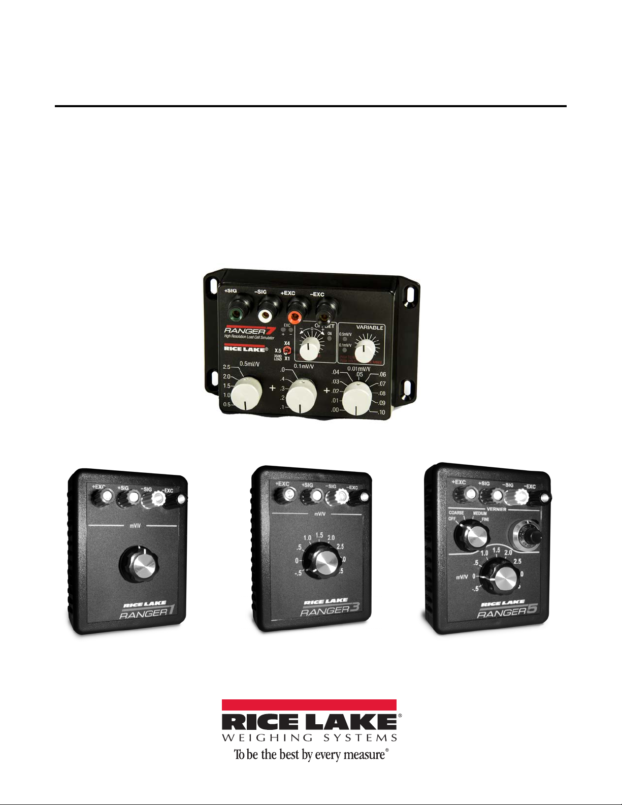
1.0 Introduction
The Rice Lake Weighing Systems Ranger load cell simulators are precision instruments designed to provide
millivolt level signals for testing, calibration and troubleshooting strain gage instrumentation and systems.
Accuracy and stability are obtained through the use of a “Star Bridge” circuit comprised of four temperature stable,
precision resistors.
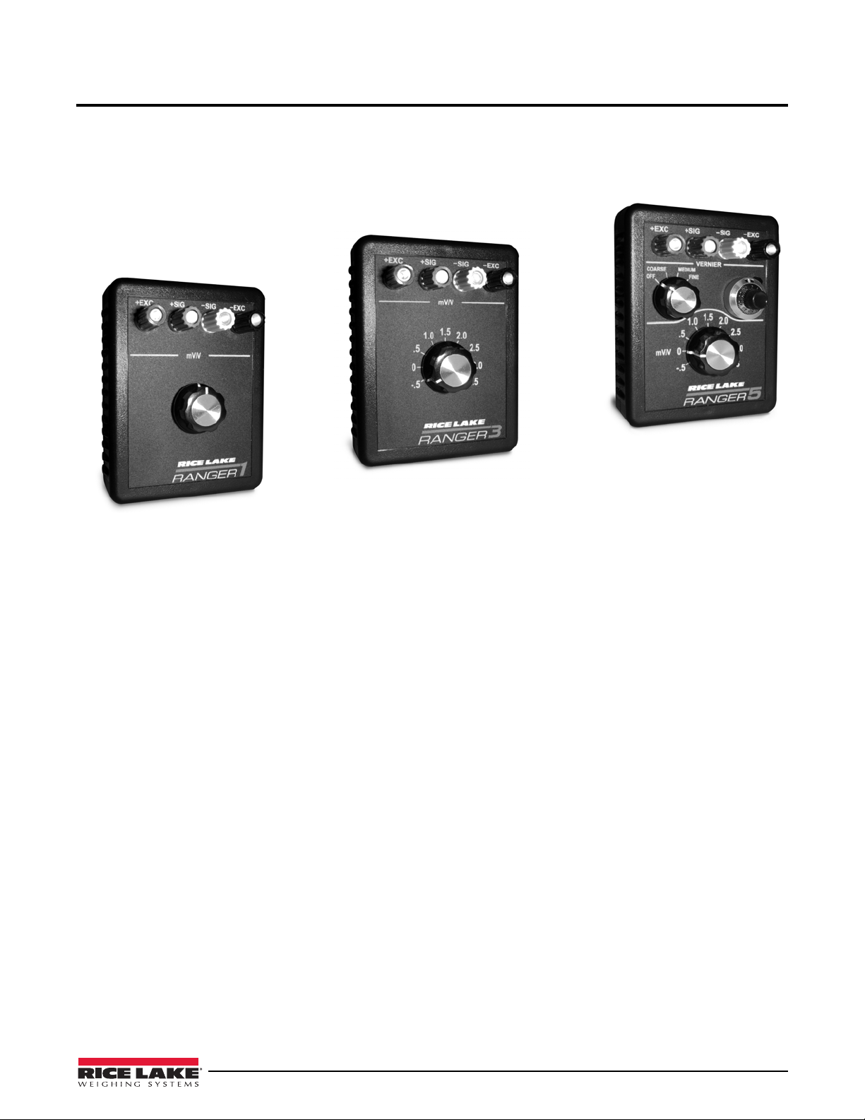
Rice Lake Weighing Systems offers four models of the Ranger Series S
imulators.
Figure 1-1. Ranger 1, 3 and 5 Simulators
Features
Ranger 1:
• Bridge impedance of 700 ohms
• 10-turn continuously variable output from 0 to
Ranger 3:
• Bridge impedance of 350 ohms
• Nine calibrated outputs - eight 0.5 mV/V steps from -0.5
step. The -0.5 and +4.5 mV/V settings are useful for performing A/D offset and gain calibrations in Rice
Lake indicators.
Ranger 5:
• This has the same features as the Ranger 3 with the addition of a 3-range, 10-turn locking vernier
These three Ranger Series Simulators connect
accept standard banana plugs or up to 14 gauge wire.
using binding posts color coded to the ISA S37.8 standard, and will
3 mV/V.
mV/V to 3.0 mV/V and an additional +4.5 mV/V
.
Introduction 1
Page 6

0.5mV/V
ZERO
0.01mV/V
0.1mV/V
+EXC –EXC+SIG –SIG
X4
X1
X.5
.04
.03
.02
.01
.00
.06
.07
.08
.09
.10
.05
.4
.3
.2
.1
.0
2.5
2.0
1.5
1.0
0.5
0.0
+ –
EXC
.0
PUSH TO ENABLE
HOLD TO CHANGE RANGE
0.5mV/V
VARIABLE
0.1mV/V
PUSH TO ENABLE
±25μV/V
OFFSET
ON
+
–
High Resolution Load Cell Simulator
Figure 1-2. Ranger 7 Simulator
Ranger 7:
• Load Impedance: Three settings by toggl
e switch. X0.5 =700, X1 = 350 (1 standard Load Cell), X4= 87.5
(4 Load Cell Platform).
• Output Range: 0-3mV/V in, 0.01mV/V steps (300 precision fixed steps)
This simulator comes with Type 2758 (by Low Thermal Electronics Inc.) precision gold plated low thermal EMF
5-w
ay binding posts for highest accuracy. Standard banana jacks at 0.75” pitch, or up to 14 AWG wire.
2 Ranger Series Operation Guide
Page 7

2.0 Ranger Simulators 1, 3 and 5 Operation
1
2
3
4
5
6
7
Note
To get the most out of the simulator, remember the following:
• Dampness, water, or other contamina
terminals. Keep the face and the terminals clean and dry when using the Ranger Series simulator.
• The binding posts are heavily plated, but should some c
use the unit.
• If the simulator has been at an unusual temperature environment for many hours (i.e., left in a truck during
winter
or summer), allow several minutes for the unit to stabilize to the ambient temperature of the scale
before using.
• Excitation voltage should not exceed 15 volts DC or AC (RMS). Higher voltages w
and possibly damage your simulator.
• When using the Ranger 5 simulator for testing stability or drift, or when r
the vernier range select switch is in the Off position.
The vernier is included as a diagnostic and setup tool only.
nts on the face of the simulator can cause leakage current between
orrosion occur, clean the posts before attempting to
ill degrade the accuracy
ecalibrating an indicator, make sure
Figure 2-1. Ranger 5 Control Location
1. Vernier Range Selector
OFF: Rotary Selector value
FINE: Rotary Selector value -0.02 mV/V
MEDIUM: Rotary Selector value -0.05 mV/V
COARSE: Rotary Selector value -0.12 mV/V
2. Locking Vernier Dial: 10-turn adjustment of selected ranges listed above
3. Rotary Selector: Fixed calibration steps of 0.5 mV/V from -0.5 t
to +0.5 mV/V
to +1.5 mV/V
to +3.0 mV/V
o 3.0 mV/V + 1.5mV/V step to 4.5 mV/V
4. +Excitation Input terminal post
5. +Signal Output terminal post
6. -Signal Output terminal post
7. -Excitation Output terminal post
Ranger Simulators 1, 3 and 5 Operation 3
Page 8

2.1 Sample Calculations
A Ranger simulator may be used to perform calibration of scale systems prior to installation, or test installations
prior to installation. These are NOT procedures that can be used to certify a scale, but they will provide calibration
results satisfactory for most process weigh scales. Checking the scale calibration with known weights, or product
substitution (with a verified value) is recommended.
Using a simulator, digital voltmeter, and calculator to calibrate a scale
The following tools are required:
•Ranger simulator
• Digital voltmeter (4 digit minimum, 5 digit recommended)
• Calculator
Use the following steps to calibrate a scale using a simulator, digital voltmeter and calculator.
1. Millivolt Output Average Calculation:
If load cell calibration certificates are available for the system load cells, add the full scale millivolt output
values, and divide the sum by the number of load cells in the system.
Example: 2.997 + 3.002 + 2.995 + 2.999 = 11.993 / 4 = 2.99825 mV
If the load cell calibration certificates are not available, the nominal full scale millivolt output of the load
cells is used as the average millivolt output (2mV/V or 3mV/V most common).
Unless the system load cells vary significantly from the nominal value, the calibration results will be very
similar.
2. With your digital volt meter in the volts setting, measure the excitation voltage at the junction box home
run cable +/- excitation connections, and record the value.
3. Full Scale Output Signal Calculation:
Multiply the millivolt output average value from step 1, by the excitation voltage value from step 2.
Example: 2.99825 x 9.9875 = 29.945 mV.
This is the full scale millivolt output of the scale at the total load cell capacity (individual load cell capacity
x the number of load cells in the scale).
4. Total Load Cell Capacity:
Multiply the individual load cell capacity by the number of load cells in the system.
Example: (10,000 lb x 4 = 40,000 lb) 40,000 lb is the Total load cell capacity.
5. Signal per Scale Division:
Divide the total load cell capacity from step 4 by the scale resolution value (if the scale is to be calibrated
to 25,000 x 5 lb, the scale resolution value is 5 lb). 40,000 / 5 = 8,000. This is the number of divisions over
the total load cell capacity. Divide the full scale millivolt output value from step 3 by this value.
Example: (29.945 mV / 8,000 = 0.003743 mV) this is the signal per division (signal change for each
5 lb scale change, based on the example).
6. Span Range Signal Calculation:
Multiply the signal per division value from step 5 by the number of divisions over the calibrated range of
the scale (25,000 lb / 5 - 5000 x 0.003743 - 18.715625 mV). This is the span signal range to which the
scale will be calibrated.
7. With the scale empty, perform the normal ZERO calibration procedure (refer to the indicator manual).
Enter the calibrated scale capacity as the SPAN value (25,000 in the example in Step 6).
8. With your digital volt meter set to the millivolt range, measure the signal at the junction box home run
cable +/- signal connections, and record the value. this is the scale millivolt output value at calibrated
ZERO. Example: 4.245 mV (this is a random value selected for this exercise).
9. Span Calibration Signal Calculation: Add the calibrated ZERO millivolt value from Step 8 to the Span
Range value from Step 6 (18.715625 + 4.245 = 22.960). This is the Span Calibration Signal value.
4 Ranger Simulator Operation Guide
Page 9

10. Power down the digital weight indicator and disconnect the home run cable at the junction box. Connect
the home run cable to your scale simulator. Reapply power to the digital weight indicator. With your digital
volt meter set to the millivolt range, measure across the +/- signal terminals of the scale simulator, and
adjust the simulator until your volt meter value equals the Span Calibration Signal value calculated in
Step 9.
11. Perform the indicator SPAN calibration procedure (refer to the indicator manual). The load cell simulator
adjusted to the value from Step 9, is simulating the test weight load at the calibrated capacity (25,000 lb in
this example).
12. Return the indicator to the normal weigh mode. Power down the indicator, disconnect the simulator, and
reconnect the home run cable at the junction box. Reapply power to the indicator. Provided that the scale is
still empty, the indicator should read 0 lb Re-zero the scale if necessary. The scale is now calibrated.
Pre-Calibrating an Indicator Using a Simulator (Ranger 3 and 5 Only)
For this example we will pre-calibrate an indicator that will be connected to a single load cell application. The cell
capacity is 500 lbs, rated output is 2 mV/V, and the actual output on the cell’s certificate is 2.002 mV/V.
1. Calculate the units per millivolt:
Divide the load cell capacity (500) by the actual output (2.002) to get 249.7502 lbs per millivolt.
2. Calculate the actual weight expected for the 2 mV/V setting on your simulator by multiplying the value
from Step 1 (249.7502) with the mV/V setting of the simulator and get 499.5005.
3. Connect the simulator to the weight indicator and allow the indicator to warm up for 5-10 minutes.
4. Set the simulator mV/V selector switch to 0 (vernier off) and calibrate for Zero.
5. Set the simulator mV/V selector switch to the setting used in Step 2 (for this example, 2 mV/V).
6. Calibrate the span of the indicator using the actual weight expected value from Step 2 as the weight value
(WVal for most Rice Lake indicators), 499.5005 lb for this example.
7. When the indicator is connected to the actual scale, use the calibration REZERO function to account for
any deadload on the load cell.
Ranger Simulators 1, 3 and 5 Operation 5
Page 10

3.0 Ranger 7 Simulator Operation
0.5mV/V
ZERO
0.01mV/V
0.1mV/V
+EXC –EXC+SIG –SIG
X4
X1
X.5
.04
.03
.02
.01
.00
.06
.07
.08
.09
.10
.05
.4
.3
.2
.1
.0
2.5
2.0
1.5
1.0
0.5
0.0
+ –
EXC
.0
PUSH TO ENABLE
HOLD TO CHANGE RANGE
0.5mV/V
VARIABLE
0.1mV/V
PUSH TO ENABLE
±25μV/V
OFFSET
ON
+
–
High Resolution Load Cell Simulator
Switch One Switch Two Switch Three
Variable Switch
Offset Switch
EXC LEDs
Toggle Switch
Binding Posts
Note
Note
Figure 3-1. Ranger 7 Simulator
3.1 Standard Operation
3.1.1 Switches
The three switches across the bottom front face of the Ranger 7 work together up to 3 mV/V.
• Switch one maximum = 2.5
• Switch two maximum = .4 (has two .0 settings, they
• Switch three maximum = .10 (
ZERO position puts the mV/V output setting to zero regardless of the other
switch settings)
When switch three is set to ZERO, only the offset switch can vary the output in this setting. This allows an easy
way to check AZM settings as well as quick return
Example:
Switch one is set to 2mV/V, switch two is set to 0.0 and switch three
ZERO position, the output will instantly jump between 2mV/V and 0mV/V.
are identical settings)
to zero for time testing.
is set to .00. By setting switch three to the
3.1.2 Toggle Switch Load Control
3.1.3 EXC LEDs
An indication of excitation voltage presence, indicating the polarity of the excitation to aid in proper wiring.
If both LEDs are lit, it indicates AC excitation.
3.1.4 To Simulate a Larger Load
6 Ranger Simulator Operation Guide
• X1 mode – load is 350Ω, equivalent to a single standard load cell
•
X.5 mode – load is 700Ω, providing a lightly loaded system
•
X4 mode – load is 87.5Ω which is equivalent to a 4 load cell platform scale
The Ranger 7 works with all polarities of excitation as long as the peak or DC voltage is between 3.5V and 12V.
1. Place a power resistor between the EXC+ and EXC- binding posts. Use a 22Ω 7.5W resistor for excitation
up to 10V.
2. Put the load switch in the
desired load.
X.5 position. Calculate the required resistance using R=(700 x X)/(700 - X). X is the
Page 11

3. Calculate the required wattage using ((ExcV x ExcV)/R) x 1.5. Use the next highest wattage value.
Note
In a 16 load cell example, the 22 ohm resistor will have to
If the excitation voltage is higher, a higher wattage resist
To achieve highest performance, low thermal EMF wiring and components are required. A manufacturer of the
binding posts is Low Thermal Electronics, they can provide low thermal
posts.
be rated at least 6.8W. 7W is a common size.
or will be required.
spade lugs to mate to the binding
3.2 Offset
Offset will add or subtract up to ±25µV/V (±0.025mV/V).
1. Press the
Offset switch to enable the function.
2. Rotate the knob to the desired setting.
3. Press the
Offset switch again to disable the function.
3.3 Variable
Press the Variable switch to enable/disable the function.
There are two ranges of variable mV/V.
3.3.1 Coarse Control Range
The range is 0 to 500µV/V (0 to 0.5mV/V) plus the setting of the far left knob.
This range disables and replaces the center 0.1mV/V and right 0.01mV/V switches. The variable range
one plus the variable switch and will range from 0 to 0.5mV/V.
1. Press and release the
Variable switch to enable the function.
is Switch
2. Adjust the setting as required.
3. Press and release the
Variable switch again to disable the function.
3.3.2 Fine Variable Setting
In the fine setting, the variable switch disables and replaces the far right 0.01mV/V switch. So the variable range is
switch one plus switch two plus the variable switch, it will range from 0 to 0.1mV/V.
1. Press and hold the variable switch (you must start from
2. When the second LED (labeled 0.1mV/V) lights rel
Off).
ease the switch pushbutton.
Ranger 7 Simulator Operation 7
Page 12

4.0 Troubleshooting With a Simulator
The most common use for load cell simulators is diagnosing problems with electronic scale indicators or with a
strain gauge load cell scale installation. Many problems in measurement systems involve drift or other situations,
which are not repeatable. A simulator gives a fixed point from which all other system components can be judged to
be properly working. Below are some tips for using a Ranger Series simulator as a troubleshooting tool.
Is the indicator working correctly?
• Connect the simulator directly to the indicator and see if the indicator is operational.
• If the indicator’s display is drifting, or not what is expected, there may be a problem with the analog input
stage, the excitation supply, or the sense circuitry.
• Several simulators may be connected in parallel to effectively “load” down the excitation supply circuits to
check for correct operation with multiple load cells.
What is the number of display graduations with the simulator output set to different settings?
• By measuring the excitation voltage and multiplying by the setting on the simulator, the actual input signal to
the indicator can be accurately calculated.
• This may help determine whether or not there is sufficient gain and low signal sensitivity in the indicator for
operation with low output systems.
• The linearity of the indicator may also be checked this way.
• If after installation and calibration of a system, a simulator is substituted for the load cells and the value
displayed for the zero and one of the other calibrated settings (i.e., 1 mV/V) are recorded, later recalibration
or repair can be greatly simplified by direct comparison of the displayed value with the previously recorded
values.
Does the displayed value change or start drifting, after other equipment or load cells are connected?
• Problems with transient protection boards, junction boxes, auxiliary power supplies and load cell cables can
be tracked down step by step by starting at the indicator and moving the simulator(s) down the line to the
load cells.
• When testing a portion of the system, make sure all other un-tested parts of the system are not connected.
When using the vernier (Ranger 1 or 5), do setpoint outputs and the display change as expected?
• Problems with output boards, setpoint routines and batching equipment can easily be found by using the
variable vernier output of the Ranger 1 or 5 to simulate the effect of changing amounts of weight on the
system.
• In addition, inappropriate filtering settings that may not be apparent normally, may sometimes be identified
this way.
Are the load cells working properly?
• By substituting a simulator for each load cell in a system, drifting cells, unevenly loaded cells, or other cell
related problems can be identified.
• After installation of a simulator in place of a load cell, note the zero and span readings for the simulator in
that particular position (vernier turned off).
• If the zero and span readings are substantially different when the simulator is moved from cell to cell, and
these differences are not consistent with the design of the scale, suspect cells can be easily identified.
8 Ranger Simulator Operation Guide
Page 13

5.0 Product Specifications
Impedance: Ranger 1: 700 ohms nominal
Output Ranges: Ranger 1: 0 to 3 mV/V continuously variable
Vernier (Ranger 5 only): Fine: -0.02 to +0.5 mV/V of selected range
Accuracy (Ranger 3 & 5): +/-0.02% of selected range
Zero Offset (Ranger 3 & 5): Ranger 1: +0.005 mV/V Max
Normal Operating Temp: 14°F to 104°F (-10C to + 40C)
Temperature Coefficient: Ranger 1: 100 ppm/ C
Excitation Voltage: 15 VDC/AC Max
Unit Size: 3.5”W x 4.5”L x 2.2”D
Weight: 0.55 lb (Ranger 5)
Enclosure: Flame retardant ABS plastic
Ranger 3 & 5: 350 ohms nominal
Ranger 3 & 5: -0.5, 0, 0.5, 1.0, 1.5, 2.0, 2.5, 3.0, and 4.5 mV/V
Medium: -0.05 to +1.5 mV/V of selected range
Course: -0.12 to +3.0 mV/V of selected range
Ranger 3 & 5: +0.0005 mV/V Max
Ranger 3 & 5: 5 ppm/ C
Ranger 7
Load Impedance: Three settings by toggle switch.
Output Range: 0-3mV/V in .01mV/V steps (300 precision fixed steps)
Switchable Vernier: Two Ranges
Switchable Offset: Off or switch setting ±25V/V. Enabled by pressing the switch.
Accuracy: ±0.01% + 1V of selected range
Zero Setting: Position Zero returns the output to zero regardless of the switch settings. Offset setting remains
Zero Offset: ±0.0005 mV/V
Initial Zero Offset: ±2µV
Normal Operating Temp: 14°F to 104°F (-10°C to +40°C), accuracy specified at 23°C ±5°C
Temperature Coefficient: 5ppm/°C
Excitation Voltage: 3.5V to 12V unipolar. ±1.75 to ±6 Bipolar
LED Annunciators: EXC+ – normal Excitation Polarity.
Binding Posts: Type 2758 (by Low Thermal Electronics Inc.) precision gold plated low thermal EMF 5-way binding
X0.5 =700 ohms
X1 = 350 ohms (1standard load cell)
X4= 87.5 ohms (4 load cell platform)
Range 1 is equal to the 0.5mV/V switch plus 0 -0.5mV/V.
Range 2 is equal to the 0.5mV/V switch plus the 0.1mV/V switch plus 0-0.1mV/V. Enabled by
pressing the switch.
constant (if enabled).
EXC– – reverse Excitation Polarity. Both are on with AC Excitation.
OFFSET ON – the offset pot is enabled.
0.5mV/V – the variable pot is enabled with a range of 0 to 0.5mV/V plus the 0.5mV/V Rotary Switch
setting.
0.1mV/V – the variable pot is enabled with a range of 0 to 0.1mV/V plus the 0.5mV/V and 0.1mV/V
switch settings.
posts for highest accuracy. Standard banana jacks at 0.75” Pitch, or up to 14 AWG wire.
Product Specifications 9
Page 14

Limited Warranty
Rice Lake Weighing Systems (RLWS) warrants that all RLWS equipment and systems properly installed by a Distributor or Original Equipment Manufacturer (OEM) will operate per written specifications as confirmed by the
Distributor/OEM and accepted by RLWS. All systems and components are warranted against defects in materials
and workmanship for one year.
RLWS warrants that the equipment sold hereunder will conform to the current written specifications authorized by
RLWS. RLWS warrants the equipment against faulty workmanship and defective materials. If any equipment fails
to conform to these warranties, RLWS will, at its option, repair or replace such goods returned within the warranty
period subject to the following conditions:
• Upon discovery by Buyer of such nonconformity, RLWS will be given prompt written notice with a detailed
explanation of the alleged deficiencies.
• Individual electronic components returned to RLWS for warranty purposes must be packaged to prevent elec-
trostatic discharge (ESD) damage in shipment. Packaging requirements are listed in a publication, Protecting
Your Components From Static Damage in Shipment, available from RLWS Equipment Return Department.
• Examination of such equipment by RLWS confirms that the nonconformity actually exists, and was not caused
by accident, misuse, neglect, alteration, improper installation, improper repair or improper testing; RLWS shall
be the sole judge of all alleged non-conformities.
• Such equipment has not been modified, altered, or changed by any person other than RLWS or its duly authorized repair agents.
• RLWS will have a reasonable time to repair or replace the defective equipment. Buyer is responsible for shipping charges both ways.
• In no event will RLWS be responsible for travel time or on-location repairs, including assembly or disassembly
of equipment, nor will RLWS be liable for the cost of any repairs made by others.
THESE WARRANTIES EXCLUDE ALL OTHER WARRANTIES, EXPRESSED OR IMPLIED, INCLUDING WITHOUT LIM-
ITATION WARRANTIES OF MERCHANTABILITY OR FITNESS FOR A PARTICULAR PURPOSE. NEITHER RLWS NOR
DISTRIBUTOR WILL, IN ANY EVENT, BE LIABLE FOR INCIDENTAL OR CONSEQUENTIAL DAMAGES.
RLWS AND BUYER AGREE THAT RLWS’ SOLE AND EXCLUSIVE LIABILITY HEREUNDER IS LIMITED TO REPAIR
OR REPLACEMENT OF SUCH GOODS. IN ACCEPTING THIS WARRANTY, THE BUYER WAIVES ANY AND ALL OTHER
CLAIMS TO WARRANTY.
SHOULD THE SELLER BE OTHER THAN RLWS, THE BUYER AGREES TO LOOK ONLY TO THE SELLER FOR WAR-
RANTY CLAIMS.
NO TERMS, CONDITIONS, UNDERSTANDING, OR AGREEMENTS PURPORTING TO MODIFY THE TERMS OF THIS
WARRANTY SHALL HAVE ANY LEGAL EFFECT UNLESS MADE IN WRITING AND SIGNED BY A CORPORATE OFFI-
CER OF RLWS AND THE BUYER.
© Rice Lake Weighing Systems, Inc. Rice Lake, WI USA. All Rights Reserved.
RICE LAKE WEIGHING SYSTEMS • 230 WEST COLEMAN STREET • RICE LAKE, WISCONSIN 54868 • USA
10 Ranger Simulator Operation Guide
Page 15

Page 16

230 W. Coleman St. • Rice Lake, WI 54868 • USA
U.S. 800-472-6703 • Canada/Mexico 800-321-6703 • International 715-234-9171 • Europe +31 (0) 88 2349171
www.ricelake.com www.ricelake.mx www.ricelake.eu www.ricelake.co.in m.ricelake.com
© Rice Lake Weighing Systems 02/2014 PN 105354 Rev A
 Loading...