

Page 1

SCT Weight Transmitter
10 Series
Installation & Operator’s Manual
131129 Rev A
Page 2

Page 3

Contents
Technical training seminars are available through Rice Lake Weighing Systems.
Course descriptions and dates can be viewed at www.ricelake.com/training
or obtained by calling 715-234-9171 and asking for the training department.
1.0 Introduction............................................................................ 1
1.1 Safety. . . . . . . . . . . . . . . . . . . . . . . . . . . . . . . . . . . . . . . . . . . . . 1
1.1.1 Safety Symbol Definitions: . . . . . . . . . . . . . . . . . . . . . . . . . . . . . . . . . 1
1.1.2 Safety Precautions . . . . . . . . . . . . . . . . . . . . . . . . . . . . . . . . . . . . . . . 1
1.1.3 Equipment Recommendations . . . . . . . . . . . . . . . . . . . . . . . . . . . . . . 2
1.1.4 Correct Installation Of Weighing Instruments . . . . . . . . . . . . . . . . . . . 2
1.1.5 Correct Installation Of The Load Cells. . . . . . . . . . . . . . . . . . . . . . . . . 2
1.2 Load Cells . . . . . . . . . . . . . . . . . . . . . . . . . . . . . . . . . . . . . . . . . 3
1.2.1 Load Cell Input Test (Quick Access) . . . . . . . . . . . . . . . . . . . . . . . . . . 3
1.2.2 Load Cell Testing . . . . . . . . . . . . . . . . . . . . . . . . . . . . . . . . . . . . . . . . 4
1.3 Specifications . . . . . . . . . . . . . . . . . . . . . . . . . . . . . . . . . . . . . . 4
1.4 Electrical Connections . . . . . . . . . . . . . . . . . . . . . . . . . . . . . . . 6
1.5 LED and Key Functions . . . . . . . . . . . . . . . . . . . . . . . . . . . . . . 7
1.6 Instrument Commissioning . . . . . . . . . . . . . . . . . . . . . . . . . . . 8
1.6.1 If The Instrument Has Not Been Calibrated. . . . . . . . . . . . . . . . . . . . . 8
2.0 Configuration ......................................................................... 9
2.1 Calibration . . . . . . . . . . . . . . . . . . . . . . . . . . . . . . . . . . . . . . . . 11
2.1.1 Theoretical Calibration . . . . . . . . . . . . . . . . . . . . . . . . . . . . . . . . . . . 14
2.1.2 Maximum Capacity (NASS ) . . . . . . . . . . . . . . . . . . . . . . . . . . . . . . . 14
2.1.3 Zero Setting . . . . . . . . . . . . . . . . . . . . . . . . . . . . . . . . . . . . . . . . . . . 15
2.1.4 Zero Value Manual Entry. . . . . . . . . . . . . . . . . . . . . . . . . . . . . . . . . . 15
2.1.5 Weight (Span) Calibration (With Test Weights) . . . . . . . . . . . . . . . . . 16
2.1.6 Setting Units of Measure . . . . . . . . . . . . . . . . . . . . . . . . . . . . . . . . . 17
2.1.7 Display Coefficient . . . . . . . . . . . . . . . . . . . . . . . . . . . . . . . . . . . . . . 17
2.2 Filter On The Weight . . . . . . . . . . . . . . . . . . . . . . . . . . . . . . . . 19
2.3 Zero Parameters . . . . . . . . . . . . . . . . . . . . . . . . . . . . . . . . . . . 20
2.4 Analog Output . . . . . . . . . . . . . . . . . . . . . . . . . . . . . . . . . . . . . 21
2.5 Serial Communication Settings . . . . . . . . . . . . . . . . . . . . . . . 23
2.5.1 RS-485 Serial Communication . . . . . . . . . . . . . . . . . . . . . . . . . . . . . 25
2.6 Outputs And Inputs Configuration . . . . . . . . . . . . . . . . . . . . . 26
2.7 Test . . . . . . . . . . . . . . . . . . . . . . . . . . . . . . . . . . . . . . . . . . . . . 28
2.8 Setpoints Programming . . . . . . . . . . . . . . . . . . . . . . . . . . . . . 29
2.9 Reserved For The Installer . . . . . . . . . . . . . . . . . . . . . . . . . . . 30
2.9.1 Default Scale . . . . . . . . . . . . . . . . . . . . . . . . . . . . . . . . . . . . . . . . . . 30
2.9.2 Program Selection - Reverse:. . . . . . . . . . . . . . . . . . . . . . . . . . . . . . 30
2.9.3 Keypad Or Display Locking . . . . . . . . . . . . . . . . . . . . . . . . . . . . . . . 31
© Rice Lake Weighing Systems. All rights reserved. Printed in the United States of America.
Specifications subject to change without notice.
Rice Lake Weighing Systems is an ISO 9001 registered company.
December 27, 2013
Page 4

Rice Lake continually offers web-based video training on a growing selection
of product-related topics at no cost. Visit www.ricelake.com/webinars.
3.0 Operation.............................................................................. 32
3.1 Semi-Automatic Tare (Net/Gross) . . . . . . . . . . . . . . . . . . . . . 32
3.2 Preset Tare (Subtractive Tare Device) . . . . . . . . . . . . . . . . . . 32
3.3 Semi-Automatic Zero (Weight Zero-setting For Small Variations)
33
3.4 Peak. . . . . . . . . . . . . . . . . . . . . . . . . . . . . . . . . . . . . . . . . . . . . 33
3.5 Alarms . . . . . . . . . . . . . . . . . . . . . . . . . . . . . . . . . . . . . . . . . . . 33
3.6 Modbus-RTU Protocol . . . . . . . . . . . . . . . . . . . . . . . . . . . . . . 34
3.7 ASCII Bidirectional Protocol. . . . . . . . . . . . . . . . . . . . . . . . . . 41
3.8 Fast Continuous Transmission Protocol . . . . . . . . . . . . . . . . 46
3.9 Continuous Transmission Protocol To Remote Displays . . . 46
3.10 Communication Examples . . . . . . . . . . . . . . . . . . . . . . . . . . 48
SCT Weight Transmitter Limited Warranty ................................... 51
For More Information .................................................................... 53
ii SCT Weight Transmitter Operator’s Manual
Page 5
1.0 Introduction
WARNING
Important
WARNING
1.1 Safety
1.1.1 Safety Symbol Definitions:
Indicates a potentially hazardous situation that, if not avoided
could result in death or serious injury, and includes hazards
that are exposed when guards are removed.
Indicates information about procedures that, if not observed,
could result in damage to equipment or corruption to and
loss of data.
1.1.2 Safety Precautions
Do not operate or work on this equipment unless you have
read and understand the instructions and warnings in this
manual. Contact any Rice Lake Weighing System dealer for
replacement manuals. Proper care is your responsibility.
Failure to heed may result in serious injury or death.
Risk of electrical shock. No user serviceable parts. Refer to qualified service
personnel for service.
The unit has no power switch, to completely remove D/C power from the unit,
disconnect the D/C power cable from the main socket.
DO NOT allow minors (children) or inexperienced persons to operate this unit.
DO NOT operate without all shields and guards in place.
DO NOT use for purposes other then weighing applications.
DO NOT place fingers into slots or possible pinch points.
DO NOT use this product if any of the components are cracked.
DO NOT make alterations or modifications to the unit.
DO NOT remove or obscure warning labels.
DO NOT use near water.
Introduction 1
Page 6

1.1.3 Equipment Recommendations
Important
Failure to follow the installation recommendations will be
considered a misuse of the equipment
To Avoid Equipment Damage
• Keep away from heat sources and direct sunlight.
• Protect the instrument from rain.
• Do not wash, dip in water or spill liquid on the instrument.
• Do not use solvents to clean the instrument.
• Do not install in areas subject to explosion hazard.
1.1.4 Correct Installation Of Weighing Instruments
• The terminals indicated on the instrument’s wiring diagram to be connected
to earth must have the same potential as the scale structure (ground). If you
are unable to ensure this condition, connect a ground wire between the
instrument and the scale structure.
• The load cell cable must be run separately to the instrument input and not
share a conduit with other cables. A shielded connection must be continuous
without a splice.
• Use “RC” filters (quench-arcs) on the instrument-driven solenoid valve and
remote control switch coils.
• Avoid electrical noise in the instrument panel; if inevitable, use special
filters or sheet metal partitions to isolate.
• The panel installer must provide electrical protection for the instruments
(fuses, door lock switch, etc.).
• It is advisable to leave equipment always switched on to prevent the
formation of condensation.
• Maximum Cable Lengths:
- RS-485: 1000 metres with AWG24, shielded and twisted cables
- RS-232: 15 metres for baud rates up to 19200
1.1.5 Correct Installation Of The Load Cells
Installing Load Cells:
The load cells must be placed on rigid, stable structures within .5% of plumb and
level. It is important to use mounting modules for load cells to compensate for
misalignment of the support surfaces.
Protection Of The Load Cell Cable:
Use water-proof sheaths and joints in order to protect the cables of the load cells.
Mechanical Restraints (pipes, etc.):
When pipes are present, we recommend the use of hoses, flexible couplings and
rubber skirted joints. In case of rigid conduit and pipes, place the pipe support or
anchor bracket as far as possible from the weighed structure (at a distance at least
40 times the diameter of the pipe).
Welding:
Avoid welding with the load cells already installed. If this cannot be avoided,
place the welder ground clamp close to the required welding point to prevent
sending current through the load cell body.
2 SCT Weight Transmitter Operator’s Manual
Page 7
Windy Conditions - Shocks - Vibrations:
Uses ground plate
to continue ground.
Uses structure to continue ground.
PRINT
MENU
0
ESC
The use of weigh modules is strongly recommended for all load cells to
compensate for misalignment of the support surfaces. The system designer must
ensure that the scale is protected against lateral shifting and tipping relating to
shocks and vibration, windy conditions, seismic conditions and stability of the
support structure.
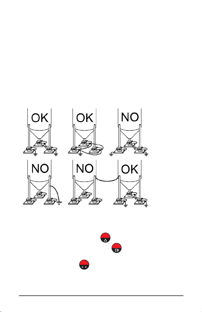
Grounding The Weighed Structure:
By means of a 10ga solid or braided wire or braided grounding strap, connect the
load cell upper support plate with the lower support plate, then connect all the
lower plates to a single earth ground. Once installed electrostatic charges
accumulated are discharged to the ground without going through or damaging the
load cells. Failure to implement a proper grounding system might not affect the
operation of the weighing system; this, however, does not rule out the possibility
that the load cells and connected instrument may become damaged by ESD. It is
forbidden to ensure grounding system continuity by using metal parts contained
in the weighed structure.(see Figure 1-1.)
1.2 Load Cells
1.2.1 Load Cell Input Test (Quick Access)
1. From the weight display, press for 3 seconds.
2. The display will read NU-CEL. Press .
3. The response signal of the load cell is displayed, expressed in mV with
four decimals. Press three times to exit set-up mode.
Figure 1-1. Installation Recommendations
Introduction 3
Page 8
1.2.2 Load Cell Testing
Important
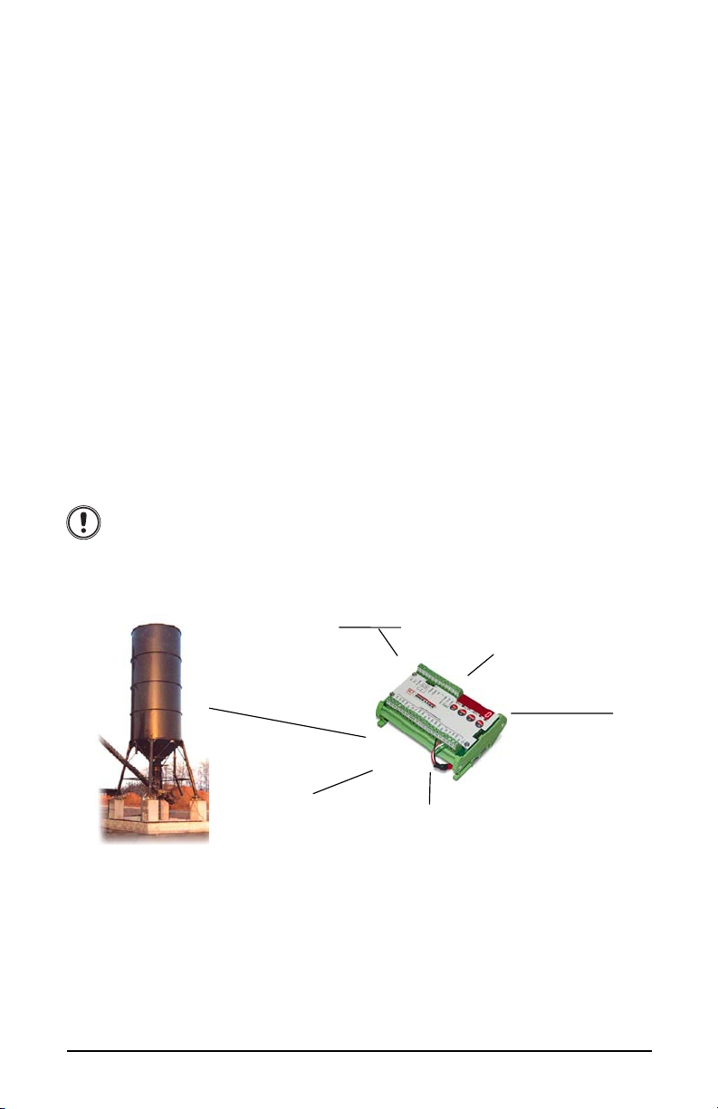
ANALOG OUTPUT
(Current and Voltage)
PLC
PLC or FIELD SIGNALS
2 DIGITAL INPUTS
(Optoisolated,
Externally supplied)
2 RELAY
MAX 8 LOAD CELLS IN
PARALLEL
RS-485
RS-232
Modbus RTU
SERIAL PORT
DC power
supplier
(12-24 Volt )
Load Cell Resistance Measurement (Use A Digital Multimeter):
• Disconnect the load cells from the instrument and check that there is no
moisture in the load cell junction box caused by condensation or water
infiltration. If so, drain the system or replace it if necessary.
• The value between the positive signal wire and the negative signal wire must
be equal or similar to the one indicated in the load cell data sheet (output
resistance).
• The value between the positive excitation wire and the negative excitation
wire must be equal or similar to the one indicated in the load cell data sheet
(input resistance).
• The insulation value between the shield and any other load cell wire and
between any other load cell wire and the body of the load cell must be higher
than 20 Mohm (mega ohms).
Load Cell Voltage Measurement (Use A Digital Multimeter):
• Remove weight of scale from load cell to be tested.
• Make sure that the excitation wires of the load cell connected to the
instrument is 5 Vdc +/- 3%.
• Measure the millivolt signal between the positive and the negative signal
wires by directly connecting them to the multi-meter, and make sure it reads
between 0 and 0.5 mV (thousandths of a Volt).
• Apply load to the load cell and make sure that there is a signal increment.
If one of the above conditions is not met, please contact the
technical assistance service.
1.3 Specifications
• Weight indicator and transmitter for Omega/DIN rail mounting suitable for
back panel; space saving vertical shape. Six-digit semi alphanumeric display
(18mm h), 7 segment. Four-key keyboard. Dimensions: 25x115x120 mm.
• Displays the gross weight; with an external contact capable of remote
zeroing and gross/net switching.
• IP67 box version (dimensions: 170x140x95mm). Four fixing holes diameter
4mm (center distance 122x152mm).
• Peak weight function.
4 SCT Weight Transmitter Operator’s Manual
Page 9

• Transmits the gross or net weight via opto-isolated analog output 16 bit,
current 0-20mA, 4-20mA or voltage 0-10V, 0-5V (±0V / ±5V by closing a
soldered jumper).
• Transmits the gross or net weight via RS-485 serial port, by means of
protocols:
- Modbus RTU
- ASCII bidirectional protocol
- Continuous transmission
Power Supply And Consumption (VDC) 12 - 24 VDC (standard)+/- 10% ; 5 W
No. Of Load Cells In Parallel and
Supply
Linearity / Analog Output Linearity < 0.01% F.S. ; < 0.01% F.S.
Thermal Drift / Analog Output Thermal
Drift
A/D Converter 24 bit (16.000.000 points)
Max Divisions (With Measurement
Range: +/-10mv = Sens. 2mv/v)
Measurement Range +/- 19.5 mV
Max Sensitivity Of Usable Load Cells +/-3mV/V
Max Conversions Per Second 80 conversions/second
Display Range - 999999 ; + 999999
No. of Decimals / Display Increments 0 - 4 / x 1 x 2 x 5 x 10 x 20 x 50 x 100
Digital Filter / Readings Per Second 0.080 – 7.5 sec / 5 - 80 Hz
Relay Logic Outputs N.2 - max 24 VAC ; 60mA
Logic Inputs N.2 - optoisolated 5 - 24 VDC PNP
Serial Ports RS-485 (RS-232)
Baud Rate 2400, 4800, 9600, 19200, 38400,
Humidity (Non Condensing) 85 %
Storage Temperature - 30°C + 80°C
Working Temperature - 20°C + 60°C
Optoisolated Analog Output 16 Bit -
65535 Divisions
max 8 ( 350 ohm ) ; 5VDC/120mA
< 0.0005 % F.S. /°C ; < 0.003 % F.S./°C
+/- 999999
115200
0-20 mA; 4-20 mA (max 300 ohm); 0-10
VDC; 0-5 VDC; +/- 10 VDC; +/- 5 VDC
(min 10 kohm).
Table 1-1. Technical Specifications
Introduction 5
Page 10
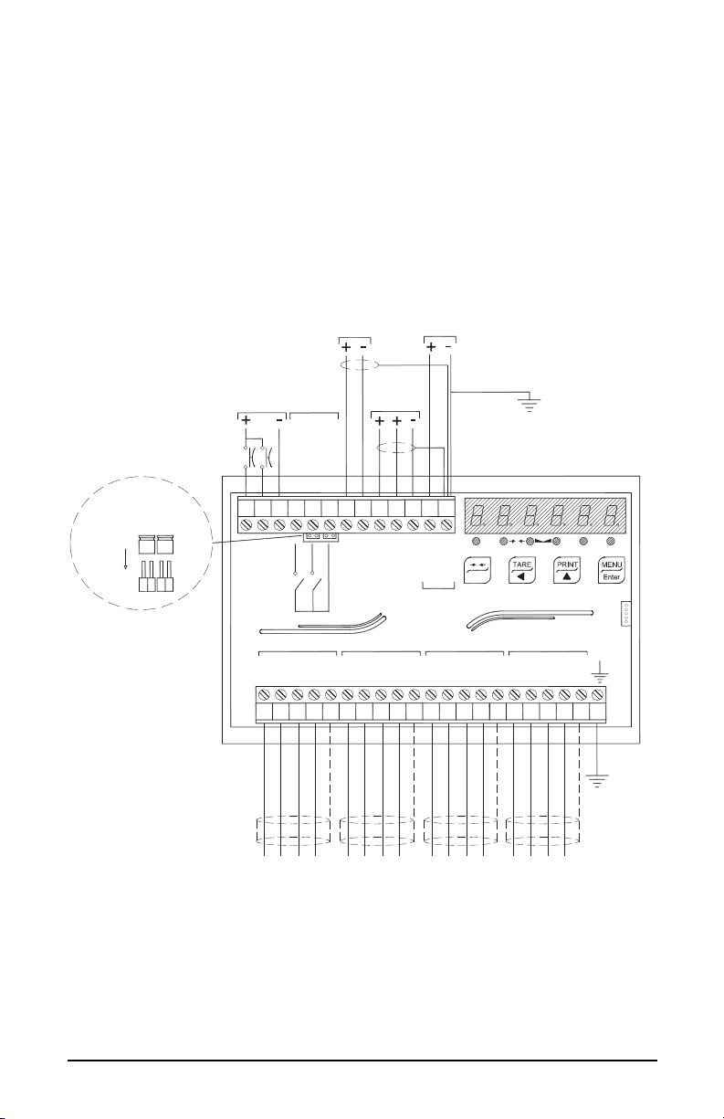
1.4 Electrical Connections
13123456789 111210
21
141516 17 18 19 20
SH
LOAD CELLS IN PARALLEL
IN1
IN2
IN COM
OUT1
OUT2
+ RS485
-
RS485
mA
V
mA-V COM
NET 0
kg
g
L
INPUTS
5-24Vdc
OUTPUTS
24Vdc
60mA
RS485
OUTPUT
12-24Vdc
ANALOG
RS485 termination
0
ESC
333130 322827252324 26 2922 34
+ 12-24
0 VDC
POWER
+ EX
-
EX
-
SIG
+ SIG
-
EX
+ EX
-
SIG
+ SIG
SH
-
EX
+ EX
-
SIG
+ SIG
SH
-
EX
+ EX
-
SIG
+ SIG
SH
J1
J2
SCT
Current output: max load 300 Ohm
Voltage output: min. load 10 kOhm
- EXCITATION
+ EXCITATION
- SIGNAL
+ SIGNAL
- EXCITATION
+ EXCITATION
- SIGNAL
+ SIGNAL
- EXCITATION
+ EXCITATION
- SIGNAL
+ SIGNAL
- EXCITATION
+ EXCITATION
- SIGNAL
+ SIGNAL
• It is recommended that the negative side of the power supply be grounded.
• It is possible to power up to eight 350 ohm load cells or sixteen 700 ohm
load cells.
• Connect terminal “0 VDC” to the RS-485 common of the connected
instruments in the event that these receive alternating current input or that
they have an opto-isolated RS-485.
• In case of an RS-485 network with several devices it is recommended to
activate the 120 ohm termination resistance on the two devices located at the
ends of the network, see Section 2.5.1 “RS-485 Serial Communication” on
page 25
2 outputs: configurable setpoints or remote output management via protocol.
2 inputs (Default: SEMI-AUTOMATIC ZERO input 1; NET/GROSS input
2): settable to have the following functions: SEMI-AUTOMATIC ZERO,
NET/GROSS, PEAK, or REMOTE CONTROL (see Section 2.6 “Outputs
And Inputs Configuration” on page 26).
6 SCT Weight Transmitter Operator’s Manual
Page 11
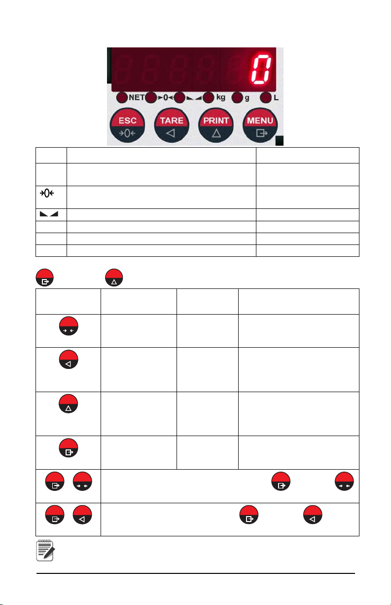
1.5 LED and Key Functions
MENU
PRINT
0
ESC
TARE
PRINT
MENU
MENU
0
ESC
MENU
0
ESC
MENU
TARE
MENU
TARE
Note
LED Main function Secondary function *
NET Net weight LED: net weight display (semi-
automatic tare or preset tare)
Zero LED (deviation from zero not more than +/-
0.25 divisions)
Stability LED LED lit: output 1 closed
kg Unit of measure: kg LED lit: output 2 closed
g Unit of measure: g No meaning
L Unit of measure:lb No meaning
* To activate the secondary LED function, during weight display press and hold
, then press .
Long press
Key Short press
(3 sec) Into menus
Zero Setting Cancel or return to previous
Escape
Captures Tare
Gross Net
Removes Tare
Net Gross
Scroll/
Backspace
mV load cell
test
Next/ Data
Entry
Setting setpoints
and hysteresis
Enter
LED lit: input 1 cosed
LED lit: input 2 closed
menu
Select figure to be modified or
return to previous menu item
Modify selected figure or go
to next menu item
Confirm or enter in submenu
+ Setting general parameters (press and hold then press
to enter set-up menu.
+ Setting preset tare (press and hold then press to enter
set-up menu.
The LEDs light up in sequence to indicate that a setting and not a
weight is being viewed.
Introduction 7
Page 12

1.6 Instrument Commissioning
Note
1. Plug power cord in to outlet to turn on indicator, the display shows in
sequence:
-“SU” followed by the software code (e.g.: SU S );
-- “r” followed by the software version (e.g.: r 1.04.01 );
-- “HU” followed by the hardware code (e.g.: HU 104 );
- - the serial number (e.g.:1005 15 );
2. Check that the display shows the weight and that when loading the load
cells there is an increase in weight.
3. If there is not, check and verify the connections and correct positioning
of the load cells.
If instrument has NOT been calibrated complete Section 2.1 before
proceeding to next step.
4. Reset to zero. See Section 2.1.3 “Zero Setting” on page 15.
5. Check the calibration with test weights and correct the indicated weight
if necessary. See Section 2.1.5 “Weight (Span) Calibration (With Test
Weights)” on page 16.
6. If you use the analog output, set the desired analog output type and the
full scale value. See Section 2.4 “Analog Output” on page 21.
7. If you use serial communication, set the related parameters. See Section
2.5 “Serial Communication Settings” on page 23.
8. If setpoints are used, set the required weight values and the relevant
parameters. See Section 2.8 “Setpoints Programming” on page 29 and
Section 2.6 “Outputs And Inputs Configuration” on page 26.
1.6.1 If The Instrument Has Not Been Calibrated
Missing plant system identification tag, proceed with calibration:
1. If load cells data are unknown, follow the procedure in Section 2.1.5
“Weight (Span) Calibration (With Test Weights)” on page 16.
2. Enter the rated data of load cells following the procedure given in
Section 2.1.1 “Theoretical Calibration” on page 14.
8 SCT Weight Transmitter Operator’s Manual
Page 13
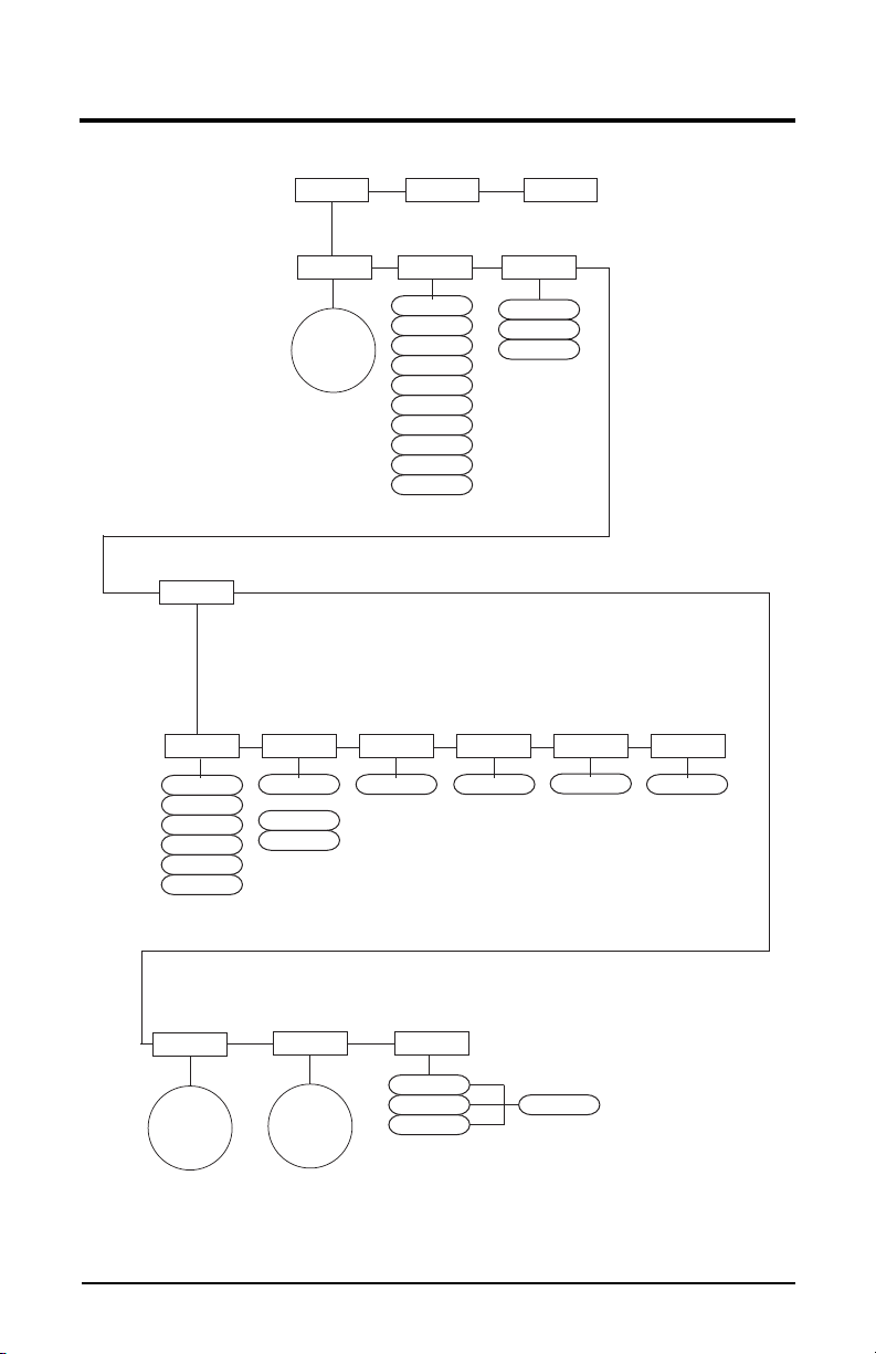
2.0 Configuration
CALIB FILTER PARA 0
SERIAL
0 SET
AUTO 0
TRAC 0
TESTOut-In
2
3
4
5
1
0
8
9
7
6
See
Serial
Submenu
See
Calib
Submenu
See
Serial
Submenu
IN
OUT
NU CEL
Enter #
ANALOG
MODE
TYPE
Enter #
0-10 V
0-20 mA
4-20mA
ANA 0 ANA FS COR FSCOR 0
Enter #
Enter #
Enter #Enter #
-5+5 V
-10+10 V
0-5 V
Gross
Net
000000
PtArE
SEtP1
Figure 2-1. Scale Menu Structure
Configuration 9
Page 14

Parameter Choices Description
CALIb FS-tEO
See Section 2.1“Calibration” on page 11.
SEnS I b
dI UI S
NASS
ZErO
1 NP 0
WEIGHt
unIt
COEFF
FILTER 0-9
4 *
PArA 0 0 SEt
AuTO 0
trAC 0
ANALOG tYPE
NOdE
ANA 0
ANA FS
COr 0
COr FS
SErIAL rS-485
bAud
Addr
dELAY
PArItY
STOP
Out-In Out 1
Out 2
In 1
In 2
tESt In
Out
ANALOG
NU-CEL
*
- indicates default value.
Allows a stable weight display to be obtained.
See Section 2.2 “Filter On The Weight” on page 19.
See Section 2.3 “Zero Parameters” on page 20.
See Section 2.4 “Analog Output” on page 21.
See Section 2.5 “Serial Communication Settings”
on page 23.
See Section 2.6 “Outputs And Inputs
Configuration” on page 26.
See Section 2.7 “Test” on page 28.
Table 2-1. Scale Menu
10 SCT Weight Transmitter Operator’s Manual
Page 15

2.1 Calibration
dI UI S
WEIGHt
unIt
COEFF
LItrE
bAr
AtN
PI ECE
nEUton
lb
OtHEr
HI LOG
HI LO-N
nEU-N
G
t
FS-tEO
Enter #
SEnS Lb
Enter #
NASS
Enter #
ZErO
Enter #
Enter # Enter #
I NP 0
Enter #
50
100
0.0001
0.0002
20
10
0.002
0.005
0.001
0.0005
2
5
0.02
0.05
0.01
0.2
0.5
0.1
1
FILtEr
PArA 0 SErIAL
tESt
Out-In
ANA LOG
000000
SEtP1
CALIb
PtArE
Note
Figure 2-2. Calibration Menu Structure
Parameter Choices Description
FS-TED Enter #
deno *
System Full Scale is determined by multiplying one
load cell capacity by the number of load cells used.
Example of system full scale value calculation:
4 cells of 1000kg ---->
FULL SCALE = 1000 X 4 = 4000
The instrument is supplied with a
theoretical full scale value deno
SENS LB Enter #
0.50000
to
7.00000
2.00000 *
Sensitivity is a load cell rated parameter expressed
in mV/V. Set the average sensitivity value indicated on
the load cells. I
Example of 4-cell system with sensitivity
2.00100, 2.00150, 2.00200, 2.00250;
calculated as (2.00100 + 2.00150 + 2.00200 +
Table 2-2. Calibration Menu
corresponding to 10000. To restore
factory values, set 0 as full scale.
enter 2.00175,
2.00250) / 4.
Configuration 11
Page 16

Parameter Choices Description
TARE
dI UI S 1
2 *
5
10
Division (resolution) - the weight increment (display
division size) that the scale counts by.
Selections are: 0.0001 and 100 with x1 x2 x5 x10
increments.
20
50
100
0.0001
0.0002
0.0005
0.001
0.002
0.005
0.01
0.02
0.05
0.1
0.2
0.5
NASS Enter #
0 *
to
max full scale
Maximum capacity (Live Load/Product) that can
be displayed. When the weight exceeds this value by
9 divisions, the display will go to dashes, indicating
overload.
Setting this value to 0 will disable the over capacity
function.
ZErO
0
Used to capture the deadload of the scale
system. With the scale empty, the displayed value
can be zeroed off. This menu may also be accessed
directly from the weighing mode to compensate for
zero changes or variations.
Press to display the accumulated weight that
has been zeroed off.
INP 0 Enter #
0 to 999999
0 *
Estimated dead load value of the scale when a
scale contains product that cannot be removed. The
value entered is the dead load. This value will be
replaced if the zero function is performed later.
Table 2-2. Calibration Menu
12 SCT Weight Transmitter Operator’s Manual
Page 17
Parameter Choices Description
Note
Note
WEIGHT Enter #
0 *
UNIT G
COEFF Enter #
*
- indicates default value.
t
Lb *
nEUton
LI trE
bAr
AtN
PI ECE
nEU-N
HI LO-N
OtHEr
HI LOG
0-99.9999
0 *
Weight (Span) Calibration - after the Theoretical
Calibration has been completed and zero is set, the
calibration can be adjusted with actual test weights
by changing the displayed value in this parameter.
If changes are made to the theoretical
Full Scale (
SEnSIb
(
parameters, the weight (span) calibration is
cancelled and the theoretical calibration is
initiated and applied.
If the theoretical full scale (
capacity full scale (
(span) calibration (
currently in use is theoretical; if they are different,
the calibration in use is the weight (span)
calibration based on calibration weights.
If changes are made to the theoretical full scale
(
FS-tEO
divisions (
parameters containing a weight value will be set
to default values (setpoints, hysteresis, etc.).
Unit of Measure - select to determine what unit of
measure is displayed and printed.
See Section 2.1.6 “Setting Units of Measure” on
page 17 for description of units.
Multiplier Value entered will display an alternative
unit of measure if the digital input is set for COEFF
and is in a closed state.
), the capacity full scale (
dI UI S
FS-tEO
) or Divisions (
FS-tEO
NASS
) are equal in weight
WEIGHt
), then the calibration
) parameters, all the system’s
), the Sensitivity
dI UI S
)
) and the
NASS
) or
Table 2-2. Calibration Menu
To calibrate the instrument, the “Theoretical Calibration” on
page 14 must be completed first. After Theoretical Calibration is
set, the scale can be set with actual weights (see Section 2.1.5
“Weight (Span) Calibration (With Test Weights)” on page 16).
Configuration 13
Page 18
2.1.1 Theoretical Calibration
Note
MENU
0
ESC
MENU
MENU
TARE
PRINT
MENU
TARE
PRINT
MENU
TARE
PRINT
MENU
TARE
PRINT
MENU
TARE
PRINT
MENU
0
ESC
Note
MENU
0
ESC
This function allows load cell rated values to be set.
To perform the theoretical calibration set FS-tED, SEnS lb and dI UI S in
sequence:
When entering a menu, the LED’s will begin scrolling, when
selection is made and confirmed the LED’s will be off.
1. Press and hold , then press , CALIb will be displayed.
2. Press , FS-tEO is displayed. Press .
3. Press or
until total load cell capacity (system full scale) is
displayed, press .
4. Press or
5. Press or
until SEnS lb is displayed, press .
until desired load cell mV/V is displayed,
press .
6. Press or
7. Press or
until dI UI S is displayed, press .
until desired display division size is displayed,
press .
8. This complete the Theoretical Calibration, press twice to exit setup menu or continue to Section 2.1.2.
By modifying the theoretical full scale, the sensitivity or divisions,
the weight (span) calibration is cancelled and the theoretical
calibration only is considered valid.
If the theoretical full scale and the recalculated full scale in weight
(span) calibration (see Section 2.1.5) are equal, this means that the
calibration currently in use is theoretical; if they are different, the
calibration in use is the weight (span) calibration based on test
weights.
By modifying the theoretical full scale, the sensitivity or divisions
and all the system’s parameters containing a weight value will be
set to default values (setpoints, hysteresis, etc.).
2.1.2 Maximum Capacity (NASS )
Maximum capacity (live load/product) that can be displayed. When the weight
exceeds this value by 9 divisions the following is displayed ‘
overload. To disable this function, set to 0.
------
’, indicating
1. Press and hold , then press . CALIb will be displayed.
14 SCT Weight Transmitter Operator’s Manual
Page 19

2. Press , FS-tEO is displayed.
MENU
TARE
PRINT
MENU
TARE
PRINT
MENU
0
ESC
Note
0
ESC
MENU
0
ESC
MENU
TARE
PRINT
MENU
MENU
0
ESC
Note
TARE
Important
MENU
0
ESC
MENU
TARE
PRINT
MENU
TARE
PRINT
MENU
0
ESC
3. Press or until NASS is displayed, press . LED’s will
begin scrolling.
4. Press or until desired capacity is displayed, press .
5. Press twice to exit set-up menu.
2.1.3 Zero Setting
Perform this procedure after having set the “Theoretical Calibration” on page 14.
This menu may also be accessed directly from the weight display,
press and hold for 3 seconds.
1. Press and hold , then press . CALIb will be displayed.
2. Press , FS-tEO is displayed.
3. Press or until ZErO is displayed, press .
4. The weight value to be set to zero is displayed. In this phase all of the
LEDs are flashing. Press , the weight is set to zero (the value is
stored to the permanent memory).
5. Press twice to exit set-up menu.
Press to display the accumulated deadload that has been
zeroed off by the instrument, displaying the sum of all of the
previous zero settings.
2.1.4 Zero Value Manual Entry
Perform this procedure only if it is not possible to reset the
weighed structure tare, for example because it contains
product that can not be unloaded.
Set in this parameter the estimated zero value.
1. Press and hold , then press . CALIb will be displayed.
2. Press , FS-tEO is displayed.
3. Press or until INP 0 is displayed, press . LED’s will
begin scrolling.
4. Press or until desired dead load is displayed, press .
5. Press twice to exit set-up menu.
Configuration 15
Page 20

2.1.5 Weight (Span) Calibration (With Test Weights)
MENU
0
ESC
MENU
TARE
PRINT
MENU
TARE
PRINT
MENU
MENU
0
ESC
Important
Note
After performing Section 2.1.1 “Theoretical Calibration” on page 14 and Section
2.1.3 “Zero Setting” on page 15, this function allows correct calibration to be
done using test weights of known value, if necessary, any deviations of the
indicated value from the correct value to be corrected.
1. Load the test weight onto the scale, use as high a percentage of the
maximum quantity to be weighed as possible.
2. Press and hold , then press . CALIb will be displayed.
3. Press , FS-tEO is displayed.
4. Press or
until UEIGHt is displayed, press .
5. The value of the weight currently on the system will be flashing on the
display. All of the LEDs are off. (If adjustment is not required, skip to
step 8.)
6. Adjust the value on display to match weight loaded on the scale if
necessary, by pressing or . The LED’s will begin scrolling.
7. Press , the new set weight will appear with all the LEDs flashing.
8. Press again, UEIGHt will be displayed.
9. Press twice to exit set-up menu.
Example:
For a system of maximum capacity of 1000 kg and 1 kg division, two test
weights are available, one 500 kg and one 300 kg. Load both weights onto the
system and correct the indicated weight to 800. Now remove the 300 kg
weight, the system must show 500; remove the 500 kg weight, too; the system
must read zero. If this does not happen, it means that there is a mechanical
problem affecting the system linearity.
Identify and correct any mechanical problems before
repeating the procedure.
If theoretical full scale and recalculated full scale in weight (span)
calibration are equal, it means that the theoretical calibration is
currently in use; otherwise, the weight (span) calibration based on
test weights is in use.
If the correction made changes the previous full scale for more
than 20%, all the parameters with settable weight values are reset
to default values.
Linearization Option On Max 5 Points:
It is possible to perform a linearization of the weight repeating the abovedescribed procedure up to a maximum of five points, using five different test
weights.
16 SCT Weight Transmitter Operator’s Manual
Page 21

The procedure ends by pressing or after entering the fifth value; at this
0
ESC
PRINT
MENU
0
ESC
MENU
TARE
PRINT
MENU
TARE
PRINT
MENU
0
ESC
Note
MENU
0
ESC
MENU
TARE
PRINT
MENU
point it will no longer be possible to change the calibration value, but only to
perform a new weight (span) calibration. To perform a new calibration, should
return to the weight display and then re-entering into the calibration menu.
By pressing after having confirmed the test weight that has been set, the full
scale appears, recalculated according to the value of the maximum test weight
entered and making reference to the cell sensitivity set in the theoretical
calibration (SEnSI b).
2.1.6 Setting Units of Measure
1. Press and hold , then press . CALIb will be displayed.
2. Press , FS-tEO is displayed.
3. Press or
until unIt is displayed, press .
4. Press or until desired unit is displayed, press .
5. Press twice to exit set-up menu.
HI LOG kilograms bAr bar*
G grams AtN atmospheres*
t tons PI ECE pieces*
Lb pounds* nEU-N newton metres*
nEUton newton* HI LO-N kikgram metres*
LI tre litres* OtHEr
other generic units of measure
not included in list*
* Indicates it is possible to set the display coefficient. To use COEFF it is
necessary to enable it, closing the COEFF input. See Section 2.1.7 “Display
Coefficient” on page 17.
If the print function is enabled, the symbol of the selected unit of
measure will be printed after the measured value.
2.1.7 Display Coefficient
By setting the coefficient the display is changed accordingly.
If one of the inputs is set to COEFF mode (see Section 2.6 “Outputs And Inputs
Configuration” on page 26) when the input is closed the value will be displayed
modified according to the coefficient; when the input is opened the standard
weight display will be restored.
1. Press and hold , then press . CALIb will be displayed.
2. Press , FS-tEO is displayed.
3. Press or
until COEFF is displayed, press . LED’s will
begin scrolling.
Configuration 17
Page 22

4. Press or until desired number is displayed, press .
TARE
PRINT
MENU
0
ESC
Important
5. Press twice to exit set-up menu.
HI LOG kilograms
G grams
t tons
Lb
nEUton
LI tre
bAr
AtN
pounds Value set in COEFF will be multiplied by the weight value
currently displayed
newton Value set in COEFF will be multiplied by the weight value
currently displayed
litres in COEFF set the specific weight in kg/l, assuming that
the system is calibrated in kg
bar Value set in COEFF will be multiplied by the weight value
currently displayed
atmospheres Value set in COEFF will be multiplied by the weight value
currently displayed
PI ECE pieces in COEFF set the weight of one piece
nEU-N
HI LO-N
OtHEr
newton metres Value set in COEFF will be multiplied by the weight value
currently displayed
kikgram metres Value set in COEFF will be multiplied by the weight value
currently displayed
other generic units
of measure not
Value set in COEFF will be multiplied by the weight value
currently displayed
included in list
Table 2-3. Coefficient Value by Unit of Measure
All other settings (setpoints, hysteresis, calibration ...) are
expressed in weight value. If you want to convert them to the
new unit of measurement, perform one of the following
procedures for changing the system calibration.
The parameter must remain set to 1.0000.
Theoretical Calibration For Other Units Of Measure
Set in the parameter the F.SCALE value divided by the conversion coefficient
from kg to the new unit of measure.
Example: The 4 load cells of 1000 kg are placed under a scale for oil, which
has a specific gravity of 0.916 kg / l. Setting the F.SCALE = (4x1000) / 0916 =
4367, the system works in liters of oil. If you set the unit to liters, the system
will display and print the symbol ‘l’ instead of ‘kg’. See Section 2.1.6 “Setting
Units of Measure” on page 17.
Weight (Span) Calibration For Other Units Of Measure
Load a known quantity of product liters on the scale (equal to at least 50% of the
maximum amount that you must weigh) and enter in the parameter UEI GHt, the
product loaded value in liters. If you set the units to liters, the system will
display and print the symbol ‘l’ instead of ‘kg’. See Section 2.1.6 “Setting Units
of Measure” on page 17.
18 SCT Weight Transmitter Operator’s Manual
Page 23

2.2 Filter On The Weight
MENU
0
ESC
TARE
PRINT
MENU
TARE
PRINT
MENU
MENU
MENU
0
ESC
Note
The filtering selection is used to eliminate environment noise, and is typically a
compromise between responsiveness and stability. The lower the number, the
more responsive the display will be to weight changes. The filter is used to
stabilize a weight as long as the variations are smaller than the corresponding
“Response Time”. The filter setting is dependent on the type of application and
the required update rate.
Setting this parameter allows a stable weight display to be obtained. To increase
the effect (weight more stable), increase the value.
1. Press and hold , then press . CALIb will be displayed.
2. Press or until FILtEr is displayed, press . LED’s will
begin scrolling.
3. Press or until desired filter value is displayed, press
4. The weight is displayed (all LED’s will be flashing) and the displayed
stability can be experimentally verified. Press .
5. If stability is not satisfactory, press , this returns indicator to FILtEr
option and the filter may be modified again until an optimum result is
achieved.
6. Press to exit set-up menu.
The filter enables to stabilize a weight as long as its variations are
smaller than the corresponding “Response Time”. It is necessary
to set this filter according to the type of application and to the full
scale value set.
Filter Value
Response times
[ms]
Display and serial port refresh frequency
[Hz]
080 80
1190 80
2260 40
3450 26
4* 900 13
5 1700 13
6 2500 13
7 4200 10
8 6000 10
9 7500 5
* indicates default value.
Table 2-4. Filter Settings
.
Configuration 19
Page 24

2.3 Zero Parameters
MENU
0
ESC
TARE
PRINT
MENU
TARE
PRINT
MENU
TARE
PRINT
MENU
0
ESC
1. Press and hold , then press . CALIb will be displayed.
2. Press or until PArA 0 is displayed, press .
3. Press or until desired parameter (see Table 5 ) is displayed,
press . The currently programmed value is displayed and LED’s
will be scrolling.
4. Press or until desired value is displayed, press .
5. Press twice to exit set-up menu.
Parameter Choices Description
0 SEt Enter #
0-max full scale
300 *
Considered decimals: 300
– 30.0 – 3.00 – 0.300
AutO 0 Enter #
0 - max 20% of full scale
0 *
trAC 0 nOnE *
1-5
*
- indicates default value.
Table 2-5. Zero Parameters Settings
Resettable Weight setting for small
weight change.
Indicates the maximum weight value
resettable by external contact, keypad or
serial protocol
Automatic zero setting at power-on
If when indicator is powered on the
weight value is lower than the value set
in this parameter and does not exceed
the 0 SEt value, the weight is reset.
To disable this function set to 0.
Zero tracking
When the zero weight value is stable
and, after a second, it deviates from zero
by a figure in divisions smaller or equal to
the figure in divisions set in this
parameter, the weight is set to zero.
To disable this function, set to none
Example: if the parameter dI UI
set to 5 and trAC 0 is set to 2, the
weight will be automatically set to
zero for variations smaller than or
equal to 10 (dI UI S x trAC 0 ).
S
is
20 SCT Weight Transmitter Operator’s Manual
Page 25

2.4 Analog Output
Note
Parameter Choices Description
tYPE 4-20 mA *
0-20 mA
0-10 V
0-5 V
-10 +10 V
-5 +5 V
NodE Enter #
Gross
Net
ANA 0 Enter # Set the weight value for the minimum analog output
ANA FS Enter # Set the weight value for the maximum analog output
COr 0 Analog output correction to zero: if necessary adjust
COr FS Full scale analog output correction: if necessary
*
- indicates default value.
Selects the analog output type.
See “Soldered Jumper” on page 22
See “Soldered Jumper” on page 22
Select mode to be tracked, gross or net. If the net
function is not active, the analog output varies
according to gross weight.
value.
Only set a value different from zero to
limit the analog output range.
E.G.:: for a full scale value of 10000 kg, a 4 mA
signal at 5000 kg is required, and 20 mA at 10000
kg, in this case, instead of zero, set 5000 kg.
value; it must correspond to the value set in the PLC
program (default: calibration full scale).
E.g.: if using a 4-20 mA output and in the PLC
program a 20 mA = 8000 kg is desired, set the
parameter to 8000.
the analog output, allowing the PLC to indicate 0.
The sign ‘-‘ can be set for the last digit on the left.
E.g.: For a 4-20 mA output and a minimum
analog setting, the PLC or tester reads 4.1 mA.
Set the parameter to 3.9 to obtain 4.0 on the PLC
or tester. (See “Analog Output Type Scale
Corrections” on page 22)
adjust the analog output, allowing the PLC to
indicate the value set in the AnA FS parameter.
E.g. For a 4-20 mA output with the analog set to
full scale and the PLC or tester reads 19.9 mA,
set the parameter to 20.1 to obtain 20.0 on the
PLC or tester. (See “Analog Output Type Scale
Corrections” on page 22)
Table 2-6. Analog Output Menu
Configuration 21
Page 26

Soldered Jumper
Note
For the output -10 +10 V and -5 +5 V the soldered jumper J7 must be closed:
• Remove the face plate of the instrument by removing the screws that attach
it to the little columns on the printed circuit board.
• On the circuit board, locate the jumper J7, situated above the 3 and 4
terminals at about mid board.
• Scrape away the solder from the jumper bay, until the copper underneath is
uncovered.
• Close the jumper short circuiting the bays, it is also recommended that a
small piece of copper wire without insulation or a leg wire be used to
facilitate the operation.
Analog Output Type Scale Corrections
Minimum and maximum values which can be set for the zero and full
scale corrections
Analog Output Type Minimum Maximum
0–10 V -0.150 10.200
0–5 V -0.150 5.500
-10 +10 V -10.300 10.200
-5 +5 V -5.500 5.500
0-20 mA -0.200 22.000
4-20 mA -0.200 22.000
The analog output may also be used in the opposite manner, i.e.
the weight setting that corresponds to the analog zero may be
greater than the weight set for the analog full scale. The analog
output will increase towards full scale as the weight decreases; the
analog output will decrease as the weight increases.
E.g.: analog output type having selected 0-10V
ANA 0 = 10000 ANA FS = 0
Weight = 0 kg analog output = 10 V
Weight = 5000 kg analog output = 5 V
Weight = 10000 kg analog output = 0 V
22 SCT Weight Transmitter Operator’s Manual
Page 27

2.5 Serial Communication Settings
Addr
bAud
HErt2
dELAY
PArItY
StOPrS485
nOnE
NodbUS
ASCII
Cont In
rI P
HdrI P
HdrI Pn
Enter #
9600
19200
38400
115200
4800
2400
30
40
50
60
20
10
80
70
Enter #
EUEn
Odd
nOnE
2
3
4
5
1
0
8
9
7
6
CALIb
FILtEr
PArA 0
SErIAL
tESt
Out-In
ANA LOG
Figure 2-3. Serial Communications Menu Structure
According to the chosen protocol only the necessary settings will be displayed
in sequence.
Parameter Choices Description
rS-485
(Communitcation
Port)
None * Disables any type of communication (default).
NOdbuS MODBUS-RTU protocol; possible addresses: from
1 to 99 (see Section 3.6)
ASCII ASCII bidirectional protocol; possible addresses:
from 1 to 99 (see Section 3.7)
NOdU6-
NOd td
COntIn Continuous weight transmission protocol (see
Section 3.8), at the frequency set in HERTZ
parameter (from 10 to 300).
NOd t(set: PARITY=none, STOP=1)
NOd td(set: PARITY=none, STOP=1)
rI P Continuous weight transmission protocol, streams
net and gross (see Section 3.9)
(set: BAUD=9600,PARITY=none, STOP=1)
Hdr1 P Continuous weight transmission protocol, streams
net and gross including decimal (see Section 3.9)
(set: BAUD=9600,PARITY=none, STOP=1)
Table 2-7. Serial Communications Menu
Configuration 23
Page 28

Parameter Choices Description
rS-485 (cont) Hdr1 PN Continuous weight transmission protocol (see
Section 3.9)
When the remote display is set to gross weight:
- if the instrument displays the gross weight, the
remote display shows the gross weight.
- if the instrument shows the net weight the remote
display shows the net weight alternated with the
message “net”
bAud 2400
4800
9600 *
19200
38400
115200
Addr 1-99
1 *
HErTZ Maximum Transmission Frequency - to be set
10Hz *
20Hz Max setting with min 2400 baud rate
30Hz
40Hz Max setting with min 4800 baud rate
50Hz
60Hz
70Hz
80Hz Max setting with min 9600 baud rate
dELAY 0-200
msec
0 *
PArItY nOnE *
EVEn
odd
StOP 1 *
2
*
- indicates default value.
Transmission speed.
Instruments address
when the CONTIN transmission protocol is
selected. (see Table 2-4 on page 19)
Delay in milliseconds which elapses before the
instrument replies
parity none
even parity
odd parity
Stop bit
Table 2-7. Serial Communications Menu
24 SCT Weight Transmitter Operator’s Manual
Page 29

2.5.1 RS-485 Serial Communication
SCTSCT
SCT
RS485 +
RS485 -
max 500 m
RS485 +
RS485 -
PC RS232
RX+
RX-
TX-
TX+
Converter
24 Vcc
+
-
0
TX
RX
VIN
RS485 +
RS485 -
RS485 termination
34
0 VDC
RS485 +
RS485 -
0 VDC
RS485 +
RS485 -
0 VDC
5 2 3
28 29
34
28 29 34
28 29
J2 J1
Figure 2-4. RS-485 Serial Communications
Configuration 25
Page 30

If the RS-485 network exceeds 100 metres in length or baud-rate
Note
Note
OUt 1
OUt 2 In 1 IN 2
CLOSE
OPEn
SEt 1
PLC
GrOSS
NEt
2ErO
PEAH
COntI n
PLC
nE-lO
COEFF
2Er0
PEAH
COntI n
PLC
nE-lO
COEFF
CLOSE
OPEn
SEt 2
StAbLE
POS/nEG
POS
nEG
OFF
On
CALIb
FILtEr
PArA 0 SErIAL
tESt
Out-In
ANA LOG
StAbLE
PLC
over 9600 are used, close the two jumpers, called "RS-485
termination", to activate two 120 ohm terminating resistors
between the ‘+’ and ‘–’ terminals of the line, on the terminal strip of
the furthest instrument. Should there be different instruments or
converters, refer to the specific manuals to determine whether it is
necessary to connect the above-mentioned resistors.
Direct Connection Between RS-485 And RS-232 Without Converter
Since a two-wire RS-485 output may be used directly on the RS-232 input of a
PC or remote display, it is possible to implement instrument connection to an RS232 port in the following manner:
Instrument RS-232
RS-485 - RXD
RS-485 + GND
This type of connection allows a SINGLE instrument to be used in a
ONE WAY mode.
2.6 Outputs And Inputs Configuration
Figure 2-5. Outputs and Inputs Menu Structure
26 SCT Weight Transmitter Operator’s Manual
Page 31

Parameter Choices Description
OUt 1
OUt 2
OUt 1
OUt 2
SEt 1
SEt 2
SEt 1
SEt 2
OPEn Normally Open: the relay is de-energized and the
contact is open when the weight is lower than the
programmed setpoint value; it closes when the weight
is higher than or equal to the programmed setpoint
value.
CLOSE * Normally closed: the relay is energized and the
contact is closed when the weight is lower than the
programmed setpoint value; it opens when the weight
is higher than or equal to the programmed setpoint
value.
SEt 1
SEt 2
PLC The contact will not switch on the basis of weight, but is
StAbLE Relay switching occurs when the weight is stable.
POSnEG * Relay switching occurs for both positive and negative
POS Relay switching occurs for positive weight values only.
NEG Relay switching occurs for negative weight values only.
OFF * Relay switching will not occur if the setpoint value is ‘0’.
On Setpoint = ’0’ and nodbus=posneg, relay switching
Number corresponds with OUT 1or 2.
The contact will switch on the basis of weight,
according to setpoints (see Section 2.8 “Setpoints
Programming” on page 29)
Select:
Gross (default) - the contact will switch on the basis
of gross weight.
or
Net - the contact will switch on the basis of net
weight (If the net function is not active, the
contact will switch on the basis of gross weight).
controlled by remote protocol commands.
weight values.
occurs when the weight is ‘0’; the relay will switch
again when the weight is different from zero, taking
hysteresis into account (both for positive and for
negative weights).
Setpoint = ’0’ and nodes=pos, relay switching occurs
for a weight higher than or equal to ‘0’, the relay will
switch again for values below ‘0’, taking hysteresis
into account.
Setpoint = ’0’ and nodes=neg, relay switching occurs
for a weight lower than or equal to ‘0’, the relay will
switch again for values above ‘0’, taking hysteresis
into account.
Table 2-8. Output and Input Menu
Configuration 27
Page 32

Parameter Choices Description
MENU
0
ESC
TARE
PRINT
MENU
TARE
PRINT
MENU
MENU
TARE
PRINT
MENU
0
ESC
In 1
In 2
*
- indicates default value.
nE-LO *
(In 2
default)
(NET/GROSS): by closing this input for less than one
second, it performs a SEMI-AUTOMATIC TARE and the
display will show the net weight. To display the gross
weight again, hold the NET/GROSS input closed for 3
seconds.
2ErO *
(In 1
default)
By closing the input for less than one second, the
weight is set to zero (see Section 3.3 “Semi-Automatic
Zero (Weight Zero-setting For Small Variations)” on
page 33).
PEAH With the input closed the maximum weight value
reached remains on display. Opening the input the
current weight is displayed.
PLC Closing the input no operation is performed, the input
status may however be read remotely by way of the
communication protocol.
COntin Closing the input for less than one second the weight is
transmitted via the serial connection according to the
fast continuous transmission protocol one time only
(only if contin is set in the item serial).
COEFF When the input is closed the weight is displayed based
on the set coefficient (see Section 2.1.6 “Setting Units
of Measure” on page 30 and Section 2.1.7 “Display
Coefficient” on page 31), otherwise the weight is
displayed.
Table 2-8. Output and Input Menu
2.7 Test
1. Press and hold , then press . CALIb will be displayed.
2. Press or until tEst is displayed, press . The currently
programmed value is displayed.
3. Press or until desired parameter is displayed, press .
4. For In and NU-CEL, current reading is displayed, press .
For Out, press until corresponding value of the out you want to
change is flashing, press to change the value, press .
5. Press twice to exit set-up menu.
28 SCT Weight Transmitter Operator’s Manual
Page 33

Parameter Choices Description
MENU
TARE
PRINT
MENU
TARE
PRINT
MENU
0
ESC
Note
In N/A Input Test - for each open input 0 is displayed, 1 is
displayed when the input is closed.
Out 0 *
1
Output Test Setting 0 - the corresponding output opens.
Setting 1 - the corresponding output closes.
ANALOG ANALOG Allows the analog signal to range between the minimum
and the maximum values starting from the minimum.
NA current output test
UOLt1 voltage output test
NU-CEL N/A Millivolt Test - displays the load cell response signal in
mV with four decimals.
*
- indicates default value.
Table 2-9. Test Menu
2.8 Setpoints Programming
1. Press to enter setpoints and hysteresis settings.
2. Press or
until desired setpoint or hysteresis parameter is
displayed, press .
3. Press or until desired value is displayed, press .
4. Press to exit setpoints and hysteresis settings.
These values are set to zero if the calibration is changed
significantly (see Section 2.1.1 “Theoretical Calibration” on
page 14 and Section 2.1.5 “Weight (Span) Calibration (With Test
Weights)” on page 16).
Parameter Choices Description
SEtP 1
SEtP 2
HYStE 1
HYStE 2
*
- indicates default value.
0-Full Scale
0 *
0-Full Scale
0 *
Setpoint; relay switching occurs when the weight
exceed the value set in this parameter. The type of
switching is settable (see “Outputs And Inputs
Configuration” on page 26).
Hysteresis, value to be subtracted from the setpoint to
obtain contact switching for decreasing weight. For
example with a setpoint at 100 and hysteresis at 10,
the switching occurs at 90 for decreasing weight.
Table 2-10. Setpoints
Configuration 29
Page 34

2.9 Reserved For The Installer
Important
0
ESC
MENU
MENU
Note
0
ESC
MENU
TARE
MENU
0
ESC
Note
2.9.1 Default Scale
Operation must only be performed after contacting technical
assistance
1.With power off, press and hold , then power on.
Display shows PrOG .
2. Press , display shows bASE.
3. Press , display shows UAIt.
4. Instrument will reboot.
By confirming the displayed program, the system variables are set
with default values.
2.9.2 Program Selection - Reverse:
Scale capacity is displayed when scale is empty. As weight is added display will
count down.
1. With power off, press and hold , then power on.
Display shows PrOG .
2. Press , display shows bASE.
3. Press , display shows rEuEr.
4. Press , display shows UAIt.
5. Instrument will reboot.
By pressing you will quit the program without introducing any changes and
without deleting any of the set variables.
If you do not have a specific manual for the newly set program, you
can request it from technical assistance.
30 SCT Weight Transmitter Operator’s Manual
Page 35

2.9.3 Keypad Or Display Locking
0
ESC
PRINT
TARE
MENU
1. Press immediately followed by , hold them down for about 5
seconds (this operation is also possible via the MODBUS and ASCII
protocols):
2. Press or until desired parameter is displayed, press .
Parameter Description
FrEE no lock
KEY keypad lock: if active, when key is pressed the message bLOC is
displayed.
dI SP Keypad and Display lock: if active, the keypad is locked and the
display shows the instrument model (weight is not displayed); by
pressing a key the display shows bLOC for 3 seconds.
Configuration 31
Page 36

3.0 Operation
Note
TARE
TARE
Note
PRINT
PRINT
MENU
TARE
MENU
TARE
PRINT
MENU
0
ESC
Note
PRINT
PRINT
TARE
3.1 Semi-Automatic Tare (Net/Gross)
The semi-automatic tare value is lost upon instrument power-off.
The semi-automatic tare operation is not allowed if the gross
weight is zero.
1. To capture tare and weigh in net mode (SEMI-AUTOMATIC TARE),
close the NET/GROSS input or press for 3 seconds. The
instrument displays the net weight (zero) and the NET LED lights up.
2. To display the gross weight again, keep the NET/GROSS input closed
or press for 3 seconds.
3. This operation can be repeated by the operator to allow the loading of
several products.
Press and hold to display the gross weight temporarily. When
is released, the net weight will be displayed again.
3.2 Preset Tare (Subtractive Tare Device)
It is possible to manually set a preset tare value to be subtracted from the display
value provided that the P-tArE ≤ max capacity.
1. Press and hold and to display P-tArE, press .
2. Press or until desired value is displayed, press .
3. Press to exit P-tArE.
4. After setting the tare value, go back to the weight display, the display
shows the net weight (subtracting the preset tare value) and the NET
LED lights up to show that a tare has been entered.
Press and hold for 3 seconds to display the gross weight
temporarily. When is released, the net weight will be
displayed again.
To delete a preset tare and return to the gross weight display:
1. Press hold for 3 seconds or keep the NET/GROSS input (if any)
closed for the same length of time (3 seconds). The preset tare value is
set to zero. The NET LED is turned off when the gross weight is
displayed once again.
32 SCT Weight Transmitter Operator’s Manual
Page 37

If a semi-automatic tare (net) is entered, it is not possible to access
Note
Note
0
ESC
the enter preset tare function.
If a preset tare is entered, it is still possible to access the
semiautomatic tare (net) function. The two different types of tare
are added.
All the semi-automatic tare (net) and preset tare functions will be
lost when the instrument is turned off.
3.3 Semi-Automatic Zero (Weight Zero-setting For Small Variations)
By closing the SEMI-AUTOMATIC ZERO input, the weight is set to zero. The
zero setting will be lost when the instrument is turned off.
This function is only allowed if the weight is lower than the 0 set value (see 0
SET in Section 2.3 “Zero Parameters” on page 20), otherwise the t
-----
alarm
appears and the weight is not set to zero.
3.4 Peak
By keeping the input closed the maximum weight value reached remains
displayed. Opening the input the current weight is displayed.
If you wish to use this input to view a sudden variation peak, set
the FILTER ON THE WEIGHT (see Section 2.2) to 0.
3.5 Alarms
Display Description
ErCEL Load cell is not connected or is incorrectly connected; the load cell signal
Er OL Weight display exceeds 110% of the full scale.
Er Ad Internal instrument converter failure; check load cell connections, if
---------
Er OF Maximum displayable value exceeded (value higher than 999999 or lower
-------
t
NAH-PU This message appears in the test weight setting, in weight (span)
Err0r The value set for the parameter is beyond the permitted values; press
bLOC Lock active on menu item, keypad or display.
nOdl SP It’s not possible to display properly the number because is greater than
exceeds 39 mV; the conversion electronics (A/D converter) is
malfunctioning.
necessary contact Technical Assistance.
Weight exceeds the maximum weight by 9 divisions.
than -999999).
Weight too high: zero setting not possible.
calibration, after the fifth test weight value has been entered.
to quit the setting mode leaving the previous value unchanged.
Examples:
-a number of decimals is selected for full scale which exceeds the
instrument's display potential;
-value above the maximum setting value;
-the weight value set in test weight verification does not match the
detected mV increase.
999999 or less than -999999.
Table 3-1. Alarm Descriptions
Operation 33
Page 38

-----
Note
The response
to the zero
command is a
'value not
valid' error
(error code 3)
MODE
Bit LSB
Status
Register
MODBU
S RTU
ASCII
RIP *
HDRIP-N
CONTIN
ErCEL Er OL Er Ad --------- Er OF t
76543210
xxxxxxx1
__O-F_ __O-L_ __O-F_ __O-L_ __O-F_ &aa#CR
__O-F_ __O-L_ __O-F_ __O-L_ __O-F_ __O-F_
_ERCEL _ER_OL _ER_AD ###### _ER_OF O__SET
_ERCEL _ER_OL _ER_AD ^^^^^^ _ER_OF O__SET
76543210
xxxx1xxx
76543210
xxxxxx1x
76543210
xxxxx1xx
76543210
On gross:
xxx1xxxx
On net:
xx1xxxxx
Table 3-2. Serial Protocols Alarms
* For RIP remote displays, if the message exceeds 5 digits the display
------
reads
Range 0/20mA 4/20 mA 0/5 V 0/10 V -10/10 V -5/5 V
Output
Value
.
If an alarm becomes active the relays open and the analog outputs
go to the lowest possible value according to the following table:
-0.2 mA 3.5 mA -0.5 V -0.5 V 0 V 0 V
3.6 Modbus-RTU Protocol
The MODBUS-RTU protocol enables to manage the reading and writing of the
registers listed here below according to the specifications contained in the
reference document for this standard Modicon PI-MBUS-300.
To select the communication with MODBUS-RTU, refer to Section 2.4 “Analog
Output” on page 21.
When specifically indicated certain data will be written directly to EEPROM
type memories. This memory has a limited number of writing operations
(100.000), therefore unnecessary operations at said locations must be avoided.
The instrument, in any case, ensures that no writing occurs if the value to be
stored is equal to the stored value.
The numerical data listed below are expressed in decimal notation, or
hexadecimal notation if preceded by 0x.
Modbus-RTU Data Format
The data received and transmitted via MODBUS-RTU protocol have the
following characteristics:
- 1 start bit
- 8 data bits, least significant bit sent first
- Instrument settable parity bit
- Instrument settable stop bit
34 SCT Weight Transmitter Operator’s Manual
Page 39

Modbus Supported Functions
Among the commands available in the MODBUS-RTU protocol, only the
following are used to manage communication with the instruments. Other
commands may not be interpreted correctly and could generate errors or system
shut-downs:
FUNCTIONS DESCRIPTION
03 (0x03) Read Holding Register (Programmable Register Reading)
16 (0x10) Preset Multiple Registers (Write Multiple DI Register)
The interrogation frequency is linked with the preset communication rate (the
instrument will stand by for at least 3 bytes before beginning to calculate a
possible response to the query). The dELAY parameter (see Section 2.4 “Analog
Output” on page 21) allows for a further delay in the instrument response, and
this directly influences the number of possible queries in the unit of time.
For additional information on this protocol, refer to the general technical
specification PI_MBUS_300. The functions supported relative to the MODBUS
standard are the READ HOLDING REGISTER and the PRESET MULTIPLE
REGISTERS.
In general, the query and response to and from a slave instrument are organized
as follows:
Function 3: Read Holding Registers (Programmable Register Reading)
QUERY
Address Function Add. Reg. 1 No. register 2 bytes
A 0x03 0x0000 0x0002 CRC
Tot. bytes = 8
RESPONSE
Address Function No. bytes Register1 Register 2 2 bytes
A 0x03 0x04 0x0064 0x00C8 CRC
Tot. bytes = 3+2*No. registers+2
Function 16: Preset Multiple Registers (Multiple Register Writing)
QUERY
Address Function
A 0x10 0x0000 0x0002 0x04 0x0000 0x0000 CRC
Add.
reg. 1 No. reg.
No.
bytes
Val .
reg.1
Val .
reg.2 2 bytes
Tot. bytes = 7+2*No. registers+2
RESPONSE
Address Function Add. Reg. 1 No. register 2 bytes
A 0x10 0x0000 0x0002 CRC
Tot. bytes = 8
No. REGS: Number of registers to write beginning from the address.
Operation 35
Page 40

N° BYTES: Number of bytes transmitted as a value of the registers (2
bytes per register)
VAL. REG.: Contents of the register beginning from the first.
The answer contains the register identification modified after the command has
been executed.
Communication Error Management
The communication strings are controlled by CRC (Cyclical Redundancy
Check).
In case of a communication error the slave will not respond with any string. The
master must allow for a time-out before response reception. If no response is
received it infers that a communication error has occurred.
In the event of a string received correctly but not executable, the slave responds
with an EXCEPTIONAL RESPONSE. The "FUNCTION" field is transmitted
with the MSB at 1.
EXCEPTIONAL RESPONSE
Address Function Code 2 bytes
A Funct + 80h CRC
CODE DESCRIPTION
1 ILLEGAL FUNCTION (Function not valid or not supported)
2 ILLEGAL DATA ADDRESS (The specified data address is not available)
3 ILLEGAL DATA VALUE (The data received have no valid value)
List Of Usable Registers
The MODBUS-RTU protocol implemented on this instrument can manage a
maximum of 32 registers read and written in a single query or response.
R = the register can be read only
W = the register can be written only
R/W = the register can be both read and written
H = high half of the DOUBLE WORD forming the number
L = low half of the DOUBLE WORD forming the number
36 SCT Weight Transmitter Operator’s Manual
Page 41

REGISTER
Important
40001 Firmware version - R
40002 Type of instrument - R
40003 Year of Production - R
40004 Serial Number - R
40005 Active program - R
40006 Command Register NO W
40007 Status Register - R
40008 Gross Weight H - R
40009 Gross Weight L - R
40010 Net Weight H - R
40011 Net Weight L - R
40012 Peak Weight H - R
40013 Peak Weight L - R
40014 Divisions and Units of measure - R
40015 Coefficient H R
40016 Coefficient L R
40017 SETPOINT 1 H
40018 SETPOINT 1 L R/W
40019 SETPOINT 2 H R/W
40020 SETPOINT 2 L R/W
40021 HYSTERESIS 1 H R/W
40022 HYSTERESIS 1 L R/W
40023 HYSTERESIS 2 H
40024 HYSTERESIS 2 L
40025 INPUTS - R
40026 OUTPUTS NO R/W
40037 Test weight for calibration H Use with command
40038 Test weight for calibration L R/W
40043 Weight value corresponding to
ZERO of the analog output H
40044 Weight value corresponding to
ZERO of the analog output L
40045 Weight value corresponding to
Full Scale of the analog output H
40046 Weight value corresponding to
Full Scale of the analog output L
DESCRIPTION
At the time of writing, the setpoints, hysteresis values are
saved to the RAM and will be lost upon the next power-off; to
store them permanently to the EEPROM so that they are
maintained at power-on, the ‘99’ command of the Command
Register must be sent.
Saving to EEPROM ACCESS
Only after command
‘99’ of the COMMAND
REGISTER
‘101’ of the
COMMAND REGISTER
Only after command
‘99’ of the
Command Register.
R/W
R/W
R/W
R/W
R/W
R/W
Operation 37
Page 42

Weight (Span) Calibration Commands (With Test Weights)
The instrument calibration can be changed via MODBUS. To carry out this
procedure, the system must be unloaded and the weight value display reset to
zero with the command ‘100’ of the Command Register. Then, a load must be
placed on the system and the correct weight value must be sent to the registers
40037-40038; to save this value, send the control ‘101’ from the Command
Register. If the operation is successfully completed, the two test weight registers
are set to zero.
Analog Output Setting
Write the weight in the registers “Weight value corresponding to the Full Scale of
analog output H” (40045) and “Weight value corresponding to the Full Scale of
analog output L” (40046) or write the weight in the registers “weight value
corresponding to the ZERO of the analog output H” (40043) and “weight value
corresponding to the ZERO of the analog output L” (40044). After writing the
value, send the command 99 from the Command Register to save it to EEPROM
memory.
Status Register
Bit 0
Bit 1
Bit 2
Bit 3
Bit 4
Bit 5
Bit 6
Bit 7
Bit 8
Bit 9
Bit 10
Bit 11
Bit 12
Bit 13
Bit 14
Bit 15
Cell Error
AD Convertor Malfunction
Maximum weight exceeded by 9 divisions
Gross weight higher than 110% of full scale
Gross weight beyond 999999 or less than -999999
Net weight beyond 999999 or less than -999999
Gross weight negative sign
Net weight negative sign
Peak weight negative sign
Net display mode
Weight stability
Weight within +/-¼ of a division around ZERO
38 SCT Weight Transmitter Operator’s Manual
Page 43

Inputs Register (40025)
Note
(Read Only)
Bit 0 INPUT 1 Status Bit 0 OUTPUT 1 Status
Bit 1 INPUT 2 Status Bit 1 OUTPUT 2 Status
Bit 2 Bit 2
Bit 3 Bit 3
Bit 4 Bit 4
Bit 5 Bit 5
Bit 6 Bit 6
Bit 7 Bit 7
Bit 8 Bit 8
Bit 9 Bit 9
Bit 10 Bit 10
Bit 11 Bit 11
Bit 12 Bit 12
Bit 13 Bit 13
Bit 14 Bit 14
Bit 15 Bit 15
The output status can be read at any time but can be set (written)
only if the output has been set as or (see Section 2.6 “Outputs And
Inputs Configuration” on page 26); otherwise, the outputs will be
managed according to the current weight status with respect to
the relevant setpoints.
Divisions And Units Measure Registry (40014)
Outputs Register (40026)
(Read And Write)
This register contains the current setting of the divisions (parameter dI UI S ) and
of the units of measure (UnI t parameter).
H Byte L Byte
Units of measure division
Use this register together with the Coefficient registers to calculate the value
displayed by the instrument.
Operation 39
Page 44

Least significant byte
(L Byte)
Division
value
0 100 0 0 Kilograms Does not intervene
1 50 0 1 Grams Does not intervene
2 20 0 2 Tons Does not intervene
3 10 0 3 Pounds Does not intervene
4 5 0 4 Newton Multiples
520 5 Litres Divides
6 1 0 6 Bar Multiples
7 0.5 1 7 Atmspheres Multiples
8 0.2 1 8 Pieces Divides
90.11 9 Newton
10 0.05 2 10 Kilogram
11 0.02 2 11 Other Multiples
12 0.01 2
13 0.005 3
14 0.002 3
15 0.001 3
16 0.0005 4
17 0.0002 4
18 0.0001 4
Divisor Decimals
Units of
measure
value
Most significant byte
(H Byte)
Utilization of the
Coefficient value
Units of
measure
description
Meter
Meter
with the different
units of measure
settings compared
to the gross weight
Multiples
Multiples
detected
40 SCT Weight Transmitter Operator’s Manual
Page 45

Possible Command To Send To The Command Register (40006)
0
1
2
3
4
5
6
7
8
9
10
11
12
13
14
15
16
No command
NET display
SEMI-AUTOMATIC ZERO
GROSS display
Reserved
Reserved
Reserved
Reserved
Reserved
Reserved
Reserved
17
18
19
20
21
22
23
24
99
100
101
9999
Reserved
Reserved
Keypad lock
Keypad and display unlock
Keypad and display lock
Save data in EEPROM
Zero-setting for calibration
Test weight storage for calibration
Reset (reserved)
3.7 ASCII Bidirectional Protocol
The instrument replies to the requests sent from a PC/PLC.
It is possible to set a delay time for the instrument before it transmits a response
(see dELAY parameter in Section 2.4 “Analog Output” on page 21).
The following communication modes available (see Section 2.4 “Analog Output”
on page 21):
• NOdU60:
• NOd td:
Data Identifiers:
$: Beginning of a request string (36 ASCII);
& o &&: Beginning of a response string (38 ASCII);
aa: 2 characters for instrument address (48 ÷ 57 ASCII);
!: 1 character to indicate the correct reception(33 ASCII);
?: 1 character to indicate a reception error (63 ASCII);
#: 1 character to indicate an error in the command execution (23 ASCII);
ckck: 2 ASCII characters for Check-Sum (for furthers information, see
“Check-Sum Calculation” on page 45);
CR: 1 character for string end (13 ASCII);
\: 1 character for separation (92 ASCII).
Operation 41
Page 46

Setpoint Values Setting:
Note
The PC transmits: $aaxxxxxxyckckCR
in which:
xxxxxx = 6 characters for the setpoint value (48 ÷ 57 ASCII);
y = A (set the value in the Setpoint 1)
y = B (set the value in the Setpoint 2)
Possible instrument responses:
- correct reception: &&aa!
- incorrect reception: &&aa?
Setpoints Storage Into EEPROM Memory:
\ckckCR
\ckckCR
The setpoints value relevant to the two setpoints programmed via the PC are
stored to the RAM volatile memory and lost upon instrument power off. It is
necessary to send a special command to save them permanently in the EEPROM
memory. Please note that the number of writes allowed in the EEPROM memory
is limited (about 100000).
The PC transmits: $aaMEM
ckckCR
Possible instrument responses:
- correct reception: &&aa!
- incorrect reception: &&aa?
Reading Weight, The Setpoint And The Peak (If Present) From The Pc:
\ckckCR
\ckckCR
The PC transmits: $aajckckCR
in which:
j = a to read setpoint 1
j = b to read setpoint 2
j = t to read gross weight
j = n to read net weight
j = p to read the gross weight peak if the ASCII parameter is set as
NOdU60; if, instead the ASCII parameter is set on NOd td the
gross weight will be read. To read the points, set the FStE0
equal to 50000.
Possible instrument responses:
- correct reception: &aaxxxxxxj\ckckCR
- incorrect reception: &&aa?\ckckCR
- if the peak is not configured: &aa#
CR
in which:
xxxxxx = 6 value characters of the required weight.
In case of negative weight, the first character on the left acquires
the value « - » (minus sign - ASCII 45).
In case of weight value is under -99999, the minus sign (‘-‘) is sent
alternated with the most significant figure.
42 SCT Weight Transmitter Operator’s Manual
Page 47

Error messages:
Important
In case of an instrument alarm for exceeding 110% of the full scale or 9 divisions
above the value of the parameter NASS, the instrument sends the string:
&aassO-Lst
\ckck
In case of faulty connection of the load cells or of another alarm, the instrument
sends:
&aassO-Fst
\ckck
in which:
s = 1 separator character (32 ASCII – space-).
Refer to Section 3.5 “Alarms” on page 33.
Semi-Automatic Zero (Weight Zero-Setting For Small Variations)
The zero-setting will not be maintained after an instrument
power-off.
The PC transmits: $aaZEROckckCR
Possible instrument responses:
- correct reception: &&aa!
- incorrect reception: &&aa?
- the current weight is over the maximum value resettable: &aa#
Switching From Gross Weight To Net Weight
\ckckCR
\ckckCR
CR
The PC transmits: $aaNETckckCR
Possible instrument responses:
- correct reception: &&aa!\
- incorrect reception: &&aa?
Switching From Net Weight To Gross Weight
ckckCR
\ckckCR
The PC transmits: $aaGROSSckckCR
Possible instrument responses:
- correct reception: &&aa!
- incorrect reception: &&aa?
Reading Of Decimals And Number Of Divisions
\ckckCR
\ckckCR
The PC transmits: $aaDckckCR
Possible instrument responses:
- correct reception: &aaxy
- incorrect reception: &&aa?
\ckckCR
\ckckCR
in which:
x = number of decimals
y = division value
The y field acquires the following values:
'3' for division value = 1
'4' for division value = 2
'5' for division value = 5
'6' for division value = 10
'7' for division value = 20
Operation 43
Page 48

'8' for division value = 50
Important
'9' for division value = 100
Zero Setting
(See Section 2.1.3)
The PC transmit the following ASCII string containing the zeroing command:
$aaz
ckckCR
in which:
z = weight zeroing command (122 ASCII)
Possible instrument responses:
- correct reception: &aaxxxxxxt
- incorrect reception: &&aa?
\ckckCR
\ckckCR
- If the instrument is not in gross weight displaying condition, the
response is: &aa#
CR
in which:
xxxxxx = 6 characters for the required weight value;
t = weight identification code (116 ASCII).
Example: Weight zero setting for instrument with address 2:
For the calibration, make sure that the scale is empty and the instrument
measures a corresponding mV signal.
query: $02z78(Cr) response: &02000000t\76(Cr)
In case of correct weight zero setting the read value (response) must be 0 (in the
string “000000”).
The zero values are stored to the EEPROM memory, please
note that the number of writes allowed is limited (about
100000). If it is necessary to reset the weight quite often, it is
recommended to perform it by PC or PLC program, keeping
in mind the weight deviation respect to the zero instrument.
Weight (Span) Calibration (With Test Weights)
(See Section 2.1.5)
After having performed the ZERO SETTING (see Section 2.1.3 “Zero Setting”
on page 15), this function allows correct calibration to be done using test weights
of known value and, if necessary, any deviations of the indicated value from the
correct value to be corrected.
Load onto the weighing system a test weight, Load the test weight onto the scale,
use as high a percentage of the maximum quantity to be weighed as possible.
Otherwise make sure that the instrument measures a corresponding mV signal.
The PC sends the following ASCII string containing the calibration command:
$aasxxxxxx
ckckCR
in which:
s = calibration command (115 ASCII)
xxxxxx = 6 characters for test weight value.
Possible instrument responses:
- correct reception: &aaxxxxxxt
- incorrect reception or full scale equal to zero: &&aa?
\ckckCR
\ckckCR
44 SCT Weight Transmitter Operator’s Manual
Page 49

in which:
t = gross weight identification code (116 ASCII).
xxxxxx = 6 characters to indicate the current weight value.
In case of correct calibration, the read value must be equal to test weight.
Example: Calibration for instrument with address 1 and test weight of 20000 kg:
query: $01s02000070(Cr) response: &01020000t\77(Cr)
In case of correct calibration the read value has to be “020000”.
Keypad Lock (Access Protection To The Instrument)
The PC transmits: $aaKEYckckCR
Possible instrument responses:
- correct reception: &&aa!
- incorrect reception: &&aa?
Keypad Unlock
\ckckCR
\ckckCR
The PC transmits: $aaFREckckCR
Possible instrument responses:
- correct reception: &&aa!
- incorrect reception: &&aa?
Display And Keypad Lock
\ckckCR
\ckckCR
The PC transmits: $aaKDISckckCR
Possible instrument responses:
- correct reception: &&aa!
- incorrect reception: &&aa?
Check-Sum Calculation
\ckckCR
\ckckCR
The two ASCII control characters (ckck) are the representation of a hexadecimal
digit in ASCII characters. The check digit is calculated by performing the
operation XOR (exclusive or) 8-bit ASCII codes of the only part of the
underlined string.
The procedure to calculate the check- sum is the following:
• Consider only the string characters highlighted with underlining;
• Calculate the EXCLUSIVE OR (XOR) of the ASCII codes for the
characters;
Example:
Character
0 48 30 00110000
1 49 31 00110001
t 116 74 01110100
XOR = 117 75 01110101
Decimal ASCII
Code
Hexadecimal ASCII
Code
Binary ASCII
Code
• The result of the XOR operation expressed in hexadecimal notation is made
up of 2 hexadecimal digits (numbers from 0 to 9 or letters from A to F). In
this case the hexadecimal code is 0x75.
• The check-sum inserted in the strings transmitted is made up of the 2
characters which represent the result of the XOR operation in hexadecimal
notation (in our example the character " 7 " and the character " 5)
Operation 45
Page 50

3.8 Fast Continuous Transmission Protocol
This protocol allows for continuous serial output at high update frequencies. Up
to 80 strings per second are transmitted (with a minimum transmission rate of
9600 baud). See “Filter Settings” on page 19 for limitations.
Following communication modes available (see Section 2.4 “Analog Output” on
page 21):
• NOd t: communication compatible with TX RS-485 instruments;
• NOd td: communication compatible with TD RS-485 instruments.
•If NOd t is set, the following string is transmitted to PC/PLC: xxxxxxCRLF
in which:
xxxxxx = 6 ASCII characters for gross weight (48 ÷ 57 ASCII).
CR = 1 character of carriage return (13 ASCII).
LF = 1 character of line feed (10 ASCII).
In case of negative weight, the first character on the left acquires the value
« - » (minus sign - ASCII 45).
In case of error or alarm, the 6 weight characters are replaced by the
messages found in “Alarm Descriptions” on page 33.
•If NOd td is set, the following string is transmitted to PC/PLC:
&TzzzzzzPzzzzzz\ckckCR
in which:
& = 1 character of string start (38 ASCII).
T = reference character for gross weight.
P = reference character for gross weight.
zzzzzz = 6 ASCII characters for gross weight (48 ÷ 57 ASCII).
\ = 1 character of separation (92 ASCII).
ckck = 2 ASCII control characters calculated considering that the
characters between & and \ are excluded. The control value is obtained by
carrying out the XOR (or exclusive) operation for the 8 bit ASCII codes of
the characters considered. A character expressed in hexadecimal is thus
obtained, with 2 digits which may acquire values from “0” to “9” and from
“A” to “F”. “ckck” is the ASCII code of the two hexadecimal digits.
CR = 1 character for string end (13 ASCII).
In case of negative weight, the first character on the left acquires the value
« - » (minus sign - ASCII 45).
In case of error or alarm, the 6 gross weight characters are replaced
by the messages found in “Alarm Descriptions” on page 33.
Fast Transmission Via External Contact: A single string can be transmitted by
closing a digital input, not exceeding 1 second. (see Section 2.6 “Outputs And
Inputs Configuration” on page 26 and Section 2.4 “Analog Output” on page 21).
3.9 Continuous Transmission Protocol To Remote Displays
Using this protocol, the instrument transmits, in continuous mode, the weight to
remote displays; the communication string is transmitted 10 times per second.
Following communication modes are available (see Section 2.4 “Analog Output”
on page 21):
• rl P: remote display shows the net or gross weight, depending on the remote
display setting.
46 SCT Weight Transmitter Operator’s Manual
Page 51

• Hdrl P: remote display shows the net or gross weight, depending on the
Note
remote display setting.
• Hdrl Pn:
See next page for more information.
The instrument sends the following string to the remote display:
&NxxxxxxLyyyyyy
\ckckCR
in which:
& = 1 character of string start (38 ASCII).
N = 1 reference character for net weight. (78 ASCII).
xxxxxx = 6 ASCII characters for net or peak weight if present (48 ÷ 57
ASCII).
L = 1 reference character for gross weight (76 ASCII).
yyyyyy = 6 ASCII characters for gross weight (48 ÷ 57 ASCII).
\ = 1 character for separation (92 ASCII).
ckck = 2 ASCII control characters calculated considering that the
characters between “&” and “\” are excluded. The control value is
obtained by carrying out the XOR (or exclusive) operation for the 8 bit
ASCII codes of the characters considered. Character expressed in
hexadecimal is thus obtained, with 2 digits which may acquire values from
“0” to “9” and from “A” to “F”. “ckck” is the ASCII code of the two
hexadecimal digits.
CR = 1 character for string end (13 ASCII).
In case of negative weight, the first character on the left acquires the value « - »
(minus sign - ASCII 45).
If the protocol on Hdrl P has been set, the decimal point at the position shown on
the instrument's display can also be transmitted. In this case, if the value exceeds
5 digits, only the 5 most significant digits are transmitted, while if the value is
negative, no more than the 4 most significant digits are transmitted. In both cases,
however, the decimal point shifts consistently with the value to display.
If Hdrl Pn has been set, in addition to what stated in Hdrl P protocol, the
instrument transmits the prompt net every 4 seconds in the gross weight field, if
the instrument is in the net mode (see Section 3.1 “Semi-Automatic Tare (Net/
Gross)” on page 32).
In case weight value is under -99999, the minus sign (‘-‘) is sent alternated with
the most significant figure.
In case of error or alarm, the 6 characters of the gross and net weight are
replaced by the messages found in “Alarm Descriptions” on page 33.
Operation 47
Page 52

3.10 Communication Examples
The numerical data below are expressed in hexadecimal notation with prefix h.
Example 1
Command for multiple writing of registers (hexadecimal command 16, h10):
Assuming that we wish to write the value 0 to the register 40017 and the value
2000 to the register 40018, the string to generate must be:
h01 h10 h00 h10
The instrument will respond with the string:
h01 h10
Query Field Name Hex Response Field Name Hex
Instrument Address h01 Instrument Address h01
Function h10 Function h10
Address of the first register H h00 Address of the first register H
Address of the first register L h10 Address of the first register L h10
Number of registers to send H
Number of registers to send L
Byte Count h04 CRC16 H h40
Datum 1 H
Datum 1 L
Datum 2 H h07
Datum 2 L
CRC16 H hF1
CRC16 L h0F
h00 h10 h00 h02 h40 h0D
h00 h02 h04 h00 h00 h07 hD0 hF1 h0F
h00
h00 Number of registers H h00
h02 Number of registers L h02
h00 CRC16 L h0D
h00
hD0
48 SCT Weight Transmitter Operator’s Manual
Page 53

Example 2
Command for multiple writing of registers (hexadecimal command 16, h10):
Assuming that we wish to write the two setpoint values on the instrument, at
2000 and 3000 respectively, the string must be sent:
h01 h10
h00 h10 h00 h04 h08 h00 h00 h07 hD0 h00 h00 h0B hB8
hB0 hA2
The instrument will respond with the string:
h01 h10 h00 h10 h00 h04 hC0 h0F
Query Field Name Hex Response Field Name Hex
Instrument Address h01 Instrument Address h01
Function h10 Function h10
Address of the first register H
Address of the first register L h10 Address of the first register L h10
Number of registers to send H h00 Number of registers H h00
Number of registers to send L h04 Number of registers L h04
Byte Count h08 CRC16 H
Datum 1 H h00 CRC16 L h0F
Datum 1 L
Datum 2 H
Datum 2 L hD0
Datum 3 H
Datum 3 L
Datum 4 H h0B
Datum 4 L
CRC16 H hB0
CRC16 L hA2
h00 Address of the first register H h00
hC0
h00
h07
h00
h00
hB8
Operation 49
Page 54

Example 3
Multiple command reading for registers (hexadecimal command 3, h03):
Assuming that we wish to read the two gross weight values (in the example
4000) and net weight values (in the example 3000), reading from address 40008
to address 40011 must be performed by sending the following string:
H01 h03
h00 h07 h00 h04 hF5 hC8
The instrument will respond with the string:
H01 h03 h08 h00 h00 hF hA0 h00 h00 h0B hB8 h12 h73
Query Field Name Hex Response Field Name Hex
Instrument Address h01 Instrument Address h01
Function h03 Function h03
Address of the first register H
Address of the first register L h07 Address of the first register L h00
Number of registers to send H h00 Datum 1 H h00
Number of registers to send L h04 Datum 1 L h00
CRC16 H hF5 Datum 2 H h0F
CRC16 L hC8 Datum 2 L hA0
h00 Address of the first register H h08
Datum 3 H
Datum 3 L h00
Datum 4 H
Datum 4 L
CRC16 H h12
CRC16 L h73
h00
h0B
hB0
For additional examples regarding the generation of correct control characters
(CRC16) refer to the manual Modicon PI-MBUS-300.
50 SCT Weight Transmitter Operator’s Manual
Page 55

SCT Weight Transmitter Limited Warranty
Rice Lake Weighing Systems (RLWS) warrants that all RLWS equipment and
systems properly installed by a Distributor or Original Equipment Manufacturer
(OEM) will operate per written specifications as confirmed by the Distributor/
OEM and accepted by RLWS. All systems and components are warranted against
defects in materials and workmanship for one year.
RLWS warrants that the equipment sold hereunder will conform to the current
written specifications authorized by RLWS. RLWS warrants the equipment
against faulty workmanship and defective materials. If any equipment fails to
conform to these warranties, RLWS will, at its option, repair or replace such
goods returned within the warranty period subject to the following conditions:
• Upon discovery by Buyer of such nonconformity, RLWS will be given
prompt written notice with a detailed explanation of the alleged
deficiencies.
• Individual electronic components returned to RLWS for warranty
purposes must be packaged to prevent electrostatic discharge (ESD)
damage in shipment. Packaging requirements are listed in a publication,
Protecting Your Components From Static Damage in Shipment,
available from RLWS Equipment Return Department.
• Examination of such equipment by RLWS confirms that the
nonconformity actually exists, and was not caused by accident, misuse,
neglect, alteration, improper installation, improper repair or improper
testing; RLWS shall be the sole judge of all alleged non-conformities.
• Such equipment has not been modified, altered, or changed by any
person other than RLWS or its duly authorized repair agents.
• RLWS will have a reasonable time to repair or replace the defective
equipment. Buyer is responsible for shipping charges both ways.
• In no event will RLWS be responsible for travel time or on-location
repairs, including assembly or disassembly of equipment, nor will
RLWS be liable for the cost of any repairs made by others.
T
HESE WARRANTIES EXCLUDE ALL OTHER WARRANTIES, EXPRESSED OR
IMPLIED
MERCHANTABILITY
RLWS NOR DISTRIBUTOR WILL, IN ANY EVENT, BE LIABLE FOR INCIDENTAL
OR
CONSEQUENTIAL DAMAGES.
RLWS
HEREUNDER
ACCEPTING
CLAIMS
S
HOULD THE SELLER BE OTHER THAN RLWS, THE BUYER AGREES TO LOOK
ONLY
N
O TERMS, CONDITIONS, UNDERSTANDING, OR AGREEMENTS PURPORTING TO
MODIFY
UNLESS
AND THE BUYER.
, INCLUDING WITHOUT LIMITATION WARRANTIES OF
OR FITNESS FOR A PARTICULAR PURPOSE. NEITHER
AND BUYE R AGREE THAT RLWS’ SOLE AND EXCLUSIVE LIABILITY
IS LIMITED TO REPAIR OR REPLACEMENT OF SUCH GOODS. IN
THIS WARRANTY, THE BUYER WAIVES ANY AND ALL OTHER
TO WARRANTY.
TO THE SELLER FOR WARRANTY CLAIMS.
THE TERMS OF TH IS WARRANTY SH ALL HAVE ANY LEGAL EFFECT
MADE IN WRITING AND SIGNED BY A CORPORATE OFFICER OF RLWS
© Rice Lake Weighing Systems, Inc. Rice Lake, WI USA. All Rights Reserved.
RICE LAKE WEIGHING SYSTEMS • 230 WEST COLEMAN STREET • RICE LAKE,
WISCONSIN 54868 • USA
51
Page 56

For More Information
Web Site
Frequently Asked Questions (FAQs)
•
http://www
Contact Information
Hours of Operation
Knowledgeable customer service representatives are available 6:30 a.m. - 6:30
p.m. Monday through Friday and 8 a.m. to 12 noon on Saturday. (CST)
Telephone
• Sal
es/Technical Support 800-472-6703
• Canadi
• Int
Immediate/Emergency Service
For immediate assistance call toll-free 1-800-472-6703 (Canadian and Mexican
customers please call 1-800-321-6703). If you are calling after standard business
hours and have an urgent scale outage or emergency, press 1 to reach on-call
personnel.
Fax
Fax Number 715-234-6967
an and Mexican Customers 800-321-6703
ernational 715-234-9171
.ricelake.com/faqs.aspx
at
Email
sales and product informati
• US
prodinfo@ricelake.com
• International (non-US) sales and product information at
intlsales@ricelake.com
Mailing Address
Rice Lake Weighing Systems
230 West Coleman Street
Rice Lake, WI 54868 USA
5
2
on at
Page 57

Page 58

230 W. Coleman St. t Rice Lake, WI 54868 t USA
U.S. 800-472-6703 t Canada/Mexico 800-321-6703 t International 715-234-9171 t Europe +31 (0) 88 2349171
www.ricelake.com www.ricelake.mx www.ricelake.eu www.ricelake.co.in m.ricelake.com
© Rice Lake Weighing Systems 12/2013 PN 131129 Rev A
 Loading...