

Page 1

UMAN-RWVC- 002 rev. A
Sep te mber, 200 5
Zebra® RW 420
Vehicle Cradle
Installation
Guide
Page 2

Proprietary Statement
This manual contains proprietary information of Zebra Technologies Corporation. It is intended solely for the
information and use of parties operating and maintaining the equipment described herein. Such proprietary
information may not be used, reproduced, or disclosed to any other parties for any other purpose without
the expressed written permission of Zebra Technologies Corporation.
Product Improvements
Since continuous product improvement is a policy of Zebra Technologies Corporation, all specifications
and signs are subject to change without notice.
FCC Compliance Statement
Class B digital device. Tested to comply with FCC standards for home or office use.
WARNING: Exposure to Radio Frequency radiation with certain versions of the printer used with this product.
To conform to FCC RF exposure requirements this device shall be used in accordance with the operating
conditions and instructions listed in the printer’s User Guide. There are several radio options available
with the printer used in conjunction with this product. Additional regulatory information is contained in the
printer’s Users Guide in sections devoted to each radio option.
NOTE: This unit was tested with shielded cables on the peripheral devices. Shielded cables must be used
with the unit to insure compliance.
Changes or modifications to this unit not expressly approved by Zebra Technologies Corporation could
void the user’s authority to operate this equipment.
Canadian Compliance Statement
This Class B digital apparatus complies with Canadian ICES-003.
Cet appareil numérique de la classe B est conforme á la norme NMB-003 du Canada.
“IC:” before the equipment certification number signifies that the Industry Canada technical specifications
were met. It does not guarantee that the certified product will operate to the user’s satisfaction.
Agency Approvals and Regulatory Information
• Design certified by CSA
• FCC part 15 Class B
• Canadian STD ICES-003 Class B
• EN55022:1998 Class B European Electromagnetic Radiation Standard
• EN55022:1998 European Immunity Standard
• EN60950: 2000 Safety Standard
• NOM/NYCE (Mexico)
• C-Tick (Australia)
• e-mark and E-Mark automotive approval
Liability Disclaimer
Inasmuch as every effort has been made to supply accurate information in this manual, Zebra Technologies Corporation is not liable for any erroneous information or omissions. Zebra Technologies Corporation
reserves the right to correct any such errors and disclaims liability resulting therefrom.
No Liability for Consequential Damage
In no event shall Zebra Technologies Corporation or anyone else involved in the creation, production, or
delivery of the accompanying product (including hardware and software) be liable for any damages whatsoever (including, without limitation, damages for loss of business profits, business interruption, loss of
business information, or other pecuniary loss) arising out of the use of or the results of use of or inability
to use such product, even if Zebra Technologies Corporation has been advised of the possibility of such
damages. Because some states do not allow the exclusion of liability for consequential or incidental damages, the above limitation may not apply to you.
Copyrights
The copyrights in this manual and the label print engine described therein are owned by Zebra Technologies Corporation. Unauthorized reproduction of this manual or the software in the label print engine may
result in imprisonment of up to one year and fines of up to $10,000 (17 U.S.C.506). Copyright violators may
be subject to civil liability.
This product may contain ZPL®, ZPL II®, and ZebraLinktm programs; Element Energy Equalizer® Circuit; E3®;
and AGFA fonts. Software © ZIH Corp. All rights reserved worldwide.
ZebraLink and all product names and numbers are trademarks, and Zebra, the Zebra logo, ZPL, ZPL II,
Element Energy Equalizer Circuit, and E3 Circuit are registered trademarks of ZIH Corp. All rights reserved
worldwide.
CG Triumvirate is a trademark of AGFA Monotype Corporation. All rights reserved worldwide. CG Triumviratetm font © AGFA Monotype Corporation. Intellifont® portion © AGFA Monotype Corporation. All rights
reserved worldwide. UFST is a registered trademark of AGFA Monotype Corporation. All rights reserved
worldwide.
All other brand names, product names, or trademarks belong to their respective holders.
©
2005 ZIH Corp
Page 3

Contents
Vehicle Installation Safety ................................. 4
Introduction ....................................................... 5
Required for Installation ........................................................................7
Reference ...............................................................................................7
Contents of the Package ......................................................................7
Installation ......................................................... 7
Introduction to Installation ...................................................................7
Vehicle Cradle Preparation .................................................................9
Input Power Cable Completion ......................................................... 11
Using the Printer in the Vehicle Cradle .............................................12
Printer Preparation .............................................................................. 12
Printer Installation ............................................................................... 13
Removing the Printer .......................................................................... 14
Loading Media .................................................................................... 15
Using the Printer’s Internal Media Supply ........................................ 15
Using an External Media Supply ....................................................... 15
Printer Access ...................................................................................... 15
Vehicle Cradle Indicators ..................................................................15
Connections to a Terminal .................................................................16
Communications with a Terminal ...................................................... 16
Power Connections to a Terminal ...................................................... 16
Installing the Mounting Arm ............................ 17
Description ...........................................................................................17
Installation ............................................................................................17
Mounting Hardware ............................................................................ 17
Vehicle Cradle Preparation ................................................................. 17
Input Power Completion ..................................................................... 19
Technical Support ............................................ 20
RW 420 Vehicle Cradle Installation Guide
3
Page 4

Special Notices
The following notices emphasize certain information in the guide. Each ser ves a
special purpose and is displayed in the format shown:
NOTE: Note is used to emphasize any significant information.
Caution: Indicates information that, if not followed, can result in damage to software, hardware, or data.
Caution: This symbol indicates a potentially hazardous situation which, if
not avoided, can result in personal injur y.
Caution: This warning symbol indicates a potentially hazardous situation
which, if not avoided, may be a shock hazard.
Warning: This warning symbol indicates an imminently hazardous situation
which, if not avoided will result in death or serious injury. Before you work on any
equipment, be aware of the hazards involved with electrical circuitry and be familiar with standard practices for preventing accidents
Vehicle Installation Safety
Caution: Only trained and qualified personnel should be allowed to install,
replace, or service this equipment.
Caution: DO NOT USE THE PRINTER WHILE DRIVING, as this may result in
property damage or personal injury. Zebra Technologies Corp. does not promote
the use of these products except when parked or stationar y, and is not responsible
for any loss resulting from the use or misuse of our products. Most importantly,
we do not want to see harm come to our customers or anyone else.
Caution: Do not install the Vehicle Cradle where it will be exposed to precipitation or excessive condensation.
Caution: Do not install the Vehicle Cradle on or near an airbag cover plate or
within an airbag zone. Also, do not install the Vehicle Cradle in a location that will
affect vehicle safety or drivabilit y.
Caution: The means of routing and securing the Power Input cable from the
Vehicle Cradle through to the vehicle power source is ex tremely important. Hazards associated with improper wiring can be severe. To avoid unintentional contact
between the wire and any sharp edges, provide the cable with proper bushings
and clamping where it passes through openings. If the wire is subjected to sharp
surfaces and excess engine vibration, the wiring harness insulation can wear away,
causing a short between the bare wire and the chassis. This can start a fire.
Caution: The vehicle charging circuit must neither undercharge nor overcharge the vehicle battery. Either fault condition in the vehicle electrical system
can cause a no-charge condition in the printer bat tery.
Warning: It is very important to ensure you make the correct cable to power
source connections, because electrical energy from a vehicle’s power system can
harm equipment and people.
Caution: If you need to jump start your vehicle from another vehicle battery,
disconnect the power cable running to the Vehicle Cradle. Failure to do so can
result in damage to your mobile printer and /or the Vehicle Cradle itself.
RW 420 Vehicle Cradle Installation Guide
4
Page 5

Introduction
NOTE: Zebra Technologies Corporation is not liable for personal injury or
damage to any equipment caused by the improper installation of this
equipment to any power source.
This equipment should be installed in accordance with this installation
guide and under the supervision of properly trained and qualified personnel.
The RW 420 Vehicle Cradle allows use of the Zebra® RW 420
Receipt Printer in a vehicle. The Vehicle Cradle will provide communications capabilities and intelligent battery charging for a
RW 420 Printer while still maintaining all of Printer’s functionality.
Power for the Printer and the Vehicle Cradle’s built in charger is
provided by the vehicle’s electrical system.
The Vehicle Cradle is offered with two input power connection
options:
• A power cable which can be plugged into an automotive vehicle’s cigarette lighter socket.
• An unterminated cable which must be wired into the vehicle’s power system (9-30 VDC)
Both versions of the Vehicle Cradle offer an external RS232C
communications port to allow connection of the printer to either a
PC or a data terminal while still mounted in the Vehicle Cradle.
An optional mounting arm provides the ability to locate the
Printer and Vehicle Cradle in a variety of positions and mounting
locations to enhance its accessibility and ease of use.
The following instructions detail the installation and use of the
RW 420 Vehicle Cradle. Following these instructions closely will
ensure safe, reliable performance of the RW 420 Printer when installed in the Cradle.
The Printer runs off its own battery, which is monitored and
charged by circuitry within the Cradle.
The user should always refer to the RW 420 Users Guide for complete information on using the Printer.
It is important that the vehicle’s electrical system function properly. The vehicle’s charging circuit must work properly and vehicle-generated electrical “noise” must be minimized and within
specifications.
The vehicle charging circuit must neither undercharge nor overcharge the vehicle battery. Defective ignition wiring, damaged insulation, or faulty vehicle electrical components can cause excess
electrical noise severe enough to defeat the electrical filtering that
is built into the Cradle and the Printer.
RW 420 Vehicle Cradle Installation Guide
5
Page 6
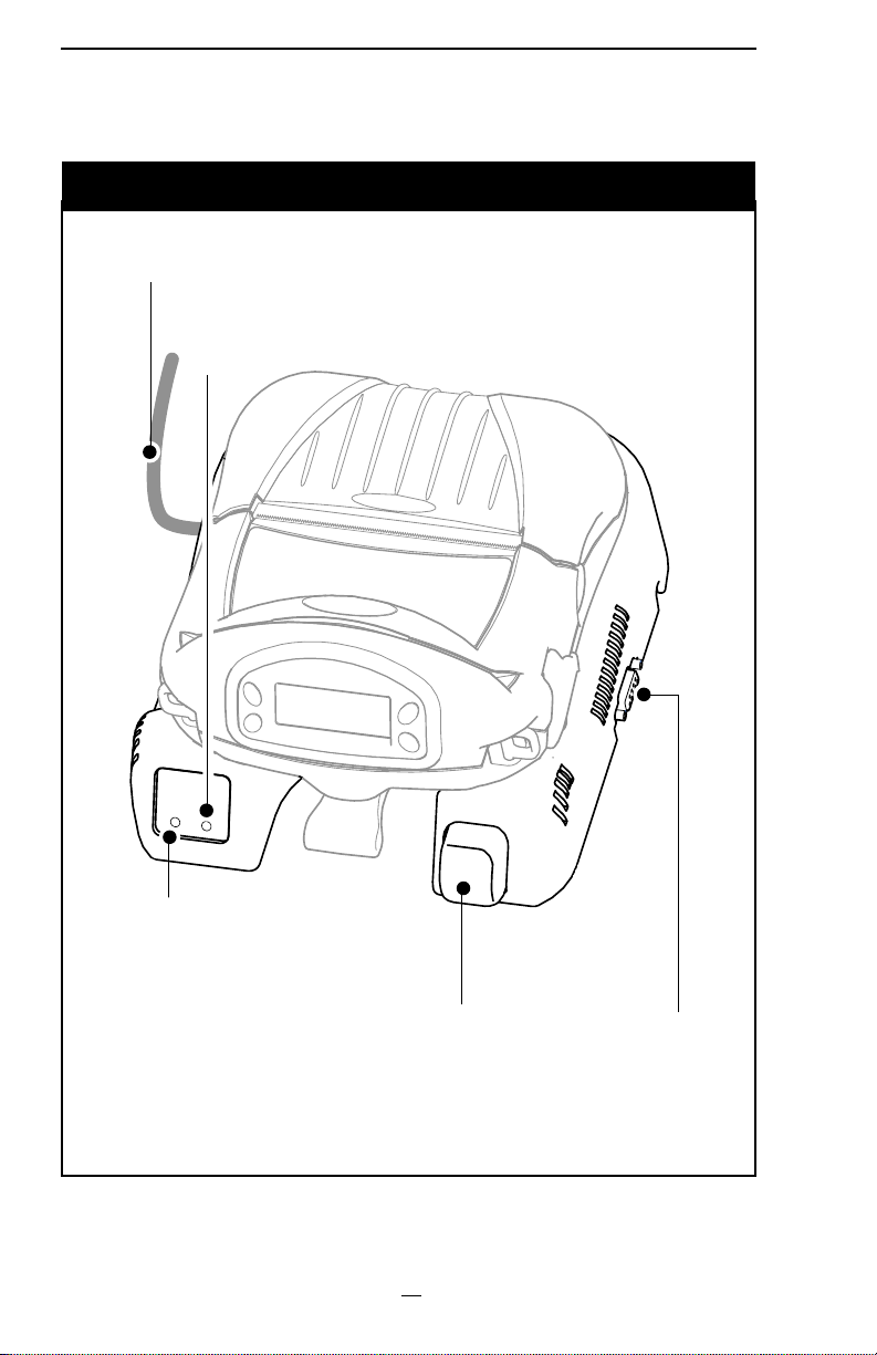
Figure 1: Vehicle Cradle with RW 420 Printer Installed
Input Power Cable
Power Indicator
Always Green when
power is on
Charge Indicator
Steady Amber
indicates charging
Steady Green
indicates charging is
complete
Alternating Amber
and Green indicates
battery fault condition
RW 420 Vehicle Cradle Installation Guide
Latch Release
Button
Press to release
Printer from Cradle
6
RS232 I/O
Connector
Page 7

Required for Installation
• An electrical drill, 1/4”(6 mm) drill bit
• Common hand tools.
• #8-32 Screws or Bolts and appropriate mounting hardware
for securing the Vehicle Cradle
Note: Use of appropriate hardware used to secure the Vehicle Cradle to the
vehicle is the responsibility of the installer
Reference
• RW 420 User’s Guide
Contents of the Package
• The RW 420 Vehicle Cradle Assembly
• One of two power input cables: either (1) an unterminated
cable with an integrated fuse holder, or (2) a cable terminated
with a cigarette lighter adapter.
• Hardware for routing and securing the input power cable.
• This Guide
Installation
Introduction to Installation
The RW 420 Vehicle Cradle allows you to mount a RW 420 printer
into virtually any vehicle with an electrical system voltage range of
9 to 30 VDC. The installation kit provided with the Cradle includes
an input power cable which, when connected to the vehicle’s electrical system, provides power to run the Printer and charge its battery.
The input power cable is wired to the vehicle’s battery power system indirectly through a power take-off point. One version of the
Vehicle Cradle supplies an input power cable that can be plugged
into an automotive vehicle’s cigarette lighter.
CAUTION: Under no circumstances should this equipment be attached di-
rectly to the vehicle’s battery without a proper fuse.
Since each situation or equipment type may pose unique requirements, mounting hardware selection and mechanical installation
shall be the responsibility of the installer. Zebra recommends using self-locking (ESN) nuts, bolts, and/or lock washers for installing
the mount. The Cradle is secured with #8-32 mounting hardware
(4 places).
Note: Hardware used to secure the Vehicle Cradle to the vehicle is not
supplied in the installation kit.
Your tasks are to:
• Mechanically prepare and install the RW 420 Vehicle Cradle
RW 420 Vehicle Cradle Installation Guide
7
Page 8

Figure 2: Vehicle Cradle Installation Dimensions
(RW 420 Printer Installed)
4.3”
[109 mm]
8.0”
[203 mm]
7.0”
[179 mm]
0.3”
[7 mm]
5.5”
[140 mm]
Dimensions
shown are for an
RW 420 with the
MSR/SmartCard option.
9.7”
[246 mm]
3.5”
[89 mm]
RW 420 Vehicle Cradle Installation Guide
5.5”
[140 mm]
8
1.19” [30 mm]
1.5”
[38 mm]
#8-32 X .38”
deep. (x4)
Page 9

• Connect the power input cable from the vehicle’s electrical system and the data I/O cable from the data terminal (if
used).
It is important to leave a free zone around the printer to allow
loading of paper and routine cleaning of the print head. Refer to
Figure 2.
If you are installing the optional mounting arm, remember the
arm provides a considerable range of movement for the Cradle and
Printer. This allows adjustment to the best position for the operator. Extra clearance should be provided for this movement if it is
desired in the installation. Refer to pages 18-20 for more information on installing the Cradle using the Mounting Arm.
Some models of the RW 420 will have a Magnetic Stripe Card
reader and a SmartCard reader installed. If these features are to
be used, the printer must be located so that the operator will have
clear access to the reader’s slots for these cards. Refer to the RW
420 Users Guide for more information on the use of the Magnetic
Strip Reader/SmartCard reader features.
Decide where you will mount the printer, and proceed with the
following instructions.
CAUTION: Mount the Printer and Vehicle Cradle where it will not hit the op-
erator in case of an accident.
Vehicle Cradle Preparation
Plan your installation with the above considerations in mind, and
locate the Printer and Vehicle Cradle so that the operator can easily load printing media, operate the printer’s controls and perform
routine maintenance such as cleaning the printhead. Follow these
steps:
1. Select a location in the vehicle that will avoid personal con-
tact in case of an accident.
2. Turn the Cradle upside down, and plug the input power cable
into the bottom of the Cradle.
3. Route the input power cable out of the Cradle. Note that
there are retaining features in the Cradle to keep the cable in
place. Refer to Figure 3.
4. Once the Cable has been located, secure it to the Cradle with
the cable clamp supplied with the installation kit. Use the
self-tapping screw and flat washer supplied in the kit to attach the clamp to the Cradle.
5. Make sure that the input power cable routing does not invite
damage to the cable. To avoid unintentional contact between
the wire and any sharp edges, provide the cable with proper
bushings and clamping where it passes through openings.
continued on pg. 11
RW 420 Vehicle Cradle Installation Guide
9
Page 10

Figure 3: Input Power Cable Routing
Plug Input
Power Cable
into Cradle
RS232 I/O Connector
Cable Clamp
Secure with supplied
hardware
RW 420 Vehicle Cradle Installation Guide
10
Page 11

6. Route the input power cable to the vehicle’s power take-off
point you will be using. Use the supplied adhesive-backed
clamps to secure the cable along its entire length.
Input Power Cable Completion
There are two power cable options that can be used with the
Vehicle Cradle. One terminates in a (fused) cigarette lighter adapter. The other terminates in bare wire and is intended for direct wiring into the vehicle electrical system. This second option has an
in-line fuse holder near the end of the cable that connects to the
vehicle electrical system.
If you are using a Vehicle Cradle with the cigarette lighter plug, all
you need to do is plug the power cable into a the vehicle’s cigarette
lighter socket. The cable must be secured along its entire length
and must not be allowed to hang loose, as described in the section
“Secure the Power Cable”, below
If you are using the cable that terminates in bare wire, the directions are as follows:
• You must not cut the cable shorter as this will cut off the inline fuse holder. If there is extra length bundle the cable securely to eliminate the excess.
CAUTION: There must be a fuse between the vehicle’s power source and
the input power cable connection! If you are not using the cable supplied
with the Vehicle Cradle, selecting the size and rating of this fuse is the installer’s responsibility.
• The installer must find the nearest practical connection point
to the vehicle’s main battery voltage. Consult the vehicle
manufacturer or a dealer to determine the best power connection location. Note that the vehicle wiring leading to the
connection point must be at least 18 AWG. Note also that
many vehicles use SAE wiring gage, which is different from
AWG.
Prepare the Cable Ends:
NOTE: Actual cable termination used must be compatible with the power
source. The following is a guideline.
1. Strip 1/4” (6 mm) of insulation from the BLACK wire.
2. Securely crimp the supplied 3/8” terminal ring onto the
BLACK wire.
3. Strip 1/4” (6 mm) of insulation from the RED wire.
4. Securely crimp the supplied 3/8” terminal ring onto the RED
wire.
Connect Cable to the Power Source
1. Ensure that cable terminals are well connected to the cable.
2. Connect black cable ground (-) terminal to vehicle ground location.
RW 420 Vehicle Cradle Installation Guide
11
Page 12

3. Connect red cable power (+) terminal to vehicle power
source.
Secure the Power Cable
Secure the Input Power along its entire length with the supplied
adhesive-backed clamps.
. Make sure that the cable routing does not interfere with other
equipment or vehicle controls. Insure that the cable routing protects the cable from damage during vehicle use.
Using the Printer in the Vehicle Cradle
Printer Preparation
Prepare the printer for installation into the Vehicle Cradle by doing the following:
It is strongly recommended as a safety precaution that the adjustable
shoulder strap be removed prior to docking the Printer. This precaution will
ensure the strap will not interfere with proper operation of the vehicle.
• Always install the Battery prior to mounting the printer in the
Cradle.
• Remove the Docking Connector Cover from the bottom of
the printer, and retain it for future use. (Refer to Figure 4)
Figure 4: Printer Preparation
RW 420 Vehicle Cradle Installation Guide
12
Remove and retain the Docking
Connector Cover
and attaching
Hardware
Page 13

Figure 5: Installing the Printer In The Vehicle Cradle
Rock the Printer into the
Cradle to latch it in position.
Place the Printer
over the retaining
pins in the Cradle.
Printer Installation
The RW 420 Printer can now be installed in the Vehicle Cradle:
• Place the bottom of the printer over the two pins in the
Cradle.
• Rotate the Printer into the Cradle and press firmly until it
latches in place.
• Turn the vehicle’s power source for the Cradle on, and verify that the power indicator light and the charger light on the
Cradle’s front panel are lit.
If the charge indicator does not light up, unlatch the printer from the
Vehicle Cradle, lift it clear from the Cradle and reseat it.
• Turn the printer on and print a configuration label to verify
that the printer is functioning properly. Refer to the RW 420
User’s Guide for instructions on printing a configuration label.
RW 420 Vehicle Cradle Installation Guide
13
Page 14

Figure 6: Removing the Printer from the Vehicle Cradle
Press the
Latch Button
to release
the Printer.
Rotate the Printer out of the
Cradle.
Lift the printer free
of the retaining
pins.
Removing the Printer
Remove the Printer by doing the following:
• Turn the Printer off.
• If the Printer is directly connected to a communications ca-
ble, unplug and remove the cable from the Printer.
• Press the latch release button on the Vehicle Cradle and pivot
the Printer out of the Cradle.
• If you will be using the Printer out of the Vehicle Cradle for a
prolonged period, replace the Docking Connector Cover on
the Printer.
Loading Media
Using the Printer’s Internal Media Supply
If you are using the Printer’s internal media compartment, follow
the loading procedures found in the RW 420 User’s Guide.
RW 420 Vehicle Cradle Installation Guide
14
Page 15

Using an External Media Supply
If the printer’s media supply is from an external supply, typically fanfold media, you must make provisions for a media bin to be
positioned to allow media to enter the printer through either the
bottom or the back of the Vehicle Cradle. If the Cradle is mounted
against a vertical surface there is a slot and guiding features in the
base to insure the media will feed properly into the printer.
If you are using an external media supply follow these steps to
load media:
1. Open the RW 420’s media supply compartment.
2. Load the media from the external supply through the feed
slots in the bottom of the Cradle and the Printer and past the
printhead. Note that if you are using 4 inch (10.16 cm) wide
external media, you can install the Fanfold Spacer (Zebra
p/n BA16625-1) between the printer’s media supports to keep
them from binding on the edges of the media.
3. Close and latch the media compartment.
NOTE: Your printer must be configured with the External Media option to use
an external media supply. If using an external media supply bin, ensure no
extra items are suspended from either the Printer or the Vehicle Cradle.
Printer Access
The media compartment and operator controls can be reached
while the printer is secured in the Vehicle Cradle.
If you need to remove the printer for servicing follow the removal
procedure detailed above in the Printer Installation and Removal
section.
Vehicle Cradle Indicators
The Vehicle Cradle has two LED indicators on the front panel as
shown in Figure 1. The power LED is green when power is supplied
to the Cradle.
The Charge LED will display different colors depending on three
conditions:
• Steady amber indicates the printer battery is being charged.
• Steady green indicates that charging is complete.
• Alternate flashing green and amber indicates a fault condition with the printer battery.
A fault condition could be caused by the battery’s internal temperature exceeding its specified limits (too hot or too cold) or
could be caused by an internal short in the battery. Allow the battery to return to ambient temperature and try to recharge. If the
fault condition persists, discontinue use of that battery.
If the charge indicator does not light up when the printer is installed, it may
be the result of one of two possible conditions:
continued
RW 420 Vehicle Cradle Installation Guide
15
Page 16

1) The printer is not seated properly in the cradle. Unlatch and redock the
printer into the cradle. Observe if charge indicator lights.
2) If redocking the printer does not cause the charge light to turn on, it is
because the cradle has entered a prequalification process with the printer’s
battery. This process may last up to 22 minutes. At the end of the 22 minutes
the cradle will either: (1) commence charging or (2) display a charge error
(flashing LED) which denotes a faulty battery.
Connections to a Terminal
Communications with a Terminal
If you are also installing a terminal in the vehicle, consult the terminal manufacturer’s literature for installation instructions. If the
terminal and Printer will communicate using either an RS232 or
USB cable, use shielded cables and keep their length as short as
possible. Ensure the routing of the cable does not invite damage to
the cable or interfere with the control or use of the vehicle.
If the printer is communicating by means of the RS232 protocol, you have the option of plugging a communications cable into
the connector on the Vehicle Cradle, or directly into the Printer.
Connecting directly to the RS232 port of Printer requires the use of
a special communications cable with a built-in locking strain relief.
If you are communicating by means of USB, you must plug the
USB communications cable directly into the Printer using a special
communications cable with a built-in locking strain relief.
Consult the factory for information on the various I/O data cables
offered by Zebra for use with a variety of widely used terminals.
NOTE: This unit was tested with shielded cables on the peripheral devices.
Shielded cables must be used with the unit to insure compliance.
If the terminal and the Printer will communicate via an RF link, it
is the installer’s responsibility to test the strength and reliability of
such a link prior to final installation.
Power Connections to a Terminal
If you are also installing a terminal in the vehicle, you must run
two separate cables from the vehicle power source: one to the
printer and one to the terminal.
Warning: Do not attempt to power both devices from the same power ca-
ble.
The terminal power cable must be either supplied by the terminal
manufacturer or fabricated by the installer.
It is the installer’s responsibility to determine the suitability of
running a terminal from the vehicle’s battery.
NOTES: This Installation Guide does not cover the installation of any terminal
used in conjunction with the RW 420 Printer or Vehicle Cradle.
Zebra Technologies Corporation is not liable for personal injury or damage
to equipment caused by improper installation to any power source.
RW 420 Vehicle Cradle Installation Guide
16
Page 17

Installing the Mounting Arm
Description
An optional mounting arm (Zebra p/n AK17463-002) is offered for
use with the Vehicle Cradle which allows a more versatile method
of positioning the RW 420 printer. It consists of an arm with a ball
and socket joint at either end, which in turn are terminated with a
mounting flange. One flange is secured to the Cradle by the four
mounting holes provided on the bottom plate, and the other is secured to the desired mounting surface. A clamp on the arm locks
the Cradle in the desired position.
Installation
CAUTION: Mount the Printer and Vehicle Cradle where it will not hit the op-
erator in case of an accident.
Warning: Do not connect the input power cable to the Vehicle Cradle until
the Cradle and Mounting Arm installation have been completed.
For ease of installation, the Arm can be disassembled by loosening the clamp enough to remove the two ball and socket flanged
ends. These end flanges can then be easily secured to the Vehicle
Cradle and the desired mounting surface. Then the arm can be
slipped over the two ends and the clamp tightened to secure the
Cradle in position.
When installing the mounting arm, remember that the arm provides a considerable range of movement for the Vehicle Cradle
and Printer. Extra clearance should be provided for this movement
if it is desired in the installation.
Some models of the RW 420 will have a Magnetic Stripe Card
reader and a SmartCard reader installed. If these features are to
be used, the printer must be located so that the operator will have
clear access to the reader’s slots for these cards. Refer to the RW
420 Users Guide for more information on the use of the Magnetic
Strip Reader/Smartcard reader features.
Mounting Hardware
Mounting hardware is supplied with the Mounting Arm Kit. The
#8-32 x 1/2” Screws should be used to secure one end of the arm
to the bottom of the Vehicle Cradle. The #10-24 x 3/4” Screws and
associated hardware may be used to secure the other end of the
arm to the desired mounting surface.
Vehicle Cradle Preparation
Refer to the section on Vehicle Cradle Preparation earlier in this
manual for more specific instructions and illustrations on securing the power cable to the Cradle. Locate the Printer and Cradle so
when installed with the Mounting Arm the operator can easily load
RW 420 Vehicle Cradle Installation Guide
17
Page 18

Figure 7: Optional Mounting Arm Dimensions
7.35”
[187 mm]
2.43” [62 mm}
R .91” [23 mm}
1.19” [30 mm}
1.50” [38 mm}
Figure 8: Securing the Vehicle Cradle to the Mounting Arm
Vehicle Cradle
Use #8 hardware
supplied with
kit to secure to
Cradle
Tightening Clamp
Use #10 hardware
supplied with
kit to secure to
mounting surface
RW 420 Vehicle Cradle Installation Guide
18
Page 19

printing media, operate the printer’s controls and perform routine
maintenance such as cleaning the printhead. Follow these steps:
1. Select a location in the vehicle that will avoid personal con-
tact in case of an accident.
2. Turn the Cradle upside down, and plug the input power cable
into the bottom of the Cradle.
• Route the input power cable out of the Cradle. Note that it
can be routed out either side of the Cradle and that there are
retaining features in the Cradle to keep the cable in place.
Refer to Figure 3.
• Be sure to leave enough slack in the power cable to allow
the Mounting Arm to pivot freely without putting strain on
the power connections.
• Make sure that the input power cable routing does not invite damage to the cable when the Vehicle Cradle is pivoted.
3. Once the cable routing has been determined, secure it to the
Vehicle Cradle with the cable clamp(s) supplied with the installation kit. Use the self-tapping screws and flat washers
supplied in the kit to attach the clamp to the Cradle.
4. Secure one of the mounting flanges from the movable Arm
to the bottom of the Vehicle Cradle with the (4) #8-32 x 1/2”
Screws supplied with the Mounting Arm.
5. Secure the other mounting flange on the Movable Arm to
the desired mounting surface. You can use the #10-24 x 3/4”
Screws and associated hardware supplied in the Mounting
Arm Kit or use other hardware as the mounting conditions
dictate.
Input Power Completion
Route the input power cable per the earlier section in this Guide:
“Input Power Cable Completion.”
RW 420 Vehicle Cradle Installation Guide
19
Page 20

Technical Support
U.S. ONLY
Zebra maintains a help line for questions involving installation
and use of the RW 420 Vehicle Cradle.
Please have as much information as possible regarding your
particular application ready when you call to enable the technical support personnel to help you. The number in the U.S. is
(800)-423-0442 and is open Monday through Friday from 8:00 am
to 4:30 P.M. E.S.T.
ALL OTHERS
For Technical Support please contact your local Zebra sales representative listed below:.
Zebra Technologies Europe Limited
Zebra House
The Valley Centre, Gordon Road
High Wycombe
Buckinghamshire HP13 6EQ, UK
Phone: +44.1494.472872
Fax: +44.1494.450103
Zebra Technologies
Latin American Sales Office
9800 NW 41Street
Suite 220
Doral, Florida 33178 USA
Phone: +1.305.558.8470
Fax: +1.305.558.8485
Zebra Technologies Asia Pacific, LLC
16 New Industrial Road
#05-03 Hudson TechnoCentre
Singapore 536204
Phone: +65-6858 0722
Fax: +65-6885 0838
 Loading...