

Page 1
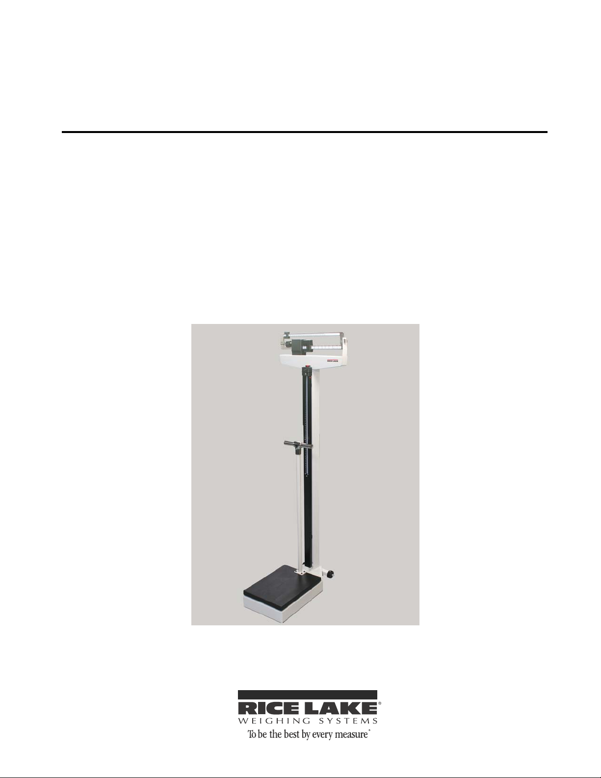
Rice Lake Mechanical Physician Scale
(w/ hand post)
Model RL-MPS-30
Operation Instructions
132702
Page 2

Page 3

Contents
Technical training seminars are available through Rice Lake Weighing Systems.
Course descriptions and dates can be viewed at www.ricelake.com or obtained
by calling 715-234-9171 and asking for the training department
1.0 Introduction.................................................................................................................................. 1
2.0 Installation Instructions............................................................................................................... 2
2.1 Pillar Installation . . . . . . . . . . . . . . . . . . . . . . . . . . . . . . . . . . . . . . . . . . . . . . . . . . . . . . . . . . . . . . . . . 2
2.2 Steelyard Rod Connection . . . . . . . . . . . . . . . . . . . . . . . . . . . . . . . . . . . . . . . . . . . . . . . . . . . . . . . . . 4
2.3 Height Rod Installation . . . . . . . . . . . . . . . . . . . . . . . . . . . . . . . . . . . . . . . . . . . . . . . . . . . . . . . . . . . . 5
2.4 Wheel Installation . . . . . . . . . . . . . . . . . . . . . . . . . . . . . . . . . . . . . . . . . . . . . . . . . . . . . . . . . . . . . . . . 6
3.0 Hand Post Installation.................................................................................................................. 7
4.0 Zero Adjustment........................................................................................................................... 8
5.0 Weighing a Patient .......................................................................................................................9
6.0 Troubleshooting ........................................................................................................................... 9
7.0 Specifications.............................................................................................................................. 9
© 2012 Rice Lake Weighing Systems. All rights reserved. Specifications subject to change without notice.
Rice Lake Weighing Systems is an ISO 9001 registered company
November 2012
Page 4

Rice Lake continually offers web-based video training on a growing selection
of product-related topics at no cost. Visit www.ricelake.com/webinars.
Page 5
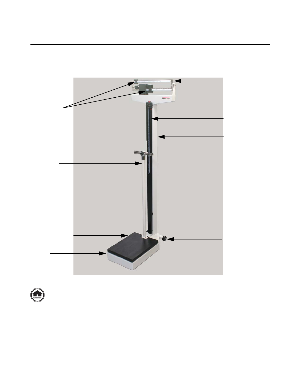
1.0 Introduction
Weigh beam
Poise weights
Height rod
Pillar
Hand post
Moveable wheels
Platform/Scale base
Frame
Intern et
The Rice Lake Mechanical Physician Scale is ideal for height and weight measurement. The scale is durable,
having a slip resistant plastic cover, a retractable aluminum height rod, a hand post, and rear wheels. These
installation and operating instructions will guide the user through basic instructions on pillar assembly, wheel
installation, pillar height rod installation, hand post installation, and the zero adjustment of the scale.
Figure 1-1. Mechanical Physician Scale Parts Breakdown
This manual can be viewed and downloaded from the Rice Lake W eighing Systems web site
at www.ricelake.com/health. Rice Lake Weighing Systems is an ISO 9001 registered
company.
1
Page 6
2.0 Installation Instructions
Remove cable tie from steelyard rod
Remove twisty
ties from scale
parts
You will receive your Mechanical Physician Scale partially assembled. Those items that need additional
assembly are:
• Pillar assembly
• Steelyard rod connection
• Height rod installation
• Wheel installation
• Hand post installation
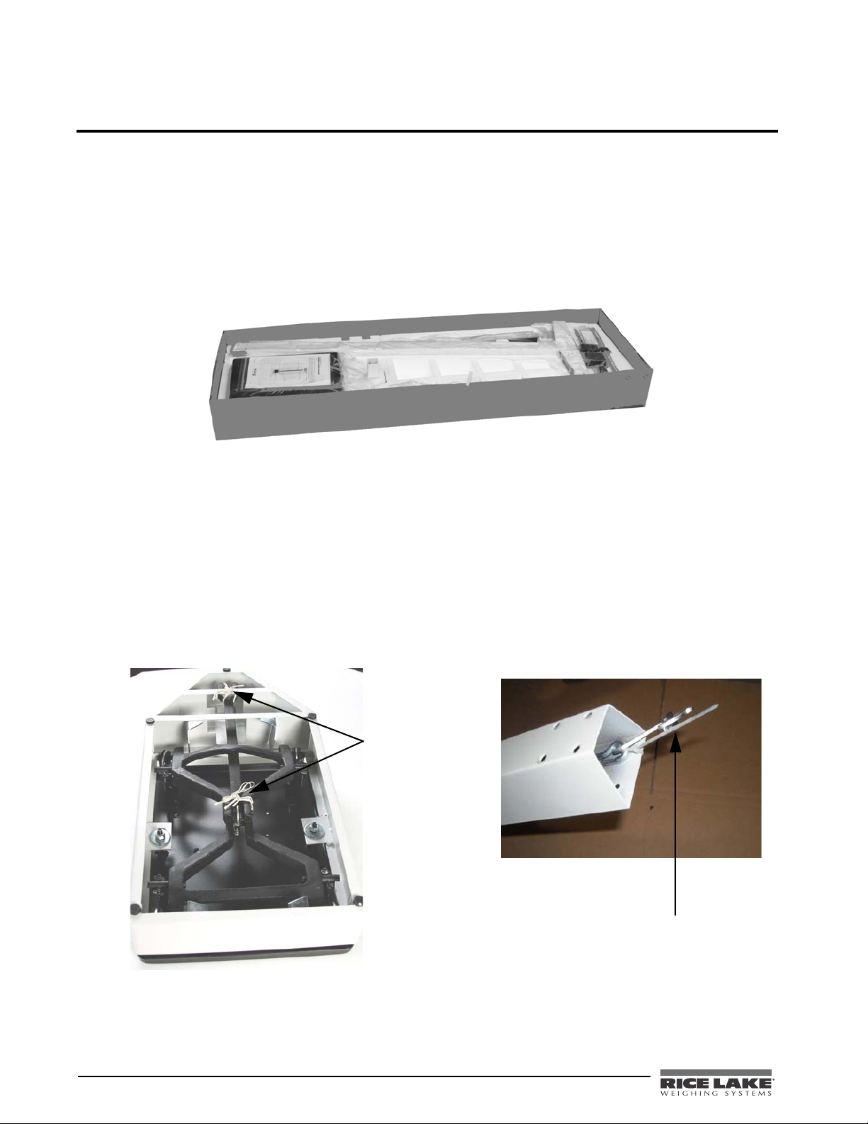
Remove all components from the shipping box (shown in Figure 2-1) and lay out in a convenient place.
Figure 2-1. Box Contents
2.1 Pillar Installation
Prior to assembly, you’ll need the following tools to finish assembling the Mechanical Physician Scale.
• Multi-purpose tool (included)
• Wrench (included)
The pillar comes separate from the scale base and must be attached prior to use. Use the following steps to attach
the pillar to the scale base.
1. Set the scale base on a table or other convenient place.
2. Remove the twisty ties off the scale base as shown on the left hand side of Figure 2-2. Remove the cable
tie that holds the steelyard rod from shifting during transit (shown on right hand side of Figure 2-2).
Figure 2-2. Remove Twisty Ties and Cable Ties
2 Mechanical Physician Scale Installation and Operation Instructions
Page 7

3. Insert the pillar into the scale base assembly ensuring that the RLWS logo located on the weight beam
faces the
scale base.
Figure 2-3. Attach the Pillar to the Scale Base
4. Using the wrench provided, insert and tighten the eight bolts and washers to secure the pillar to scale
base.
Figure 2-4. Attach Eight Bolts and Washers to Secure the Pillar to the Scale Base
Mechanical Physician Scale Installation and Operation Instructions - Installation Instructions 3
Page 8

2.2 Steelyard Rod Connection
Note
Force lever
assembly linkage
must be properly
aligned in order to
weigh properly.
The steelyard rod is located inside the scale pillar. Once the pillar is attached to the scale base, the steelyard rod
must be attached to the bottom of the scale.
1. Lay the scale pillar on a table so that the scale platform hangs over the edge of the table and allows you
to access the bottom of the scale.
Figure 2-5. Connecting the Steelyard Rod to the Scale Base
2. Insert the hook part of the multi-purpose tool (included and shown above) to the small hole in the bottom
of the steelyard rod, and pull the hook of the steelyard rod with the hook of the multi-purpose tool to
connect it to the scale base lever as shown in
head, and hook the bearing of the steelyard rod on the pivot of the long lever.
Visually ensure that the force lever assembly linkage is centered and properly aligned. Occasionally
during shipping, alignment will become skewed. The linkage must be free floating in order for the scale
to weigh properly. The linkage can be seen by looking up underneath the top weigh beam if the scale is
slightly tipped to one side.
Figure 2-5, then push the scale base lever towards the pillar
Figure 2-6. View Looking up at Linkage up Underneath the Top Weigh Beam
3. Place the scale gently back on the floor.
4 Mechanical Physician Scale Installation and Operation Instructions
Page 9

2.3 Height Rod Installation
Slotted holes
Press red button to raise
or lower height rod.
The Mechanical Physician Scale comes with a height rod. Use the following steps to install the height rod.
1. Insert the back side slotted holes of the height rod into the two bolts on the front side of the pillar as
shown in
.
Figure 2-7. One is located at the top of the pillar and the other towards the bottom of the pillar.
Figure 2-7. Attach the Slotted Screw Location onto the Pillar Bolt Location
2. Use the enclosed wrench to tighten the two stainless steel hex-head screws, but ensure not to over
tighten.
3. To raise or lower the height rod, press the red button at the top of the height rod and raise up or down.
Figure 2-8. Height Rod Button
Mechanical Physician Scale Installation and Operation Instructions - Installation Instructions 5
Page 10

2.4 Wheel Installation
Note
To p
Bottom
The Mechanical Physician Scale comes with sturdy wheels for easy portability. To install the wheels onto the
scale, use the following instructions.
Mounting the wheels upside down can create scale errors.
1. Align the angle iron of the wheel base to the scale platform as shown in Figure 2-9.
Figure 2-9. Attach the Scale Wheels onto the Scale Base
2. Use the screws and washers that are included with the scale to fix the wheel to the platform, adjusting the
angle iron at a level position, then tighten screws.
3. When moving the scale, hold the two side faces of the pillar to keep the front side of the platform away
from the ground.
Figure 2-10. Wheels Offer Easy Portability
6 Mechanical Physician Scale Installation and Operation Instructions
Page 11

3.0 Hand Post Installation
Warning
The Rice Lake Mechanical Physician scale comes with a hand post to add in balancing a patient while on the
scale. Use the following steps to install the hand post to the scale.
1. Unscrew the four hex head screws from the scale base and set the screws and washers aside.
Figure 3-1. Unscrew Hex Head Screws From Scale Platform
2. Position the hand post over the screw holes on the scale platform making sure that the washer is set
between the hand post base and the screw.
Figure 3-2. Position Hand Post
3. Tighten all four hex head screws with the wrench that has been provided.
Figure 3-3. Tighten Hex Head Screws
Do not attempt to transport the scale by the hand post. Serious injury could occur to the
scale and to the operator.
Mechanical Physician Scale Installation and Operation Instructions - Hand Post Installation 7
Page 12

4.0 Zero Adjustment
Zero
adjusting
screw
Weigh beam
Scale pointer
Eye loop area
Poise Weights
T o ensure accurate weighments, a zero adjustment should be done to the scale upon arrival and setup. To perform
a zero adjustment, carry out the following steps.
1. Ensure the scale is sitting on a level surface.
2. Make sure that the poise weights are pushed all the way to the left hand side (at zero) making sure that
the large poise is firmly seated in the notch and the small poise is firmly against the shoulder of the
beam.
3. Check the eye loop area of the scale to ensure that the scale pointer is equally balanced between the eye
loop area.
Figure 4-1. Eye Loop Area and Zero Adjusting Screw Location
4. If the scale is not balancing properly, then the small zero balance weight must be adjusted. Turn the zero
adjusting screw (shown in Figure 4-1) using a flat head screwdriver. By adjusting the screw, the zero
balance weight will move accordingly.
Figure 4-2. Zero Adjusting Screw Location
8 Mechanical Physician Scale Installation and Operation Instructions
Page 13

5.0 Weighing a Patient
To weigh a patient, have the patient step onto the scale platform and slide the larger poise (shown on bottom) to
the approximate target weight. Next move the smaller poise on top until the weigh beam balances and the scale
pointer is centered within the eye loop area as shown in
Figure 4-1.
6.0 Troubleshooting
For the most accurate weight, always use the scale on a hard, level surface and stand in the center of the platform
with the weight distributed as evenly as possible. If an error occurs or seems excessive, check the following:
Problem Possible Fix
Zero balance of beam The weigh beam must be balanced so the pointer comes to a rest in the
center of the eye loop (shown in
at zero (see Figure 1-1 for poise weight location). Adjust the balance by
turning the zero adjusting screw at the left end of the weigh beam (see
Figure 4-1).
Beam does not move freely Check if the beam pointer is touching the side of the eye loop in its range of
travel.
Visually ensure that the linkage is centered and properly aligned. Occasionally
during shipping, the alignment will become skewed. The linkage must be free
floating in order for the scale to weigh properly. The linkage can be seen by
looking up underneath the top weigh beam if the scale is slightly tipped to one
side.
Platform rocks excessively When you push down on any corner of the platform, you should not feel any
significant rocking. Ensure scale is setting on a level surface.
Beam does not move at all during a weighment This can be caused by the poise weights being set to a higher weight than the
person’s actual weight. Reset the weights to a lower weight. Also check to
see that the steelyard rod is properly connected and aligned (see
Scale is out of calibration Recalibrate the scale by placing a known weight on the scale and moving the
zero adjusting screw to bring the scale back to zero.
Figure 3-1) when both poise weights are set
Figure 2-6).
7.0 Specifications
Maximum Capacity 180 kg
Graduation 0.1 kg
Height Rod Range 60-212 cm
Min. Value of Height per Division 0.1 cm
Platform Size 374.65 x 273.05 mm
Hand Post Height 80 cm
Table 6-1. Troubleshooting Guide
RL-MPS-30
Table 7-1. Model Specifications
Mechanical Physician Scale Installation and Operation Instructions - Weighing a Patient 9
Page 14

For More Information
Web Site
• http://www.ricelake.com/health
Contact Information
Hours of Operation
Knowledgeable customer service representatives are available 6:30 a.m. - 6:30 p.m. Monday through Friday and
8 a.m. to 12 noon on Saturday. (CST)
Telephone
• Sales/Technical Support 800-472-6703
• Canadian and Mexican Customers 800-321-6703
• International 715-234-9171
Fax
• Fax Number 715-234-6967
Email
• US sales and product information at prodinfo@ricelake.com
• International (non-US) sales and product information at intlsales@ricelake.com
Mailing Address
Rice Lake Weighing Systems
230 West Coleman Street
Rice Lake, WI 54868 USA
10 Mechanical Physician Scale Installation and Operation Instructions
Page 15

Mechanical Physician Scale Limited Warranty
Rice Lake Weighing Systems warrants that all RLWS equipment and systems properly installed by a Distributor
or Original Equipment Manufacturer (OEM) will operate per written specifications as confirmed by the
Distributor/OEM and accepted by RL WS. All systems and components are warranted against defects in materials
and workmanship for two years.
RLWS warrants that the equipment sold hereunder will conform to the current written specifications authorized
by RLWS. RLWS warrants the equipment against faulty workmanship and defective materials. If any equipment
fails to conform to these warranties, RLWS will, at its option, repair or replace such goods returned within the
warranty period subject to the following conditions:
• Upon discovery by Buyer of such nonconformity, RLWS will be given prompt written notice with a
detailed explanation of the alleged deficiencies.
• Examination of such equipment by RLWS confirms that the nonconformity actually exists, and was
not RLWS shall be the sole judge of all alleged non-conformities.
• Such equipment has not been modified, altered, or changed by any person other than RLWS or its
duly authorized repair agents.
• RLWS will have a reasonable time to repair or replace the defective equipment. Buyer is responsible
for shipping charges both ways.
• In no event will RLWS be responsible for travel time or on-location repairs, including assembly or
disassembly of equipment, nor will RLWS be liable for the cost of any repairs made by others.
THESE WARRANTIES EXCLUDE ALL OTHER WARRANTIES, EXPRESSED OR IMPLIED, INCLUDING WITHOUT
LIMITATION WARRANTIES OF MERCHANTABILITY OR FITNESS FOR A PARTICULAR PURPOSE. NEITHER
RLWS
RLWS AND BUYER AGREE THAT RLWS’S SOLE AND EXCLUSIVE LIABILITY HEREUNDER IS LIMITED TO
REPAIR OR REPLACEMENT OF SUCH GOODS. IN ACCE PT ING THIS WARRANTY, THE BUYER WAIVES ANY AND
ALL OTHER CLAIMS TO WARRANTY.
SHOULD THE SELLER BE OTHER THAN RLWS, THE BUYER AGREES TO LOOK ONLY TO THE SELLER FOR
WARRANTY CLAIMS.
NO TERMS, CONDITIONS, UNDERSTANDING, OR AGREEMENTS PURPORTING TO MODIFY THE TERMS OF THIS
WARRANTY SHALL HAVE ANY LEGAL EFFECT UNLESS MADE IN WRITING AND SI GNED BY A CORPORATE
OFFICER OF RLWS AND THE BUYER.
NOR DISTRIBUTOR WILL, IN ANY EVENT, BE LIABLE FOR INCIDENTAL OR CONSEQUENTIAL DAMAGES.
© 2012 Rice Lake Weighing Systems, Inc. Rice Lake, WI USA. All Rights Reserved.
RICE LAKE WEIGHING SYSTEMS • 230 WEST COLEMAN STREET • RICE LAKE, WISCONSIN 54868 • USA
Mechanical Physician Scale Installation and Operation Instructions - Specifications 11
Page 16

12 Mechanical Physician Scale Installation and Operation Instructions
Page 17

Page 18

PN 132702 11/12
 Loading...