

Page 1
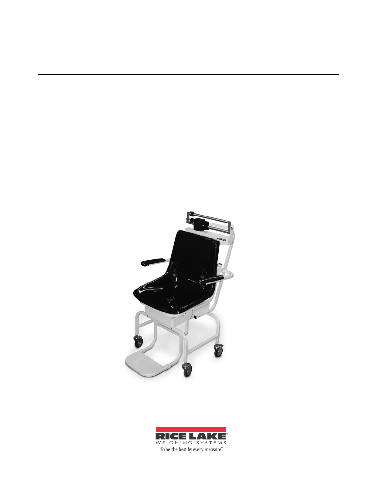
Rice Lake Mechanical Chair Scale
Model RL-MCS, RL-MCS-10
Operation Instructions
111372
Page 2

Page 3

Contents
Technical training seminars are available through Rice Lake Weighing Systems.
Course descriptions and dates can be viewed at www.ricelake.com or obtained
by calling 715-234-9171 and asking for the training department
1.0 Introduction................................................................................................................................. 1
2.0 Installation Instructions............................................................................................................... 2
2.1 Pillar and Beam Installation . . . . . . . . . . . . . . . . . . . . . . . . . . . . . . . . . . . . . . . . . . . . . . . . . . . . . . . . . 2
2.2 Steelyard Rod Connection . . . . . . . . . . . . . . . . . . . . . . . . . . . . . . . . . . . . . . . . . . . . . . . . . . . . . . . . . 3
2.3 Installing Transport Handle . . . . . . . . . . . . . . . . . . . . . . . . . . . . . . . . . . . . . . . . . . . . . . . . . . . . . . . . . 4
2.4 Seat and Footrest Installation . . . . . . . . . . . . . . . . . . . . . . . . . . . . . . . . . . . . . . . . . . . . . . . . . . . . . . . 5
2.5 Arm Rest Installation. . . . . . . . . . . . . . . . . . . . . . . . . . . . . . . . . . . . . . . . . . . . . . . . . . . . . . . . . . . . . . 6
3.0 Zero Adjustment........................................................................................................................... 8
For More Information ............................................................................................................................... 9
Chair Scale Limited Warranty ............................................................................................................... 10
© 2012 Rice Lake Weighing Systems. All rights reserved. Specifications subject to change without notice.
Rice Lake Weighing Systems is an ISO 9001 Registered Company. Model RL-MCS
October 2012
Page 4

Rice Lake continually offers web-based video training on a growing selection
of product-related topics at no cost. Visit www.ricelake.com/webinars.
ii Mechanical Chair Scale Installation and Operation Instructions
Page 5
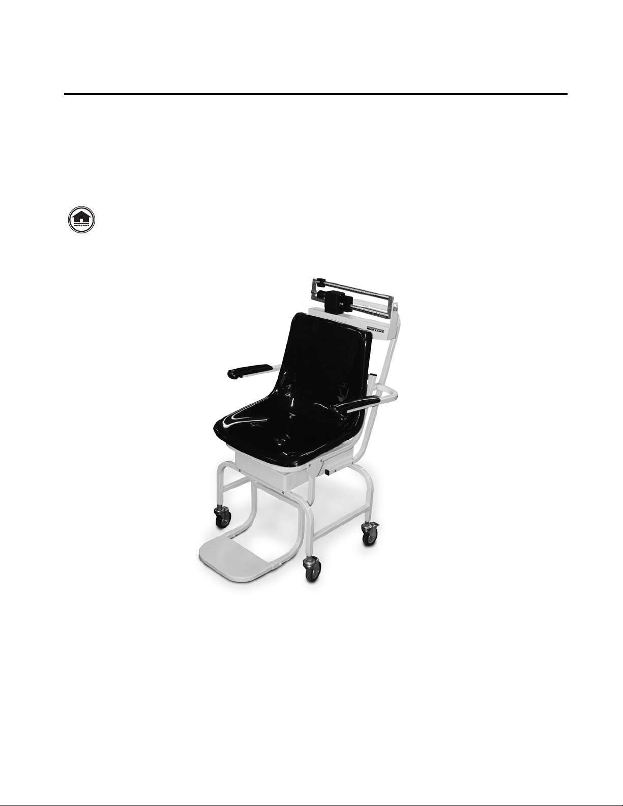
1.0 Introduction
Internet
The Rice Lake Mechanical Chair Scale is designed for the mobile challenged who have a difficult time standing
on a conventional scale. It is ideal for use in clinics and nursing facilities. The scale is durable, having a sturdy
enameled steel body, a durable molded plastic seat, heavy-duty footrest, and heavy-duty caster wheels for easy
portability
The Rice Lake Mechanical Chair Scale comes in two models:
• RL-MCS: lb/kg (440 lb (200 kg) capacity)
• RL-MCS-10: lb only (450 lb capacity)
This manual can be viewed and downloaded from the Rice Lake Weighing Systems web site
at www.ricelake.com/health. Rice Lake Weighing Systems is an ISO 9001 registered
company.
Figure 1-1. Mechanical Chair Scale
1
Page 6

2.0 Installation Instructions
Beam
Pillar
Push down on latching
assembly to lock
wheels and prevent
scale from rolling.
You will receive your Mechanical Chair Scale partially assembled. Those items that need additional assembly
are:
• Pillar and beam assembly to scale base
• Steelyard rod connection
• Transport handle onto scale base
• Seat and footrest installation
• Arm rest installation
Remove all components from the shipping crate and lay out in a convenient place.
2.1 Pillar and Beam Installation
The pillar and beam comes separate from the scale base and must be attached prior to use.
Use the following steps to attach the pillar and beam to the scale base.
1. Have the scale sitting on the floor in an area that allows you to work freely.
2. Lock casters on the frame to eliminate the unit from rolling while assembling the scale.
Figure 2-1. Pillar and Beam Components
Figure 2-2. Lock Casters to Keep From Rolling
2 Mechanical Chair Scale Installation and Operation Instructions
Page 7

3. Remove the eight screws from the scale base using a Phillips head screwdriver (as shown in the left hand
Steelyard rod (not
shown)
Steelyard rod
hook
photo) and set screws aside in a safe place.
Figure 2-3. Remove Screws From Scale Base and Insert Pillar and Beam into Scale Base Assembly
Insert, but don’t fasten the pillar and beam into the scale base assembly as shown in Figure 2-3 (right hand
side photo).
2.2 Steelyard Rod Connection
The steelyard rod is located inside the pillar. Remove the wire tie(s) holding the steelyard rod during
shipment. Insert the pillar into the base. Once the pillar is inserted to the scale base, the steelyard rod must be
attached to the bottom of the scale. The two photos in
photo of the ring in the scale bottom. Latch the hook onto the D-shaped ring shown in the right hand side picture.
Figure 2-4 show the hook of the steelyard rod and an inside
Figure 2-4. Attach The Steelyard Rod To the Scale Base D-Ring
Fasten the eight screws once the pillar and beam is connected to the scale base and the steelyard rod is hooked.
Figure 2-5. Insert and Tighten The Eight Screws
Mechanical Chair Scale Installation and Operation Instructions - Installation Instructions 3
Page 8

2.3 Installing Transport Handle
Transport handle
Side screws x 4
Once the pillar and beam are attached to the scale support frame and secured, it’s time to attach the transport
handle to the scale support frame (transport handle is illustrated in
1. Remove the four side screws (two on each side as shown in left hand side of Figure 2-6) from the scale
support frame and set aside. The transport handle will attach to the scale support frame using those
screws.
Figure 2-6. Transport Handle Installation
Figure 2-6).
2. Insert the transport handle into the two sides of the scale support frame (shown in right side of
Figure 2-6).
3. Insert and tighten the four screws using a Phillips screwdriver as shown in Figure 2-7.
Figure 2-7. Insert and Tighten Four Screws for Securing the Transport Handle to the Scale Support Frame
The transport handle should fit snuggly against the scale support frame.
4 Mechanical Chair Scale Installation and Operation Instructions
Page 9

2.4 Seat and Footrest Installation
Four screws on scale support
frame - only one screw
shown
Remove four screws from chair
frame (two on each side) and tilt the
chair upwards before installing
footrest assembly.
Once the transport handle is attached the next step is to install the molded seat to the scale support frame.
1. Remove the four screws from the movable scale support frame platform and set aside.
Figure 2-8. Removable Screws on The Movable Scale Support Frame
2. Set the chair onto the scale support frame platform but do not fasten the screws as the footrest assembly
will also have to be put into place prior to tightening all screws.
3. Remove screws from the chair frame (shown in Figure 2-9) and set aside.
4. Tilt the chair upwards as shown in Figure 2-9. This will allow the installer to get the footrest assembly in
place prior to securing the chair to the platform.
5. Slide the footrest assembly onto the chair scale base as shown in Figure 2-9.
Note that the footrest assembly for the footrest is hanging on the metal chair channel and lined up with
the screw holes on the channel of the chair scale frame as shown in
Figure 2-9. Tilt the Chair Upward Before Installing the Footrest Assembly
Figure 2-10.
Mechanical Chair Scale Installation and Operation Instructions - Installation Instructions 5
Page 10

Push footrest assembly back
so that the holes line up.
Secure screws (only one
shown)
Figure 2-10. Slide the Footrest Assembly So That Holes Line Up
Once the footrest is secured and the screws tightened for it, secure the molded seat onto the chair scale
frame.
6. Secure the four screws (shown below).
2.5 Arm Rest Installation
The last item to be installed on the mechanical chair scale are the two arm rests.
Use the following steps to attach the two arm rests to the mechanical chair scale molded seat.
6 Mechanical Chair Scale Installation and Operation Instructions
Figure 2-11. These Scr ews Hold The Molded Chair to the Scale Base
Figure 2-12. Detachable Arm Rest for the Mechanical Chair Scale
Page 11

1. Locate the bolt hole (x 4) location on the back of the molded chair.
two bolts for each arm rest
Figure 2-13. Hole Location and Four Bolts Used for Securing Arm Rest to Chair
2. Secure the arm rests to the molded chair using the four bolts (provided and shown in Figure 2-13), using
the 5mm allen wrench that’s been provided in this packaging.
Figure 2-14. Secure Arm Rests to the Molded Chair
3. The arm rests are now in position and can be moved up and down.
Figure 2-15. Arm Rests Are Secured to the Molded Chair Seat
Mechanical Chair Scale Installation and Operation Instructions - Installation Instructions 7
Page 12

3.0 Zero Adjustment
Eye Loop
Area
Zero
Adjusting
Screw
Scale pointer
T o ensure accurate weighments, a zero adjustment should be done to the scale upon arrival and setup. To perform
a zero adjustment, perform the following steps.
1. Ensure the scale is sitting on a level surface.
2. Check the eye loop area of the scale to ensure that the scale pointer is equally balanced between the eye
loop area.
Figure 3-1. Eye Loop Area and Zero Adjusting Screw Location (Lb/Kg model shown)
3. If the scale is not balancing properly, then the small zero balance weight must be adjusted. Turn the zero
adjusting screw (shown in Figure 3-1) using a flat head screwdriver. By adjusting the screw, the zero
balance weight will move accordingly.
4. The scale is now ready to weigh patients.
5. Have the patient sit down on the molded seat. The patient should be completely seated in the chair,
not leaning forward, and having feet firmly positioned on the footrest assembly.
8 Mechanical Chair Scale Installation and Operation Instructions
Page 13

For More Information
Literature
• Medical Scales - Mechanical Chair Scale, PN 114086
Web Site
• http://www.ricelake.com/medical
• http://www.ricelake.com/health
Contact Information
Hours of Operation
Knowledgeable customer service representatives are available 6:30 a.m. - 6:30 p.m. Monday through Friday and
8 a.m. to 12 noon on Saturday. (CST)
Telephone
• Sales/Technical Support 800-472-6703
• Canadian and Mexican Customers 800-321-6703
• International 715-234-9171
Fax
• Fax Number 715-234-6967
Email
• U.S. sales and product information at prodinfo@ricelake.com
• International (non-U.S.) sales and product information at intlsales@ricelake.com
Mailing Address
Rice Lake Weighing Systems
230 West Coleman Street
Rice Lake, WI 54868 USA
Mechanical Chair Scale Installation and Operation Instructions - Zero Adjustment 9
Page 14

Chair Scale Limited Warranty
Rice Lake Weighing Systems warrants that all RLWS equipment and systems properly installed by a Distributor
or Original Equipment Manufacturer (OEM) will operate per written specifications as confirmed by the
Distributor/OEM and accepted by RL WS. All systems and components are warranted against defects in materials
and workmanship for two years.
RLWS warrants that the equipment sold hereunder will conform
by RLWS. RLWS warrants the equipment against faulty workmanship and defective materials. If any equipment
fails to conform to these warranties, RLWS will, at its option, repair or replace such goods returned within the
warranty period subject to the following conditions:
• Upon discovery by Buyer of such nonconformity
, RLWS will be given prompt written notice with a
detailed explanation of the alleged deficiencies.
• Examination of such equipment by RLWS confirms that
not caused by accident, misuse, neglect, alteration, improper installation, improper repair or
improper testing; RLWS shall be the sole judge of all alleged non-conformities.
• Such equipment has not been modified, altered, or ch
duly authorized repair agents.
• RLWS will have a reasonable time to repair or replac
for shipping charges both ways.
• In no event will RLWS be responsible for travel time or on-location r
disassembly of equipment, nor will RLWS be liable for the cost of any repairs made by others.
T
HESE WARRANTIES EXCLUDE ALL OTHER WARRANTIES, EXPRESSED OR IMPLIED, INCLUDING WITHOUT
LIMITATION WARRANTIES OF MERCHANTABILITY OR FITNESS FOR A PARTICULAR PUR POSE. NEITHER
RLWS
RLWS
REPAIR OR REPLACEMENT OF SUCH GOODS. IN ACCEPTING THIS WARRANTY, THE BUYER WAIVES ANY AND
ALL OTHER CLAIMS TO WARRANTY.
S
WARRANTY CLAIMS.
N
WARRANTY SHALL HAVE ANY LEGAL EFFECT UNLESS MADE IN WRITING AND SIGNED BY A CORPORATE
OFFICER OF RLWS AND THE BUYER.
NOR DISTRIBUTOR WILL, IN ANY EVENT, BE LIABLE FOR INCIDENTAL OR CONSEQUENTIAL DAMAGES.
AND BUYER AGREE THAT RLWS’S SOLE AND EXCLUSIVE LIABILITY HEREUNDER IS LIMITED TO
HOULD THE SELLER BE OTHER THAN RLWS, THE BUYE R AGREES TO LOOK ONLY TO THE SELLER FOR
O TERMS, CONDITIONS, UNDERSTANDING, OR AGREEMENTS PURPORT IN G TO MODIFY THE TERMS OF THIS
to the current written specifications authorized
the nonconformity actually exists, and was
anged by any person other than RLWS or its
e the defective equipment. Buyer is responsible
epairs, including assembly or
© 2012Rice Lake Weighing Systems, Inc. Rice Lake, WI USA. All Rights Reserved.
RICE LAKE WEIGHING SYSTEMS • 230 WEST COLEMAN STREET • RICE LAKE, WISCONSIN 54868 • USA
10 Mechanical Chair Scale Installation and Operation Instructions
Page 15

Page 16

PN 111372 10/12
 Loading...