

Page 1

RLC
RLC Self-Aligning Silo Mount
Installation
Manual
51725
Page 2

Contents
1. Introduction ............................................................................ 1
2. Mechanical Installation.......................................................... 2
2.1 General Installation Guidelines for Weigh Modules....................2
2.2 Installing the RLC .......................................................................3
3. Load Cell Wiring..................................................................... 4
4. Junction Box Connections, Adjustments & Calibration..... 5
5. Troubleshooting..................................................................... 6
6. Maintenance and Replacement Parts................................... 7
7. RLC Limited Warranty............................................................ 8
Copyright © 1999 Rice Lake Weighing Systems. All rights reserved.
Printed in the United States of America.
Specifications subject to change without notice.
4/99
Page 3
1. Introduction
The RLC self-aligning silo mount, together with the RLC load cell family, are an
ideal solution for process control, batch weighing, silo/hopper and belt applications.
The RLC mount incorporates an unique rocker pin design that uses hardened
stainless steel components on all load bearing surfaces. The fully stainless steel
construction guarantees long-term reliability, even in the harshest of environments.
Thermal
Expansion
The installation should be planned by a qualified structural
Caution
engineer. Each installation is unique, and this manual is meant
to serve only as a general guideline for installation.
Authorized distributors and their employees can view or
download this manual from the Rice Lake Weighing Systems
distributor site at www.rlws.com.
1
Page 4

2. Mechanical Installation
2.1 General Installation Guidelines for Weigh Modules
1. The mounting surface for the base and top plate must be level. After
installation, the top and bottom plates must be level within ±0.5°. If the
mounting surfaces are not level, then shims and or grout may be used to
level the mount.
If possible, check that the module is level when the vessel is fully loaded
because excessive deflections in legs and supporting structures may cause
additional side forces which greatly affect accuracy. Deflection of the
mount’s top or base plate due to loading should not exceed ±0.5°.
Reinforcement of legs or other support structures may be necessary to
correct this. Vessels with long legs should have cross bracing applied
between adjacent legs to keep them from spreading under load.
2. Compression mounting systems use three, four, or more mounts. More
than eight-module systems should be avoided as even weight distribution
becomes extremely difficult to achieve. The load on each module should
vary by no more than 20%. During installation, add shims where necessary
to achieve correct load distribution.
3. If the actual load cells are used during installation of the weigh module,
extreme care must be taken to prevent overload damage. A tank or hopper
weighing several tons can exert huge forces when dropped only a fraction
of an inch. Dummy load cells can be used during installation.
4. It is crucial that all piping or conduit be
horizontal and flexible. If flexible piping is
not used, make sure the distance from the
vessel to the first pipe support is 20-30
FLEXIBLE PIPING
times the pipe diameter. In smaller, lower
capacity tanks and hoppers, isolating the
resultant forces becomes extremely critical. For details, see our Weigh Modules &
LEVEL ±0.5°
J-BOX
Vessel Weighing Systems manual, PN
43918.
5. Load cells should not be installed in the modules until all welding is
completed. The heat generated from welding current passing through a
load cell can damage the adhesive holding the strain gauge to the body. If
possible, use a dummy load cell when welding to maintain finished height.
If welding is unavoidable after load cell installation, connect the ground in
such a way that the current does not flow through the load cell. For
example, if welding on the module top plate, the ground must be connected
to the vessel, not to the mount base or support structure. Also, protect the
load cell and cable from weld splatter.
2
Page 5

6. When possible, use only “hermetically sealed” load cells in washdown
applications. “Environmentally protected” load cells are not suitable for such applications and will be damaged. If tanks and surrounding
equipment are frequently steam cleaned or if the load cell is subjected to
direct washdown, a protective shroud for the weigh module is recommended. Proper drainage is necessary so the weighing assembly is not
standing in water.
7. All support points should be equally stiff so that they deflect by the same
amount as the vessel is loaded.
8. Never expose the load cell or mount to excessive forces as this might
seriously jeopardize personal safety. If major load movement is anticipated, stay rods should be used to restrain the platform or vessel. Multiple
load cell applications require the mounts to be installed on the same
horizontal plane and level. Never use mounts or load cells to pull uneven
surfaces together; use shim plates when appropriate. Perform routine
maintenance to assure long-term reliability and performance. This includes a careful physical inspection of bolts and parts, as well as the
removal of any material or debris build up from the load cell and mounting
fixtures. Serious damage can occur if mounting systems do not function
correctly.
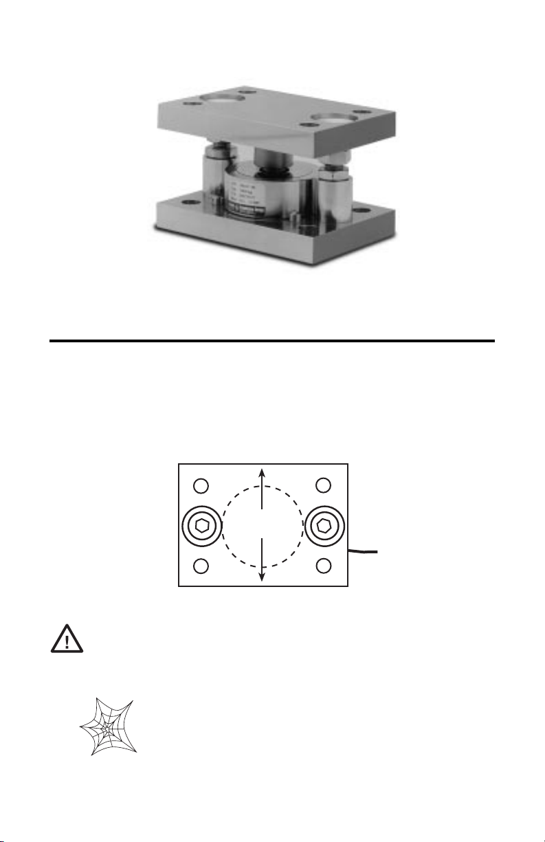
2.2 Installing the RLC
Top Plate
Upper Bearing
Rocker Pin
Lower Bearing
Grounding Cable
Load Cell
Base Plate
The RLC self aligning mount should be installed without the load cell or dummy
being present, while observing the following guidelines:
1. Assemble the self aligning mount as shown in the assembly drawing,
taking care that the top and base plates are correctly aligned (the RLC does
not lie in the center of the base plate and so care should be taken to ensure
that the upper bearing locating hole is correctly aligned).
2. The top plate (3) should be locked at Dimension A, as shown on the
dimensional outline drawing, using the M12x60 or M16x70 socket head
screws (12) and the M12 or M16 nuts (10).
3
Page 6

3. The M12x60 or M16x70 socket head screws (12) should be locked
securely by turning the thin M12 or M16 nuts (11) downwards to the
baseplate (4).
4. Locate the self aligning mount and secure it by using the four upper and
lower fixing holes.
5. Coat lower bearing (1) load surface with high pressure grease and insert
into RLC load cell.
6. Remove the M8x20 hex socket screw (7). Coat upper bearing (2) load
surface with high pressure grease, and slide assembly into place, ensuring
that upper bearing (2) and rocker pin (6) are properly located.
7. Replace screw (7) to contain RLC load cell assembly.
8. Rotate M12 or M16 nuts (10) counter clockwise by 1/2 turn at a time until
the load is taken by the RLC.
Warning: For safety reasons, always use a tool to align the upper bearing (2) if
necessary during this process.
9. A correctly installed mount should result in a height of 75mm or 100mm
for the low and high capacities respectively. Verify a free horizontal
movement of 3mm.
Use extreme care when lowering the vessel. The
Caution
force of a vessel weighing several tons can damage a
load cell if dropped only a fraction of an inch.
3. Load Cell Wiring
1. Route the load cell cables so they will not be damaged or cut. Cable should
not be routed near heat sources greater than 150 °F. Do not shorten any
load cell cable. The load cell is temperature compensated with the supplied
length of cable. Cutting the cable will affect temperature compensation.
Coil and protect excess cable so it will not be mechanically damaged or be
sitting in water.
4
Page 7

2. Provide a drip loop in all cables so that water or other liquids will not run
a
a
a
a
a
a
a
aa
a
aa
aaa
a
a
a
a
a
a
a
aa
a
a
aa
a
a
a
a
a
aa
a
a
a
a
a
a
aa
a
a
a
a
a
a
a
a
a
a
a
a
a
a
a
aa
a
a
a
a
a
a
a
a
a
a
a
a
a
a
a
a
a
a
a
a
a
a
a
a
a
a
aa
a
a
directly down the cables onto either the load cells or the junction box.
Attach load cell cable to the dead structure, not the vessel.
3. If conduit protection is necessary against mechanical or rodent damage to
the load cell cables, use flexible conduit and conduit adapters at the load
cells.
4. Connect cables to the summing board in the junction box according to the
guide shown below and the labels on the terminal strips of the junction box.
To verify the wiring scheme, see the certification shipped with each load
cell.
5. For better performance, use positive and negative remote sense lines if the
wiring running from the juction box to the indicator is longer than 25 feet.
Drip Loop
lleCdaoL noitcnuF
kniPCXE+
yerGCXE–
nworBGIS+
etihWGIS–
eraBDLEIHS
4. Junction Box Connections, Adjustments & Calibration
1. Refer to the Junction Box manual for trimming details.
2. Refer to the indicator manual for system calibration details.
5
Page 8

5. Troubleshooting
If the system powers up and gives some type of stable digital readout that varies with
the load on the system, any system problems are probably caused by factors other
than the load cells. The load cells are often blamed for a malfunctioning system, but
90% of the time, the problem lies elsewhere. Look for mechanical causes for your
problem first.
If the system can be calibrated but doesn’t return to zero, loses calibration, or
demonstrates non-linearity or non-repeatability, see the following chart for possible
causes and do the following checks.
Symptom
No return to zero
Non-linearity
Non-repeatability
Lost calibration Out of level or plumb; moisture problem; mechanical binding
Drifting readout Moisture in junction box, cables, or load cell; mechanical binding
Possible Cause
Mechanical binding or debris in seals or under load cells; may have lost system
calibration
Thermal expansion or deflection under load causing binding or side load
Loose load cell mount; drifting caused by moisture, load cell overload or shock
damage; mechanical binding
1. Check weigh module for debris restricting load cell movement or
debris between scale and structure.
2. Check that tank/vessel and modules are plumb, level and square at the
critical areas.
3. Check all piping and conduit for connections which restrict vessel
movement.
4. If check rods are used, loosen all connections to finger tight only for
testing.
5. Check load cell cables for physical or water damage.
6. Check all electrical connections, especially in the junction box.
If the problem still is not found:
7. Check possible indicator malfunction by using a load cell simulator to
input a known good signal into the indicator.
8. Disconnect each load cell’s signal leads at the junction box and check
individual load cell outputs with a multimeter. Then check input/
output impedances for comparison with load cell manufacturer’s
specifications.
If after all these checks the problem still cannot be isolated, reconnect all but one
load cell. Replace the load cell with a load cell simulator. Alternate so that each cell
is individually disconnected and replaced with a simulator. If there is a problem
with a particular load cell, the symptom should disappear when that load cell is
disconnected and replaced with the simulator.
6
Page 9

6. Maintenance and Replacement Parts
12
3
2
9
6
10
1
11
7
5
5
4
2b
6b
8
HIGH CAPACITY SILO MOUNT
5
5
metI
rebmuN
noitpircseD rebmuNtraP
1gniraeBrewoLyrotcaftlusnoC
2gniraeBreppU
3etalPpoT
4etalPesaB
5esaerGerusserPhgiH
6niPrekcoR
7)02x8M2ASS(xeH,tekcoS,wercSteS
8elbaCgnidnuorG
9)21M2ASS(rehsaW
01)21M2ASS(xeH,tuN
11)21M2ASS(xeHnihT,tuN
21)21M2ASS(xeH,knuSretnuoC,wercS
7
Page 10

7. RLC Limited Warranty
Rice Lake Weighing Systems (RLWS) warrants that all RLWS equipment and systems
properly installed by a Distributor or Original Equipment Manufacturer (OEM) will operate
per written specifications as confirmed by the Distributor/OEM and accepted by RLWS. All
weigh modules are warranted against defects in materials and workmanship for two (2) years.
RLWS warrants that the equipment sold hereunder will conform to the current written
specifications authorized by RLWS. RLWS warrants the equipment against faulty workmanship and defective materials. If any equipment fails to conform to these warranties, RLWS
will, at its option, repair or replace such goods returned within the warranty period subject
to the following conditions:
Upon discovery by Buyer of such nonconformity, RLWS will be given prompt written
•
notice with a detailed explanation of the alleged deficiencies.
• Individual electronic components returned to RLWS for warranty purposes must be
packaged to prevent electrostatic discharge (ESD) damage in shipment. Packaging
requirements are listed in a publication, “Protecting Your Components From Static
Damage in Shipment,” available from RLWS Equipment Return Department.
• Examination of such equipment by RLWS confirms that the nonconformity actually
exists, and was not caused by accident, misuse, neglect, alteration, improper installation, improper repair or improper testing; RLWS shall be the sole judge of all alleged
non-conformities.
• Such equipment has not been modified, altered, or changed by any person other than
RLWS or its duly authorized repair agents.
• RLWS will have a reasonable time to repair or replace the defective equipment. Buyer
is responsible for shipping charges both ways.
• In no event will RLWS be responsible for travel time or on-location repairs, including
assembly or disassembly of equipment, nor will RLWS be liable for the cost of any
repairs made by others.
THESE WARRANTIES EXCLUDE ALL OTHER WARRANTIES, EXPRESSED OR
IMPLIED, INCLUDING WITHOUT LIMITATION WARRANTIES OF MERCHANTABILITY OR FITNESS FOR A PARTICULAR PURPOSE. NEITHER RLWS NOR
DISTRIBUTOR WILL, IN ANY EVENT, BE LIABLE FOR INCIDENTAL OR CONSEQUENTIAL DAMAGES.
RLWS AND BUYER AGREE THAT RLWS’S SOLE AND EXCLUSIVE LIABILITY
HEREUNDER IS LIMITED TO REPAIR OR REPLACEMENT OF SUCH GOODS. IN
ACCEPTING THIS WARRANTY, THE BUYER WAIVES ANY AND ALL OTHER
CLAIMS TO WARRANTY.
SHOULD THE SELLER BE OTHER THAN RLWS, THE BUYER AGREES TO LOOK
ONLY TO THE SELLER FOR WARRANTY CLAIMS.
No terms, conditions, understanding, or agreements purporting to modify the terms of this
warranty shall have any legal effect unless made in writing and signed by a corporate officer
of RLWS and the Buyer.
© 1999 Rice Lake Weighing Systems, Inc. Rice Lake, WI USA. All Rights Reserved.
RICE LAKE WEIGHING SYSTEMS • 230 WEST COLEMAN STREET
RICE LAKE, WISCONSIN 54868 • USA
8
 Loading...