

Page 1
RL50210 TA/65059
Load Cell Mounting Kit
Installation
Guide
25713
1
Page 2

Contents
1. Introduction ............................................................................. 1
2. Mechanical Installation........................................................... 2
2.1 Installation Guidelines for Compression Weighing Assemblies...2
2.2 Installing the RL50210 TA/65059 Mount .....................................3
3. Load Cell Wiring...................................................................... 6
4. Junction Box Connections, Adjustments & Calibration...... 6
5. Troubleshooting...................................................................... 7
6. Maintenance and Replacement Parts.................................... 8
7. Limited Warranty................................................................... 11
© 2004 Rice Lake Weighing Systems. All rights reserved.
Printed in the United States of America.
Specifications subject to change without notice.
2
01/04
Page 3
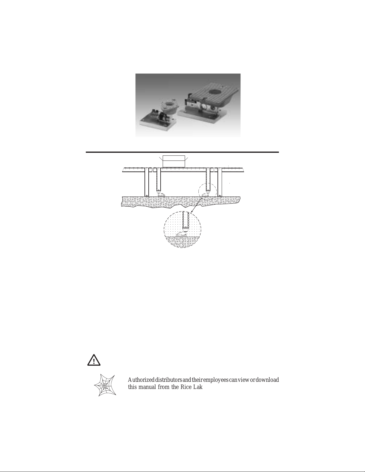
1. Introduction
Typical Mounting Configuration
Rice Lake Weighing Systems’ 50210 TA/65059 Mini-Tank Weighing Assemblies
provide an easy-to-use, cost-effective, and reliable method for low capacity
weighing applications. They are ideal for installations where checking requirements are low. The flexible neoprene mounting system allows for bolting the units
directly to the mounting surface without extra plates or load buttons. The neoprene
pad also allows the vessel to expand/contract without restriction and provides a
degree of shock protection.
The 50210TA/65059 Mini-Tank Weighing Assemblies are available from 50-250
lb. capacities in zinc-plated or stainless steel versions using cantilever beam load
cells. In capacities from 500-2,500 lb., the units use single-ended shear-beam load
cells and are available in zinc-plated steel or stainless steel. 1K-2.5K capacities can
be fitted with RL35083 or RL35082 stainless steel, welded seal, IP67 load cell. This
is a non-part numbered special. Consult factory for quote information.
Caution
The installation should be planned by a qualified structural
engineer. Each installation is unique, and this manual is meant
to serve only as a general guideline for installation.
Authorized distributors and their employees can view or download
this manual from the Rice Lake Weighing Systems distributor
site at www.rlws.com.
1
3
Page 4

2. Mechanical Installation
2.1 Installation Guidelines for Compression Weighing Assemblies
1. The mounting surface for the base plate and top plate must be level. After
installation, the top and bottom plates must be level within ±0.5°. If the
mounting surfaces are not level, then shims and/or grout may be used to
level the mount.
If possible, check that the mount is level when the vessel is fully loaded
because excessive deflections in legs and supporting structures may cause
additional side forces which greatly affect accuracy. Deflection of the
mount’s top or base plate due to loading should not exceed ±0.5°.
Reinforcement of legs or support structure may be necessary to correct this.
Vessels with long legs should have cross bracing applied between adjacent
legs to keep them from spreading under loads.
2. Compression mounting systems use three, four, or more mounts. More than
eight mount systems should be avoided as even weight distribution becomes
extremely difficult to achieve. The load on each mount assembly should vary
no more than 20%. Add shims where necessary to achieve correct load
distribution.
3. If the actual load cells are used during installation, extreme care must be
taken to prevent overload damage. A tank or hopper weighing several tons
can exert huge forces when dropped only a fraction of an inch. Dummy
load cells can be used during installation.
4. The neoprene mount of the RL50210 TA/65059 compresses as load is
applied, making the mount particularly suitable for applications involving
minor shock loading. However, it is not recommended for vessels with
attached piping because the added downward deflection of the vessel as it is
loaded makes it difficult to design a piping system with the required degree
of flexibility.
5. Load cells should not be installed in the mounts until all welding is
completed. The heat generated by welding current passing through a load
cell can damage the adhesive holding the strain gauge to the body. If
possible, use a dummy load cell when welding to maintain finished height.
If welding is unavoidable after load cell installation, connect the ground in
such a way that the current does not flow through the load cell. For
example, if welding on the mount top plate, the ground must be connected
to the vessel, not to the mount base or support structure. Also, protect the
load cell and cable from weld splatter.
Note: The arrow on the load cell should point in the direction of the load.
2
4
Page 5

6. Use only “hermetically sealed” load cells in washdown applications.
“Environmentally protected” load cells are not suitable for such applications and will be damaged. If tanks and surrounding equipment are
frequently steam cleaned, or if the load cell is subjected to direct washdown,
a protective shroud for the weighing assembly is recommended. Proper
drainage is nescessary so the weighing assembly is not standing in water.
7. All support points should be equally stiff so that they deflect by the same
amount as the vessel is loaded.
2.2 Installing the RL50210 TA/65059 Mount
The RL50210 TA/65059 load cell mount installation instructions are presented in
the following paragraphs. Shown in the figure below are typical load cell mount
installations for the 50-250 and 500 lb. configurations.
50-250 lb
NEOPRENE MOUNT
500 lb
LOADING SPACER
SOCKET HEAD
CAP SCREW
TYPE B
PLAIN WASHER
LOADING SPACER
FLEX LOCK NUT
BASE PLATE
SOCKET HEAD
CAP SCREW
NEOPRENE
MOUNT
FLAT WASHER
MACHINE SCREW
OVERLOAD STOP
SOCKET HEAD
SET SCREW
NYLON PLUG
PLAIN WASHER
BASE PLATE
LOCK WASHER
TOP PLATE
TOP PLATE
SOCKET HEAD
LOAD CELL SCREWS
LOCK WASHER
DEFLECTION
SPACER
CANTILEVER BEAM LOAD CELL
SOCKET HEAD
LOAD CELL SCREWS
LOCK
WASHER
FLAT
WASHER
DEFLECTION
SPACER
SHEAR BEAM LOAD CELL
5
3
Page 6

The type of installation, vessel support structure, and the surface upon which the
mount is to be placed determines the method of locating, attaching, and assembling
the RL50210TA/65059 Mounting Assembly. Carefully consider the following
three areas that commonly cause accuracy problems:
• Are the supporting legs adequately braced so they will not spread when the
system is fully loaded?
• Does the supporting structure have the necessary strength to prevent
excessive deflection when the system is fully loaded?
• Is there attached equipment such as skirting, venting, or piping which is
likely to cause binding or lack of flexibility?
After considering any areas that may cause accuracy problems, follow these installation steps.
1. Determine where to position the mount and in which direction it should be
oriented. The preferred mounting orientation for single ended beams is with
the longitudinal axis of the load cell pointing toward the center of the vessel
in circular mounting configurations as illustrated in Figures 1 and 2.
Figures 3 and 4 illustrate mounting configurations for square and rectangular
vessels. For rectangular vessels, the load cell’s longitudinal axis should be
aligned along the vessel’s longest dimension as shown in Figure 4. In any
application where a recurring side force is present in one direction, such as in
a conveyor belt or roller platform, the longitudinal axis of the load cell should
align with that force.
Figure 1
Figure 2
Figure 3
Figure 4
2. Lift and block the vessel to the same height as the assembled mounts.
3. Remove the block from one support point and slide a mount into position.
4. If the mount is being fitted under the leg of a vessel, verify that the center line
of the leg passes through the center of the neoprene mount (through the center
of the load cell’s load hole).
5. Attach the top plate of the neoprene mount by bolting. Do not fully tighten as
shimming may be necessary to level.
6
4
Page 7

6. Repeat Steps 4, 5, and 6 for the remaining mounts. The vessel should now be
supported on the mounts alone.
7. If necessary, move the vessel to its final position. Verify that there is no initial
misalignment between the base plate and top plate by lifting the vessel
slightly at each support point in turn. This will also indicate if the load is
evenly distributed on all mounts. Shim if necessary.
8. Attach the base plates to the foundation using anchors for concrete or by
bolting or welding to a steel structure. Verify that the base plates are no more
than ±0.5° out of level. Shim as necessary.
9. Check that the top plates are no more than ±0.5° out of level. Shim if necessary
and fully tighten the bolts.
10. The load distribution can be checked more accurately by exciting each load
cell and measuring the output with a voltmeter. The variation in load among
the cells should be no more than 20%. Shim if necessary.
11. Check that the two screws securing the load cell to the base plate are tight. The
torque values are listed in the following table.
)bl(yticapaClleCdaoL )bl-tf(euqroTdednemmoceR
052–0521
0052–00507
7
5
Page 8

3. Load Cell Wiring
1. Route the load cell cables so they will not be damaged or cut. Cable should
not be routed near heat sources greater than 150 °F. Do not shorten any
load cell cable. The load cell is temperature compensated with the
supplied length of cable. Cutting the cable will affect temperature compensation. Coil excess cable and protect it so it will not be mechanically
damaged or be sitting in water.
2. Provide a drip loop in all cables so that water or other liquids will not run
directly down the cables onto either the load cells or the junction box.
Attach load cell cable to the dead structure, not the vessel.
3. If conduit protection is necessary against mechanical or rodent damage to
the load cell cables, use flexible conduit and conduit adapters at the load
cells.
4. Connect cables for RL50210, RL30000, RL50210SS, RL35023S, 60040,
65023, and 65023S load cells to the summing board in the junction box
according to the guide shown below and the labels on the terminal strips
of the junction box. To verify the wiring scheme, see the certification
shipped with the load cell.
5. For better performance, use positive and negative remote sense lines if the
wiring run from the junction box to the indicator is longer than 25 feet.
DRIP
LOOP
ROLOCERIWLLECDAOL NOITCNUF
deRCXE+
kcalBCXE–
neerGGIS+
etihWGIS–
eraBroyarGDLEIHS
4. Junction Box Connections, Adjustments & Calibration
• Refer to junction box manual for trimming details.
• Refer to the indicator manual for system calibration guidelines.
6
8
Page 9

5. Troubleshooting
If the system powers up and gives some type of stable digital readout that varies with
the load on the system, the system problems are probably caused by factors other
than the load cells. All too often, the load cells are blamed for a malfunctioning
system; 90% of the time, the problem lies elsewhere. Look for mechanical causes
for your problem first.
If the system can be calibrated but doesn’t return to zero, loses calibration, or
demonstrates non-linearity or non-repeatability, see the following chart for possible
causes and refer to the following list of checks.
Symptom
No return to zero
Non-linearity
Non-repeatability
Lost calibration Out of level or plumb; moisture problem; mechanical binding
Drifting readout Moisture in junction box, cables, or load cell; mechanical binding
Possible Cause
Mechanical binding or debris in seals or under load cells; may have lost system
calibration
Thermal expansion or deflection under load causing binding or side load
Loose load cell mount; drifting caused by moisture, load cell overload or shock
damage; mechanical binding
1. Check load cell mount for debris restricting load cell movement or debris
between scale and structure. Check any overload stops for proper clearance.
2. Check that tank/vessel and mounts are plumb, level, and square at the critical
areas.
3. Check all piping and conduit for connections which restrict vessel movement.
4. If check rods are used, loosen all connections to finger tight only for testing.
5. Check load cell cables for physical or water damage.
6. Check all electrical connections, especially in the junction box.
If the problem still is not found:
7. Check possible indicator malfunction by using a load cell simulator to input
a known good signal into the indicator.
8. Disconnect each load cell’s signal leads at the junction box and check
individual load cell outputs with a multimeter. Then check input/output
impedances for comparison with load cell manufacturer’s specifications.
If after all these checks the problem still cannot be isolated, reconnect all but one
load cell. Replace the load cell with a load cell simulator. Alternate so that each load
cell is individually disconnected and replaced with a simulator. If there is a problem
with a particular load cell, the symptom should disappear when that load cell is
disconnected and replaced with the simulator.
9
7
Page 10

6. Maintenance and Replacement Parts
2
1
11
10
9
8
3
4
5
6
7
MILD STEEL RL50210TA/65059 50-250 LB. CAPACITY
No. Description Qty. Replacement Part Numbers
50 lb. 100 lb. 150 lb. 250 lb.
1 .... Vibration Mount........................ 1.........18255... 18256 .... 18245 .... 18257
2 .... Socket Head Cap Screw.......... 1.........14983... 14983 .... 14983 .... 14983
3 .... Plain Washer............................ 1 .........21940... 21940 .... 21940 .... 21940
4 .... Socket Hd. Load Cell Screws .. 2 .........14982... 14982 .... 14982 .... 14982
5 .... 1/4" Lock Washer .................... 2 .........15147... 15147 .... 15147 .... 15147
6 .... Deflection Spacer..................... 1......... 18241... 18241 .... 18241 .... 18241
7 .... Cantilever Beam Load Cell ....... 1............ See Load Cell Guide
8 .... Base Plate ............................... 1.........18247... 18247 .... 18247 .... 18247
9 .... Flex Lock Nut........................... 1.........14643... 14643 .... 14643 .... 14643
10 .. Loading Spacer ....................... 1 .........18240... 18240 .... 18240 .... 18240
11 .. 1/4" Type B Plain Washer ........ 3......... 22011... 22011 .... 22011 .... 22011
STAINLESS STEEL RL50210TA/65059 50-250 LB. CAPACITY
No. Description Qty. Replacement Part Numbers
50 lb. 100 lb. 150 lb. 250 lb.
1 .... Vibration Mount........................ 1.........18255... 18256 .... 18245 .... 18257
2 .... Socket Head Cap Screw.......... 1.........63790... 63790 .... 63790 .... 63790
3 .... Plain Washer............................ 1 .........63791... 63791 .... 63791 .... 63791
4 .... Socket Hd. Load Cell Screws .. 2 .........63789... 63789 .... 63789 .... 63789
5 .... 1/4" Lock Washer .................... 2 .........15148... 15148 .... 15148 .... 15148
6 .... Deflection Spacer..................... 1......... 63794... 63794 .... 63794 .... 63794
7 .... Cantilever Beam Load Cell ....... 1............ See Load Cell Guide
8 .... Base Plate ............................... 1.........63795... 63795 .... 63795 .... 63795
9 .... Flex Lock Nut........................... 1.........63788... 63788 .... 63788 .... 63788
10 .. Loading Spacer ....................... 1 .........63793... 63793 .... 63793 .... 63793
11 .. 1/4" Type B Plain Washer ........ 3......... 63792... 63792 .... 63792 .... 63792
10
8
Page 11

2
1
13
12
11
10
3
4
5
13
6
9
8
7
MILD STEEL RL50210TA/65059 500 LB. CAPACITY
No. Description Qty. Replacement Part Numbers
RL50210 65059
1 ..... Vibration Mount......................... 1 ............. 18244 ......................... 18244
2 ..... Socket Head Cap Screw........... 1 ............. 32185 ......................... 32185
3 ..... Lock Washer ............................. 1 ............. 15167 ......................... 15167
4 ..... Socket Hd. Load Cell Bolts ....... 2 ............. 15069......................... 15069
5 ..... 1/2" Lock Washer ..................... 2 ............. 15167......................... 15167
6 ..... Deflection Spacer ...................... 1 ............. 17754 ......................... 18260
7 ..... Shear Beam Load Cell .............. 1 ............. See Load Cell Guide
8 ..... Base Plate................................. 1............. 18248......................... 18248
9 ..... Nylon Plug ................................ 1 ............. 18246......................... 18246
10 ... Socket Head Set Screw ............ 1 ............. 14949......................... 14949
11 ... Mach. Screw Overld. Stop ........ 1 ............. 14886......................... 14886
12 ... Loading Spacer......................... 1 ............. 18259......................... 18239
13 ... 1/2" Flat Washer ....................... 3 ............. 15173......................... 15173
STAINLESS STEEL RL50210TA/65059 500 LB. CAPACITY
No. Description Qty. Replacement Part Numbers
RL50210 65059
1 ..... Vibration Mount.......................... 1 ............. 18244 .......................... 18244
2 ..... Socket Head Cap Screw............ 1 ............. 32280 .......................... 32280
3 ..... Lock Washer .............................. 1 ............. 15168 .......................... 15168
4 ..... Socket Hd. Load Cell Bolts ........ 2 ............. 15065.......................... 15065
5 ..... 1/2" Lock Washer ...................... 2 ............. 15168.......................... 15168
6 ..... Deflection Spacer ....................... 1 ............. 18411 .......................... 18383
7 ..... Shear Beam Load Cell ............... 1 ............. See Load Cell Guide
8 ..... Base Plate.................................. 1 ............. 18382.......................... 18382
9 ..... Nylon Plug ................................. 1............. 18246 .......................... 18246
10 ... Socket Head Set Screw ............. 1 ............. 14950.......................... 14950
11 ... Mach. Screw Overld. Stop ......... 1 ............. 14887.......................... 14887
12 ... Loading Spacer.......................... 1 ............. 18410.......................... 18381
13 ... 1/2" Flat Washer ........................ 3 ............. 15170 .......................... 15170
11
9
Page 12

1
12
3
11
10
9
8
2
4
1
5
6
7
MILD STEEL RL50210TA/65059 1,000 LB. - 2,500 LB. CAPACITY
No. Description Qty. Replacement Part Numbers
1,000 lb. 2,000 lb. 2,500 lb.
1 ..... 1/2" Flat Washer ................... 3 ............ 15173 ........... 15173......... 15173
2 ..... Socket Head Cap Screw....... 2 ............ 15076 ........... 15076 ......... 15076
3 ..... Neoprene Mount ...................1 ............ 18258 ........... 26819......... 26819
4 ..... 1/2" Lock Washer ................. 3 ............ 15167 ........... 15167 ......... 15167
5 ..... Shear Beam Load Cell .......... 1 ............ See Load Cell Guide
6 ..... Deflection Spacer .................. 1 ............ 18260 ........... 18260 ......... 18260
7 ..... Base Plate............................. 1 ............ 18248 ........... 18248 ......... 18248
8 ..... Nylon Plug ............................ 1 ............ 18246 ........... 18246 ......... 18246
9 ..... Socket Head Set Screw ........1 ............ 14949 ........... 14949......... 14949
10 ... Mach. Screw Overld. Stop .... 1 ............ 14886 ........... 14886 ......... 14886
11 ... Loading Spacer..................... 1 ............ 18239 ........... 18239......... 18239
12 ... Socket Head Cap Screw....... 1 ............ 15076 ........... 15069 ......... 15069
STAINLESS STEEL RL50210TA/65059 1,000 LB. - 2,500 LB. CAPACITY
No. Description Qty. Replacement Part Numbers
1,000 lb. 2,000 lb. 2,500 lb.
1 ..... 1/2" Flat Washer ................... 3 ............ 15170 ........... 15170......... 15170
2 ..... Socket Head Cap Screw....... 2 ............ 15077 ........... 15077 ......... 15077
3 ..... Neoprene Mount ...................1 ............ 18258 ........... 26819......... 26819
4 ..... 1/2" Lock Washer ................. 3 ............ 15168 ........... 15168 ......... 15168
5 ..... Shear Beam Load Cell .......... 1 ............ See Load Cell Guide
6 ..... Deflection Spacer .................. 1 ............ 18383 ........... 18383 ......... 18383
7 ..... Base Plate............................. 1 ............ 18382 ........... 18382 ......... 18382
8 ..... Nylon Plug ............................ 1 ............ 18246 ........... 18246 ......... 18246
9 ..... Socket Head Set Screw ........1 ............ 14950 ........... 14950......... 14950
10 ... Mach. Screw Overld. Stop .... 1 ............ 14887 ........... 14887 ......... 14887
11 ... Loading Spacer..................... 1 ............ 18381 ........... 18381......... 18381
12. .. Socket Head Cap Screw....... 1 ............ 15077 ........... 15065 ......... 15065
10
Page 13

7. Limited Warranty
Rice Lake Weighing Systems (RLWS) warrants that all RLWS equipment and systems
properly installed by a Distributor or Original Equipment Manufacturer (OEM) will operate
per written specifications as confirmed by the Distributor/OEM and accepted by RLWS. All
weigh modules are warranted against defects in materials and workmanship for two (2) years.
RLWS warrants that the equipment sold hereunder will conform to the current written
specifications authorized by RLWS. RLWS warrants the equipment against faulty workmanship and defective materials. If any equipment fails to conform to these warranties, RLWS
will, at its option, repair or replace such goods returned within the warranty period subject to
the following conditions:
• Upon discovery by Buyer of such non-conformity, RLWS will be given prompt written
notice with a detailed explanation of the alleged deficiencies.
•Individual electronic components returned to RLWS for warranty purposes must be
packaged to prevent electrostatic discharge (ESD) damage in shipment. Packaging
requirements are listed in a publication, “Protecting Your Components From Static
Damage in Shipment,” available from RLWS Equipment Return Department.
•Examination of such equipment by RLWS confirms that the non-conformity actually
exists, and was not caused by accident, misuse, neglect, alteration, improper installation, improper repair or improper testing; RLWS shall be the sole judge of all alleged
non-conformities.
• Such equipment has not been modified, altered, or changed by any person other than
RLWS or its duly authorized repair agents.
• RLWS will have a reasonable time to repair or replace the defective equipment. Buyer
is responsible for shipping charges both ways.
•In no event will RLWS be responsible for travel time or on-location repairs, including
assembly or disassembly of equipment, nor will RLWS be liable for the cost of any
repairs made by others.
THESE WARRANTIES EXCLUDE ALL OTHER WARRANTIES, EXPRESSED OR
IMPLIED, INCLUDING WITHOUT LIMITATION WARRANTIES OF MERCHANTABILITY OR FITNESS FOR A PARTICULAR PURPOSE. NEITHER RLWS NOR DISTRIBUTOR WILL, IN ANY EVENT, BE LIABLE FOR INCIDENTAL OR CONSEQUENTIAL DAMAGES.
RLWS AND BUYER AGREE THAT RLWS’S SOLE AND EXCLUSIVE LIABILITY
HEREUNDER IS LIMITED TO REPAIR OR REPLACEMENT OF SUCH GOODS. IN
ACCEPTING THIS WARRANTY, THE BUYER WAIVES ANY AND ALL OTHER
CLAIMS TO WARRANTY.
SHOULD THE SELLER BE OTHER THAN RLWS, THE BUYER AGREES TO LOOK
ONLY TO THE SELLER FOR WARRANTY CLAIMS.
No terms, conditions, understanding, or agreements purporting to modify the terms of this
warranty shall have any legal effect unless made in writing and signed by a corporate officer
of RLWS and the Buyer.
© 2004 Rice Lake Weighing Systems, Inc. Rice Lake, WI USA. All Rights Reserved.
RICE LAKE WEIGHING SYSTEMS • 230 WEST COLEMAN STREET
RICE LAKE, WISCONSIN 54868 • USA
11
 Loading...