

Page 1
RL-22DT/RL-42DT
Thermal Printer
Version 3.007
Operation Manual
108222
Page 2

Page 3

Contents
5FDIOJDBMUSBJOJOHTFNJOBSTBSFBWBJMBCMFUISPVHI3JDF-BLF8FJHIJOH4ZTUFNT
$PVSTFEFTDSJQUJPOTBOEEBUFTDBOCFWJFXFEBUXXXSJDFMBLFDPNPSPCUBJOFECZ
DBMMJOHBOEBTLJOHGPSUIFUSBJOJOHEFQBSUNFOU
About This Manual ................................................................................................................................... 1
1.0 Introduction.................................................................................................................................. 1
1.1 Safety Instructions . . . . . . . . . . . . . . . . . . . . . . . . . . . . . . . . . . . . . . . . . . . . . . . . . . . . . . . . . . . . . . . 1
1.2 Printer Parts . . . . . . . . . . . . . . . . . . . . . . . . . . . . . . . . . . . . . . . . . . . . . . . . . . . . . . . . . . . . . . . . . . . . 1
2.0 Installation ................................................................................................................................... 4
2.1 Label Installation. . . . . . . . . . . . . . . . . . . . . . . . . . . . . . . . . . . . . . . . . . . . . . . . . . . . . . . . . . . . . . . . . 4
2.2 Label Roll Core Switch . . . . . . . . . . . . . . . . . . . . . . . . . . . . . . . . . . . . . . . . . . . . . . . . . . . . . . . . . . . . 7
2.3 PC Connection. . . . . . . . . . . . . . . . . . . . . . . . . . . . . . . . . . . . . . . . . . . . . . . . . . . . . . . . . . . . . . . . . . 8
2.3.1 Store Format - Autoform Capability . . . . . . . . . . . . . . . . . . . . . . . . . . . . . . . . . . . . . . . . . . . . . . . . . . . . 8
2.3.2 Deleting the AUTOFR Form From the Printer . . . . . . . . . . . . . . . . . . . . . . . . . . . . . . . . . . . . . . . . . . . . . 8
3.0 Accessories ................................................................................................................................. 9
3.1 Stripper Module . . . . . . . . . . . . . . . . . . . . . . . . . . . . . . . . . . . . . . . . . . . . . . . . . . . . . . . . . . . . . . . . . 9
3.2 Cutter Installation . . . . . . . . . . . . . . . . . . . . . . . . . . . . . . . . . . . . . . . . . . . . . . . . . . . . . . . . . . . . . . . 13
4.0 Control Panel ............................................................................................................................. 16
4.1 LED Status. . . . . . . . . . . . . . . . . . . . . . . . . . . . . . . . . . . . . . . . . . . . . . . . . . . . . . . . . . . . . . . . . . . . 16
4.2 Feed Key Introduction . . . . . . . . . . . . . . . . . . . . . . . . . . . . . . . . . . . . . . . . . . . . . . . . . . . . . . . . . . . 16
4.3 Self-Test. . . . . . . . . . . . . . . . . . . . . . . . . . . . . . . . . . . . . . . . . . . . . . . . . . . . . . . . . . . . . . . . . . . . . . 17
4.4 Auto-Sensing . . . . . . . . . . . . . . . . . . . . . . . . . . . . . . . . . . . . . . . . . . . . . . . . . . . . . . . . . . . . . . . . . . 17
4.5 Dump Mode . . . . . . . . . . . . . . . . . . . . . . . . . . . . . . . . . . . . . . . . . . . . . . . . . . . . . . . . . . . . . . . . . . . 18
4.6 See-Through Sensor On/Off . . . . . . . . . . . . . . . . . . . . . . . . . . . . . . . . . . . . . . . . . . . . . . . . . . . . . . . 18
4.7 Error Messages . . . . . . . . . . . . . . . . . . . . . . . . . . . . . . . . . . . . . . . . . . . . . . . . . . . . . . . . . . . . . . . . 18
5.0 Maintenance and Adjustments.................................................................................................. 19
5.1 Print Head module Installation/Removal . . . . . . . . . . . . . . . . . . . . . . . . . . . . . . . . . . . . . . . . . . . . . . 19
5.2 Thermal Print Head Cleaning . . . . . . . . . . . . . . . . . . . . . . . . . . . . . . . . . . . . . . . . . . . . . . . . . . . . . . 21
5.3 Cutter Adjustment (Paper Jams) . . . . . . . . . . . . . . . . . . . . . . . . . . . . . . . . . . . . . . . . . . . . . . . . . . . . 21
6.0 Appendix .................................................................................................................................... 22
6.1 Control Commands . . . . . . . . . . . . . . . . . . . . . . . . . . . . . . . . . . . . . . . . . . . . . . . . . . . . . . . . . . . . . 22
6.2 Specifications . . . . . . . . . . . . . . . . . . . . . . . . . . . . . . . . . . . . . . . . . . . . . . . . . . . . . . . . . . . . . . . . . . 23
6.3 Compliance Statements . . . . . . . . . . . . . . . . . . . . . . . . . . . . . . . . . . . . . . . . . . . . . . . . . . . . . . . . . . 24
6.4 Serial Interface . . . . . . . . . . . . . . . . . . . . . . . . . . . . . . . . . . . . . . . . . . . . . . . . . . . . . . . . . . . . . . . . . 25
6.5 USB Interface . . . . . . . . . . . . . . . . . . . . . . . . . . . . . . . . . . . . . . . . . . . . . . . . . . . . . . . . . . . . . . . . . . 25
6.6 Internal Interface. . . . . . . . . . . . . . . . . . . . . . . . . . . . . . . . . . . . . . . . . . . . . . . . . . . . . . . . . . . . . . . . 25
6.7 Troubleshooting . . . . . . . . . . . . . . . . . . . . . . . . . . . . . . . . . . . . . . . . . . . . . . . . . . . . . . . . . . . . . . . 25
RL-22DT/42-DT Limited Warranty........................................................................................................... 26
© 2011 Rice Lake Weighing Systems. All rights reserved. Printed in the United States of America.
Specifications subject to change without notice.
February 2011
i
Page 4

ii RL-22DT/RL-42DT Operation Manual
Page 5
About This Manual
Warning
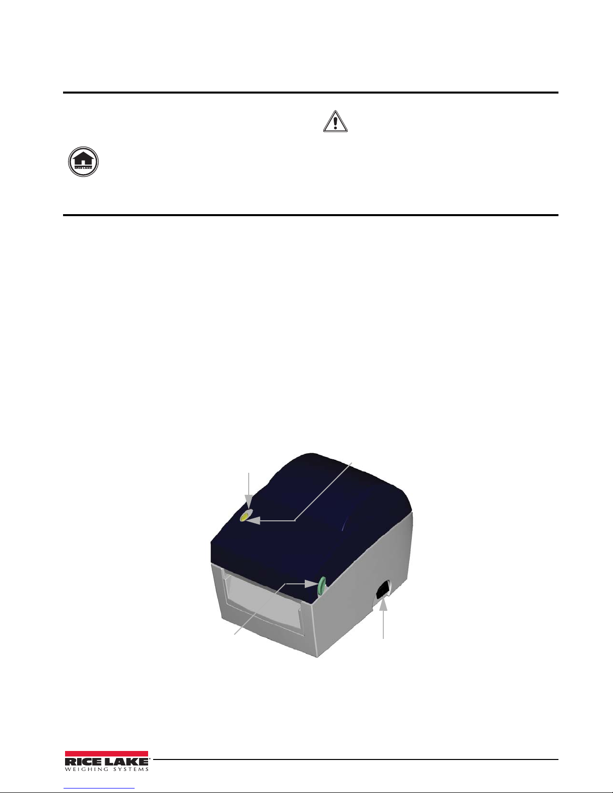
LED Light
Feed key
Power Switch
Cover Option
button
This manual is intended for use by qualified service
technicians responsible for installing and servicing the
RL-22DT/RL-42DT printers.
Authorized distributors and their employees
Danger of explosion if battery is incorrectly
replaced. Replace only with the equivalent
type recommended by the manufacturer.
Dispose of batteries according to the
manufacturer’s instructions.
can view or download this manual from the
Rice Lake Weighing Systems distributor
www.ricelake.com.
site at
1.0 Introduction
After unpacking, check to make sure all accessories are included:
• Barcode printer
• Power cord
• Switching power
1.1 Safety Instructions
• Keep the equipment away from humidity.
• Before you connect the equipment to the power outlet, check the voltage of the power source.
• Disconnect the equipment from the voltage of the power source to prevent possible transient
over-voltage damage.
• Don’t pour any liquid near the equipment, as it may result in electric shock.
• Only qualified service personnel should open the equipment.
• Don’t repair or adjust energized equipment alone under any circumstances. Someone capable of
providing first aid must always be present for your safety.
•USB cable
• Label
1.2 Printer Parts
Figure 1-1. Outside of printer
RL-22DT/42DT Operation Manual - Introduction 1
Page 6
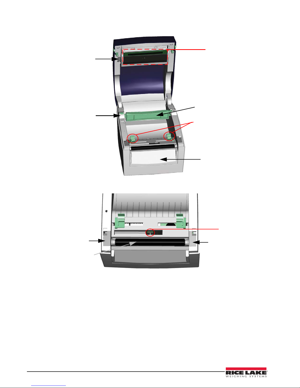
Print Head Lift
Label Roll Holder
Print Mechanism
Label Roll Core
Label Guides
Front Cover Piece
Platen Cover
Platen Cover
Label Sensor
Label Roller
Figure 1-2. Inside of printer
Figure 1-3. Inside of printer
2 RL-22DT/42DT Operation Manual
Page 7
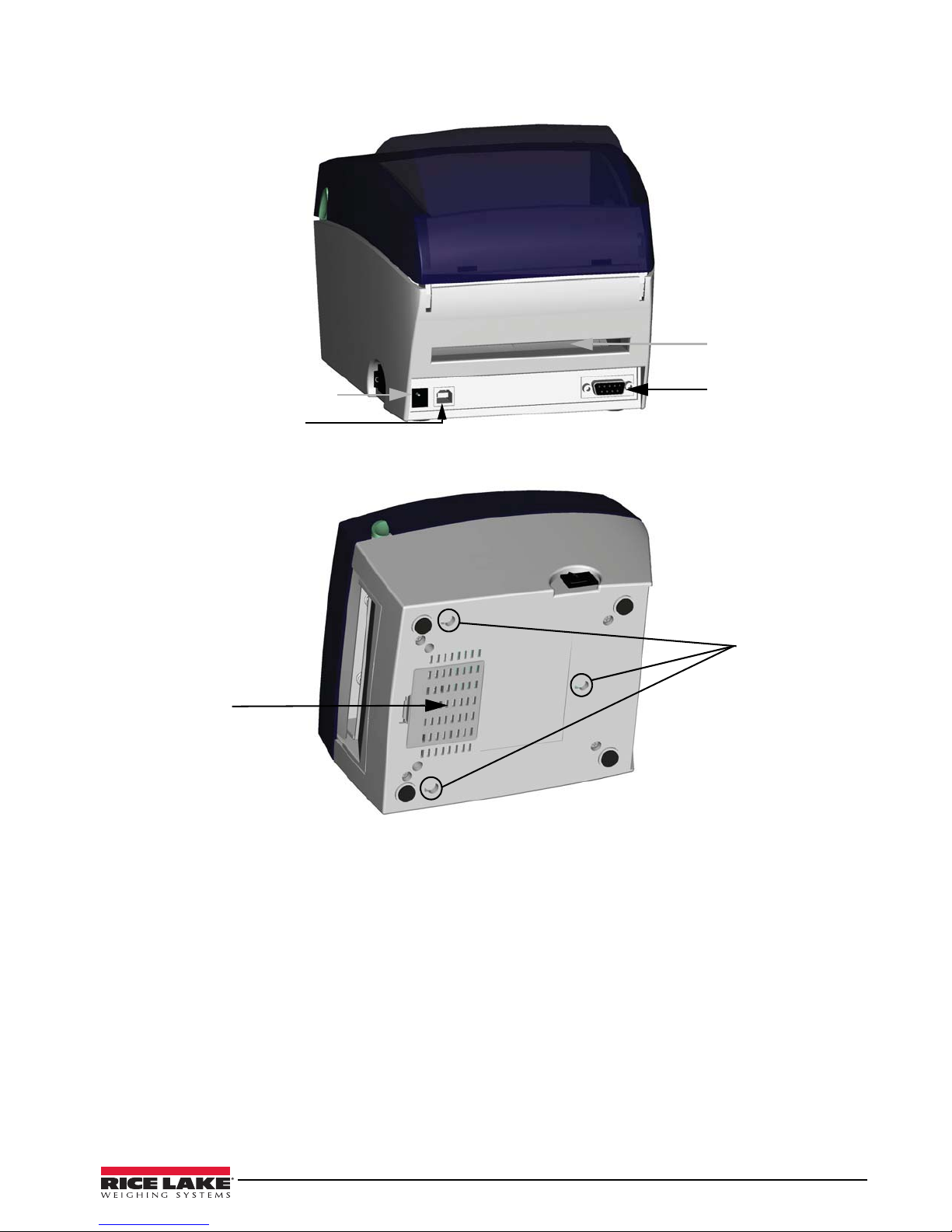
Figure 1-4. Back of printer
Power Socket
USB Port
Fan-Fold Label Insert
Serial Port (RS-232)
Bottom Case Cover
Hang Holes
Figure 1-5. Bottom of printer
RL-22DT/42DT Operation Manual - Introduction 3
Page 8
2.0 Installation
This section contains instructions on installing labels, the label roll core switch, and software and driver
installation.
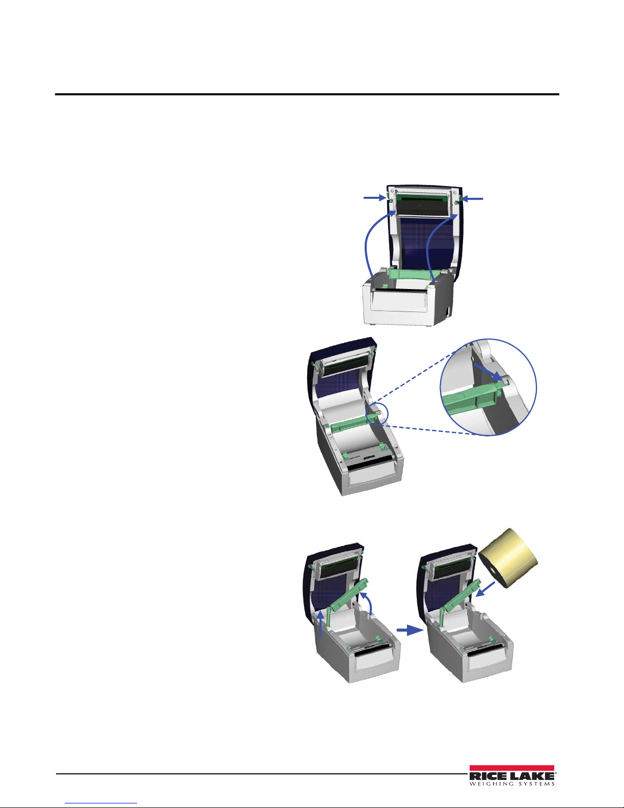
2.1 Label Installation
1. Place the printer on a horizontal surface
and open the top cover.
2. Press and release the lock of the label roll
core.
3. Pull up the label roll holder and lift the
label roll core upward.
4. Place a new label roll onto the label roll
core.
4 RL-22DT/RL-42DT Operation Manual
Page 9
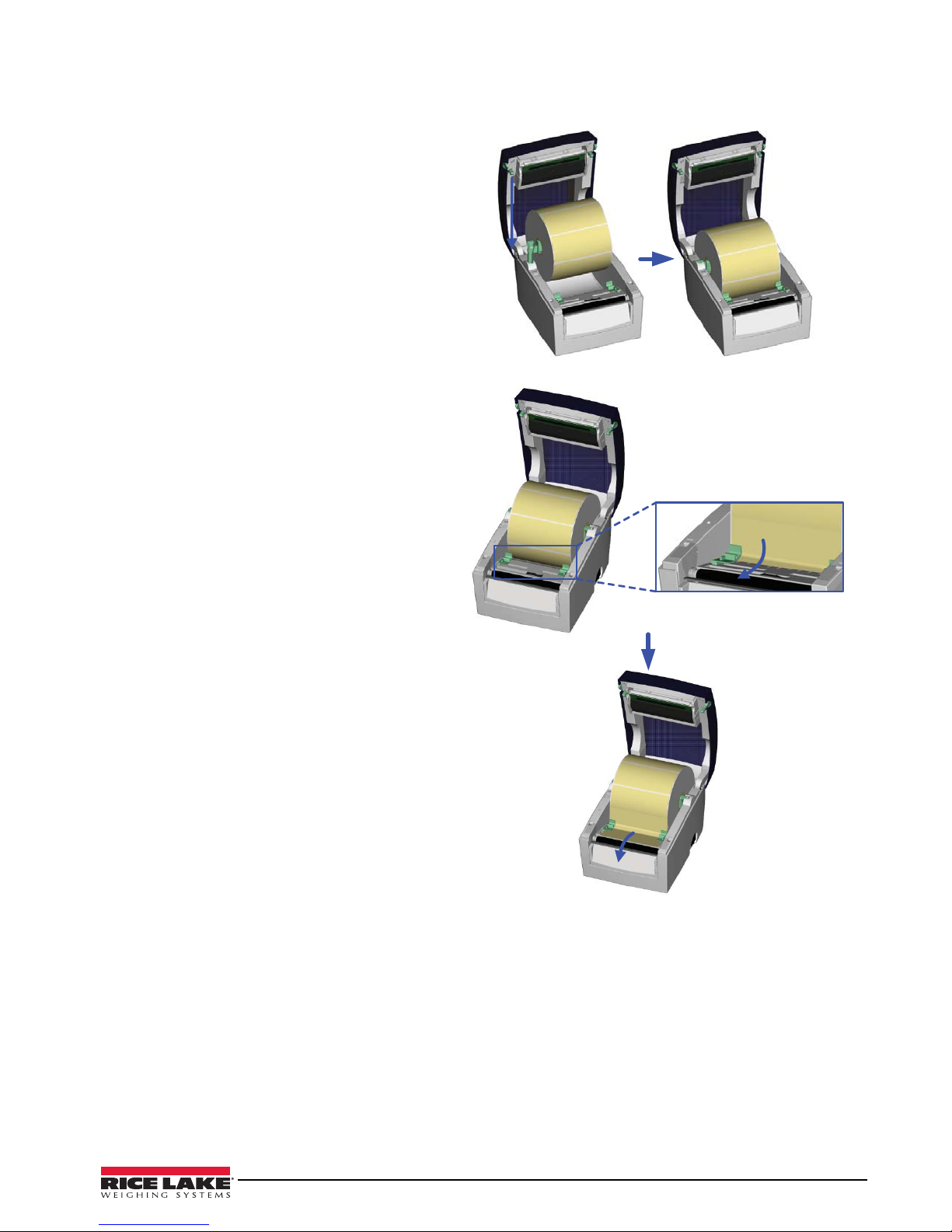
5. Flip the label roll core downward and
pull back the label roll holder.
6. Pull and lock the label roll core to the
original position.
7. Put the label under the label guide and
stretch it frontward.
RL-22DT/RL-42DT Operation Manual - Installation 5
Page 10
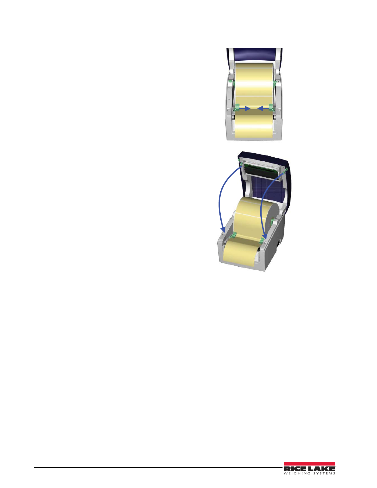
8. Pull the label guide inward and make it
fit the edge of the label.
9. Close the top cover to complete the label
installation.
6 RL-22DT/RL-42DT Operation Manual
Page 11

2.2 Label Roll Core Switch
1” Core
1.5” Core
1. Pull the label roll holder to the topmost
point, then lift the label roll core upward.
2. Turn the label roll core outward as the
figure to the right illustrates.
3. Whirl the label roll core back to the
original position.
NOTES: When the lock hole of the label roll core is on
the upper side, it applies to a 1” core.
When the lock hole of the label roll core is on the lower
side, it applies to a 1.5” core.
You can also distinguish it by the index on the label roll
core as shown in the figure to the right.
RL-22DT/RL-42DT Operation Manual - Installation 7
Page 12

2.3 PC Connection
To connect the printer to a PC, follow these steps:
1. Ensure the printer is powered off.
2. Take the power cable, plug the cable switch to the power socket, then connect the other end of the cable
to the printer power socket.
3. Connect the cable to the USB/Serial port on the printer and an available port on the PC.
4. Power on the printer and the LED light will turn on.
Figure 2-1. PC connection illustration
2.3.1 Store Format - Autoform Capability
1. Design the form in Label View and save it as AUTOFR.
2. Generate a command file.
3. Exit Label View and bring up the file in Dos Edit (the file is AUTOFR.EJF).
4. Add a line at the beginning and add the interrupt command. This is added by holding do wn the CTRL
key and pressing the P, and then the S keys. Two exclamation points should appear at the beginning of
the line.
5. Add before PE the command PA1.
6. Turn the printer off for a minute and then on again to make sure the buffer is empty.
7. Download the form to the printer by choosing Print from Dos Edit.
This is now the form that will be printed every time the print button is pushed. This example works with only one
variable field, which means that only gross or only net weight can be printed. Once this form is loaded in the
printer the customer cannot use the printer any other label format.
2.3.2 Deleting the AUTOFR Form From the Printer
1. Turn the printer off for a minute, then turn it back on.
2. Send the interrupt command, CTRL S, and then FK“*”.
This will delete all stored forms from the printer memory.
This will open up doors for a simple label application, and works with most devices that are sending a single
weight and capable of 9600 baud, 8 data bits.
8 RL-22DT/RL-42DT Operation Manual
Page 13

3.0 Accessories
Note
2
1
Note
3.1 Stripper Module
The stripper module separates a label from its backing, allowing the user to apply a label without peeling.
To install the stripper module, follow these instructions:
1. Make sure you have the module and two
provided screws.
2. Power off the printer before installing the
stripper module.
Label liner thickness is recommended to be
0.06mm ± 10% with basic weight 65g/m2 ±
6%.
The maximum width for the stripper is 110
mm.
When using the stripper module, it is
recommended to set the stop position to 9
in. QLabel and the E value is 9.
3. Place the printer on a horizontal surface
and open the top cover.
4. Remove the front cover piece.
You can use a coin or screwdriver to open
the front cover piece.
RL-22DT/RL-42DT Operation Manual - Accessories 9
Page 14

5. Push the stripper connector into the
Note
printer through the cable hole as shown
in the figure to the right.
6. Place the stripper module on the fillister.
7. Turn the printer around and tighten
screws to secure the stripper module.
8. Unlock the bottom case cover to see the
main board of the printer.
You can use a coin or screwdriver to open
the bottom case cover.
10 RL-22DT/RL-42DT Operation Manual
Page 15

9. Plug the connector into the main board.
Note
There are two sockets on the main board;
one is for the stripper module installation
and the other is for the cutter installation.
Before plugging the connector into the
socket, check the pin first.
10. Lock the bottom case cover.
11. Turn the printer back to proceed with
label installation.
12. Flip the stripper module downward to
open it.
13. Follow the instructions in Section 2.1 on
page 4 to install the label.
RL-22DT/RL-42DT Operation Manual - Accessories 11
Page 16

14. Peel off the first label and feed the liner
through the roller and the striper module
bar.
15. Follow the direction shown in the figure
to the right to feed the liner across the
stripper module.
16. Flip the stripper module upward to close
it.
17. Press the FEED key to adjust the position
of the label and complete the installation.
12 RL-22DT/RL-42DT Operation Manual
Page 17

3.2 Cutter Installation
Note
2
1
Note
The RL-22DT/RL-42DT printers feature a photo-eye, which detects gaps between labels. When a gap is detected,
the cutter will separate the label from the roll. To install the cutter, follow these instructions:
1. Make sure you have the cutter module
and two provided screws.
2. Power off the printer before installing the
cutter module.
Do not cut self-adhesive labels! The traces
of adhesive will pollute the rotary knife and
impair safe operation.
The service life of the cutter is 1,000,000
cuts for paper weights up to 120g/m2, and
500,000 cuts for paper weights 120g/m
170g/m
2
.
3. Place the printer on a horizontal surface
and open the top cover.
2
to
4. Remove the front cover piece.
You can use a coin or screwdriver to open
the front cover piece.
RL-22DT/RL-42DT Operation Manual - Accessories 13
Page 18

5. Push the cutter connector into the printer
Note
through the cable hole as shown in the
figure to the right.
6. Place the stripper module on the fillister.
7. Turn the printer around and tighten
screws to secure the cutter module.
8. Unlock the bottom case cover to see the
main board of the printer.
You can use a coin or screwdriver to open
the bottom case cover.
14 RL-22DT/RL-42DT Operation Manual
Page 19

9. Plug the connector into the main board.
Note
There are two sockets on the main board;
one is for the stripper module installation
and the other is for the cutter installation.
Before plugging the connector into the
socket, check the pin first.
10. Lock the bottom case cover.
11. Turn the printer back to proceed with
label installation.
12. Follow the instructions in Section 2.1 on
page 4 to install the label.
13. Feed the label through the cutter and
press the FEED key to complete the
installation.
RL-22DT/RL-42DT Operation Manual - Accessories 15
Page 20

4.0 Control Panel
Note
The control panel allows access to printer diagnostics and settings. This section provides information on LED
status, the FEED key, self-tests, auto-sensing, dump mode, see-through sensor, and error messages.
4.1 LED Status
Below descriptions apply only to firmware version G3.000 or later.
Press and hold the FEED key then power on the printer, the printer will beep 3 times and enter into Self-Test
status. If you keep holding the FEED key, the status will change in sequence to Auto Sensing Mode, Dump
Mode, See-through Sensor on/off, and then return to Self-Test again. These different statuses can change the
setting of printer; they are described as follows:
LED LIGHT BEEP STATUS DESCRIPTION
Green 1 Standby Mode Normal status
Press and hold the FEED key, then power on the printer.
Red (flash) 3 Auto-Sensing Mode Printing self-test page. For operation
instructions, refer to
Section 4.3 on page 17.
Orange (flash) 1 Auto-Sensing Mode The printer is currently in auto-sensing mode.
For operation instructions, refer to
on page 17.
Green (flash) 1 Dump Mode The printer is currently in dump mode. For
operation instructions, refer to
Orange 1 See-through sensor
on/off
Return to Self-Test
Red (flash) Printer is currently downloading firmware.
Set the see-through sensor on or off. For
operation instructions, refer to
page 18.
page 18.
Section 4.4
Section 4.5 on
Section 4.6 on
Table 4-1.
4.2 Feed Key Introduction
After pressing the FEED key , printer will send the media (according to media type) to the specified stop posi tion.
When printing with continuous media, pressing the FEED key will feed media out to a certain length. When
printing with labels, pressing the FEED key will feed one label at a time. If the label is not sent out in a correct
position, please proceed with the Auto sensing (see
Section 4.4 on page 17).
16 RL-22DT/RL-42DT Operation Manual
Page 21

4.3 Self-Test
LRXXXX : VX.XXX
Serial port :96,N,8,1
1 DRAM installed
Image buffer size : 1500K
000 FORM(S) IN MEMORY
000 GRAPHIC (S) IN MEMORY
000 FONT(S) IN MEMORY
000 ASIAN FONT(S) IN MEMORY
000 DATABASE(S) IN MEMORY
2048K BYTES FREE MEMORY
^S4 ^H10 ^R000 ~R200
^W10 ^Q48,3
Option : ^D0 ^O0 ^AD
See-through Sensor: OFF
Reflective Sensor AD : 146 186 223 (2)
Code Page: 850
Model & Version
Serial port setup
Test pattern
Number of DRAM installed
Image buffer size
Number of forms
Number of graphics
Number of fonts
Number of Asian fonts
Number of Databases
Free memory size
Speed, Density, Ref. Point, Print direction
Label width, Form length
Cutter, Stripper, Mode
See-through Sensor status
Reflective Sensor status
Code Page
Self-Test includes the internal printer data setting.
The Self-Test function in a printer will help user to figure out whether the printer is operating normally. In the
Self-Test Mode, the printer will print out a test sample as below figure. The printer will go back to standby mode
after printing out the test sample. Below are the Self-Test procedures:
1. Power off the printer, then press and hold the FEED key.
2. Power on the printer (while still holding the FEED key); release the FEED key after the printer beeps 3
times.
3. After about 1 second, printer would automatically print out the following. This means the printer is
operating normally.
Figure 4-1. Self-test print page
4.4 Auto-Sensing
The printer can automatically detect the label and store the result of detecting. By doing this, the printer will
calibrate the printing position of the label and the user can print without setting label length. To perform
Auto-Sensing:
1. Check if the label is correctly loaded in the printer.
2. Power off the printer, press and hold the FEED key.
3. Power on the printer (while still holding the FEED key). Keep holding the FEED key , wait until the LED
flashes red and then release the FEED key. The printer will automatically detect the label size/length and
record it.
4. A Self-Test page will be printed after Auto-Sensing is complete. The printer will then return to Standby
mode.
RL-22DT/RL-42DT Operation Manual - Control Panel 17
Page 22

4.5 Dump Mode
Note
When the label setting and the print result don't match, it is recommended to go into the Dump Mode to check for
mistakes in data transmission between the printer and the PC. Test procedures to enter the Dump Mode are as
follows:
1. Power off the printer, press and hold the FEED key.
2. Power on the printer (while still holding the FEED key) and the printer will beep 3 times.
3. Release the FEED key when LED flashes green. Printer will automatically print “DUMP MODE
BEGIN.” This means the printer is in Dump Mode.
4. Send commands to the printer, and check if the print result matches the commands sent.
5. To cancel (get out of the Dump Mode), press the FEED key, the printer will automatically print out
“OUT OF DUMP MODE”. This indicates that printer is back in the standby mode. Powering off the
printer is another way to exit the Dump Mode.
4.6 See-Through Sensor On/Off
There are two types of sensor in RL22DT/RL42DT printer - Reflective Sensor and See-through Sensor. Users
can set one of them as active sensor. By default, the Reflective Sensor is turned on and the See-throug h Sen sor is
turned off. However, the reflective sensor may not be able to detect the label gap on special label materials. For
example, when printing on labels with thick liner, colored liner, or back graphics, then the see-through sensor
would need to be enabled. To turn the See-through Sensor on:
1. Power off the printer, press and hold the FEED key.
2. Power on the printer (while still holding the FEED key) and the printer will beep 3 times. Keep holding
the FEED key, wait for the LED light turn to orange and then release the FEED key. The printers will
automatically print “SEE-THROUGH SENSOR IS ON”. This indicates that the See-Through Sensor is
turned on (and the Reflective Sensor is turned off).
3. To turn off the See-Through Sensor, please repeat above-mentioned procedures. Then the printer will
print “SEE-THROUGH SENSOR IS OFF” to indicate that the See-Through Sensor is turned off.
4. For checking the status of See-through Sensor (on or off), please perform Auto Sensing once. If LED
light is green when doing Auto Sensing, then the See-through Sensor is on. If LED light is orange, then
the See-through Sensor is off.
When the See-through Sensor is enabled, the Label Sensor must be placed in the center of the printer.
4.7 Error Messages
LED LIGHT BEEP DESCRIPTION SOLUTION
Red 4 beeps twice Print head is not firmly closed. Re-open print head and make sure it closes tightly.
Red (flash) None Print head temperature is too high. Wait for the print head temperature to drop to normal range. The
Red 2 beeps twice • Unable to detect paper
• Paper is used up
Red 2 beeps twice Abnormal paper feed Possible causes: card tags or paper fell into the gap behind the
Red 2 beeps twice Memory is full; printer will print “memory full” Delete unnecessary data in the memory by powering the printer
Red 2 beeps twice Can’t find the file; printer will print “Filename
Red 2 beeps twice File name is repeated; printer will print
18 RL-22DT/RL-42DT Operation Manual
cannot be found.”
“Filename is repeated”
Table 4-2. Error messages
printer will go back to standby mode and the LED light will stop
flashing.
• Make sure the movable sensor mark is at the correct
position. If the sensor is still unable to detect paper, repeat
auto-sensing.
• Replace with new label roll.
platen roller; can’t find label gap/black mark; black mark paper
out. Please adjust according to actual usage.
off/on, then sending the P1 command.
Use “~X4” command to print out all the files, then check
whether the file exists and the names are correct.
Change the file name and download again, or delete the file.
Page 23

5.0 Maintenance and Adjustments
Occasionally, you may need to install a new print head, clean the thermal print head, or adjust the cutter.
5.1 Print Head module Installation/Removal
1. Power off the printer before removing or
installing the print head.
2. Open the top cover to see the print head
lift, which is on the left side of the top
cover.
3. Flip the print head lift downward to
release it.
4. The print head bracket can be flipped
downward after the print head lift is
released.
RL-22DT/RL-42DT Operation Manual - Maintenance and Adjustments 19
Page 24

5. Remove the print head connector.
6. Remove the print head screws.
7. From the underneath of the print head
bracket, hold the front end of the print
head to remove it and install a new one.
8. After the new print head is installed,
tighten the print head screws, plug the
print head connector, restore the print
head bracket, and lock the print head lift
to complete installation.
9. Clean the print head to remove any
finger prints, etc.
20 RL-22DT/RL-42DT Operation Manual
Page 25

5.2 Thermal Print Head Cleaning
Note
Unclear printouts may be caused by a dusty print head, ribbon stain, or label liner glue. Therefore, when printing,
it is necessary to keep the top cover closed. Also, check and prevent paper/label from being stained or dusty to
ensure print quality and to prolong the print head life. To clean the print head:
1. Power off the printer.
2. Open the top cover.
3. If there are label pieces or other stains on
the print head (see arrow in figure at
right), use a soft cloth with industrial use
alcohol to wipe away the stain. Make
sure there are no metal or hard particles
on the print head before cleaning.
Weekly cleaning for the print head is
recommended.
5.3 Cutter Adjustment (Paper Jams)
When using the cutter module, paper jams may occur from time to time. Paper jams can be resolved by adjusting
the cutter.
1. Turn the printer around to see the cutter
cover screw.
2. Unscrew the cutter cover screw to
remove the cutter cover.
3. The cutter adjustment screw is on the
side of the cutter. Use a screwdriver to
turn the cutter adjustment screw
counter-clockwise for releasing the
paper-knife of the cutter. Then, remove
the jammed label.
4. After the jammed label is removed, turn
the cutter adjustment screw clockwise to
restore the paper-knife.
RL-22DT/RL-42DT Operation Manual - Maintenance and Adjustments 21
Page 26

6.0 Appendix
Note
6.1 Control Commands
Dump Mode
Syntax ~S,DUMP
Parameter None
Description When the printout result doesn’t match to the label format setting, it is recommended to go into the Dump Mode to
ˆGn - Enable/Disable See-Through Sensor
Syntax ˆGn
Parameter n = 0, disable see-through sensor
Description The reflective sensor may not be able to detect the label gap on special label materials. For example, when printing on
troubleshoot data transmission between the printer and the PC. When in Dump Mode, the printer will not process
commands; it will only print out the contents of the commands. This will confirm whether the commands were received
correctly. To get out from the Dump Mode, please press the FEED key, and then the printer will automatically print out “OUT
OF DUMP MODE” and return to standby mode. You can also power off the printer to exit Dump Mode.
Table 6-1. Dump mode
n = 1, enable see-through sensor
n = 2, Auto Mode
labels with thick liner, colored liner, or back graphics, the see-through sensor would need to be enabled since the reflective
sensor may not work correctly.
When the see-through sensor is enabled, the moveable sensor must be placed in the center of the printer.
Table 6-2. See-through sensor
ˆHx - Print Darkness Setting
Syntax ˆHx
Parameter x = 00 ~ 19
Description Sets the darkness of printing
Table 6-3. Print darkness setting
22 RL-22DT/42-DT Operation Manual
Page 27

6.2 Specifications
Feature RL-22DT RL-42DT
Resolution 203 dpi (8 dot/mm)
Print Mode Direct Thermal
CPU 32 Bit
Memory 4MB Flash, 8MB SDRAM
Print Speed 2 IPS ~ 4 IPS
Print Length Max.1727mm (68") Min.12.7mm(0.5")
Print Width Max.54 mm (2.12") Max.108 mm (4.25")
Sensor Type Adjustable Reflective sensor; Fixed transmissive, center aligned
Sensor Detection Type: Label gap and black mark sensing.
Detection: Label length auto sensing and / or program command setting
Media Label Roll OD: Max. 127mm (5")
Core Diameter: 1" (25 mm), 1.5" (40 mm)
Width: 15 mm (0.6 ") ~ 60 mm (2.36")
Thickness: 0.06~0.20 mm
Printer Language EZPL (Firmware downloadable)
Resident Fonts 9 resident Windows bit mapped fonts (6, 8,10,12,14,18,24,30 and 16X26), can be rotated in 8 orientations and
expandable 8 times horizontally and vertically.
Scalable Font (Code Page 850 & 852) in 4 orientations.
Fonts Download Windows bit mapped font: can be rotated in 8 orientations and expandable 8 times horizontally and vertically.
Asian font: can be rotated in 4 orientations and expandable 8 times horizontally and vertically.
True Type Font: can be rotated in 4 orientations.
Image Handling BMP, PCX, Support ICO, WMF, JPG, EMF file through software.
Barcodes Code 39, Code 93, Code 128 (subset A, B, C), UCC/EAN-128 K-Mart, UCC/EAN-128, UPC A / E (add on 2 & 5), I 2 of
5, I 2 of 5 with Shipping Bearer Bars, EAN 8 / 13 (add on 2 & 5), Codabar, Post NET, EAN 128, DUN 14, MaxiCode,
HIBC, Plessey, Random Weight, Telepen, FIM, China Postal Code, RPS 128, PDF417, Datamatrix code & QR code
Interfaces Serial port: RS-232 ( Baud rate : 4800 ~ 115200 , XON/XOFF , DSR/CTS )
USB port: V2.0
Control Panel One Tri-color LED: Power
Function Key: FEED
Power Auto Switching 100/240VAC, 50/60 Hz
Environment Operation: 41°F to 104°F (5°C to 40°C)
Storage: -4°F to 122°F (-20°C to 50°C)
Cert. Approval CE, FCC Class A, CCC, CB, cUL, BSMI
Humidity Operation: 30-85%, non-condensing. Free air.
Storage: 10-90%, non-condensing. Free air.
Printer Dimensions Length: 218 mm (8.58")
Height: 172 mm (6.77")
Width: 100 mm (3.94")
Weight: 1.2 Kg
Options Rotary Cutter Module
Stripper Module
RTC
Internal Ethernet Adapter Card
Label Roll OD: Max. 127mm (5")
Core Diameter: 1" (25 mm), 1.5" (40 mm)
Width: 25 mm (1 ") ~ 118 mm (4.65")
Thickness: 0.06~0.20 mm
Length: 218 mm (8.58")
Height: 166 mm (6.53")
Width: 168 mm (6.61")
Weight: 1.5 Kg
Rotary Cutter Module
Stripper Module
Internal Ethernet Adapter Card
Parallel port
Table 6-4. Printer specifications
RL-22DT/42-DT Operation Manual - Appendix 23
Page 28

6.3 Compliance Statements
Warning
FCC COMPLIANCE STATEMENT FOR AMERICAN USERS
This equipment has been tested and found to comply with the limits for a CLASS A digital de vice, pursuant to
Part 15 of the FCC Rules. These limits are designed to provide reasonable protection against harmful
interference when the equipment is operated in a commercial environment. This equipment generates, uses, and
can radiate radio frequency energy and, if not installed and used in accordance with the instructions, may cause
harmful interference to radio communications. Operation of this equipment in a residential area is likely to cause
harmful interference in which case the user will be required to correct the interference at own expense.
EMS AND EMI COMPLIANCE STATEMENT FOR EUROPEAN USERS
This equipment has been tested and passed with the requirements relating to electromagnetic compatibility based
on the standards EN 55022:1998+A1:2000+A2:2003, CISPR 22, Class A EN 55024:1998+A1:2001+A2:2003,
IEC 61000- 4 Series EN 61000-3-2 / 2000 & EN 61000-3-3 / 1995. The equipment also tested and passed in
accordance with the European Standard EN55022 for the both Radiated and Conducted emissions limits.
RICE LAKE SERIES TO WHICH THIS DECLARATION RELATES IS IN CONFORMITY WITH THE FOLLOWING STANDARDS
EN55022 : 1998,CLSPR 22, Class A / EN55024 : 1998IEC 61000-4 Serial / EN61000-3-2 : 2000 / EN 6100-3-3
: 1995 / CFR 47, Part 15/CISPR 22 3rd Edition : 1997, Class A / ANSI C63.4 : 2001 / CNS 13438 / IEC60950-1
: 2001 / GB4943 : 2001 / GB9254 : 1998 / GB17625.1 : 2003 /EN60950-1 : 2001
Danger of explosion if battery is incorrectly replaced
Replace only with the equivalent type recommended by the manufacture.
Dispose of used batteries according to the manufacturer's instructions.
24 RL-22DT/42-DT Operation Manual
Page 29

6.4 Serial Interface
Note
The serial default setting is: 9600 baud rate, no parity,
8 data bits, 1 stop bit, and XON/XOFF protocol.
The total current output from the serial port
cannot exceed 500mA.
PC PRINTER
DB9 Socket DB9 Plug
--- 1_____________1 +5V, max 500mA
RXD 2_____________2 TXD
TXD 3_____________3 RXD
DTR 4_____________4 N/C
GND 5_____________5 GND
DSR 6_____________6 RTS
RTS 7_____________7 CTS
CTS 8_____________8 RTS
RI 9_____________9 N/C
Table 6-5. RS232 Housing (9-pin to 9-pin)
6.5 USB Interface
RL-22DT/RL-42DT printers use a Type B connector
type.
Pin Number 1 2 3 4
Function VBUS D- D+ GND
Table 6-6. USB interface Specs
6.6 Internal Interface
.
UART1 wafer Ethernet module
N.C 1_____________1 N.C
TXD 2_____________2 RXD
RXD 3_____________3 TXD
CTS 4_____________4 RTS
GND 5_____________5 GND
RTS 6_____________6 CTS
E_MD 7_____________7 E_MD
RTS 8_____________8 CTS
E_RST 9_____________9 E_RST
+5V 10____________10 +5V
GND 11____________11 GND
+5V 12____________12 +5V
Table 6-7. Internal interface specs
6.7 Troubleshooting
Symptom Remedy
LED light is not lit Check the power connector
LED light indicates error
messages after printing
stops
Nothing is printed on
label
Label is jammed Clean the label jam; if the label is stuck on
Only some of the
contents is printed
Part of the label isn’t
printed completely
Printout is not in the
desired position
Page skipping occurs • Check if error occurs on label height
Unclear printout • Check print darkness setting
Label isn’t cut straight Check if label is set up straight
Label isn’t cut Make sure label thickness does not exceed
Label couldn’t feed or
unexpected cutting
occurs
The stripper module isn’t
working correctly
• Check for software setting or
program command errors
• Replace with suitable label
• Check if label may run out
• Check if label is jammed/tangled up
• Check if mechanism is closed
(Thermal Print Head not positioned
correctly)
• Check if sensor is blocked by label
• Check for abnormal cutter function or
of no actions (if cutter is installed)
• Check if label is placed upside down
or if label is not suitable for the
applicationSelect the correct printer
driver
• Select the correct label and print type
the thermal print head, remove by using a
soft cloth and alcohol
• Check if label is stuck on the Thermal
Print Head
• Check if application software has
errors
• Check if start position setting has
errors/paper width/length
• Check if power supply is correct
• Check if Thermal Print Head is
stained or dusted
• Use internal command “~T” to check
Thermal Print Head can print
completely
• Check the media quality/size
• Check if sensor is covered by paper
or dust
• Check if liner is suitable for use,
please contact reseller for more
information
• Check if label roll edge is aligned with
Label Width Guide
setting
• Check if sensor is covered by dust
• Check if Thermal Print Head is
covered with glue or stain
0.16 mm
• Check if cutter is installed properly
• Check if paper feed is working
normally
• Check if stripper module sensor is
covered with dust
• Check if label is installed properly
Table 6-8. Troubleshooting
RL-22DT/42-DT Operation Manual - Appendix 25
Page 30

RL-22DT/42-DT Limited Warranty
Rice Lake Weighing Systems (RLWS) warrants that all RLWS equipment and systems properly installed by a
Distributor or Original Equipment Manufacturer (OEM) will operate per written specifications as confirmed by
the Distributor/OEM and accepted by RLWS. All systems and components are warranted against defects in
materials and workmanship for two years.
RLWS warrants that the equipment sold hereunder will conform to the current written specifications authorized
by RLWS. RLWS warrants the equipment against faulty workmanship and defective materials. If any equipment
fails to conform to these warranties, RLWS will, at its option, repair or replace such goods returned within the
warranty period subject to the following conditions:
• Upon discovery by Buyer of such nonconformity, RLWS will be given prompt written notice with a
detailed explanation of the alleged deficiencies.
• Individual electronic components returned to RLWS for warranty purposes must be packaged to
prevent electrostatic discharge (ESD) damage in shipment. Packaging requirements are listed in a
publication, Protecting Your Components From Static Damage in Shipment, available from RLWS
Equipment Return Department.
• Examination of such equipment by RLWS confirms that the nonconformity actually exists, and was
not caused by accident, misuse, neglect, alteration, improper installation, improper repair or
improper testing; RLWS shall be the sole judge of all alleged non-conformities.
• S uch equipment has not been modified, altered, or changed by any person other than RLWS or its
duly authorized repair agents.
• RLWS will have a reasonable time to repair or replace the defective equipment. Buyer is responsible
for shipping charges both ways.
• In no event will RLWS be responsible for travel time or on-location repairs, including assembly or
disassembly of equipment, nor will RLWS be liable for the cost of any repairs made by others.
THESE WARRANTIES EXCLUDE ALL OTHER WARRANTIES, EXPRESSED OR IMPLIED, INCLUDING WITHOUT
LIMITATION WARRANTIES OF MERCHANTABILITY OR FITNESS FOR A PARTICULAR PURPOSE. NEITHER
RLWS
NOR DISTRIBUTOR WILL, IN ANY EVENT, BE LIABLE FOR INCIDENTAL OR CONSEQUENTIAL DAMAGES.
RLWS AND BUYER AGREE TH AT RLWS’S SOLE AND EXCLUSIVE LIABILITY HEREUNDER IS LIMITED TO
REPAIR OR REPLACEMENT OF SUCH GOODS. IN ACCE PT ING THIS WARRANTY, THE BUYER WAIVES ANY AND
ALL OTHER CLAIMS TO WARRANTY.
SHOULD THE SELLER BE OTHER THAN RLWS, THE BUYE R AGREES TO LOOK ONLY TO THE SELLER FOR
WARRANTY CLAIMS.
NO TERMS, CONDITIONS, UNDERSTANDING, OR AGREEMENTS PURPORTING TO MODIFY THE TERMS OF THIS
WARRANTY SHALL HAVE ANY LEGAL EFFECT UNLESS MADE IN WRITING AND SIGNED BY A CORPORATE
OFFICER OF RLWS AND THE BUYER.
© 2011 Rice Lake Weighing Systems, Inc. Rice Lake, WI USA. All Rights Reserved.
RICE LAKE WEIGHING SYSTEMS • 230 WEST COLEMAN STREET • RICE LAKE, WISCONSIN 54868 • USA
26 RL-22DT/42-DT Operation Manual
Page 31

Page 32

PN 108222 02/11
 Loading...