

Page 1
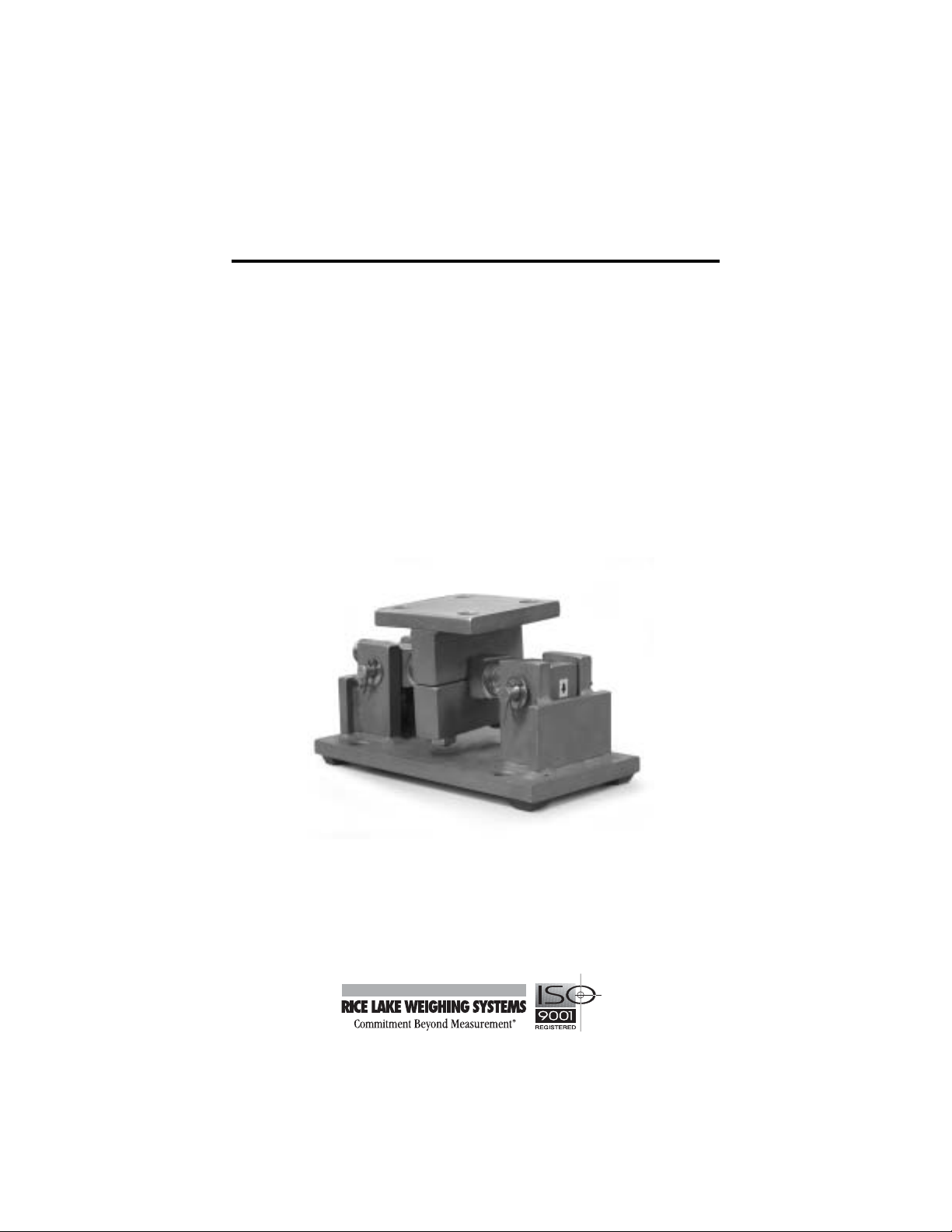
RL1600
Weigh Module Kit
Installation
Guide
11
16952
Page 2

Contents
1. Introduction ............................................................................ 1
2. Mechanical Installation.......................................................... 2
2.1 General Installation Guidelines for Weigh Modules....................2
2.2 Installing the RL1600..................................................................3
3. Load Cell Wiring..................................................................... 5
4. Junction Box Connections, Adjustments & Calibration..... 6
5. Troubleshooting..................................................................... 6
6. Maintenance and Replacement Parts................................... 8
7. RL1600 Limited Warranty.................................................... 10
© 2004 Rice Lake Weighing Systems. All rights reserved.
Printed in the United States of America.
Specifications subject to change without notice.
02/04
Page 3
1. Introduction
The RL1600 Weigh Module Kit provides an extremely accurate method for
weighing medium and large capacity tanks, hoppers, bins, and reactors. The design
uses a double-ended shear beam load cell (700Ω bridge) and transmits the load
through a clamping load plate to the center of the load cell. This design is very
effective in providing for thermal expansion/contraction with little friction.
In the majority of applications, the modules are
self-checking and held captive with no need for
check or stay rods, making this mount a good
choice for areas with frequent seismic activity.
The RL1600 is available in cast iron, mild steel, or
stainless steel in sizes from 1,000-75,000lb. The
module is compatible with RL75016, RL75016
Stainless Steel, RL75016HE, Sensortronics 65016
and Sensortronics 65016W Stainless Steel load
cells in capacities from 1,000 lb to 75,000 lb.
Thermal
Expansion
Caution
The installation should be planned by a qualified structural
engineer. Each installation is unique, and this manual is meant
to serve only as a general guideline for installation.
Authorized distributors and their employees can
view or download this manual from the Rice Lake
Weighing Systems distributor site at www.rlws.com.
1
Page 4
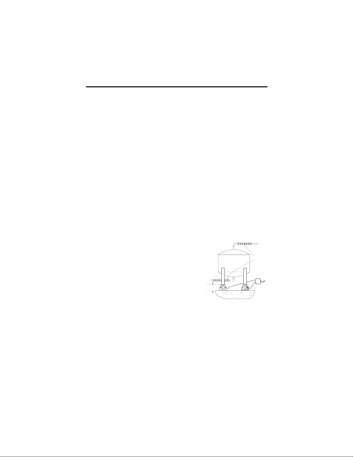
2. Mechanical Installation
LEVEL ±0.5°
FLEXIBLE PIPING
J-BOX
2.1 General Installation Guidelines for Weigh Modules
1. The mounting surface for the base and top plate must be level. After installation,
the top and bottom plates must be level within ±0.5°. If the mounting surfaces
are not level, then shims and or grout may be used to level the mount.
If possible, check that the module is level when the vessel is fully loaded
because excessive deflections in legs and supporting structures may cause
additional side forces which greatly affect accuracy. Deflection of the mount’s
top or base plate due to loading should not exceed ±.5°. Reinforcement of legs
or other support structures may be necessary to correct this. Vessels with long
legs should have cross bracing applied between adjacent legs to keep them from
spreading under load.
2. Compression mounting systems use three, four, or more mounts. More than
eight-module systems should be avoided as even weight distribution becomes
extremely difficult to achieve. The load on each module should vary by no more
than 20%. During installation, add shims where necessary to achieve correct
load distribution.
3. If the actual load cells are used during installation of the weigh module, extreme
care must be taken to prevent overload damage. A tank or hopper weighing
several tons can exert huge forces when dropped only a fraction of an inch.
Dummy load cells can be used during installation.
4. It is crucial that all piping or conduit be horizontal and flexible. If flexible piping is not
used, make sure the distance from the vessel to
the first pipe support is 20-30 times the pipe
diameter.In smaller, lower capacity tanks and
hoppers, isolating the resultant forces becomes
extremely critical. For details, see our Weigh
Modules & Vessel Weighing Systems manual,
PN 43918.
5. Load cells should not be installed in the modules until all welding is completed. The heat generated from welding current
passing through a load cell can damage the adhesive holding the strain gauge
to the body. If possible, use a dummy load cell when welding to maintain
finished height. If welding is unavoidable after load cell installation, connect
the ground in such a way that the current does not flow through the load cell.
For example, if welding on the module top plate, the ground must be connected
to the vessel, not to the mount base or support structure. Also, protect the load
cell and cable from weld splatter.
6. When possible, use only “hermetically sealed” load cells in washdown applications. “Environmentally protected” load cells are not suitable for such
applications and will be damaged. If tanks and surrounding equipment are
2
Page 5

frequently steam cleaned or if the load cell is subjected to direct washdown,
a protective shroud for the weigh module is recommended. Proper drainage is
necessary so the weighing assembly is not standing in water.
7. All support points should be equally stiff so that they deflect by the same
amount as the vessel is loaded.
2.2 Installing the RL1600
Load Plate and Clamp
Pin
Cotter Pin
Flat Washer
Load Cell
Lockwasher
Clamp Bolt
Tank Mount Base
1. The type of installation and strength of the mounting surface governs the
method of locating, attaching, and assembling the RL1600 assembly. Carefully
consider three areas that commonly cause accuracy problems:
•Are the supporting legs adequately braced so they will not spread when the
system is fully loaded?
•Does the supporting structure have the necessary strength to prevent
excessive deflection when the system is fully loaded?
• Is there attached equipment such as skirting, venting, or piping which is
likely to cause binding or lack of flexibility?
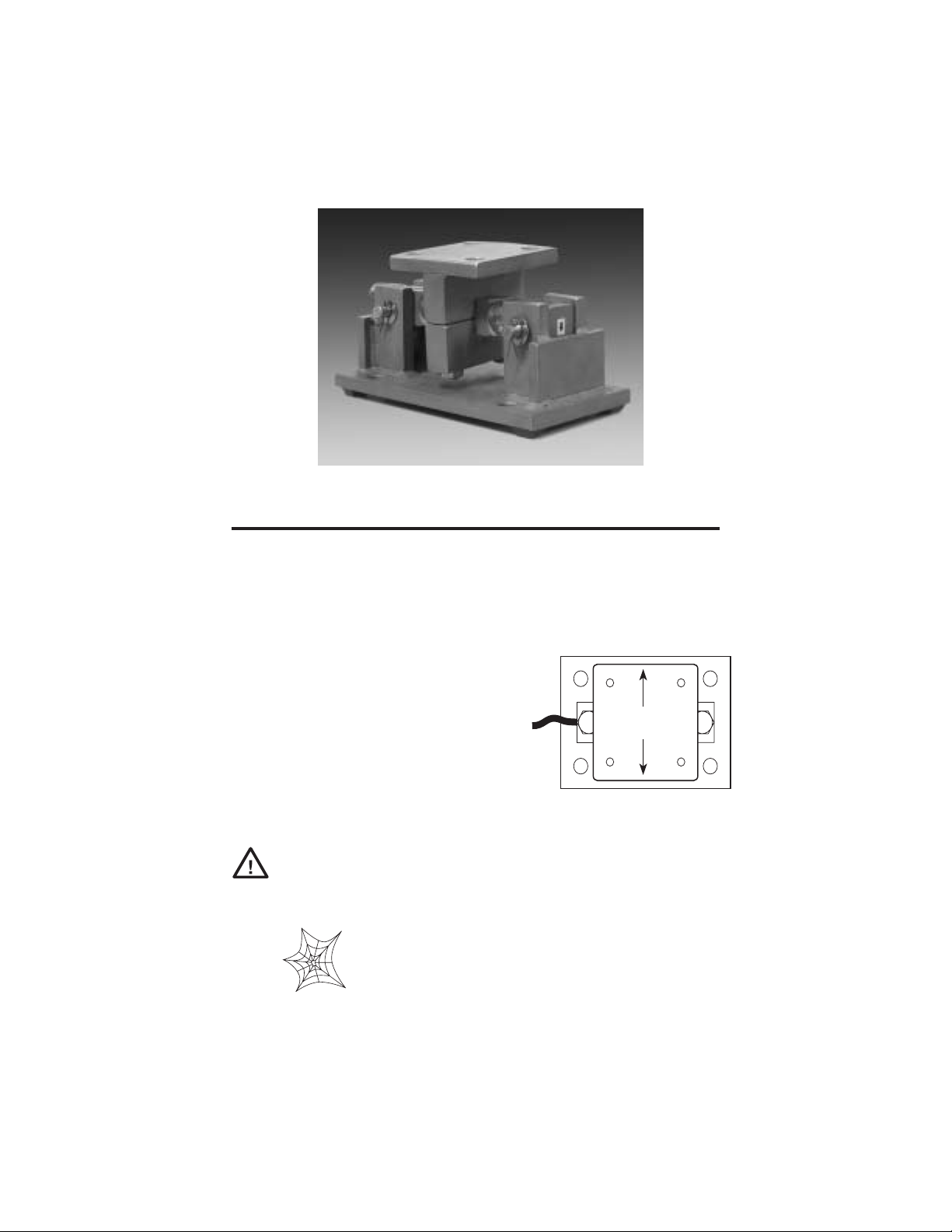
2. Determine where to position the module and in which direction it should be
oriented. The RL1600 is designed to allow for lateral movement in the direction
perpendicular to the longitudinal axis of the load cell. These weigh modules
should be oriented so that the movement due to thermal expansion/contraction
is perpendicular to the longitudinal axis. Sample mounting orientations to
accommodate expansion for different vessel shapes are as follows:
3
Page 6

3. Assemble the modules by attaching the load cell to the load plate and clamp
using the lockwashers and clamp screws. Then, insert the load pins through the
base plate and load cell. Secure the load pins with washers and cotter pins.
Note: The arrow on the load cell should point in the direction of the load.
4. Lift and block the vessel to the same height as the assembled modules.
5. Remove the block from one support point and slide that module into position.
6. As the module is being fitted under the leg of the vessel, verify that the leg’s
center line passes through the center of the load plate (through the center of the
load cell).
7. Lower the corner or side of the vessel carefully onto the load plate.
Use extreme care when lowering the vessel. The
Caution
8. With the load plate positioned approximately level, mark holes for attaching
the load plate to the vessel’s mounting surface. Make holes and attach the load
plate loosely to vessel with suitable fasteners.
9. Repeat steps 5-8 for the weigh modules at the remaining corners or sides.
10. Verify that there is no initial misalignment between the tank mount base and
load plate and clamp and that the load plate and clamp is centered with respect
to the load cell. Also, verify that the load cell, clamp, and load cell assembly is
centered in the base plate. Relocate if necessary.
force of a vessel weighing several tons can damage a load cell if dropped only a fraction of an inch.
11. Attach the base plates to the foundation using suitable anchors for concrete or
by bolting or welding to a steel structure or subplate. Verify that the base plates
are no more than ±.5° out of level. Shim as necessary.
12. Check that the top plates are no more than ±.5° out or level. Shim if necessary
and fully tighten mounting bolts.
13. IMPORTANT: Check that each pin of each module has approximately equal
weight applied. If a pin is loose, shim between the base plate and foundation as
necessary.
14. If dummy cells are used, replace with the load cells. Refer to step 3.
15. To achieve equal load distribution, final height adjustments can be made with
shims between the load plate and clamp and the vessel. The variation in load
among the cells should be no more than 20%. The load distribution can be
checked accurately by exciting each load cell in turn and measuring the output
with a voltmeter.
4
Page 7

3. Load Cell Wiring
1. Route the load cell cables so they will not be damaged or cut. Cable should not
be routed near heat sources greater than 150 °F. Do not shorten any load cell
cable. The load cell is temperature compensated with the supplied length of
cable. Cutting the cable will affect temperature compensation. Coil and protect
excess cable so it will not be mechanically damaged or be sitting in water.
2. Provide a drip loop in all cables so that water or other liquids will not run
directly down the cables onto either the load cells or the junction box. Attach
load cell cable to the dead structure, not the vessel.
3. If conduit protection is necessary against mechanical or rodent damage to the
load cell cables, use flexible conduit and conduit adapters at the load cells.
4. Connect cables for standard RL75016, RL75016 Stainless Steel, RL75016HE,
Sensortronics 65016 and Sensortronics 65016W Stainless Steel load cells to
the summing board in the junction box according to the guide shown below and
the labels on the terminal strips of the junction box. To verify the wiring
scheme, see the certification shipped with each load cell.
5. For better performance, use positive and negative remote sense lines if the
wiring running from the junction box to the indicator is longer than 25 feet.
ROLOCERIWLLECDAOL NOITCNUF
deRCXE+
kcalBCXE–
neerGGIS+
etihWGIS–
eraBroyarGDLEIHS
5
Page 8

4. Junction Box Connections, Adjustments & Calibration
1. Refer to the Junction Box manual for trimming details.
2. Refer to the indicator manual for system calibration details.
5. Troubleshooting
If the system powers up and gives some type of stable digital readout that varies
with the load on the system, any system problems are probably caused by factors
other than the load cells. The load cells are often blamed for a malfunctioning
system, but 90% of the time, the problem lies elsewhere. Look for mechanical
causes for your problem first.
If the system can be calibrated but doesn’t return to zero, loses calibration, or
demonstrates non-linearity or non-repeatability, see the following chart for possible causes and do the following checks.
motpmySmotpmyS
motpmySmotpmyS esuaCelbissoPesuaCelbissoP
motpmyS
orezotnruteroN noitarbilacmetsystsolevahyam;sllecdaolrednuroslaesnisirbedrognidniblacinahceM
ytiraenil-noN daoledisrognidnibgnisuacdaolrednunoitcelfedronoisnapxelamrehT
ytilibataeper-noN
noitarbilactsoL gnidniblacinahcem;melborperutsiom;bmulprolevelfotuO
tuodaergnitfirD gnidniblacinahcem;llecdaolro,selbac,xobnoitcnujnierutsioM
esuaCelbissoPesuaCelbissoP
esuaCelbissoP
gnidniblacinahcem
;egamadkcohsrodaolrevollecdaol,erutsiomybdesuacgnitfird;tnuomllecdaolesooL
1. Check weigh module for debris restricting load cell movement or debris
between scale and structure.
2. Check that tank/vessel and modules are plumb, level, and square at the
critical areas.
3. Check all piping and conduit for connections which restrict vessel
movement.
4. If check rods are used, loosen all connections to finger tight only for
testing.
5. Check load cell cables for physical or water damage.
6. Check all electrical connections, especially in the junction box.
If the problem still is not found:
6
Page 9

7. Check possible indicator malfunction by using a load cell simulator to
input a known good signal into the indicator.
8. Disconnect each load cell’s signal leads at the junction box and check
individual load cell outputs with a multimeter. Then check input/output
impedances for comparison with load cell manufacturer’s specifications.
If after all these checks the problem still cannot be isolated, reconnect all but one
load cell. Replace the load cell with a load cell simulator. Alternate so that each load
cell is individually disconnected and replaced with a simulator. If there is a problem
with a particular load cell, the symptom should disappear when that load cell is
disconnected and replaced with the simulator.
7
Page 10

6. Maintenance and Replacement Parts
3
8
4
6
7
2
5
1
RL1600 CAST IRON MODULES
No. Description Reqd. Replacement Part Numbers
A* B*
1 ... Weigh Module Base ................... 1 ............ 18439......... 18441
2 ... Washer ....................................... 4 ............ 15165......... 15179
3 ... Load Plate and Clamp ................ 1 ............ 18443......... 18445
4 ... Cotter Pin.................................... 4 ............ 15232......... 15237
5 ... Pin............................................... 2 ............ 18449......... 18448
6 ... Lock Washer............................... 2 ............ 15167......... 15181
7 ... Clamp Bolt .................................. 2 ............ 15080......... 15099
8 ... Load Cell .................................... see Load Cell Product Selection Guide
*A-size mounts use load cells with capacities from 1,000-5,000 lb.
*B-size mounts use load cells with capacities from 10,000-25,000 lb.
8
Page 11

3
4
6
7
8
2
5
1
RL1600 MILD STEEL MODULES
No. Description Reqd. Replacement Part Numbers
A* B* C* D*
1 ... Weigh Module Base ................... 1 ....... 22745.. 22748... 22751 .. 22751
2 ... Washer ....................................... 4 .......15165 .. 15179...15188 .. 15188
3 ... Load Plate and Clamp ................ 1 ....... 22746.. 22749... 22752 .. 25364
4 ... Cotter Pin.................................... 4 ....... 15232 .. 15237... 15257 .. 15257
5 ... Pin............................................... 2 ....... 22747 .. 22750... 22753 .. 22753
6 ... Lock Washer............................... 2 .......15167 .. 15181 ...15189 .. 15189
7 ... Clamp Bolt .................................. 2 ....... 14757 .. 15097...14799 .. 14799
8 ... Load Cell .................................... see Load Cell Product Selection Guide
*A-size modules use load cells with capacities from 1,000-5,000 lb.
*B-size modules use load cells with capacities from 10,000-25,000 lb.
*C-size modules use load cells with a capacity of 50,000-75.000 lb.
*D-size modules use load cells with a capacity of 75,000 lb.
RL1600 STAINLESS STEEL MODULES
No. Description Reqd. Replacement Part Numbers
A* B* C* D*
1 ... Weigh Module Base ................... 1 ....... 22754.. 22756... 10124 .. 10124
2 ... Washer ....................................... 4 .......15166 .. 15180...15188 .. 15188
3 ... Load Plate and Clamp ................ 1 ....... 22755.. 22757... 10128 .. 25365
4 ... Cotter Pin.................................... 4 ....... 15233 .. 15238... 15258 .. 15258
5 ... Pin............................................... 2 ....... 22747 .. 22750... 22753 .. 22753
6 ... Lock Washer............................... 2 .......15168 .. 15182 ...15189 .. 15189
7 ... Clamp Bolt .................................. 2 ....... 14758 .. 15098...14800 .. 14800
8 ... Load Cell .................................... see Load Cell Product Selection Guide
*A-size modules use load cells with capacities from 1,000-5,000 lb.
*B-size modules use load cells with capacities from 10,000-25,000 lb.
*C-size modules use load cells with a capacity of 50,000-75.000 lb.
*D-size modules use load cells with a capacity of 75,000 lb.
9
Page 12

7. RL1600 Limited Warranty
Rice Lake Weighing Systems (RLWS) warrants that all RLWS equipment and systems
properly installed by a Distributor or Original Equipment Manufacturer (OEM) will operate
per written specifications as confirmed by the Distributor/OEM and accepted by RLWS. All
weigh modules are warranted against defects in materials and workmanship for two (2) years.
RLWS warrants that the equipment sold hereunder will conform to the current written
specifications authorized by RLWS. RLWS warrants the equipment against faulty workmanship and defective materials. If any equipment fails to conform to these warranties, RLWS
will, at its option, repair or replace such goods returned within the warranty period subject
to the following conditions:
•
Upon discovery by Buyer of such non-conformity, RLWS will be given prompt
written notice with a detailed explanation of the alleged deficiencies.
• Individual electronic components returned to RLWS for warranty purposes must be
packaged to prevent electrostatic discharge (ESD) damage in shipment. Packaging
requirements are listed in a publication, “Protecting Your Components From Static
Damage in Shipment,” available from RLWS Equipment Return Department.
• Examination of such equipment by RLWS confirms that the non-conformity actually
exists, and was not caused by accident, misuse, neglect, alteration, improper installa
tion, improper repair or improper testing; RLWS shall be the sole judge of all alleged
non-conformities.
• Such equipment has not been modified, altered, or changed by any person other than
RLWS or its duly authorized repair agents.
RLWS will have a reasonable time to repair or replace the defective equipment.
•
Buyer is responsible for shipping charges both ways.
• In no event will RLWS be responsible for travel time or on-location repairs, including
assembly or disassembly of equipment, nor will RLWS be liable for the cost of any
repairs made by others.
THESE WARRANTIES EXCLUDE ALL OTHER WARRANTIES, EXPRESSED OR
IMPLIED, INCLUDING WITHOUT LIMITATION WARRANTIES OF MERCHANTABILITY OR FITNESS FOR A PARTICULAR PURPOSE. NEITHER RLWS NOR
DISTRIBUTOR WILL, IN ANY EVENT, BE LIABLE FOR INCIDENTAL OR CONSEQUENTIAL DAMAGES.
RLWS AND BUYER AGREE THAT RLWS’S SOLE AND EXCLUSIVE LIABILITY
HEREUNDER IS LIMITED TO REPAIR OR REPLACEMENT OF SUCH GOODS. IN
ACCEPTING THIS WARRANTY, THE BUYER WAIVES ANY AND ALL OTHER
CLAIMS TO WARRANTY.
SHOULD THE SELLER BE OTHER THAN RLWS, THE BUYER AGREES TO LOOK
ONLY TO THE SELLER FOR WARRANTY CLAIMS.
No terms, conditions, understanding, or agreements purporting to modify the terms of this
warranty shall have any legal effect unless made in writing and signed by a corporate officer
of RLWS and the Buyer.
© 2004 Rice Lake Weighing Systems, Inc. Rice Lake, WI USA. All Rights Reserved.
RICE LAKE WEIGHING SYSTEMS • 230 WEST COLEMAN STREET
RICE LAKE, WISCONSIN 54868 • USA
10
 Loading...