

Page 1
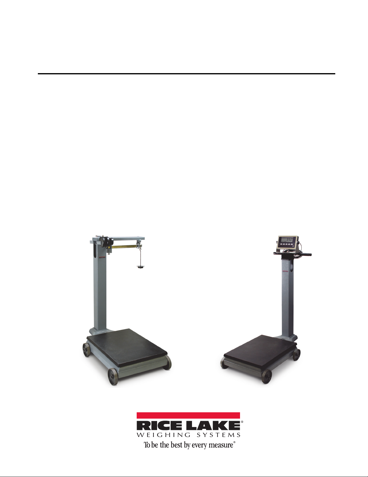
RL1200
Portable Beam Scale
Installation & Operation
Manual
157986
Page 2

Page 3

Contents
Technical training seminars are available through Rice Lake Weighing Systems.
Course descriptions and dates can be viewed at www.ricelake.com/training
or obtained by calling 715-234-9171 and asking for the training department.
1.0 Introduction.................................................................................................................................. 1
1.1 Safety . . . . . . . . . . . . . . . . . . . . . . . . . . . . . . . . . . . . . . . . . . . . . . . . . . . . . . . . . . . . . . . . . . . . . . . . 2
1.2 Safety Signals. . . . . . . . . . . . . . . . . . . . . . . . . . . . . . . . . . . . . . . . . . . . . . . . . . . . . . . . . . . . . . . . . . 2
1.3 Safety Precautions . . . . . . . . . . . . . . . . . . . . . . . . . . . . . . . . . . . . . . . . . . . . . . . . . . . . . . . . . . . . . . 2
2.0 Installation Instructions............................................................................................................... 3
2.1 Unpacking the Scale . . . . . . . . . . . . . . . . . . . . . . . . . . . . . . . . . . . . . . . . . . . . . . . . . . . . . . . . . . . . 3
2.2 Repacking. . . . . . . . . . . . . . . . . . . . . . . . . . . . . . . . . . . . . . . . . . . . . . . . . . . . . . . . . . . . . . . . . . . . . 4
2.3 Setting Up Your Scale . . . . . . . . . . . . . . . . . . . . . . . . . . . . . . . . . . . . . . . . . . . . . . . . . . . . . . . . . . . 5
2.3.1 Assemble Wheels onto Frame. . . . . . . . . . . . . . . . . . . . . . . . . . . . . . . . . . . . . . . . . . . . . . . . . . . . . . . . 5
2.3.2 Attach Pillar to Scale Base . . . . . . . . . . . . . . . . . . . . . . . . . . . . . . . . . . . . . . . . . . . . . . . . . . . . . . . . . . 7
2.3.3 Trig Loop Assembly . . . . . . . . . . . . . . . . . . . . . . . . . . . . . . . . . . . . . . . . . . . . . . . . . . . . . . . . . . . . . . 10
3.0 Operation.................................................................................................................................... 13
4.0 Mechanical to Electronic Installation Instructions................................................................... 19
4.1 Unpacking The Conversion Kit . . . . . . . . . . . . . . . . . . . . . . . . . . . . . . . . . . . . . . . . . . . . . . . . . . . 19
4.2 Indicator and Load Cell Installation. . . . . . . . . . . . . . . . . . . . . . . . . . . . . . . . . . . . . . . . . . . . . . . . 20
4.3 Final Adjustment, Calibration and Troubleshooting . . . . . . . . . . . . . . . . . . . . . . . . . . . . . . . . . . . 23
5.0 Appendix .................................................................................................................................... 24
5.1 Specifications. . . . . . . . . . . . . . . . . . . . . . . . . . . . . . . . . . . . . . . . . . . . . . . . . . . . . . . . . . . . . . . . . 24
For More Information ............................................................................................................................. 24
RL1200 Portable Beam Scale Limited Warranty................................................................................... 25
© Rice Lake Weighing Systems. All rights reserved. Printed in the United States of America.
Rice Lake Weighing Systems is an ISO 9001 registered company.
Specifications subject to change without notice.
19 November 2014
Page 4

2 RL1200
Rice Lake continually offers web-based video training on a growing selection
of product-related topics at no cost. Visit www.ricelake.com/webinars.
Page 5
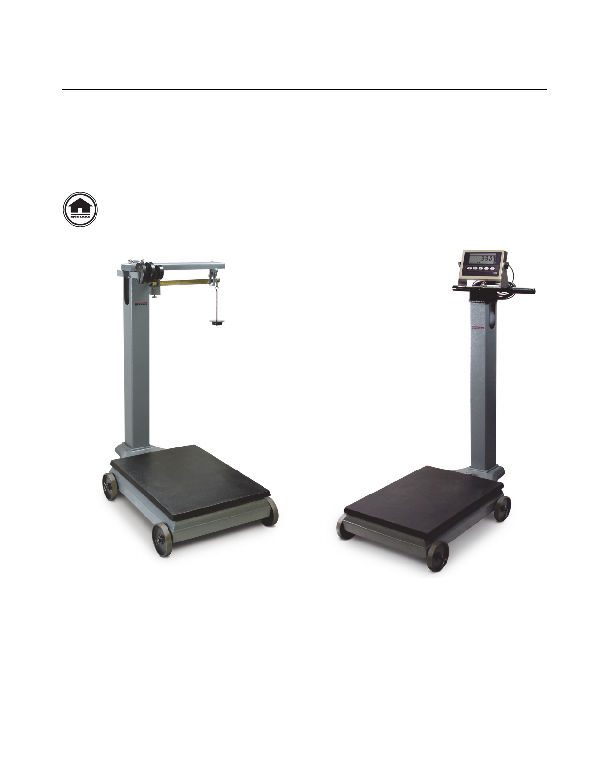
1.0 Introduction
This manual provides assembly and operating instructions for the RL1200 portable beam scale, which is available in both avoirdupois and metric. Please read all instructions carefully before as
This manual covers the installation and setu
• Mechanical assembly of RL1200
• Mechanical to electronic conversion option for the RL1200
Instructions on assembling the mechanical to electron
page 15.
This manual can be viewed and downloaded from the Rice Lake Weighing Systems website at
www.ricelake.com. Rice Lake Weighing Syste
p of two versions of the RL1200:
ic version of the RL1200 can be viewed in Section 4.0 on
ms is an ISO 9001 registered company.
sembling the scale.
Figure 1-1. RL1200 Portable Beam Scale (Mechanical and Electronic Conversion Models shown)
1
Page 6
1.1 Safety
Important
CAUTION
WARNING
DANGER
CAUTION
There are certain precautions that should be taken to prevent personal injury to the user and damage to the scale.
Care should be exercised to assure proper assembly and operation of the RL1200. The RL1200 should be assembled only by a trained scale technician. Untrained personne
l should not attempt to assemble this scale, nor make
any adjustments not specified in these instructions.
1.2 Safety Signals
Safety Signal Definitions:
Indicates an imminently hazardous situation that, if not avoided, will result in death or serious
injury.
Indicates a potentially hazardous situation that,
injury.
Indicates a potentially hazardous situation that,
injury.
Indicates information about procedures that, if not observed, could result in damage to
equipment
.
if not avoided, could result in death or serious
if not avoided, may result in minor or moderate
1.3 Safety Precautions
Do not operate or work on this equipment unless you have read and understand the
instructions in this manual. Failure
in injury or death. Contact any Rice Lake Weighing Systems dealer for replacement manuals.
Proper care is your responsibility.
Before attempting to operate this unit, make sure every individual who operates or works with
this unit has read and understands the following safety information.
instructions carefully.
• Do not drop the scale or subject it to violent shocks.
• For accurate weighing, the scale must be placed on a flat, stable surface.
• Do not transport the scale while someone is standing on it.
• Weight exceeding the maximum capacity (1
• Avoid contact with excessive moisture.
• Do not allow minors (children) or inexpe
rienced persons to operate this scale.
• Do not jump up and down on the scale.
• Do not make alterations or modifications
to the scale.
to follow the instructions or heed the warnings could result
Please follow these
000 lb/ 500 kg) may damage the scale.
2 RL1200
Page 7
2.0 Installation Instructions
2.1 Unpacking the Scale
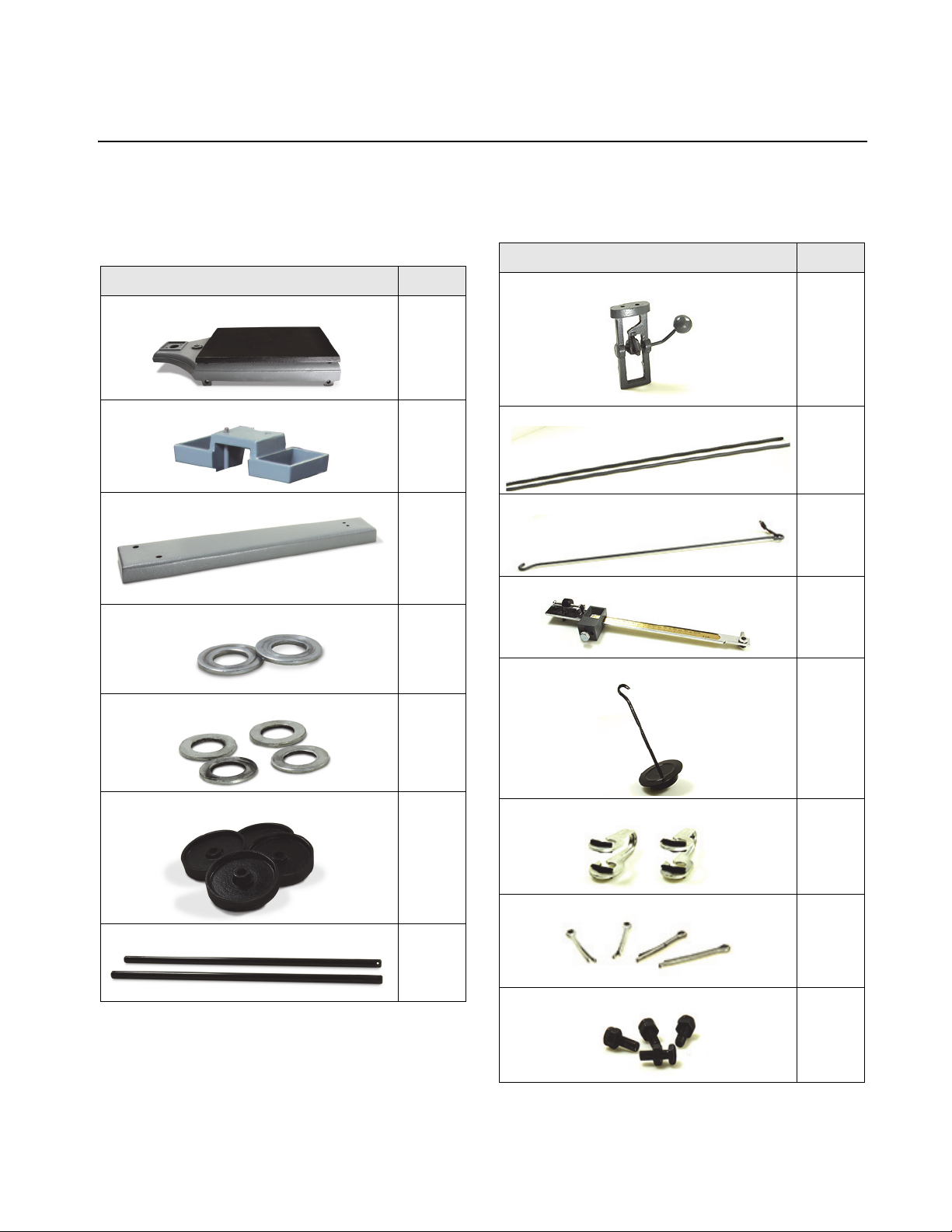
Place the unopened box in an open area that has ample room for unpacking the scale. Remove all parts from the
box. Parts contained in the shipping box include:
Item Description Quantity
Scale Base
Item Description Quantity
1
trig loop assembly 1
Weight rack
Beam cap assembly
Beam cap washers
Axle washers 4
Wheel 4
1
Pillar rod
1
2
Steelyard rod
Beam assembly 1
Counterpoise assembly 1
Loop clamp
2
1
2
Wheel axle
Axle cotter pins
2
Axle locking bolts
4
2
Table 2-1: RL1200 Parts
Table 2-1: RL1200 Parts (Continued)
1
Page 8
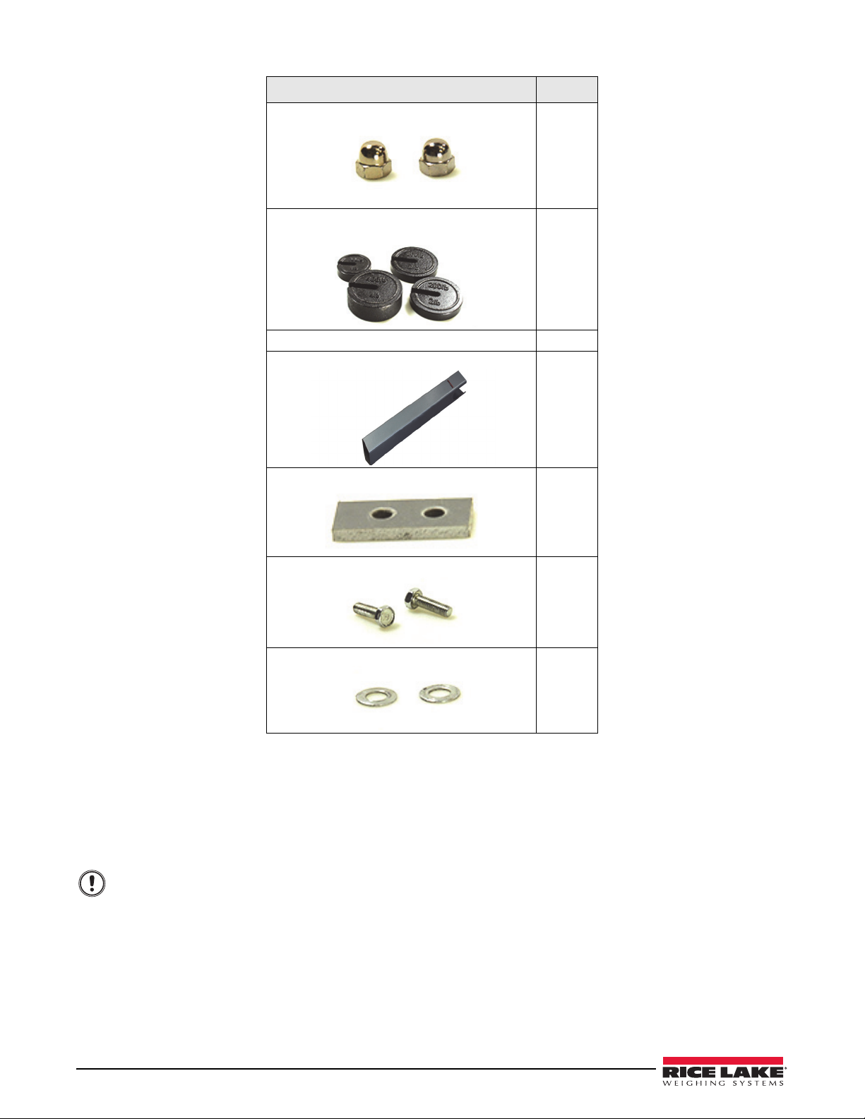
Important
Item Description Quantity
Cap nut for beam cap
Counterpoise weights, 100 lb (1), 200 lb (2),
400 lb (1)
Steel shot for counterpoise 1
Pillar
2
1
Trig loop mounting plate
Trig loop mounting bolts
Trig loop mounting washers
1
2
2
Table 2-1: RL1200 Parts (Continued)
2.2 Repacking
If the RL1200 must be returned for modification or repair, it must be properly packed with sufficient packing materials. Whenever possible, use
Damage caused by improper packaging is not covered by the warranty.
original carton when shipping the scale back.
4 RL1200
Page 9
2.3 Setting Up Your Scale
Note
2.3.1 Assemble Wheels onto Frame
1. It is preferable to set the scale base on a box or other item to keep the scale base up off the floor. Tip the scale
base on its side.
Figure 2-1. Scale Base on its Side
2. Place wheel axles through the holes in the frame.
Figure 2-2. Run Axle Through Scale Base Frame Holes
3. Place the wheels and washers on the axles.
Washers must be placed on the insides of the wheels next to the scale frame.
Wheels must be placed with the extended hub next to the scale frame.
Figure 2-3. Place Washers and Wheels on Each Axle
Setting Up Your Scale 5
Page 10
4. Place the washers and wheels against the frame and insert cotter pins in the holes in the axles. Bend the cotter
pin with pliers to prevent it from slipping out.
Figure 2-4. Run Cotter Pins Through Wheel Axle Holes to Prevent Slipping
5. Finish the wheel assembly by securing axles to frame by securing wheel axle rods with axle locking bolts and
lock nuts. Center the axle and tighten bolt and locknut.
Figure 2-5. Secure Wheel Axle to Frame Using Axle Locking Bolts on Each Wheel
6. Stand the scale base on the floor on its wheels.
Figure 2-6. Place Scale Base on Floor
6 RL1200
Page 11

2.3.2 Attach Pillar to Scale Base
Use the following steps to attach the pillar to the scale base.
1. Screw the pillar rods into the scale base
to place the beam weight rack and beam cap assembly on the pillar.
Figure 2-7. Screw Pillar Rods into Scale Platform
2. Place the pillar over the rods with the label facing the scale platform and the serial model label facing out-
wards as shown in Figure 2-8.
frame approximately three turns. Ensure ample threads are available
Figure 2-8. Place Pillar Over Pillar Rods
Setting Up Your Scale 7
Page 12

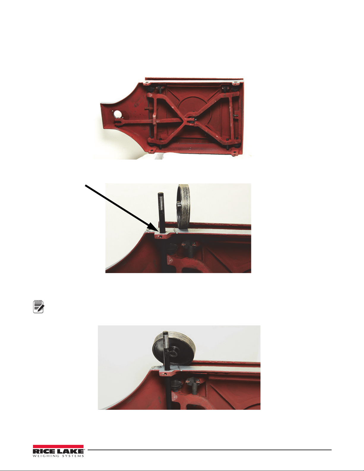
3. To put the connecting steelyard rod into position inside the pillar, raise the long lever under the scale base and
Hook loop onto the
nose iron assembly
under scale base
Important
Hook and
steelyard
hook should
both face as
shown.
hook the lower end of the rod with loop in the nose iron assembly.
Figure 2-9. Attach Hook to Nose Iron Assembly
4. Temporarily hang the steelyard rod on the cutout in the pillar as shown.
8 RL1200
Figure 2-10. Steelyard Hook on Pillar Cutout
If assembling the Mechanical to Electronic version of the RL1200, please proceed to
Chapter 5 on page 14 for further assembly instructions.
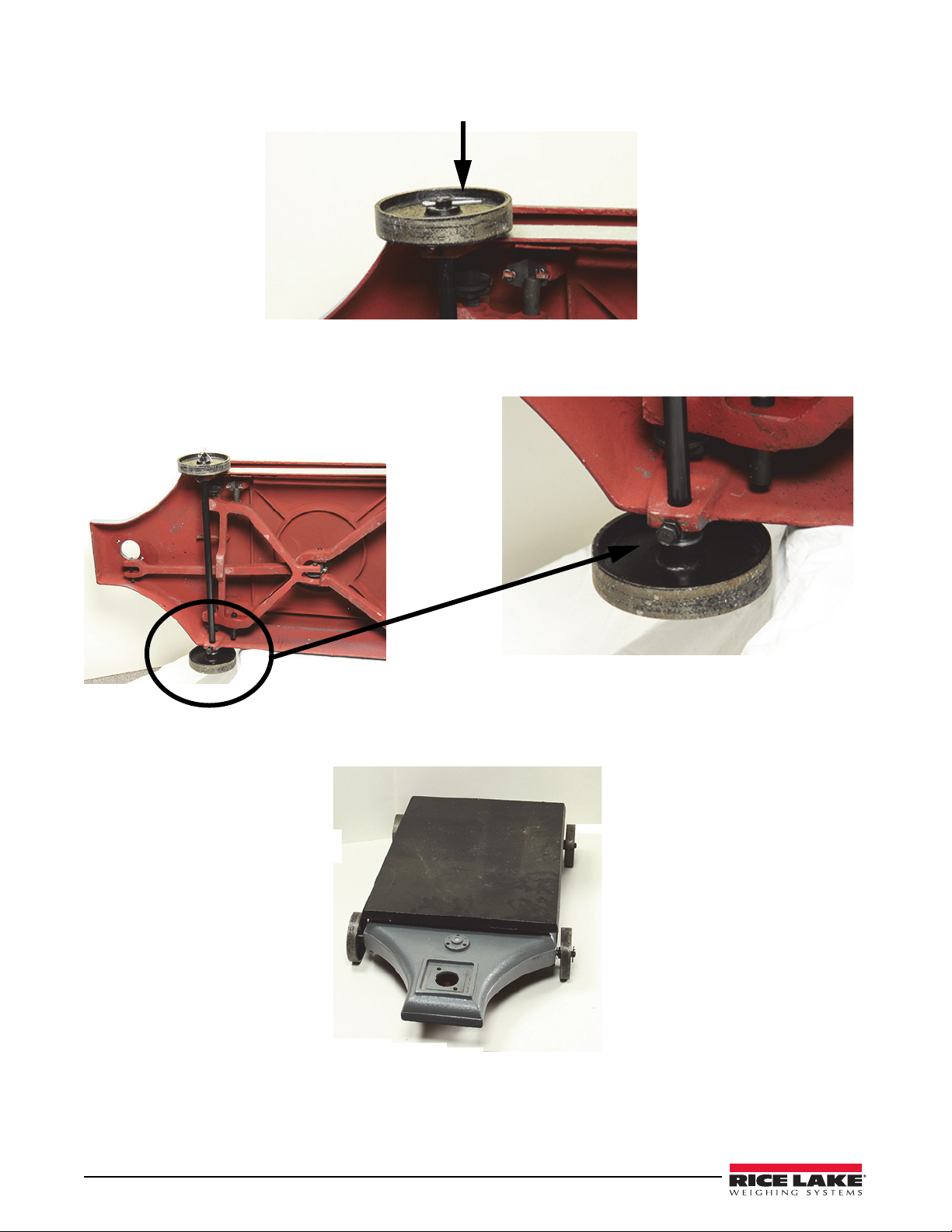
5. Place the weight rack on top of the pillar with the hook facing as
Figure 2-11. Place Weight Rack on Pillar
shown.
Page 13

6. Place the beam cap assembly over the weight rack (facing same direction as hook and steelyard hook) using
Attach loop clamp (as
shown)
Second loop clamp
attaches here facing upwards (also
see Figure 2-14)
Hook the steelyard upper
hook through the lower
loop clamp as shown.
Hook the
upper loop
clamp to the
weight rack
hook (not
shown)
acorn bolts and washers and snug the beam cap assembly.
Figure 2-12. Attach Beam Cap Assembly
7. Attach the two loop clamps onto beam assembly.
8. Take the beam assembly and put the upper end of the steelyard rod through the lower loop clamp on the beam
and hook the upper loop clamp to the hook on the weight rack (not shown).
Figure 2-13. Attach Loop Clamps to Beam Assembly
Figure 2-14. Hook Loop Clamps to Beam Assembly and Weight Rack
Setting Up Your Scale 9
Page 14

2.3.3 Trig Loop Assembly
1. Insert the trig loop assembly to the end of the beam assembly. The ball handle should face towards the scale
base.
2. Place the trig loop mounting plate on top of trig loop a
Figure 2-15. Inserting the Trip Loop Assembly to Beam Assembly and Adding the Trig Loop Mounting Plate
ssembly prior to attaching to beam cap assembly.
3. Use bolts to secure the trig loop assembly to the beam assembly ensuring that trig loop washers are placed
between beam cap assembly and the mounting bolts..
Figure 2-16. Secure Trig Loop Assembly with Bolts
4. Ensure the trig loop assembly is centered horizontally. Adjustments can be made by readjusting the beam
assembly. The beam must not touch or rub the sides to ensure accurate weighments.
5. Once the trig loop assembly is centered,
tighten the beam cap assembly and weight rack to the pillar.
10 RL1200
Page 15

6. Hang the counterpoise assembly from the loop assembly at the tip of the beam.
Figure 2-17. Hanging Counterpoise Assembly
7. Place the scale on a firm, level surface.
8. Set poise(s) at zero and lock. Release the beam lock. A
djust the back balance assembly to bring the beam to a
horizontal position with the tip centered in the trig loop.
9. The zero adjustment screw must be turned clockwise to make th
e beam go up, and counter-clockwise to make
the beam go down.
Figure 2-18. Zero Adjustment Location
10.If the beam cannot be vertically centered, weight may be added or removed from the counterpoise assembly
as necessary by unscrewing the counterpoise weight and adding iron shot into the cavity.
Figure 2-19. Scale Reading on Zero
Setting Up Your Scale 11
Page 16

11.Hang the counterpoise weights on the weight rack until needed.
Figure 2-20. Add Counterpoise Weights Until Needed
12 RL1200
Page 17

3.0 Operation
Use the following steps to safely and correctly operate the RL1200 platform scale.
1. With no load on the scale platform, position the sliding poise at zero. Unlock the trig loop. The beam should
be centered vertically in the trig loop. Adjust the back balance if necessary (see
2. Lock the beam with the trig loop lock and place the object to be weighed on the platform. Add counterpoise
weights to a value slightly less than the estimated object weight. Release the beam lock.
3. The beam should rise to the top of the trig loop. If it does not rise, reduce the amount of counterpoise weights.
Move the poise along the beam until the beam balances with the tip centered in the trig loop.
4. When the beam balances, the object weight is the value indicated by the sliding poise, plus the face value of
the counterpoise weights used. For example, if there are three pounds of counterpoise weights (equivalent to
300 pounds) and the sliding poise(s) on the beam indicates 54.5 pounds, then the object weighs 354.5 pounds.
For a metric example, if there are three 500 gram counterpoise weights (equivalent to 150 kg) and the sliding
poise on the beam indicates 10.2 kg, then the object weighs 160.2 kg.
5. After the weight has been determined, lock the beam. Remove the object from the platform. Note the poise
may be locked at a desired reading by tightening the poise thumb locking screw if a desired weight is needed
repeatedly, such as bagging ingredients.
Figure 1-18 on page 12).
13
Page 18

14 RL1200
Page 19

15
Page 20

16 RL1200
Page 21

17
Page 22

18 RL1200
Page 23

4.0 Mechanical to Electronic Installation Instructions
The conversion from mechanical to electronic weighing is accomplished by a conversion kit. This kit includes:
• IQ plus 390-DC indicator
• Load cell plus load cell cable
• Pre-drilled mounting bracket
• All necessary conversion hardware
The conversion kit requires no special
Prior assembly of the RL1200 through Step 4, Figure 1-10 on page 9 still applies.
4.1 Unpacking The Conversion Kit
Parts contained in the conversion kit include:
tooling or equipment. Assembly requires only ordinary hand tools.
Item Description Quantity
Indicator
Indicator base plate 1
1
Load cell and load cell cable
Eye bolt
Lock washers 6
Bolts
Table 4-1: Conversion Kits Parts List
1
1
4
Unpacking The Conversion Kit 19
Page 24

Item Description Quantity
Locknuts 2
Long bolt
Long bolt washer 1
Table 4-1: Conversion Kits Parts List
1
4.2 Indicator and Load Cell Installation
Use the following steps to attach the indicator and load cell to the RL1200.
1. Take the indicator base plate and lay it on its side.
2. Note the orientation of the load cell. Put
indicator base plate. Thread on the locknut to the bottom of the bolt.
the 3.5" bolt through the long bolt washer and through the top of the
Figure 4-1. Set Indicator Base Plate on Side and Attach Load Cell
3. Screw the eye bolt and locknut into the bottom of the load cell until flush. Tighten the locknut.
Figure 4-2. Screw Eye-Bolt Into Load Cell
20 RL1200
Page 25

4. Place the indicator base plate on pillar aligning the pillar rods through the base plate holes and handles facing
Pillar rods
Attach the steelyard hook
through eye-bolt
the back of the scale.
Figure 4-3. Mount Base Plate to Pillar and Attach Steelyard Hook
5. Hook the steelyard hook through the eye-bolt as shown in Figure 4-3.
6. Push the load cell cable inside pillar leaving
enough slack inside pillar and draw the cable end up through hole
in the base plate.
7. Tighten the indicator base plate to the pillar by using lock washers and acorn nuts as shown in Figure 4-4.
8. Run load cell cable through the tilt stand on the
Figure 4-4. Run Load Cell Cable Through Base Plate and Tighten Base Plate to Pillar
indicator.
Figure 4-5. Run Load Cell Cable Through Bottom of Indicator Tilt Stand
Indicator and Load Cell Installation 21
Page 26

9. Set indicator on base plate and secure with four bolts and lock washers.
Figure 4-6. Secure Indicator to Base Plate
10.Wrap excess cable around cable hooks on handle.
Figure 4-7. Store Excess Load Cell Cable
11.Connect cable from the load cell through the load cell cable cord grip to connector J1 as shown in Tab le 4-2.
J1 Pin Function
1
2
3
4
5
6
7
For 6-wire load cell connections, remove jumpers JP1
and JP2
Table 4-2: J1 Pin Assignments
+SIG
-SIG
+SENSE
-SENSE
SHIELD
+EXC
-EXC
22 RL1200
Page 27

12.If using a 6-wire load cell cable (with sense wires), remove jumpers JP1 and JP2 before reinstalling connector
R12
C34
C33
D3
D4
RN1
C40
C38
C36
C39
C35
R23
C72
C73
C71
C74
C78
C76
R27
R28
C81
C83
R24
R25
R31
D5
F1
C80
EMI1
R46
R45
R44
R40
R39
R38
R37
C92
C91
C90
R34
R33
R43
C84
C85
U15
C77
VR2
D1
R2
C31
C32
R1
C1
L2
C28
U1
VR1
L1
C13
C6
R7
C10
C9
R26 C79
C75
U6
C14
R32
R29
C82
C2
XT1
C4
C8
C7
C3
C5
R6
R5
R3
R4
C41
R15
R14
C37
C42
Q1
C11
C12
R30
C86
C87
C15
U12
U10
U7
U11
R8
C17
C18
C19
R9
C16
C20
C27
U9
C88
C89
VR4
U8
R49
R50
C95
R48
R42
R41
C94
C93
R35
R36
R47
RICE LAKE WEIGHING SYSTEMS
1
RESET
AGND
DGND
+SIG
–SIG
+SENSE
–SENSE
SHIELD
+EXC
–EXC
1
2
3
4
5
6
7
LOAD CELL
CONNECTOR
J1
JP2
JP1
D2
J5
Keypad Connector
1
J4
J2
TxD
GND
RxD
1
2
3
SERIAL PORT
1
J3
Battery
Input
AC
Adapter
Input
1
J6
To Setup
Switch
A/D Converter
GND
GND
1
J7
VR3
U4
Microcontroller
U5
FLASH RAM
U2
U3
Display Drivers
R11C29R13
C30
RN2
+
+
+
C26
C23
C25
R10
C21
C22
C24
+
J1 (see
Figure 4-8). For 4-wire installation, leave jumpers JP1 and JP2 on.
Figure 4-8. IQ Plus 390-DC Indicator Board
4.3 Final Adjustment, Calibration and Troubleshooting
Final adjustment, calibration and troubleshooting of the IQ Plus 390-DC indicator can be found in the IQ Plus
390-DC Installation Manual, PN 48820.
Final Adjustment, Calibration and Troubleshooting 23
Page 28

5.0 Appendix
Check frequently for correct balance with no load on the platform, the poise(s) set at zero, and no counterpoise
weights applied.
• Keep the beam locked until
• Do not overload the scale.
• Do not oil any part of the scale. Keep the scale as clean and dry as possible at all times.
• Make sure the operation of the scale is checked at regular inte
5.1 Specifications
Construction Cast iron platform, base and levers
Weigh beam Single beam, die-cast aluminum, dual sided
Poise Steel locking screw provided
Pivots and bearings Precision machined hardened tool steel
Counterpoise weights 100 lb / 45 kg (1), 200 lb / 90 kg (2), 400 lb / 181 kg (1)
Overall dimensions 36.13 L (917.7 mm)
Platform dimensions 18 x 24" (457.2 x 609.6 mm)
Platform deck height 6" without wheels attached, 8" wi
Capacity 1000 lb / 500 kg
Approximate shipping weight 230 lb / 104 kg
Warranty 1 year limited
the load has been applied to the platform.
rvals.
beam graduation in .5 lb or
.2 kg increments
25.25 W (641.35 mm)
43 H (1092.2 mm)
th the wheels attached
For More Information
Website
• http://www.ricelake.com
Contact Information
Hours of Operation
Knowledgeable customer service representatives are available 6:30 a.m. - 6:30 p.m. Monday through Friday and 8
a.m. to 12 noon on Saturday. (CST)
Telephone
• Sales/Technical Support 800-472-6703
• Canadian and Mexican Customers 800-321-6703
• International 715-234-9171
Fax
• Fax Number 715-234-6967
Email
• U.S. sales and product information at prodinfo@ricelake.com
• International (non-U.S.) sales and produc
Mailing Address
t information at intlsales@ricelake.com
Rice Lake Weighing Systems
230 West Coleman Street
Rice Lake, WI 54868 USA
24 RL1200
Page 29

RL1200 Portable Beam Scale Limited Warranty
Rice Lake Weighing Systems (RLWS) warrants that all RLWS equipment and systems properly installed by a Distributor or Original Equipment Manufacturer (OEM) will operate per written specifications as confirmed by the
Distributor/OEM and accepted by RLWS. All systems and components are warranted against defects in materials
and workmanship for one year.
RLWS warrants that the equipment sold hereunder will conform to the current written specifications authorized by
RLWS. RLWS warrants the equipment against faulty workmanship and defective materials. If any equipment fails
to conform to these warranties, RLWS will, at its option, repair or replace such goods returned within the warranty
period subject to the following conditions:
• Upon discovery by Buyer of such nonconformity, RLWS will be given prompt written notice with a
detailed explanation of the alleged deficiencies.
• Individual electronic components returned to RLWS for warranty purposes must be packaged to prevent
electrostatic discharge (ESD) damage in shipment. Packaging requirements are listed in a publication, Pro
tecting Your Components From Static Damage in Shipment, available from RLWS Equipment Return
Department.
• Examination of such equipment by RLWS confirms that the nonconformity actually exists, and was not
caused by accident, misuse, neglect, alteration, improper installation, improper repair or improper testing;
RLWS shall be the sole judge of all alleged non-conformities.
• Such equipment has not been modified, altered, or changed by any person other than RLWS or its duly
authorized repair agents.
• RLWS will have a reasonable time to repair or replace the defective equipment. Buyer is responsible for
shipping charges both ways.
• In no event will RLWS be responsible for travel time or on-location repairs, including assembly or disas-
sembly of equipment, nor will RLWS be liable for the cost of any repairs made by others.
THESE WARRANTIES EXCLUDE ALL OTHER WARRANTIES, EXPRESSED OR IMPLIED, INCLUDING WITHOUT LIM-
ITATION WARRANTIES OF MERCHANTABILITY OR FITNESS FOR A PARTICULAR PURPOSE. NEITHER RLWS NOR
DISTRIBUTOR WILL, IN ANY EVENT, BE LIABLE FOR INCIDENTAL OR CONSEQUENTIAL DAMAGES.
RLWS AND BUYER AGREE THAT RLWS’S SOLE AND EXCLUSIVE LIABILITY HEREUNDER IS LIMITED TO REPAIR
OR REPLACEMENT OF SUCH GOODS. IN ACCEPTING THIS WARRANTY, THE BUYER WAIVES ANY AND ALL OTHER
CLAIMS TO WARRANTY.
SHOULD THE SELLER BE OTHER THAN RLWS, THE BUYER AGREES TO LOOK ONLY TO THE SELLER FOR WAR-
RANTY CLAIMS.
NO TERMS, CONDITIONS, UNDERSTANDING, OR AGREEMENTS PURPORTING TO MODIFY THE TERMS OF THIS
WARRANTY SHALL HAVE ANY LEGAL EFFECT UNLESS MADE IN WRITING AND SIGNED BY A CORPORATE OFFI-
CER OF RLWS AND THE BUYER.
-
© 2014 Rice Lake Weighing Systems, Inc. Rice Lake, WI USA. All Rights Reserved.
RICE LAKE WEIGHING SYSTEMS • 230 WEST COLEMAN STREET • RICE LAKE, WISCONSIN 54868 • USA
Specifications 25
Page 30

26 RL1200
Page 31

Page 32

230 W. Coleman St. • Rice Lake, WI 54868 • USA
U.S. 800-472-6703 • Canada/Mexico 800-321-6703 • International 715-234-9171 • Europe +31 (0)26 472 1319
www.ricelake.com www.ricelake.mx www.ricelake.eu www.ricelake.co.in m.ricelake.com
© Rice Lake Weighing Systems 11/19/14 PN 157986
 Loading...