

Page 1
Ethernet 802.11b
For Use With MSI-9850, MSI-9300 and MSI-6260CS
Operator’s Manual
161444
Page 2

Page 3

Technical training seminars are available through Rice Lake Weighing Systems.
Course descriptions and dates can be viewed at www.ricelake.com/training
or obtained by calling 715-234-9171 and asking for the training department.
Contents
1.0 Introduction......................................................................................................................................1
2.0 Quick Start .......................................................................................................................................1
3.0 Ethernet 10/100 Base-T Connection ................................................................................................2
3.1 Cabling . . . . . . . . . . . . . . . . . . . . . . . . . . . . . . . . . . . . . . . . . . . . . . . . . . . . . . . . . . . . . . . . . . . . . . . . . 2
4.0 802.11b Connection .........................................................................................................................2
5.0 Configuring Network Settings .........................................................................................................3
5.1 MSI Scale Discovery Utility. . . . . . . . . . . . . . . . . . . . . . . . . . . . . . . . . . . . . . . . . . . . . . . . . . . . . . . . . . . 3
5.2 Web Interface . . . . . . . . . . . . . . . . . . . . . . . . . . . . . . . . . . . . . . . . . . . . . . . . . . . . . . . . . . . . . . . . . . . . 5
5.2.1 IP Settings . . . . . . . . . . . . . . . . . . . . . . . . . . . . . . . . . . . . . . . . . . . . . . . . . . . . . . . . . . . . . . . . . . . . . . . . .6
5.2.2 Wireless Settings . . . . . . . . . . . . . . . . . . . . . . . . . . . . . . . . . . . . . . . . . . . . . . . . . . . . . . . . . . . . . . . . . . . .6
6.0 Installation without Supporting Network Infrastructure .................................................................8
7.0 Next Steps........................................................................................................................................9
8.0 Appendix A – Using Hyper Terminal ..............................................................................................10
9.0 Appendix B – Adding direct.msiscales.com to Security...............................................................11
10.0 Appendix C – FAQ...........................................................................................................................12
11.0 Appendix D – Wireless Troubleshooting .......................................................................................13
12.0 Glossary .........................................................................................................................................14
© Rice Lake Weighing Systems. All rights reserved. Printed in the United States of America.
Rice Lake Weighing Systems is an ISO 9001 registered company.
Specifications subject to change without notice.
March 25, 2014
Contents i
Page 4

ii Ethernet Option Operator’s Manual
Rice Lake continually offers web-based video training on a growing selection
of product-related topics at no cost. Visit www.ricelake.com/webinars.
Page 5
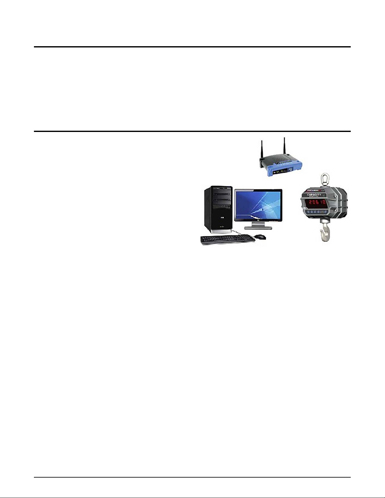
1.0 Introduction
Figure 2-1. Quick Start ‐ Connecting to the Network
MSI-9300 Shown
The Ethernet option provides the ability to connect a crane scale directly to a PC, corporate network or the Internet.
The Ethernet option is available as either wired
Communication with the scale is accomplish
communications with RS-232.
10/100Base-T or wireless 802.11b network interface.
ed with simple TCP protocol, bypassing th e more complex serial
2.0 Quick Start
1. Connect to the network with an unsecured 802.11b
access point.
2. Access the MSI Scale Discovery Utility.
3. Scan the network for the crane
4. Configure IP settings (see th
information is unknown).
5. Open the web interface and configure
security settings as necessary.
6. Reboot the Ethernet interface to apply settings (allow
on
e minute for reboot).
7. Scan the network to confirm settings have
8. Open a connection from any TCP client (Windows
Hyper-Terminal, telnet) to confirm communications.
scale.
e network administrator if
network and
applied.
®
Introduction 1
Page 6
3.0 Ethernet 10/100 Base-T Connection
1
2
A
B
12
28
C
3
4
D
E
F
G
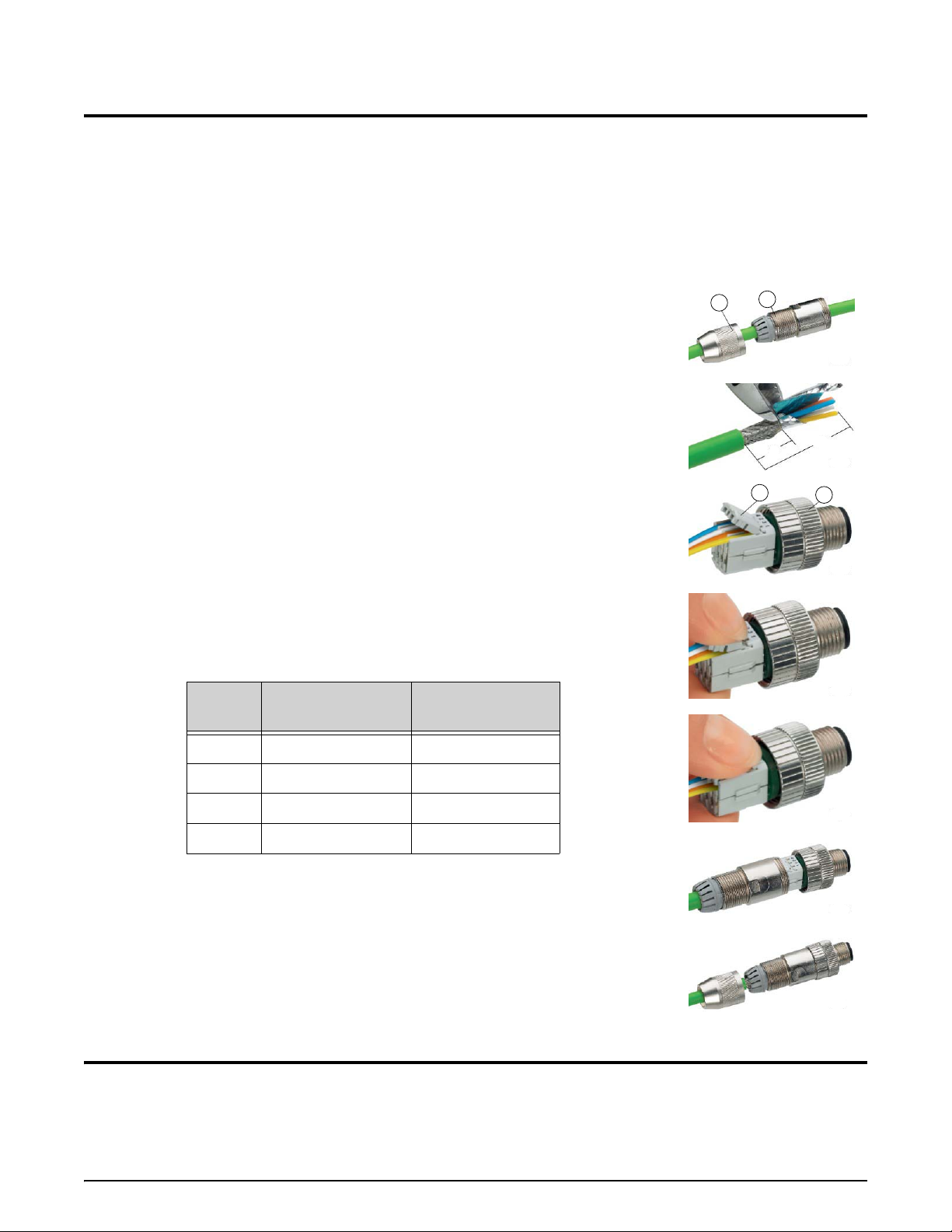
Figure 3-1. Cable Assembly
The Ethernet interface defaults to use Dynamic Host Configuration Protocol (DHCP) for obtaining an IP address. It
is not necessary to be running a DCHP server to discover the scale device on your network. The MSI Scale
Discovery Utility uses multi-cast IP to discover and configure the device.
Once the device has an IP address, further configuration c
The Ethernet connection can be made to your network via a hub
Ethernet port using a crossover Ethernet cable. For details, please reference your networking hardware manual, or
contact your network administrator.
3.1 Cabling
MSI provides a field-installable mating connector (MSI#13587) that allows
customers to interface with their own Ethernet cabling. The connector accepts cables
up to 8mm.
Cable Assembly
See Figure 3-1
1. Slide the pressure nut (item 1) and the ho
2. Strip the cable sheath over a length of ap
shield to a length of approximately 12mm (View B).
3. See Table 3-1 for the core assignment.
4. Guide the individual cores fully into the m
correct chambers and only one core per chamber (View C).
5. Contact the cores by pressing the termination b
to Views D and E. The termination blocks engage at the end stop.
6. Pull the housing (item 2) out as far as the plug insert (item 3) and hold it tight
wh
ile you screw the plug insert onto it (View F).
7. Push the pressure nut (item 1) on the housing. Tighten the
(V iew G).
using (item 2) over the cable. (View A)
proximately 28mm. Trim the braided
arked chambers. Make sure to use the
an be done via the web page interface if necessary.
or switch, or can go directly to your computers
locks (item 4) together according
pressure nut firmly
Pin
1 White/Orange TD+
2 Orange TD-
3 White/Green RD+
4 Green RD-
TIA 568 B
Color Function
Table 3-1. Core Assignment
4.0 802.11b Connection
The 802.11b interface defaults to an unsecured connection. This allows the device to connect to any unsecured
network for configuration. Once connected to an unsecured network, any secure network settings can be applied and
the unit will operate the secure network from that point on.
Information on configuring the wireless security settin
to Section 11 o n page 13.
gs can be found in the web interface, wireless settings. Refer
2 Ethernet Option Operator’s Manual
Page 7

5.0 Configuring Network Settings
Note
Note
Network settings can be configured from the MSI Scale Discovery Utility , or by opening a web pag e and pointing it
at the scale device address. The network configuration is specific to every network. Please consult the network
administrator for this information.
5.1 MSI Scale Discovery Utility
Direct.msiscales.com may need to be added to the security on the computer for the Scale Discovery Utility to
run. See Section 9 on page 11..
The Scale Discovery Utility can be accessed from the MSI Website
program requires
Java 6.0 or greater to run. The Scale Discovery Utility uses UDP port 2362 and a multi-cast IP
address of 224.0.5.128. These will need to be enabled on the
under Products/Software Applications
. The
firewall for the Scale Discovery Utility to work
(typically enabled by default).
The program is loaded from the web page via Java Web Start technology
. This ensures whenever the program is
started, the latest version is being used.
Figure 5-1. MSI Scale Discovery Utility
Select Scan Network for the scale. The scan should take five seconds, and when complete will show a list of the
scales found.
When the scale first turns on, the network interface should be allowed one minute to boot up and acquire an
address.
To view information about the Ethernet interface, select Device Information.
Figure 5-2. Scale Discovery Utility - Device Information
Configuring Network Settings 3
Page 8

To configure the device, use the Configure button to open a dialog where it can adjust the network settings to use
Note
DHCP or manually enter the IP address information.
Figure 5-3. Scale Discovery Utility - Configure
After entering the desired network configuration, select OK to send the configuration to the scale. After sending the
configuration, the settings will have to be applied with the
After the scale Ethernet interface settings have been set, rescan
Then use the
Chat button to open a dialog that demonstrates simple communication with the scale .
Reboot Device button.
the network to find the device with the new settings.
Figure 5-4. Scale Discovery Utility - Chat
The transmit buttons are quick links to sending a few of the mo st commo n host commands available.
•
@W1– requests the current weight from the scale
•
@D1– requests the
•
@T1– requests the current time from the scale
@E – prints the programmed end of line string (defaults to carriage return, line feed).
•
•Semicolon (;) is
If the other host commands do not get responses, use the semicolon command to reset the scale parser.
current date from the scale
a special command the instructs the scale to res et its co mmand pars er.
The Scale Discovery Utility provides a quick link to Open Web Interface to the scale. The following section details
the web interface.
4 Ethernet Option Operator’s Manual
Page 9

5.2 Web Interface
The web interface can be accessed after a device has already been configured. Navigate the web browser to the URL
http://{ipaddress}/, the first page will be the login screen. Login with:
Username –
Password – 0199
msi
Figure 5-5. Web Interface Login
After logging in the screen in Figure 5-6 will be shown.
Figure 5-6. Web Interface Homepage
Configuring Network Settings 5
Page 10

5.2.1 IP Settings
T o configure the network interface, select Network from the menu on the left to see the following page.
Figure 5-7. Web Interface Network Configuration
Enter the network settings and select Apply when complete. The device will prompt to reboot. After rebooting, the
new settings will take effect.
5.2.2 Wireless Settings
Wireless settings are configured on three pages tha t are accessible via the web inte rface.
6 Ethernet Option Operator’s Manual
Figure 5-8. Wireless LAN Settings
Page 11

Enter the Network name and Channel for the network the scale will be connected to.
Wireless Security Settings are configured via the web interface. The following is a summary of the supported
wireless security capabilities.
• WEP (Wired Equivalent Privacy)
- 64/128-bit encryption (RC4)
•
WPA/WPA2/802.11i
- Strong SSL 3.0/TLS 1.0 based enc rypt ion
DES (56-bit), 3DES (168-bit), AES (128/256-bit)
- 128-bit TKIP/CCMP encryption
-802.1x
- EAP authentication
LEAP (WEP only), PEAP, TTLS, TLS
GTC, MD5, OTP, PAP, CHAP, MSCHAP, MSCHAPv2, TTLS-MSCHAPv2
- Enterprise and Pre-Shared Key (PSK) mode
Wireless 802.1x Authentication Settings – After the wireless interface is configured, IP settings can be
reconfigured as above with the MSI Scale Discovery Utility.
Configuring Network Settings 7
Page 12

6.0 Installation without Supporting Network Infrastructure
Note
In some situations a network infrastructure may not be available. Figure 6-1 is an illustration of a scale
needing to communicate to a standard desktop computer running Microsoft Windows Operating System.
The access point (or switch) is configured to bridge mode and does not provide DHCP services.
Figure 6-1. Supporting Network Infrastructure
This configuration may require additional support software to configure the scale network interfaces. The
following procedure helps with this type of system.
1. Configure MS Windows as DHCP server
- Install the program
- Edit the configuration file for your needs. The following is a basic configuration:
Open DHCP Server (http://dhcpserver.sourceforge.net/)
[LISTEN_ON]
192.168.0.1
[RANGE_SET]
DHCPRange=192.168.0.10-192.168.0.254
[GLOBAL_OPTIONS]
SubNetMask=255.255.255.0
- Set your computer network interface to static IP (example 192.168.0.1).
- Temporarily disable any Firewall running on your computer.
- Start the program as a Windows S
ervice (or standalone depending on your installation)
2. Cycle power on the scale device.
3. Run the Scale Discovery Utility as described previously
Running the Open DHCP Server on your computer while attached to a network with supporting services can
cause errors. Be sure to disable (or un-install) the program when not needed. For
department.
.
details consult the IT
8 Ethernet Option Operator’s Manual
Page 13

The following is an example session running Open DHCP Server, local computer network interface
configuration and the Scale Discovery Utility.
Figure 6-2. Open DHCP Server
7.0 Next Steps
Now that it has been configured on the network, there is access to the scale for host communications via port 2101.
The host commands provide the ability to read all aspects of weight data ranging from Current, Gross, Net, Tare
weight to Total weight, and statistics. Additionally, the host command language provides the ability to configure
settings in the crane scale.
Complete details about host communications can be found in the Cran e S c al e man ual.
Next Steps 9
Page 14

8.0 Appendix A – Using Hyper Terminal
Hyper Terminal is a communications program that is commonly available on Microsoft® Windows operating
systems. This program can be used to connect to an Ethernet interface for communications and testing.
1. Start Hyper T erminal.
2. Enter a name for the connection and
select an Icon.
Figure 8-1. Connection Description
3. Configure the connection to use TCP/IP.
4. Enter the device address and port number 2101.
5. The connection is now established. Use
string if the crane scale is configured so.
the host commands to talk to the scale or observe the continuous print
Figure 8-2. Hyper Terminal Connection
6. To end the session, close Hyper Terminal. The program will prompt to save the co nnection, which is
recommended.
10 Ethernet Option Operator’s Manual
Page 15

9.0 Appendix B – Adding direct.msiscales.com to Security
Direct.msiscales.com may need to be added to the security on the computer in order for the Scale Discovery Utility
to be allowed to run.
1. In Windows 7, go to Control Panel
2. Select Programs (for category view)
3. Select Java to open the Java Control Panel
4. Select the Security tab
5. Click the
6. Add
Edit Site List… button
http://direct.msiscales.com, see Figure 9-1.
Figure 9-1. Add MSI Site to Security
Appendix B – Adding direct.msiscales.com to Security 11
Page 16

10.0 Appendix C – FAQ
Question
Answer
Question
Answer
Question
Answer
Question
Answer
Question
Answer
Can I write my own program to talk to the scale and record weight information?
Yes, the Cr
data and scale configuration. For full details see the Crane Scale manual.
Can I connect multiple computers to the scale at once via the Ethernet interface?
No, the Cr
Can I access a web page to view the scale weight?
No, the Cr
network settings only.
What if Scale Discovery Utility does not find the C
network.
There may be some network fir
Crane Scale that
network firewall settings to ensure UDP port 2362 and multicast IP address 224.0.5.128 are not
being blocked.
What if I get an error dialog message in the
Only one active connection to the scale Chat or host interface can be active at a time. Likely
the
re is another program running (perhaps on another computer) that is already talking to the
scale.
ane Scale provides a host communication language to access all aspects of weight
ane Scale supports a single TCP/IP connection at a time.
ane Scale web page interface provides a secondary means of configuring the
rane Scale even though it is connected to the
ewall settings between the Scale Discovery Utility and the
are preventing communications. Have the network administrator check the
Scale Discovery Utility when I press Chat.
Question
Answer
Can I use an MSI-97
No, the 802.11b interface of the crane scale replaces the standard 2.4GHz radio in the
CellScale product family. These radios are not compatible with each other.
50 hand-held or MSI-9850 meter with my 802.11b equipped crane scale?
12 Ethernet Option Operator’s Manual
Page 17

11.0 Appendix D – Wireless Troubleshooting
The main challenge is getting the 802.11b equipped Crane Scale to associate with a Wireless Access Point (WAP).
Once this is accomplished, the Crane Scale can be further configured by using the Scale Discovery Utility.
The settings below are the default settings that the Crane Scale will attempt to look for in an access point. Once the
Crane Scale has associated these settings, they can be changed, provided they are changed on the Crane Scale AND
the access point. At this point, encryption and authentication can be set up.
Access Point Settings (Case Sensitive):
SSID: Connect
Authentication: none (i.e. open) Encryption : none
Channel: Auto (1, 6, 11 preferred)
Mode: Infrastructure (as opposed to Ad Hoc) DHCP server: enabled
The Crane Scale by default will look for an access point with an SSID of “Connect.” If it can't find “Conn ect” it will
then look for an Ad Hoc network with an SSID of “Connect.” If that fails it will then associate with the strongest
unencrypted access point signal regardless of SSID. If there are more than one access points, the Crane Scale will
attempt to associate with the SSID of “Connect,” regardless of signal strength. The Crane Scale needs an access
point without authentication or encryption. It will not be able to associate if either of them are enabled. It can
associate with any channel, but 1, 6, or 11 are
look for an access point in Infrastructure mode. It will come up in “BSS_Join” mode.
Once the Crane Scale has successfully associated with the access point, assuming that the module has not been
assigned a static IP address, it will attempt to acquire a dynamic IP address from any available
network.
preferred (assuming North America). The Crane Scale by default will
DHCP server on the
OTHER TROUBLESHOOTING TIPS
• Make sure the AP is running in mixed or “B mode” (802.11b). If it is running in "G Mode" (802.11G) only the
Crane Scale module will not be able to associate with it as it can only do “B mode” (11 Mbps).
• If problems continue, then try to force the Crane Scale to associate with the desired access point. Remove the
antenna from the Crane Scale and move it within a few inches of the desired access point. Check the above
settings on the access point. If have any other access points in the area might want to power them off.
• Make sure the access point is not blocking multi-cast IP traffic. The Scale Discovery Utility uses multi-cast IP to
find and configure scale network settings.
• Make sure the access point being used has the newest firmware loaded onto it. In rare circumstances, errors in
the access point’ s firmw are can impede communications.
Appendix D – Wireless Troubleshooting 13
Page 18

12.0 Glossary
802.3
The IEEE standard for wired Ethernet.
802.11
The IEEE standard for wireless Local Area Networks.
DHCP
See Dynamic Host Configuration Protocol.
Dynamic Host Configuration Protocol (DHCP)
An Internet protocol for automating the configuration of computers that use TCP/IP. DHCP can be used to
automatically assign IP addresses, to deliver TCP/IP stack configuration parameters such as the subnet mask
and default router, and to provide o ther configuration information.
Hyper-Text Transfer Protocol (HTTP)
An application protocol in the TCP/IP suite that defines the rules for transferring files (text, graphic images,
sound, video, and other multimedia files) on the W orld Wide Web (WWW).
MAC address
A unique network identifier. All network devices are required to have their own unique MAC address. The
MAC address is on a sticker on the Digi device server. The number is displayed as 12 hexadecimal digits,
usually starting with 00:40:9D.
Multi-cast IP
A method of forwarding IP datagrams to a group of interested receivers.
TCP
See Transmission Control Protocol.
Transmission Control Protocol (TCP)
A set of rules (protocol) used along with the Internet Protocol (IP) to send data in the form of message units
between computers over the Internet. While IP handles the actual delivery of the data, TCP handles keeping
track of the individual units of data (called packets) that a message is divided into for efficient routing through
the Internet.
For example, when an HTML file is sent to from a Web server, the Transmission Control Protocol (TCP)
program layer in that server divides the file into one or more packets, numbers the packets, and then forwards
them individually to the IP program layer. Although each packet
get routed differently through the network. At the other end (the client program in the computer), TCP
reassembles the individual packets and waits until they have arrived to forward them as a single file.
TCP is known as a connection-oriented protocol, which means that a connection is established and maintained
until such time as the message or messa ges to be ex changed by the application programs at each end have been
exchanged. TCP is responsible for ensuring that a message is divided into the packets that IP manages and for
reassembling the packets back into the complete message at the other end. In the Open Systems Interconnection
(OSI) communication model, TCP is in layer 4, the Transport Layer.
has the same destination IP address, it may
14 Ethernet Option Operator’s Manual
Page 19

Page 20

A RICE LAKE WEIGHING SYSTEMS COMPANY
Measurement Systems
International
TM
14240 Interurban Avenue South Suite 200 Ɣ Seattle, WA 98168-4661 Ɣ USA
Phone: 206-433-0199 Ɣ Fax: 206-244-8470
©
Rice Lake Weighing Systems
www.ricelake.com www.ricelake.mx www.ricelake.eu www.ricelake.co.in m.ricelake.com
www.msiscales.com
© Rice Lake Weighing Systems 03/2014 PN 161444
 Loading...