

Page 1
Operator’s Manual
Page 2

Page 3

Copyright Information:
CG Triumvirate is a trademark of Agfa Corporation.
CG Times based upon Times New Roman under license from the Monotype Corporation.
Windows is a registered trademark of the Microsoft Corporation.
All other brand and product names are trademarks, service marks, registered trademarks, or
registered service marks of their respective companies.
Firmware (Software) Agreement
The enclosed Firmware (Software) resident in the Printer is owned by Licensor or its suppliers and
is licensed for used only on a single printer in the user’s Trade or Business. The User agrees not
to, and not to authorize or permit any other person or party to, duplicate or copy the Firmware or
the information contained in the non-volatile or programmable memory. The firmware (Software)
is protected by applicable copyright laws and Licensor retains all rights not expressly granted. In
no event will Licensor or its suppliers be liable for any damages or loss, including direct, incidental,
economic, special, or consequential damages, arising out of the use or inability to use the
Firmware (Software).
Information in this document is subject to change without notice and does not represent a
commitment on the part of Datamax Barcode Products Corporation. No part of this manual may be
reproduced or transmitted in any form or by any means, for any purpose other than the
purchaser's personal use, without the expressed written permission of Datamax Corporation.
All rights reserved. Printed in the United States of America.
© Copyright 2007 by Datamax Corporation
Part Number: 88-2340-01
Revision: B
Important Safety Instructions
This printer has been carefully designed to provide many years of safe, reliable performance. As
with all types of electrical equipment, however, there are a few basic precautions you should take
to avoid hurting yourself or damaging the device:
• Carefully read the installation and operating instructions provided with your printer.
• Read and follow all warning instruction labels on the printer.
• Place the printer on a flat, firm, solid surface.
• To protect your printer from overheating, make sure all openings on the printer are not
blocked.
• Do not place the printer on or near a heat source.
• Do not use your printer near water, or spill liquid into it.
• Be certain that your power source matches the rating listed on your printer. If you are unsure,
check with your dealer or with your local power company.
• Do not place the power cord where it will be walked on. If the power cord becomes damaged
or frayed replace it immediately.
• Do not insert anything into the ventilation slots or openings on the printer.
• Only qualified, trained service technicians should attempt to repair your printer.
Page 4
Agency Compliance and Approvals:
UL60950-1; 1
CSA C22.2 No. 60950-1-03 1
EN60950-1 (2001) 1
IEC60950-1 (2001) 1
st
Edition, 2006-07-07
st
Edition
st
Edition
st
Edition; 2006-07
As an Energy Star Partner, the manufacturer has determined that this product meets the
Energy Star guidelines for energy efficiency.
The manufacturer declares under sole responsibility that this product conforms to the following
standards or other normative documents:
EMC: EN 55022 (1993) Class B
EN 50024 (1998)
Safety: This product complies with the requirements of EN 60950-1, 1
st
Edition
Gost-R
GB4943-2001, GB9254-1998, GB17625-1-2003
Page 5

s
t
n
e
t
n
o
C
C
C
1 Getting Started
1.1 Introduction.......................................................................1
1.2 Unpacking .........................................................................1
2 Printer Setup
2.1
2.2 Loading Media.................................................................... 5
2.3 Media Sensor Adjustment ....................................................7
2.4 Loading Ribbon ..................................................................8
3 Printer Operation
3.1
3.2 Front Panel (Display Printers)...............................................15
3.3 Windows Driver..................................................................16
3.4 Printer Configuration Utility (DMXConfig) ...............................18
3.5 Media Calibration................................................................19
4 Menu System
4.1
4.2 The User Menu...................................................................24
4.3 The Advanced Menu............................................................24
4.4 The Test Menu ...................................................................25
4.5 Menu Details......................................................................25
n
o
n
o
Printer Connections.............................................................3
Front Panel (Non-Display Printers) ........................................13
Menu System (Display Printers Only).....................................23
t
t
e
e
n
n
t
t
s
s
i
Page 6

5 Maintenance and Adjustments
Cleaning Intervals...............................................................45
5.1
5.2 Cleaning the Printhead ........................................................46
5.3 Media Width Adjustment......................................................48
5.4 Printhead Burn Line Adjustment............................................49
5.5 Printhead Pressure Adjustment.............................................50
5.6 Printhead Replacement........................................................51
5.7 Darkness Adjustment..........................................................52
5.8 Resetting the Printer ...........................................................53
5.9 Downloading Firmware and Fonts..........................................54
6 Troubleshooting
Problem Resolution .............................................................55
6.1
6.2 Fault and Warning Messages (Display Printers Only) ................ 59
6.3 Hex Dump Mode.................................................................64
Appendix A - Specifications
Appendix B - GPIO Port
Appendix C – Paper Menu Setup (Non-Display Printers)
Warranty Information
ii
Page 7
G
G
G
1
1
1
1
.
1
1
.
1
1
.
1
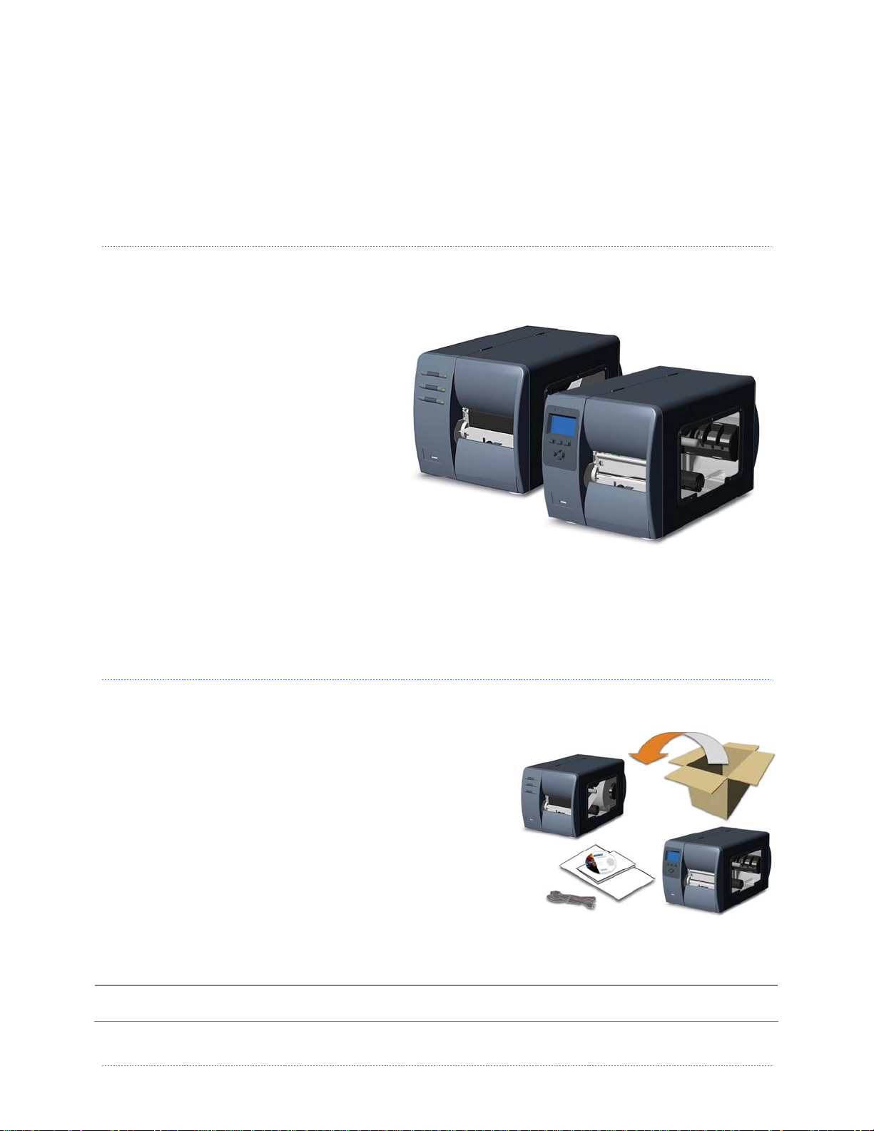
Congratulations on your M-Class Mark II printer purchase. The M-Class Mark II printer family,
hereafter referred to as ‘the printer’, blends the rugged durability of die-cast construction with
state-of-the-art electronics and user-friendly features to redefine the standard in industrial
thermal printers. Available in direct and
optional thermal transfer
configurations, the printers use unique
front panel designs to simplify
operation, while its USB, RS232 serial,
IEEE 1284 compliant parallel, or
optional wired and wireless LAN
connectivity allows eas y i n t e r fa c in g to
any host system.
This manual provides all the information
necessary to operate the printer.
To print labels or tags, simply refer to
the instructions included with the
software you have chosen to create the
labels. A Windows™ printer driver can
be found on our website (http://www.datamaxcorp.com/) or on the included CD-ROM for printing
from common applications. If you wish to write a custom program, a copy of the Class Series
Programmer’s Manual can also be found on the CD-ROM.
1
.
2
1
.
2
1
.
2
I
n
t
r
o
d
u
c
c
d
d
c
c
k
u
k
k
u
t
c
t
c
i
n
i
n
i
n
I
n
t
r
I
U
n
n
n
n
o
t
r
o
p
a
p
a
p
a
U
U
e
e
i
o
i
o
t
i
g
g
g
o
t
t
n
n
n
t
t
i
i
n
n
g
g
S
S
t
t
a
a
r
r
t
t
e
e
d
d
d
e
t
r
a
t
S
g
n
i
t
t
e
After removing the printer from the packaging material, check the contents. The following items
should be included:
Printer
Power Cord
CD-ROM and Documentation
Any special or additionally purchased items
Additional Requirements
The following items are necessary for generating labels
from your printer. Contact your customer support or
sales representative for advice on which media and
software may best be suited for your application.
Serial, USB or Parallel cable
Ethernet cable for optional LAN connectivity
Applicable Media
L
Chapter 1 – Getting Started 1
It is a good idea to save all packaging materials in the event that shipping the printer is ever
required.
Page 8

2 Chapter 1 – Getting Started
Page 9
P
P
P
2
2
2
2
.
1
2
.
1
2
.
1
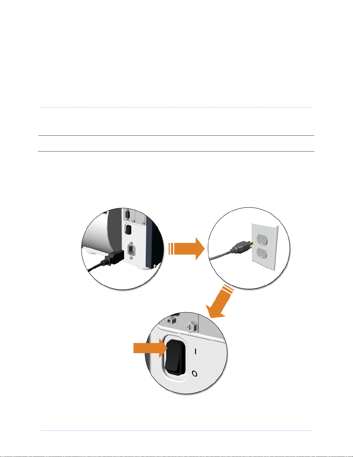
Power Connection
;
P
r
i
n
t
e
r
P
r
i
n
P
r
i
n
Before connecting the AC Power Cord or interface cables to the printer, ensure the Power On/Off
Switch is in the ‘Off’ position.
1. Place the printer on a firm, level surface.
2. Ensure that the Power Switch on the Printer is in the ‘Off’ position.
3. Connect the AC Power Cord to the receptacle on the back of the Printer, and then plug the
AC Power Cord into a properly grounded outlet. (The power supply automatically detects
and then adjusts to the applied line voltage; see Appendix A for the acceptable voltage
ranges.)
C
t
e
r
C
t
e
r
C
r
r
r
o
o
o
n
n
n
i
i
i
n
n
n
n
n
n
e
c
e
c
e
c
p
u
t
e
S
r
e
t
e
t
e
t
t
i
o
n
s
o
o
n
n
s
s
t
i
t
i
r
r
S
S
e
e
t
t
u
u
p
p
Chapter 2 - Printer Setup 3
Page 10
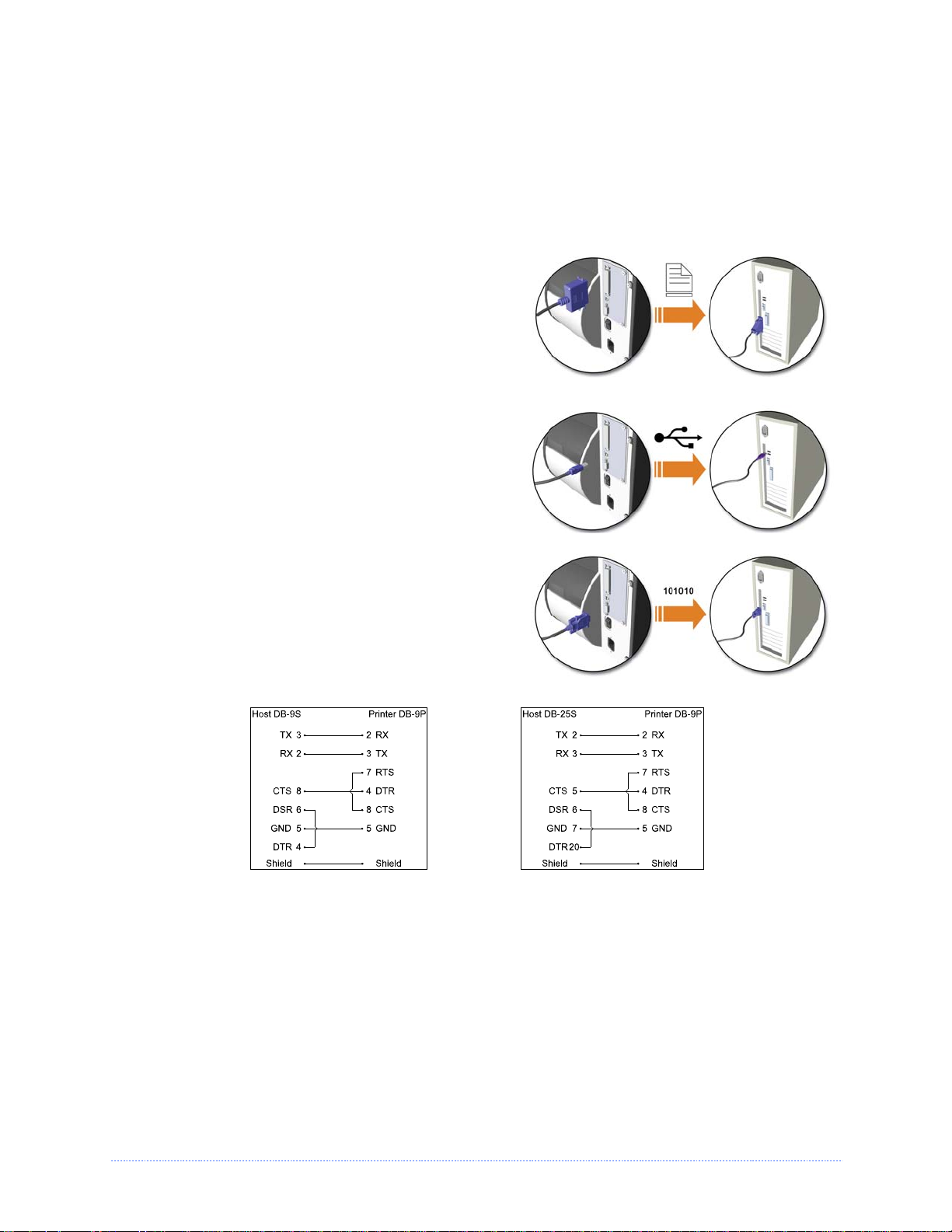
Interface Connection
The printer can be connected to the host via the parallel, USB, serial, or optional network
interface. The printer will automatically connect to the first port that delivers valid data. Once
established, the printer’s power must be cycled ‘Off’ and ‘On’ to change an interface connection.
A couple of Optional Ethernet Print Server (wired and wireless) are available. For
information on using these interfaces, refer to the instructions included with the option for proper
cabling, setup, and configuration.
The Parallel Connection needs a Centronics IEEE
1284 cable with a 36-pin male connector for
unidirectional (forward channel) communications, or
an IEEE 1284 Compliant cable for bi-directional
communications (forward and reverse channels).
Also, for bi-directional communications your host
must have supporting software.
The USB Connection needs a USB cable and is
supported in Windows
systems. Depending upon the operating system of
your host computer, installation requirements may
differ slightly.
95 and greater operating
The Serial Connection needs a serial interface
cable with specific pin-outs for proper
communications (part numbers and pin-outs are
given, below; contact your reseller to order). The
interface supports RS-232C communications via a
DB-9 connector. Serial port settings are menuselectable and must match your host’s serial port
settings.
Part # 32-2300-01 Part # 32-2301-01
4 Chapter 2 - Printer Setup
Page 11
2
.
2
L
o
a
d
i
n
g
M
e
d
i
a
2
.
2
L
o
a
d
i
n
g
M
2
.
2
L
o
a
d
i
n
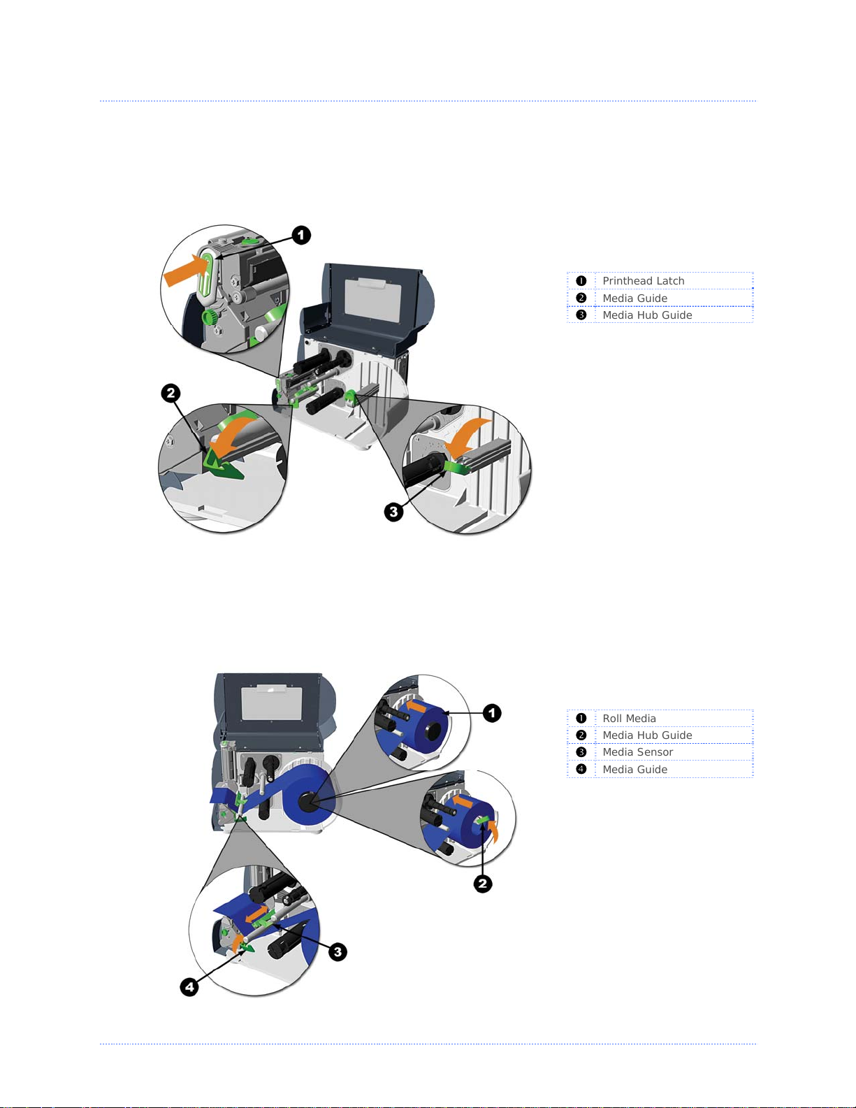
Load media into the printer as follows:
1. Open the media cover and lower the Media Hub Guide and Media Guide.
2. Press in on the Printhead Latch and raise the Printhead Assembly.
g
M
e
e
d
d
i
a
i
a
Printhead Latch
n
Media Guide
o
Media Hub Guide
p
3. Slide the Roll Media onto the Media Hub and raise the Media Hub Guide. The Media Hub Guide
should be pushed inward so that it is just touching the Roll Media.
4. Route the Media through the printer as shown. Raise the Media Guide. The Media Guide
should be pushed inward so that it is just touching the edge of the Media.
Roll Media
n
Media Hub Guide
o
Media Sensor
p
Media Guide
q
Chapter 2 - Printer Setup 5
Page 12
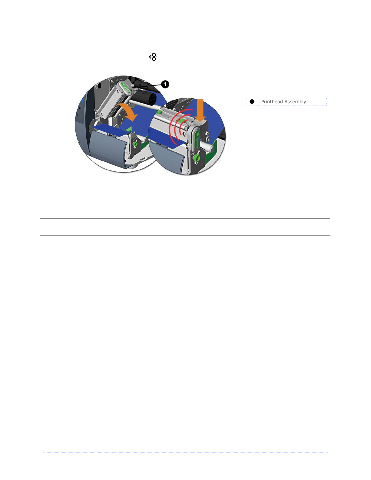
5. Close the Printhead Assembly and press down until it locks into place.
6. Close the cover and press the
proper tracking.
FEED
button several times to position the media and ensure
n
Printhead Assembly
If the printer does not correctly sense the top of each label, it may be necessary to calibrate the
printer. See section 3.5 Media Calibration.
The printer is factory set to use 4-inch media (and ribbon, if thermal transfer equipped). When using
;
a different width of media/ribbon, please refer to section 5.3.
6 Chapter 2 - Printer Setup
Page 13
2
.
3
M
e
d
i
a
S
e
n
s
o
r
A
d
j
u
s
t
m
e
n
t
2
.
3
M
e
d
i
a
S
e
n
s
o
r
A
d
j
u
s
t
2
.
3
M
e
d
i
a
S
e
n
s
o
r
A
d
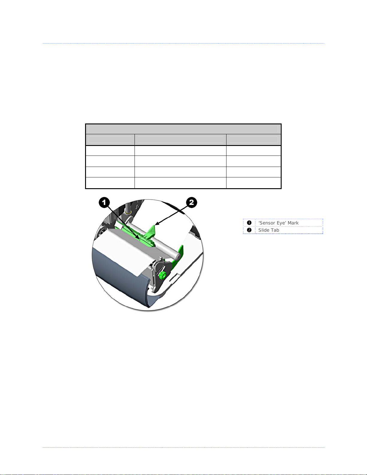
The Media Sensor needs to be positioned so that the printer can detect the presence of media and
the top-of-form (except for continuous stock, where the TOF is set through the front panel.
To adjust:
1. With media loaded, as described in Section 2.2, grasp the Slide Tab and move the Sensor
Eye Mark into position over media according to the table below.
2. If loading media, return to the media loading instructions.
Media Sensor Selection and Adjustment
Media Type Sensor Eye Mark Position Sensing Required
Die-cut Near the middle of the label Gap
Notched Centered over the notch Gap
Reflective Centered over the black mark Reflective
Continuous Near the middle of the media Continuous
m
j
u
s
t
m
e
e
n
n
t
t
‘Sensor Eye’ Mark
n
Slide Tab
o
Chapter 2 - Printer Setup 7
Page 14
2
.
4
L
o
a
d
i
n
g
R
i
b
b
o
n
2
.
4
L
o
a
d
i
n
g
R
i
b
2
.
4
L
o
a
d
i
n
g
Ribbon is required with thermal transfer media. It is recommended that the width of the ribbon be
slightly wider than the media being used. The printer can use either ribbons with the ‘coating side
in’ or
ribbons with the ‘coating side out’. To load:
Using a ribbon that is slightly wider than your media (and liner, if any) will help protect against
;
printhead wear.
1. Open the media cover.
Press in on the Printhead
Latch and raise the
printhead assembly.
b
R
i
b
b
o
o
n
n
Printhead Latch
n
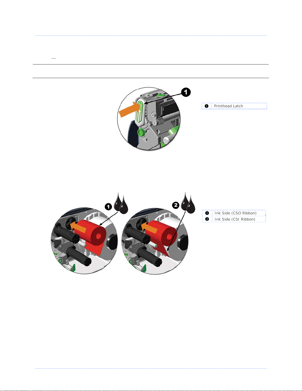
2. Slide the Ribbon Roll onto the Ribbon Supply Hub until it rests against the hub’s flange. Ensure
the ribbon unwinds in the correct direction (see Ribbon Routing). The illustrations here depict a
‘Coated Side In’ ribbon.
Ink Side (CSO Ribbon)
n
Ink Side (CSI Ribbon)
o
8 Chapter 2 - Printer Setup
Page 15
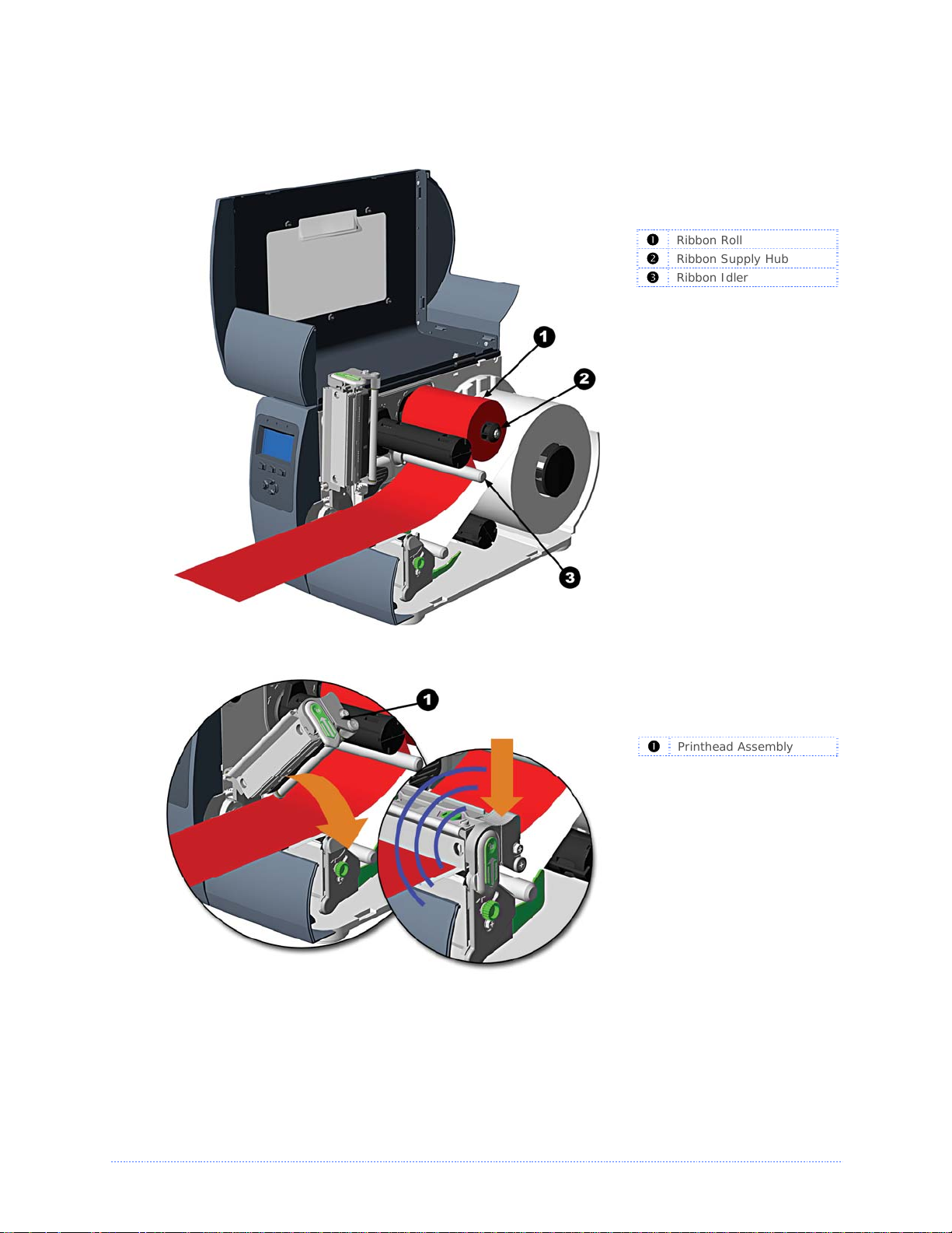
3. Route the ribbon under the Ribbon Idler and then out the front of the printer approximately 12
inches.
Ribbon Roll
n
Ribbon Supply Hub
o
Ribbon Idler
p
4. Close the Printhead Assembly and press down until it locks into place.
Printhead Assembly
n
Chapter 2 - Printer Setup 9
Page 16
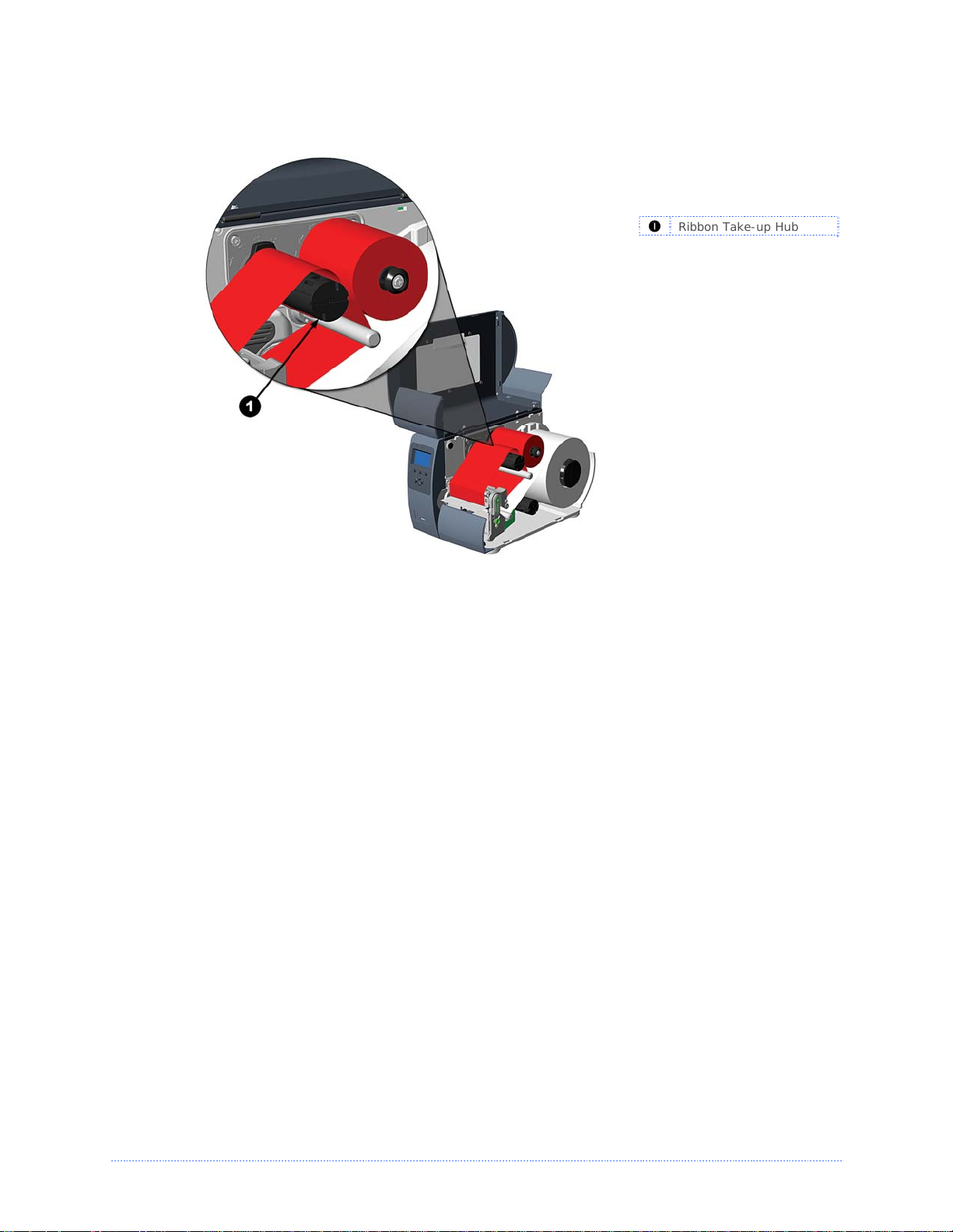
5. Route the ribbon up and then around to the Ribbon Take-Up Hub, winding it several times in a
clockwise direction to secure it in place.
Ribbon Take-up Hub
n
6. Close the cover and press the Feed button several times to position the ribbon and ensure proper
tracking.
7. The ‘Media Type’ setting within the printer’s setup must be set to ‘Thermal Transfer’ to print using
a ribbon. This can be accomplished with the DMXConfig Utility, (see section 3. 4) or on printers
equipped with a display - through the printers menu system, (see section 4.5).
10 Chapter 2 - Printer Setup
Page 17
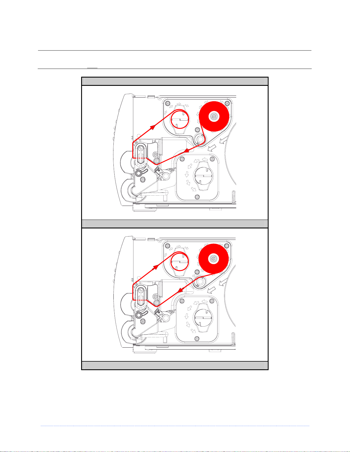
Ribbon Routing (Coated Side In & Coated Side Out)
Directional Arrows near the Ribbon Supply Hub indicate the correct ribbon route. Ribbon types are
;
available with the ink (coating) layer wound ‘in’ or ‘out’. Ensure the inked side of the ribbon faces the
media and NOT
the printhead.
Ribbon Routing Diagrams
(CSI) ‘Coating Side In’ Ribbon Routing
(CSO) ‘Coating Side Out’ Ribbon Routing
Chapter 2 - Printer Setup 11
Page 18

12 Chapter 2 - Printer Setup
Page 19
O
r
e
t
n
i
r
P
P
P
3
3
3
3
.
1
3
.
1
3
.
1
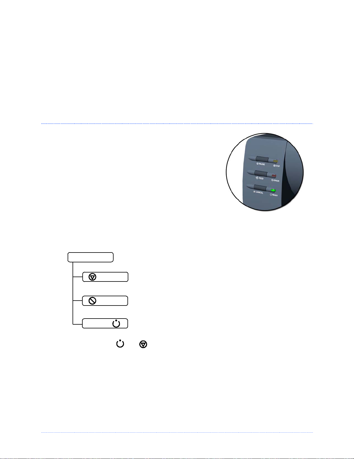
The Front Panel consists of three indicator lights and three
function buttons. The functions of these lights and controls
are listed in the following sections.
Non-display printers can be configured using the DMXConfig
Utility (see section 3.4). The printer can also be configured
using the Paper Menu Setup, (see Appendix C) for users that
do not have a host connection available.
F
r
o
n
t
P
F
r
o
F
n
r
o
n
a
t
P
a
t
P
a
n
n
n
r
r
e
e
e
i
i
l
(
l
(
l
(
n
n
N
o
N
o
N
o
n
n
n
t
t
-
-
-
e
e
D
D
D
r
i
s
p
i
s
p
i
s
p
r
l
a
l
l
a
a
y
y
y
O
O
P
r
P
r
P
r
p
i
n
i
n
i
n
p
p
e
t
t
e
e
t
e
e
e
r
s
r
s
r
s
n
o
i
t
a
r
a
r
a
r
)
)
)
t
t
i
i
o
o
n
n
3.1.1 Lights
(Normal power-up)
Normal Mode
Both the
STOP
ERROR
READY
READY
Solid On:
Flashing:
a label is presented to the operator.
Indicates a top of form or mechanical error has occurred
Solid On:
Flashing:
and
Indicates the printer is in the ‘Paused’ state
(When using the Peel & Present Option) Indicates
Indicates the printer is on and ready for printing
Indicates the printer is receiving data from the host
STOP
Lights will be on during power-up initialization.
Chapter 3 - Printer Operation 13
Page 20
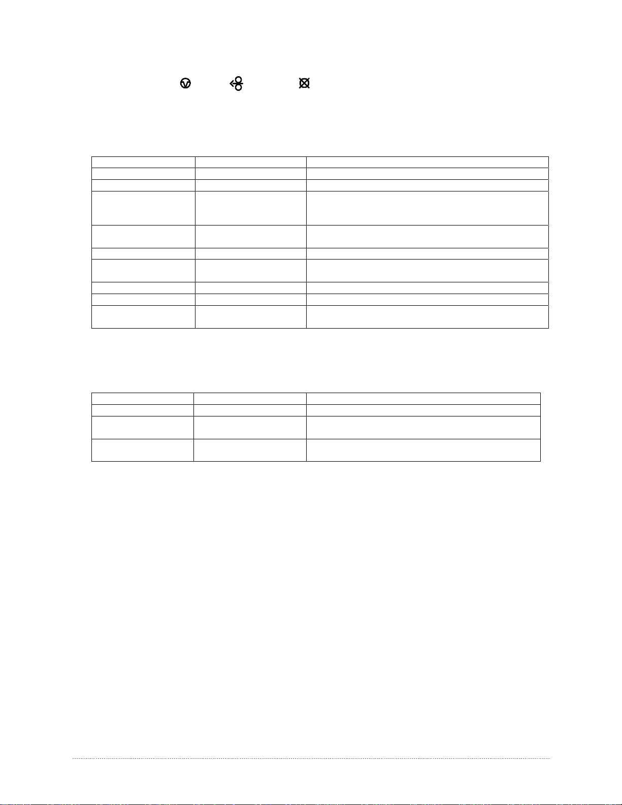
3.1.2 Buttons
The three buttons,
PAU S E
,
FEED
, and
CANCEL
perform different functions based on the
printer’s operational mode.
Ready Mode Functions
These functions can be performed at any time when the printer is at idle.
Function Button(s) Description
Pause Pause Pauses and un-pauses the printer
Feed / Clear Fault Feed Feeds one label or clears fault condition
Cancels the current batch of labels. Press the
Cancel Cancel
Pause button to print the next batch of labels in
the printers buffer.
Soft Reset
Press and Hold
Pause & Cancel
Resets the printer, see section 5.8
Print Test Label Pause & Feed Prints the Test Label
Print Configuration
Label
Feed & Cancel Produces Database Configuration and Test Label
Print Ethernet Label Pause, Feed & Cancel Prints the printers Ethernet configuration
Quick Calibration Press and Hold Feed Performs a “Quick Calibration”, see section 3.5
Empty Calibration
Press and Hold Pause
& Feed
Performs a “Empty Calibration”, see section 3.5
Delayed Power-up Functions
Turn on the printer, when the three lights turn on press and hold the button sequence. Continue to ho ld the
button(s) until the three lights turn off.
Function Button(s) Description
Hex Dump Feed Enters Hex Dump Mode, see section 6.3
Level 1 Reset Pause & Cancel
Level 2 Reset Pause, Feed & Cancel
Resets the printer to a saved configuration file,
see section 5.8.
Resets the printer to the default factory
settings, see section 5.8.
14 Chapter 3 - Printer Operation
Page 21
3
.
2
F
r
o
n
t
P
a
n
e
l
(
D
i
s
p
l
a
y
P
r
i
n
t
3
.
2
F
r
o
n
t
P
a
n
e
l
(
D
i
s
p
l
a
y
3
.
2
F
r
o
n
t
P
a
n
e
l
(
D
i
s
p
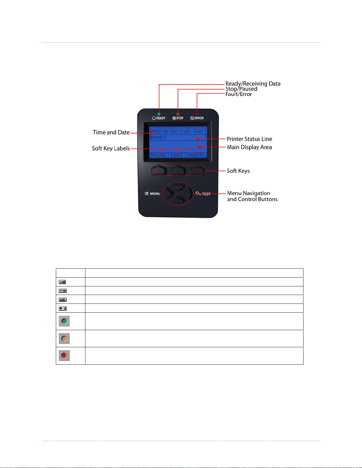
The Control Panel is an event-driven interface composed of a graphic display and keyboard. In
addition to providing current printer information, the mode-dependent panel allows the items in
the Main Display Area and the keyboard functions to change as operational events require.
P
l
a
y
P
e
r
i
n
t
e
r
i
n
t
e
r
s
)
)
r
s
r
s
)
Icons & Indicators
The icons are graphics that appear in the ‘Printer Status Line’ area of the display. Three LED
indicators are located above the display. Both provide real-time operational information as defined
below:
Item Definition
A USB Host device (memory drive or keyboard) has been detected
RFID is installed
A wired LAN connection has been detected
A wireless LAN connection has been detected
The printer is receiving data
The printer is stopped or paused
A Fault condition has been detected. For a listing of possible messages, see Section
6.2
Chapter 3 - Printer Operation 15
Page 22
3
.
3
W
i
n
d
o
w
s
D
r
i
v
e
r
3
.
3
W
i
n
d
o
w
s
D
3
.
3
W
i
n
d
o
w
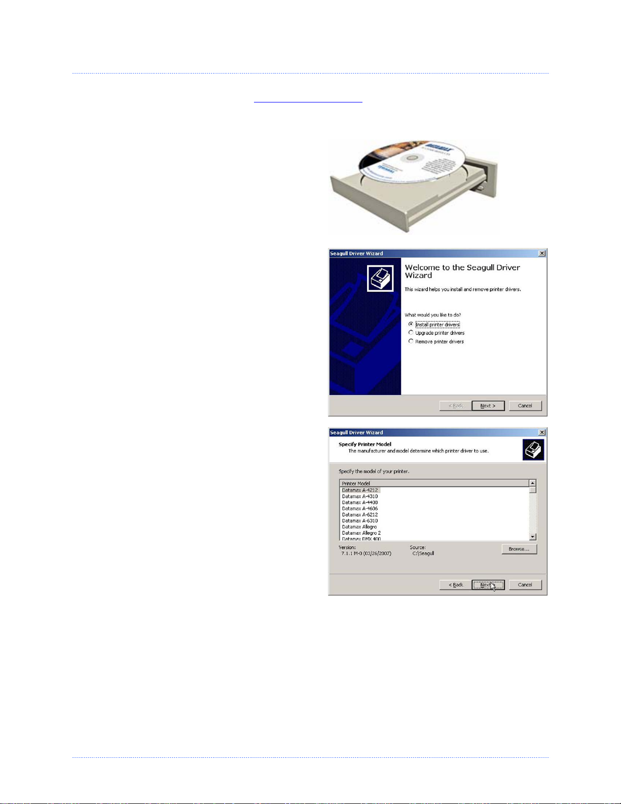
The Windows driver is located on the Accessories CD-Rom included with your printer. For the latest
version please visit our web site at www.datamaxcorp.com
Installing the Windows Driver:
Place the Accessories CD-Rom included with
your printer into your computers CD-Rom drive.
Once the CD-Rom starts, select "Install Windows
Driver" from the main menu and follow the
instructions on the screen to install.
When prompted, select your printer from the
list, (i.e. Datamax M-Class MarkII). Continue to
follow the on-screen instructions to install the
driver.
s
r
D
r
i
v
e
r
i
v
e
r
.
16 Chapter 3 - Printer Operation
Page 23
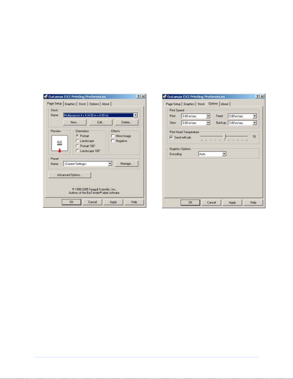
Important Notes:
The Windows driver functions the same as any other Windows printer. A built in help file is available for
complete information on all settings, however there are some important settings that should be
observed for trouble free printing.
Page Setup Tab: Stock
It is important that the Stock setting matches
the size of the label you are using. If you
cannot find a match for your label click 'New'
and enter the dimensions of your label.
Options Tab: Print Speed & Printhead
Temperature
These two settings will have the greatest effect
on print quality. Some label stocks will require
more heat and slower print speeds to generate a
quality image.
The Windows application software used to create the label format will likely have a "Page Setup"
screen. This will also need to match the size of the label you are using.
Chapter 3 - Printer Operation 17
Page 24
3
.
4
P
r
i
n
t
e
r
C
o
n
f
i
g
u
r
a
t
i
o
n
U
t
i
3
.
4
P
r
i
n
t
e
r
C
o
n
f
i
g
u
r
a
t
i
o
3
.
4
P
r
i
n
t
e
r
C
o
n
f
i
g
u
r
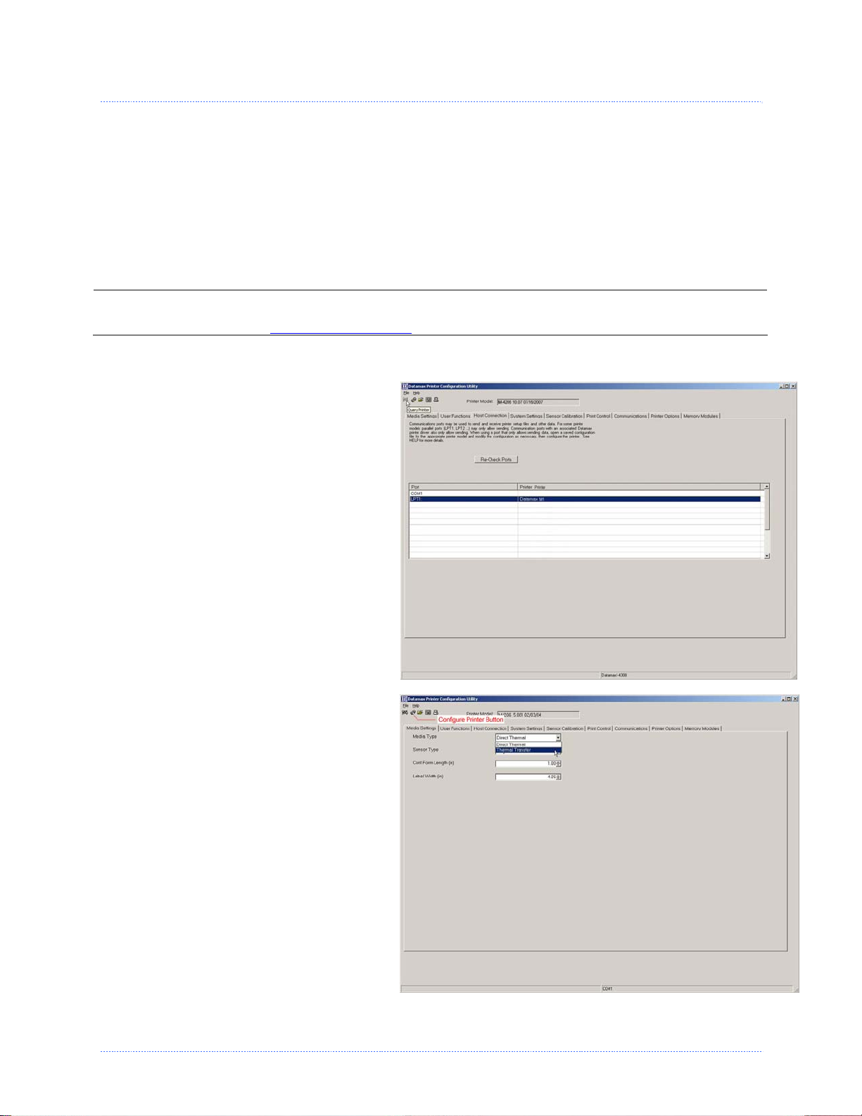
DMXConfig (located on the Accessories CD-ROM) is a windows based configuration utility that allows
the user to make changes to the existing printer setup via a direct connection to the host computers
serial and parallel connection.
DMXConfig Features:
Allows Real-Time Control/Query of Printer Configuration
Define and Save Optimal Configurations for Applications
Saved Configurations can be Shared with other Printers and Sent via Email
Download Files, Formats and Fonts
Query Memory Modules
Be sure to use the DMXConfig utility located on the Accessories CD-Rom that is included with your
;
printer. Older versions might not operate correctly with some printers. For the latest version please
visit our web site at www.datamaxcorp.com
Once you have installed the DMXConfig utility:
1. Connect the host to the printer with
a serial or parallel cable.
2. Turn on the printer.
3. Launch the DMXConfig utility.
4. Query the printer by using the
‘Query Printer’ toolbar button (topleft). This will connect to the printer
and get the current printer settings.
5. At this point you may browse the
tabs and make any changes
necessary to the printer
configuration. Once complete, send
the new settings to the printer using
the ‘Configure Printer’ toolbar
button. The example below
illustrates changing the Media Type
setting to “Thermal Transfer.
6. Select the ‘Media Settings’ tab, in the
‘Media Type’ drop-down box select
‘Thermal Transfer’.
7. Send the settings to the printer
using the ‘Configure Printer’ toolbar
button.
The printer is now configured to
‘Thermal Transfer’. You may close the
DMXConfig utility and begin printing
using ribbon.
a
n
t
i
o
n
l
U
t
i
U
t
i
.
(
D
M
X
C
o
n
f
i
g
)
i
t
y
(
D
M
X
C
o
l
i
t
y
(
D
l
i
t
y
M
X
C
o
n
n
f
i
g
)
f
i
g
)
18 Chapter 3 - Printer Operation
Page 25

3
.
5
M
e
d
i
a
C
a
l
i
b
r
a
t
i
o
n
3
3
.
5
M
e
d
i
a
C
a
l
i
b
r
a
.
5
M
e
d
i
a
C
a
l
i
b
t
r
a
i
o
n
t
i
o
n
3.5.1 Quick Calibration
Quick Calibration should be performed as part of the media loading routine to fine-tune the
sensing parameters.
(1) This calibration is not necessary when using continuous stock.
;
(2) Media containing large gaps may require a change in the PAPER OUT DISTANCE before proceeding.
Calibrate the printer as follows:
1. Ensure that the printer is ON and in an idle state (i.e., not off-line) with media loaded, the
media sensor adjusted, and the sensor type selected.
2. Press and hold the FEED Key until one label has been output then release the key and wait for
the printer to process the data. There are two possible outcomes:
Non-Display Printers:
Upon completion, one of the following lights will flash five times to denote the result of the
auto calibration attempt:
STOP
light = Successful calibration.
ERROR
light = Unsuccessful calibration, try again. If the calibration continues to fail
proceed to Section 3.5.2.
Display Printers:
CALIBRATION COMPLETE - will be displayed, and the media will be advanced to the next top
of form if calibration was successful; or,
CANNOT CALIBRATE will be displayed if calibration was not successful. In this case, check
the hints listed below to help resolve the problem:
Calibration Hints:
WARNING LOW BACKING (display printers only) is a normal message when calibrating diecut media mounted on a highly translucent liner or notched tag stocks.
If the initial attempt fails, press and hold the FEED Key until two successive label TOFs have
been output. If, however, CANNOT CALIBRATE is displayed again, perform the Standard
Calibration routine, see section 3.5.2.
3.5.1 Empty Calibration
Empty Calibration calibrates the printer’s media sensor to detect an ‘Out of Stock’ condition.
Calibrate the printer as follows:
1. Ensure that the printer is ON and in an idle state (i.e., not off-line) with media removed.
2. Press and hold the Pause & Feed Key for a few seconds.
Chapter 3 - Printer Operation 19
Page 26
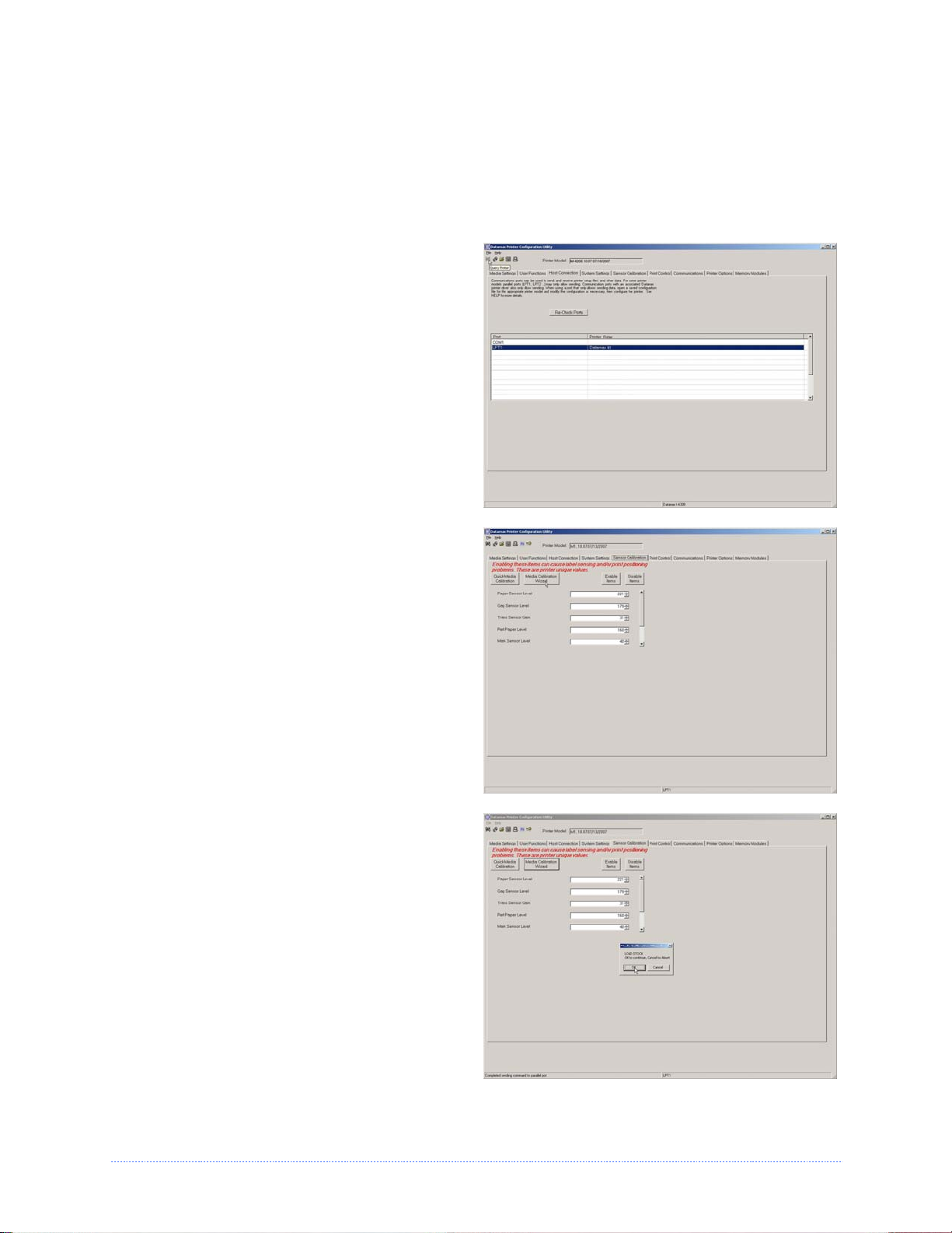
3.5.2 Standard Calibration
The Standard Calibration can be performed using the DMXConfig Utility, (see section 3.4 for more
information on DMXConfig) and using the front panel buttons (see Appendix C for more
information). On display equipped printers the Standard Calibration routine can also be initiated
via the printer’s menu, see section 4.5. Once you have installed the DMXConfig utility and the
printer is properly loaded with media:
1. Connect the host to the printer with a
serial or parallel cable.
2. Turn on the printer.
3. Launch the DMXConfig utility.
4. Query the printer by using the ‘Query
Printer’ toolbar button (top-left). This will
connect to the printer and get the current
printer settings.
5. Select the “Sensor Calibration” Tab and
then click the “Media Calibration Wizard”
button. When prompted click “OK” to start
the calibration wizard.
6. The Calibration Wizard will now prompt
you to ‘Load Stock’. Be sure the media is
properly loaded in the printer. Close the
printhead and click “OK”.
20 Chapter 3 - Printer Operation
Page 27
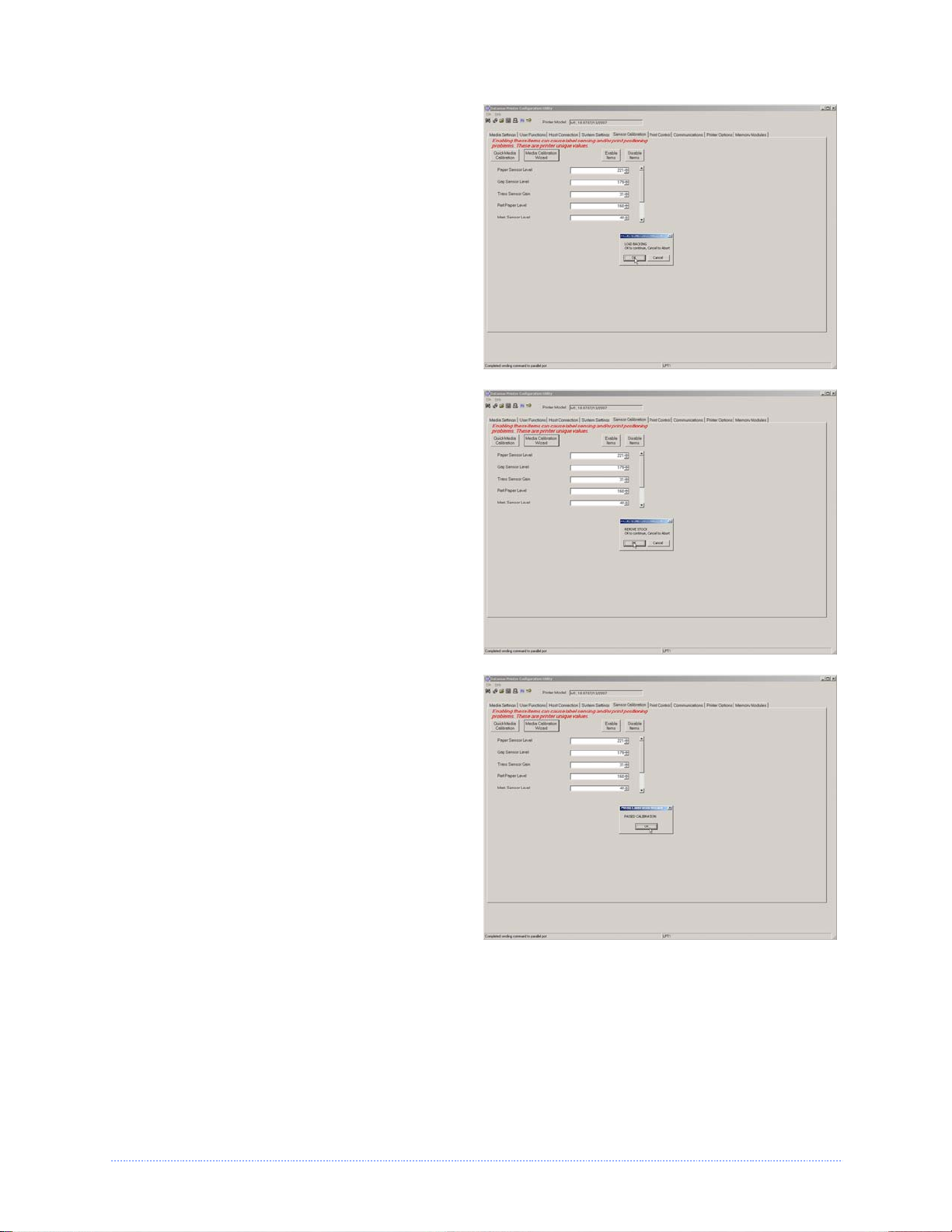
7. The Calibration Wizard will now prompt
you to ‘Load Backing’. Peel off a few labels
and position the backing material in the
media sensor. Close the printhead and
click “OK”.
8. The Calibration Wizard will now prompt
you to ‘Remove Stock’. Remove all media
and backing from the printer. Close the
printhead and click “OK”.
9. The Calibration Wizard will now respond
with ‘Passed Calibration’, click “OK” Reinstall the media in the printer. Close the
printhead and press the Feed button to
test the calibration. Each press of the Feed
button labels should feed one label.
If the printer was unsuccessful in
calibrating. Retry the procedure beginning
at Step 5.
Chapter 3 - Printer Operation 21
Page 28

22 Chapter 3 - Printer Operation
Page 29

m
e
t
s
y
S
u
n
y
y
y
s
s
s
e
e
e
t
e
t
e
t
e
m
m
m
n
n
(
D
(
D
(
D
u
u
i
s
p
i
s
p
i
s
p
l
l
l
a
a
a
S
S
y
P
y
y
P
P
y
y
r
i
r
i
r
i
n
n
n
s
s
t
e
t
e
t
e
t
t
O
r
s
O
r
s
O
r
s
e
n
l
n
l
n
l
m
y
)
y
)
y
)
m
e
M
M
M
4
4
4
4
.
1
4
.
1
4
.
1
The Menu System contains three primary branches, each with a differing level of access to
secondary menus or functions:
;
The multi-purpose Menu, Test, and Navigation Buttons allow Menu System entry, negotiation,
and parameter selection functions:
M
e
n
u
M
e
M
e
The User Menu accesses basic printer settings and functions;
The Advanced Menu accesses all operational settings, functions, and diagnostics; and,
The Test Menu accesses a menu of test, user-defined, and previous label printing functions.
(1) Entering the Menu System takes the printer OFF-LINE and stops the processing of new data.
(2) Prompts may appear before menu access is granted and before changes are enacted; see
Security for details.
(3) Display contrast is adjustable: press and hold the MENU BUTTON to cycle through the contrast
range (this may take several seconds) then release the button when the desired appearance has
been achieved .
n
n
u
u
S
S
S
To print a label from the Test Menu, press the TEST BUTTON; and,
To change printer settings or perform diagnostics, press the MENU BUTTON then observe
the MENU WINDOW AREA for available selections. (When the number of selections
present is greater than can be shown, use the UP or DOWN BUTTONS to view those
additional items. Also, SOFT KEY LABELS are dynamic and change to denote the current
associated SOFT KEY functions.)
Chapter 4 – Menu System 23
Page 30

4
.
2
T
h
e
U
s
e
r
M
e
n
u
4
.
2
T
h
e
U
s
e
r
4
.
2
T
h
e
U
The User Menu contains basic selections in these menus:
Media Settings
Print Control
Printer Options
System Settings
(1) Some setting changes will only become effective (and saved) after selecting YES at the Save
Changes prompt.
;
4
4
4
(2) Labeling software may, in some cases, override the printer menu settings; see Advanced Menu
for details.
.
3
T
h
e
A
.
3
T
.
3
h
T
h
The Advanced Menu contains all setting, control, and functional selections in these menus:
Media Settings
Print Control
Printer Options
System Settings
Communications
Diagnostics
MCL Options
After selecting the Advanced Menu, it will be accessed whenever the MENU BUTTON is pressed.
To enable the Advanced Menu, proceed as follows:
1. Press the MENU BUTTON.
2. Using the UP or the DOWN BUTTON, scroll to SYSTEM SETTINGS then press the ENTER KEY.
3. Scroll to MENU MODE then press the ENTER KEY.
4. Scroll to ADVANCED MENU then press the ENTER KEY. (Upon completion, OK will be
displayed and the printer will exit the menu system.)
e
e
d
A
A
s
d
d
e
v
v
v
r
a
a
a
n
M
M
n
n
c
c
c
e
e
e
e
e
n
n
d
d
d
u
u
M
M
M
e
e
e
n
n
n
u
u
u
(1) Some setting changes will only become effective (and saved) after selecting YES at the Save
Changes prompt.
;
24 Chapter 4 – Menu System
(2) Labeling software may, in some cases, override the printer menu settings; see Advanced Menu /
Communications / Host Settings to avoid potential conflicts.
(3) To return to the User Menu, re-select it or restore the factory defaults.
Page 31

4
.
4
T
h
e
T
e
s
t
M
e
n
u
i
e
e
i
n
u
n
u
l
s
l
s
l
s
4
.
4
T
h
e
T
e
s
t
e
D
D
D
s
e
e
e
M
t
M
t
a
i
t
a
t
a
4
.
4
T
h
e
T
The Test Menu contains test and informational label selections:
Print Quality Label
Ribbon Test Label
Test Label
Validation Label
Print Configuration
Print Last Label
User Defined Label
Internally generated, these labels are printed at pre-selected media type, speed, and heat
settings. Changes to these print settings can be made via the Menu System or through host
commands. When printing, use full width media to capture the entire format; otherwise, adjust
the printer and set the Label Width.
(1) Press the CANCEL KEY to stop printing.
;
4
4
4
(2) A printing delay can be set; see Print Test Rate (in Diagnostics).
.
5
M
e
n
u
.
5
M
.
5
M
e
e
n
n
u
u
Media Settings
The Media Settings menu contains label and ribbon sensing and sizing functions, as well as
printhead cleaning selections:
Media Type
Sensor Type
Label Length
Maximum Label Length *
Paper Empty Distance *
Label Width
Ribbon Low Options *
Sensor Calibration *
Printhead Cleaning *
;
Items denoted with an asterisk (*) are only accessible through the Advanced Menu.
The menu selections are defined on the following pages:
Chapter 4 – Menu System 25
Page 32

DISPLAYED ITEM ITEM DESCRIPTION
MEDIA TYPE Selects the method used to print labels and should be set according to the type
of media being used, where:
DIRECT THERMAL Sets use for media that is heat reactive to produce an image.
THERMAL
TRANSFER
SENSOR TYPE Selects the top-of-form (TOF) sensing method used to determine the leading
GAP TOF will be recognized by sensing the gaps or notches in the media. (Default
CONTINUOUS No TOF sensing will be used; instead, LABEL LENGTH (in Media Settings) is used.
REFLECTIVE TOF will be recognized by sensing the reflective (black) marks on the underside
LABEL LENGTH Determines the length of the label (0 - 99.99 inches) when the SENSOR TYPE is
04.00 Is the default setting.
MAXIMUM LABEL
LENGTH
16.00 Is the default setting.
;
PAPER EMPTY
DISTANCE
00.25 Is the default setting.
;
LABEL WIDTH Sets the maximum printable width. Objects extending beyond this setting will
x.xx Default setting is dependant on printer model.
RIBBON LOW
OPTIONS
RIBBON LOW
DIAMETER
PAUSE ON RIBBON
LOW
ENABLE Pauses when a Ribbon Low Diameter condition is detected; the PAUSE Key must
DISABLE No action is required by the operator; printing can continue until a Ribbon Fault is
Maximum Label Length should typically be 2.5 to 3 times the physical length of the label.
When using clear or translucent media, this setting should be longer than the actual label size.
1.38 Is the default setting.
Sets use for media that requires a ribbon to produce an image.
edge of the label, where:
Setting)
of the media.
set to CONTINUOUS, where:
Sets the distance (0 - 99.99 inches) that the printer will feed media to find TOF
(when the Sensor Type is set to GAP or REFLECTIVE) before a TOF Fault is
declared, where:
Sets the distance (0 - 99.99 inches) the printer will attempt to feed before an
Out Of Stock Fault is declared, where:
NOT print, where:
Defines the printer response when THERMAL TRANSFER mode is selected and the
ribbon supply begins to diminish.
Sets the ribbon supply threshold diameter (1.00 - 2.00 inches) that will trigger a
Low Ribbon Warning prompt, where:
Allows the printer to enter a paused condition when Ribbon Low Diameter is met,
where:
be pressed to proceed with the print job.
declared. (Default Setting)
26 Chapter 4 – Menu System
Page 33

SENSOR
CALIBRATION
PERFORM
CALIBRATION
ADVANCED ENTRY Sets the values via manual entry (typically for hard to calibrate label stocks), as
PAPER SENSOR
LEVEL
REFL PAPER
LEVEL
GAP SENSOR
LEVEL
MARK SENSOR
LEVEL
EMPTY
SENSOR LEVEL
TRAN SENSOR
GAIN
REFL SENSOR
GAIN
PRINTHEAD
CLEANING
CLEAN HEAD
SCHEDULE
CLEAN HEAD
COUNTER
RESET COUNTER Resets the Clean Head Counter to zero to restart the Clean Head Schedule.
CLEAN HEAD
NOW
Selects the method used to calibrate the media sensor, where:
Sets the values via internal printer calculations, as described in the STANDARD
CALIBRATION procedure.
described in the ADVANCED ENTRY CALIBRATION where:
Establishes the threshold for the paper value (0 - 255), where 170 is the default
setting.
Establishes the threshold for the reflective value (0 - 255), where 170 is the
default setting.
Establishes the threshold for the gap value (0 - 255), where 040 is the default
setting.
Establishes the threshold for the mark value (0 - 255), where 040 is the default
setting.
Establishes the threshold for the empty value (0 - 255), where 000 is the default
setting.
Establishes the sensitivity of the transmissive sensor (0 - 31), where 15 is the
default setting.
Establishes the sensitivity of the reflective sensor (0 - 31), where 15 is the default
setting.
Controls the automatic cleaning alert and function, where:
Specifies the inch (or centimeter) count at which to clean the printhead. (Note
that the specified count [0 - 200 inches] will be multiplied by one thousand, and
zero [the default setting] will disable the function.) If this count is exceeded
three times, a Head Cleaning Fault will occur.
Indicates the number of inches (or centimeters) since a cleaning was last
initiated.
Initiates the cleaning process and resets the Clean Head Counter.
Chapter 4 – Menu System 27
Page 34

Print Control
The Print Control menu contains printing throughput, offset and custom setup functions:
Heat
Print Speed
Feed Speed
Reverse Speed *
Slew Speed *
Row Offset
Column Offset
Present Distance
Custom Adjustments *
;
Items denoted with an asterisk (*) are only accessible through the Advanced Menu.
The menu selections are defined as follows:
DISPLAYED ITEM ITEM DESCRIPTION
HEAT Controls the burn time (0 - 30) of the printhead (and is equivalent to the Heat
setting in many software labeling programs), where:
10 Is the default setting.
PRINT SPEED Controls the rate of label movement during printing, where:
x.x in/sec
FEED SPEED Controls the rate of label movement between printing areas, where:
x.x in/sec
REVERSE SPEED Controls the rate of label movement (2.0 - 5.0 inches per second) during backup
positioning, where:
4.0 in/sec Is the default setting.
SLEW SPEED Controls the rate of label movement (2.0 - 16.0 inches per second) between
printing areas when using the GPIO function, where:
x.x in/sec
ROW OFFSET Shifts the vertical start of print position (0 - 99.99 inches) on the label, where:
00.00 in. Is the default setting.
COLUMN OFFSET Shifts the HORIZONTAL, left-justified start of print position to the right (0-99.99
inches), without shifting the LABEL WIDTH termination point to the right, where:
00.00 in. Is the default setting.
28 Chapter 4 – Menu System
Page 35

PRESENT DISTANCE Sets the label stop position (0 - 4.00 inches) past the start of print position upon
output. When subsequent label formats are received, the printer will automatically
back up the label to position it at the start of print position, where:
AUTO
0.00 in.
Is the default setting (Auto Mode). In Auto Mode, the printer automatically
configures this distance according to the positioning requirements of the attached
device (i.e., tear bar, cutter, peel & present mechanism, or present sensor).
;
CUSTOM
ADJUSTMENTS
DARKNESS Controls the strobe time (1 - 64) to establish the nominal HEAT setting for
CONTRAST Allows fine-tuning (1 - 64) of the gray adjustment for print quality, where:
ROW ADJUST Shifts the vertical start of print position (in xxx dots) to fine-tune the ROW OFFSET
COLUMN ADJUST Shifts both the horizontal start of print position and the LABEL WIDTH termination
PRESENT ADJUST Adjusts the label stopping position (in xxx dots) to fine-tune the PRESENT
When set to 0.01 in., NONE is assumed and a zero (0) positioning value will be used.
Changes the factory adjustment parameters to finely and independently
compensate for slight mechanical differences sometimes evident when multiple
printers share label formats. These settings are also available to make special
label formatting adjustments, where:
printhead-specific thermal characteristics, where:
32 Is the default setting.
32 Is the default setting.
setting, where:
+000 If shifting Row Adjust in the negative direction, modify the PRESENT ADJUST
setting [see below] by that same amount.
point to the right (in xxx dots) to fine-tune the COLUMN OFFSET setting, where:
+000
DISTANCE setting, where:
+000
Chapter 4 – Menu System 29
Page 36

Printer Options
The Printer Options menu contains file-handling, module, and optional equipment settings:
Modules
Present Sensor
Cutter
RFID
Rewinder
Items denoted with an asterisk (*) are only accessible through the Advanced Menu; also, certain
;
selections will appear only when equipped with that option.
The menu selections are defined as follows:
DISPLAYED ITEM ITEM DESCRIPTION
MODULES Controls memory handling functions, where:
DIRECTORY * Allows viewing and printing of the available space and file types (including plug-in
files) present on a module. Only detected modules will be listed, and selecting ALL
will display all results. (See Module File Definitions for details.)
PRINT FILE Selects from a list of stored file types then prints, as noted below. (See Module File
Definitions for details.)
File Extension Printed Result
DBM A font sample.
DCM The configuration commands contained in the file.
DIM The image.
DLB The stored label.
DLN The name of the language.
DMS The database contained in the file for RFID.
DPL A label format, if detected.
DTT A font sample.
PLU The names of the files contained in the plug-in directory.
PROCESS FILE * Selects from a list of available files for processing, as noted below. (See Module
File Definitions for details.)
FORMAT
MODULE *
External File
Extension
BMP, PCX,
IMG, & F7B
BS Upgrades the printer boot-loader. --DPL If detected, a label format is printed. --LS Converts the translated message file, and then stores
PLG Converts the plug-in file, and then stores the result as
SFL & SFP Converts the bit-mapped font file and then stores the
TTF Converts the true-type / scalable font file and then
ZS Upgrades the printer firmware. ---
Converts the black and white graphics file, image flip
assumed, and then stores the result in Module G.
the result in Module Y.
specified by the file (typically Module X).
result in Module G, where the last three characters of
the name will correspond to the Font ID. (If the
filename does not contain a Font ID, you will be
prompted to enter it.)
stores the result in Module G, where the last two
characters of the name will correspond to the Font ID.
(If the filename does not contain a Font ID, you will be
prompted to enter it.)
Selects from a list of modules available for formatting by the printer. (See File
Handling Messages.)
Choosing FORMAT MODULE will erase existing data in the selected module
Definition / Action Converted
DIM
DLN
PLU
DBM
DTT
Internal
Extension
30 Chapter 4 – Menu System
Page 37

DELETE FILE * Selects from the list of available files for deleting. (See File Handling Messages.)
COPY FILE * Selects from the list of available files for copying, prompting you for the
destination module before execution. (See File Handling Messages.)
UNPROTECT
MODULE *
PRESENT SENSOR Controls the "on-demand" dispensing of labels , where:
MODE Sets the detection method and response of the printer:
AUTO Is the default setting. Automatically detects, enables the Present Sensor (or Peel
ENABLED Enables the Present Sensor (or Peel and Present mechanism) and sets the label
DISABLED Disables the option.
RETRACT DELAY * Programs a time delay for the retraction of the next label in the print process,
(1 - 255 x 10
mS)
070
CUTTER Controls the Cutter operation, where:
MODE Sets the detection method and response of the printer:
AUTO Is the default setting, where the presence of the cutter option is automatically
ENABLED Enables the cutter. If the cutter is not detected, a fault will be generated.
DISABLED Disables the cutter.
CUT BEHIND Allows a number of small labels to queue before a cut is performed to increase
(0 – 2)
0
RFID Controls the programming and verification of RFID tags, where:
RFID MODULE Sets the mode of RFID operation, where:
DISABLED Disables the option.
HF Selects the High Frequency (13.56 MHz) RFID option.
UHF MULTI-
PROTOCOL
RFID POSITION* Sets the RFID inlay location.
(1.10 - 4.00 IN.)
1.10
HF SETTINGS * Sets HF tag parameters, as follows:
TAG TYPE Sets the tag type:
AFI VALUE Application Family Identifier value (00 - FF), where 00 is the default value.
AFI LOCK Application Family Identifier lock (ENABLED / DISABLED), where DISABLED is the
Selects from the list of available modules to unprotect, and then prompting you
regarding the outcome of the attempt. (See File Handling Messages.)
and Present mechanism) and sets the label stop location; if not detected, the
operation will be ignored.
stop location; if not detected, a fault will be generated.
where:
Is the range, times 10 milliseconds; and,
Seventy (times ten) is the default setting.
sensed. If detected, the cutter is enabled; otherwise, it will be ignored.
throughput.
(1) This mode can be used without a cutter to allow the presentation of
an extra label with retraction upon the next job or feed operation.
;
Zero, one, or two are the number of labels to queue before cutting; and
Is the default setting.
;
Selects the Ultra High Frequency (868-956 MHz) RFID option.
This location is referenced from the leading edge of the label or tag, as it moves
forward through the printer.
Is the default setting.
ISO 15693 (Is the default setting.)
TI
PHILIPS
ST LRI512
ST LRI64
default setting.
(2) After a fault or unknown label position, the leading edge will be cut
to ensure no extra material exists at the beginning of the first label;
otherwise, the cutter will only cut when necessary.
If not installed (or detected), this selection will result in a DISABLED
message.
Chapter 4 – Menu System 31
Page 38

DSFID VALUE Data Storage Format Identifier (00 - FF), where 00 is the default value.
DSFID LOCK Data Storage Format Identifier lock (ENABLED / DISABLED), where DISABLED is
the default setting.
EAS VALUE Electronic Article Surveillance value (00 - FF), where 00 is the default value.
AUDIO
INDICATOR
ERASE ON
FAULT
Controls the buzzer (ENABLED / DISABLED), where DISABLED is the default
setting.
Erases the tag when errors are detected (ENABLED / DISABLED), where DISABLED
is the default setting.
UHF SETTINGS * Sets UHF tag parameters, as follows:
TAG TYPE Sets the tag type:
EPC 0
EPC 0+ MATRICS
EPC 0+ IMPINJ
EPC 1
UCODE EPC 1.19
EM 4022/1222
GEN 2 (Is the default setting.)
TAG DATA
SIZE
Sets the tag data size:
96-BIT (Is the default setting.)
64-BIT
POWER
Adjusts the applied power.
ADJUST
KILL CODE Code used to permanently deactivate the device:
B3 B2 B1 B0
00 00 00 00 (Is the default setting.)
ACCESS
CODE
Code used to protect the memory contents:
B3 B2 B1 B0
00 00 00 00 (Is the default setting.)
GEN 2 LOCK
ACTION
LOCK AFTER
Sets the lock level (NONE, PERMALOCK, PWD-READ/WRITE, BOTH), where NONE is
the default setting.
Locks the tag after programming.
WRITE *
ENABLED The tag will be locked.
DISABLED No locking occurs (default setting).
RETRY
Sets the number of retry attempts, where:
ATTEMPTS *
(0 - 9)
3
PERFORM
CALIBRATION *
Zero to nine are the number of retries; and,
Is the default setting.
Allows the printer to establish the tag to transducer distance setting and nominal
RFID power requirements.
YES Initiates the process. The CALIBRATING RFID message will appear as the printer
feeds media to begin scanning for the RFID tag location. Once the location is
established, power calibration begins. Upon completion, the media will be retracted
to the TOF position; the calibrated position and power results (along with a brief
SUCCESS or FAILURE message) will be displayed; and, the printer’s database will
be updated with the new calibration parameters.
NO Terminates the process.
SET DEFAULTS * Depending upon the RFID MODULE, selecting YES will return these settings:
If MODE = HF, then:
RFID POSITION = 1.10
HF SETTINGS:TAG TYPE = ISO 15693
RETRY ATTEMPTS = 3
--------------------------------------------------------------------------------------------
----
If MODE = UHF, then:
RFID POSITION = 1.10
UHF SETTINGS:TAG TYPE = GEN 2; TAG DATA SIZE = 96-BIT
RETRY ATTEMPTS = 3
32 Chapter 4 – Menu System
Page 39

System Settings
The System Settings menu contains label formatting, operation, and control functions:
Menu Mode
Configuration File
Internal Module D *
Default Module *
Scaleable Font Cache *
Single Byte Symbols *
Double Byte Symbols *
Time And Date
Media Counters *
Print Configuration *
Configuration Level *
Set Factory Defaults *
Format Attributes *
Label Rotation
Imaging Mode *
Pause Mode *
Peel Mode *
Security *
Units Of Measure *
Input Mode *
DPL Emulation *
Column Emulation *
Row Emulation *
SOP Emulation *
Back After Print *
Backup Delay (1/50s) *
Font Emulation *
Label Store *
Menu Language
Fault Handling *
;
Items denoted with an asterisk (*) are only accessible through the Advanced Menu.
The menu selections are defined as follows:
DISPLAYED ITEM ITEM DESCRIPTION
MENU MODE Sets the menu system access level, where:
USER MENU Accesses a limited menu of basic controls. (Default Setting)
ADVANCED
MENU
CONFIGURATION
FILE
RESTORE AS
CURRENT *
SAVE SETTING
AS
DELETE FILE * Removes a selected configuration file from memory. (An active file cannot be
FACTORY
SETTING FILE *
Accesses the full menu of controls, settings, and diagnostics.
Controls the creation, storage, and recall of printer configuration files, where:
Returns the printer to a previously saved configuration.
Creates a file based on the current printer configuration, as described here.
deleted.)
Provides a list of available configuration files used to restore the printer's
configuration following a Level One Reset or when YES is selected in the SET
FACTORY DEFAULTS menu. (NONE is the default file setting.)
Chapter 4 – Menu System 33
Page 40

INTERNAL MODULE D
1088 Is the Default Setting.
DEFAULT MODULE Designates the memory module to be used for file storage when none are
D Is the Default Setting (DRAM module).
G Flash module.
Sets the number of 1KB blocks (100 - 5120) allocated for the internal DRAM ‘D’
module, where:
specified, where:
;
SCALEABLE FONT
CACHE
0511 KBytes Is the Default Setting.
;
The available modules may vary depending upon printer model and options.
Configures the number of 1KB blocks (100 - 5120) allocated for the scaleable font
engine, where:
The available memory may vary depending upon printer model and options.
SINGLE BYTE
SYMBOLS
ARABIC-8 ISO 15: ITALIAN ISO 17: SPANISH
CYRILLIC LEGAL ISO 11: SWEDISH
ISO 60: DAN/NOR HP4000 ZAPF DINGBAT SYMBOL
DESKTOP MATH-8 TURKISH-8
ITC ZAPF DINGBAT/100 MACINTOSH PS TEXT
ITC ZAPF DINGBAT/200 PS-MATH UTF-8
ITC ZAPF DINGBAT/300 PC-858 MULTILINGUAL ISO 4: UK
PS ITC ZAPF DINGBAT MICROSOFT PUBLISHING ISO 6: ASCII
ISO 8859/1 LATIN 1 PC-8 CODE PAGE 437 VENTURA INTERNATIONAL
ISO 8859/2 LATIN 2 PC-8 D/N, CP 437N VENTURA US
ISO 8859/5 LATIN 5 PC-852 LATIN 2 VENTURA MATH
ISO 8859/10 LATIN 6 PC-851 LATIN/GREEK WINDOWS 3.1 LATIN 1
ISO 8859/7 LT/GK E7 PC-862 LATIN/ARABIC WINDOWS LATIN/ARABIC
ISO 8859/15 LATIN 9 PI FONT AGFA TIDBITS
ISO 8859/7 LT/GK EG PC-850 MULTILINGUAL WINDOWS 3.1 LATIN 2
ISO 8859/8 LATIN/HBR PC-864 LATIN/ARABIC WINDOWS LATIN/GREEK
ISO 8859/8 LATIN/CYR PC-8 TK, CP 437T WINDOWS 3.1 LATIN 5
ISO 69: FRENCH PC-1004 WINDOWS
GREEK-8 PC-775 BALTIC WINDOWS 3.0 LATIN 1
PC-8 GREEK PTXT3000 WINDOWS LATIN/CYRIC
ISO 21: GERMAN NON-UGL, PI FONT WINDOWS 3.0 LATIN 5
HEBREW-7 ROMAN-8
HEBREW-8 ROMAN-9
Selects the code page used to print single byte fonts, unless otherwise specified,
where:
;
Reference the Class Series Programmer’s Manual for code page symbol set details.
34 Chapter 4 – Menu System
Page 41

DOUBLE BYTE
SYMBOLS
JIS Japanese Industry Standard
SHIFT JIS Shift Japanese Industry Standard
EUC Extended UNIX Code
UNICODE Unicode (including Korean)
GB Government Bureau Industry Standard; Chinese (PRC)
BIG 5 Taiwan encoded
Selects the optional ILPC code page used to print double byte fonts, where:
;
TIME AND DATE Sets the printer's time and date.
MEDIA COUNTERS Displays and controls various internal counters, where:
ABSOLUTE
COUNTER
PRINTHEAD
COUNTER
RESETTABLE
COUNTER
RESET COUNTER Returns the Resettable Counter to zero.
PRINT
CONFIGURATION
;
Reference the Class Series Programmer’s Manual for the code page symbol set details.
Shows the total number of inches printed and the date the counter was set (non-
resettable).
Shows the total number of inches printed (not user-resettable).
Shows the number of inches printed since the last reset (user-resettable).
Produces a Configuration Label using the printer's current database information.
(To generate the label, shown here, press the RIGHT Button or the ENTER Key. )
(1) The information on this label may vary with the model, firmware version and installed
options.
(2) To capture all the data, use media that is at least 2 inches (51 mm) wide and set the
Label Width (in Media Settings) according to the width of your labels.
(3) Menu settings that require a reset to become effective will be indicated with a section
symbol (§), while bulleted () items denote host changes not yet saved.
CONFIGURATION
LEVEL
PRINTER KEY
APPLICATION
VERSION
BOOT LOADER Displays the version level and date of the boot loader.
UPGRADE
PRINTER CODE
UNLOCK
FEATURE
Displays the hardware and software levels of the printer, where:
;
Identifies the unique key number of the printer, in the form: vvvv-cwxx-yyyyyy-
zzz, where:
vvvv - Represents the printer model number.
cwxx - Represents the hardware/software feature level, where:
c - Represents the printer class.
w - Represents hardware feature level of the main board.
xx - Represents the software feature level 10 = standard DPL, and 20 = Internal
CG Times Font. Features are accepted up to the this value, but increases beyond
the range will require an authorization code.
yyyyyy - Is the manufacturing date code.
zzz - Is a unique time stamp.
Displays the level, version number, and date of the application firmware.
Upgrades the software feature level of the printer.
Unlocks additional optional features within the printer. (An authorization code is
required.)
This information is also provided on the Configuration Label.
Chapter 4 – Menu System 35
Page 42

SET FACTORY
DEFAULTS
FORMAT
ATTRIBUTES
TRANSPARENT Intersecting text, images, and bar codes will be printed, for example:
XOR Intersecting text, images, and bar codes will not be printed, for example:
OPAQUE Intersecting text, images, and bar codes will be printed by obliterating those
LABEL ROTATION Allows the label format to be rotated 180 degrees before printing, where:
ENABLED Flips the format.
DISABLED Does not flip the format. (Default Setting)
IMAGING MODE Determines the process used to format labels, where:
MULTIPLE LABEL Images multiple labels as memory permits to achieve the fastest throughput. If
SINGLE LABEL Images the next label only after the previous label has been printed, providing the
PAUSE MODE Allows for controlled interactive printing, where:
ENABLED Requires the user to press the PAUSE Key to print each label.
DISABLED Labels are printed without pausing. (Default Setting)
PEEL MODE Allows the printer to wait until the Start of Print signal is received (via the optional
ENABLED Inhibits the feed function until the Start of Print signal is received.
DISABLED Feeds the label regardless of the Start of Print signal. (Default Setting)
SECURITY Allows all or part of the User Interface to be password-protected and for that
SELECT
SECURITY
DISABLED No password is required for menu access. (Default Setting)
SECURE
MENU
MENU AND
TEST
ADVANCED
MENU
MODIFY
PASSWORD
To be activated, the password must initially be set to a value other than the default setting
;
(0000).
Returns the printer settings to the factory-programmed values (except CUSTOM
ADJUSTMENTS and calibrations); or, if selected, to the Factory Setting File, where
selecting YES at the prompt causes the configuration to be restored.
Defines the manner in which overlapping text and graphics appear when printed,
where:
(Default Setting)
formatted first, for example:
time-stamping labels, however, the indicated time will reflect the moment of
imaging rather than the actual print time. (Default Setting)
most accurate time-stamps but at a slower throughput rate.
GPIO Port) to feed a label, where:
password to be modified:
Allows password to be set for specific User Interface areas, where:
Sets a password requirement for User and Advanced menu entry.
Sets a password requirement for all menu entries.
Sets a password requirement for Advanced menu entry. (After enabling this
selection, make it effective by returning the Menu Mode to the User setting; see
above.)
Modifies the four-digit password required when security is enabled. For
modification, the code must be reentered when prompted to confirm.
36 Chapter 4 – Menu System
Page 43

UNITS OF MEASURE Sets the measurement standard used, where:
IMPERIAL Gives length and counter information in inches. (Default Setting)
METRIC Gives length information in millimeters and counter information in centimeters.
INPUT MODE Defines the type of processing that will occur when data is received, where:
DPL Datamax programming language processing will be used. (Default Setting)
LINE Line Mode processing will be used, where data terminated by a carriage return will
be extracted and inserted for template printing.
PL-Z Alternative programming language processing will be used, with the exception of
the following DPL specific-parameters:
DPL Emulation;
SOP Emulation; and,
Label Store.
DPL EMULATION Allows the printer to reproduce, for backward compatibility, label formats with the
same characteristics as those produced by legacy models, where:
STANDARD Standard DPL processing will be used for printing. (Default Setting)
ALLEGRO Processes DPL data as an Allegro®, including row position calculations based on
194 dots per inch and the exceptions noted below.
PRODIGY PLUS Processes DPL data as a Prodigy Plus®, including column calculations based on
200 dots per inch and the exceptions noted below.
PRODIGY Processes DPL data as a Prodigy®, including column calculations based on 200
dots per inch and the exceptions noted below.
Exceptions: Data Terminator processing – When printing I 2 of 5 bar codes D, J, and L, the
first non-numeric character processed will terminate the bar code data field.
Bar Size exception – When printing I 2 of 5 bar code L, if the bar size specified is
greater than P (25) it is automatically decreased to 10.
Human Readable Fonts fixed size – When printing EAN and UPC bar codes B, C,
F, G, M, and N, a fixed font size is produced.
Line and box vertical sizing anomaly – When printing rotations 2 and 4, lines and
boxes are affected by the vertical multiplication factor defined in the DPL Dxx
command.
Column position defaults – Column positions greater than the printhead width
are adjusted back to the printable area then printed.
Bar codes in rotation 3 - (upside down / right to left) default sizing – When row
position in rotation 3 is less than bar code height, bar codes falling off the label's
leading edge are pushed back onto the label.
<STX>L command – When no printable fields reside in the format, it results in
no label movement.
Chapter 4 – Menu System 37
Page 44

COLUMN
EMULATION
XXX Dots
ROW EMULATION Allows the row dots per inch to be adjusted (103 - 303), so that numbers smaller
XXX Dots
SOP EMULATION Allows label positioning commands to function with backward compatibility when
DISABLED Produces the natural start of print position. (Default Setting)
110 (PRODPLUS) Emulates the Prodigy Plus® start of print position.
220 (ALLEGRO) Emulates the Allegro® start of print position.
250 (PRODIGY) Emulates the Prodigy™ start of print position.
When changing these values, the printer will automatically feed two labels to setup the new
;
print position.
Allows the column dots per inch to be adjusted (153 - 203 dots), so that numbers
smaller than the printhead resolution reduce the printed output from right to left,
where:
than the printhead resolution enlarge the height of the printed output and numbers
larger reduce it, where:
printing label formats designed for legacy models, where:
BACK AFTER PRINT Determines the timing of the label's movement when a cutter, present sensor, peel
and present, or GPIO option is enabled, where:
ENABLED Allows fastest throughput; immediate label back-up occurs after the cut operation,
when the present sensor is cleared, or upon receipt of the GPIO start of print
signal.
DISABLED In order to prevent edge curling, label back-up is initiated only when the next label
is ready to print. (Default Setting)
BACKUP DELAY
(1/50s)
000 Retraction occurs when the next label is received and processed to print. (Default
FONT EMULATION Allows font substitution for all internal fonts (see examples), where:
STANDARD
FONTS
CG TIMES Prints using the CG Times font.
USER ID S50 Prints using a downloaded font.
LABEL STORE Determines the command recall level used when retrieving stored label formats,
STATE & FIELDS Recalls the printer state (i.e., heat, speed settings, etc.) and the label-formatting
FIELDS ONLY Recalls the label-formatting commands for the stored label.
MENU LANGUAGE Selects the menu and configuration label language. Only languages that are
ENGLISH Enables English (Default Setting)
FRANCIAIS Enables French
ITALIANO Enables Italian
DEUTSCH Enables German
ESPANOL Enables Spanish
Instructs the printer to retract a presented label after a specified time elapses (0 –
255, in one-fiftieth of a second increments), where:
Setting)
Prints using a standard (internal) font. (Default Setting)
where:
commands for the stored label. (Default Setting)
resident will be displayed, where:
38 Chapter 4 – Menu System
Page 45

FAULT HANDLING Determines the intervention required and the disposition of the label in process
when a fault occurs, where:
LEVEL Selects the user action and the reprint status upon declaration of a fault, where:
NO REPRINT Printing stops and a fault message is displayed. Following correction of the
problem, the FEED Key must be pressed to clear the fault, but the label in process
is not reprinted.
STANDARD Printing stops and a fault message is displayed. Following correction of the
problem, the FEED Key must be pressed to clear the fault then the label in process
is reprinted. (Default Setting.)
VOID AND
RETRY
VOID DISTANCE Sets the distance to backup and then print VOID on a faulted label, where:
(0.10 to 2.00
in.)
0.50
RETRY COUNT Sets the number of reprint attempts, where:
(0 - 3)
1
Depending upon the RETRY COUNT (see below), one of the following occurs:
If the count has not been exceeded, VOID is printed (see VOID DISTANCE) on the
failed label and reprinting automatically occurs;
If the count has been exceeded, printing stops and a fault message is displayed.
Following correction of the problem, the FEED Key must be pressed to clear the
fault before the label in process is reprinted; or,
If the CANCEL Key is pressed, reprinting is optional: to reprint press NO; or, to
cancel the reprint press YES (and press YES again to cancel the batch.)
(1) With no Linear Scanner attached, the printer will perform in
the STANDARD setting, except that VOID will be printed on the
faulted label.
;
Is the distance, measured from the trailing edge of the label, which indirectly
establishes the font size of the text. (The default setting is 0.5 inches.)
Is the last label in the count to be voided before the printer will stop and display a
fault message. (The default setting is one.)
(2) VOID will not be printed if insufficient text space exists (see
VOID DISTANCE, below), or if the fault occurred after printing.
(3) The text can be customized, see the Class Series
Programmer’s Manual for details.
Retry counts greater than 1 are only valid for printers equipped
BACKFEED ON
CLEAR
ENABLED Backup label positioning will occur after the fault is cleared.
DISABLED No backup label positioning will occur after fault clearing; the printer will assume
Determines the printer's action after a fault is cleared, where:
that the current position is correct. (This is the default setting.)
;
;
with the Linear Scanner or RFID option.
If reloading media, the operator must place the material in its
presented position.
Chapter 4 – Menu System 39
Page 46

Communications
The Communications menu contains interface and host control functions:
Serial Port A
Parallel Port A
NIC Adapter (Ethernet)
Host Settings
The menu selections are defined as follows:
DISPLAYED ITEM ITEM DESCRIPTION
SERIAL PORT A Controls the RS-232 communications settings for Serial Port A, where:
BAUD RATE Sets the serial communication rate, where:
1200 115000 BPS
9600 BPS
PROTOCOL Sets the data flow control (handshaking) method, where:
BOTH XON/XOFF and CTS/DTR are used. (Default Setting)
SOFTWARE XON/XOFF is used.
HARDWARE CTS/DTR is used.
NONE Flow control is not used.
PARITY Sets word parity, where:
NONE Parity is not used. (Default Setting)
ODD Odd parity is used.
EVEN Even parity is used.
DATA BITS Sets word length, where:
(7 - 8)
8
STOP BITS Sets the number of stop bits, where:
(1 - 2)
1
PARALLEL PORT A Controls the communication setting for the parallel port, where:
PORT
DIRECTION
UNIDIRECTIONAL
BIDIRECTIONAL
NIC ADAPTER Controls the communications settings for the network interface, where:
WIRELESS
ETHERNET
MODE Selects between wired and wireless operation, where:
ENABLED Enables the wireless interface. (This is the Default Setting.)
DISABLED Enables the wired interface.
SIGNAL
READINGS
WIRELESS
REPORT
Is the range in Bits Per Second; and,
Is the Default Setting.
A seven or eight bit word is selectable; and,
An eight bit word is the Default Setting.
One stop or two stop bits are selectable; and,
One stop bit is the Default Setting.
Determines if data is returned from the printer, where:
No data is returned; communication is one-way.
Data is returned in compliance with IEEE 1284 back-channel operation. (Default
Setting)
An IEEE 1284 bidirectional cable must be used when this mode is
;
;
Controls the communications settings for the network interface, where:
Provides a graphical representation of Signal Strength (in dBm), Noise Level (in
dBm), and Quality.
Provides information regarding firmware versions, port status, SSID, IP Address,
Subnet Mask, and Gateway settings (printable, as shown here).
selected.
If a wireless card is installed, this port is automatically disabled;
to enable the wired LAN connection, disable the Wireless Ethernet
MODE setting (see below).
40 Chapter 4 – Menu System
Page 47

IP ADDRESS Specifies the static IP Address of the interface in the standard octet format.
SUBNET MASK Specifies the static Subnet assigned to the interface, for example:
255.255.255.000.
GATEWAY Specifies the Gateway Address the interface will use, for example:
010.001.001.001.
SNMP TRAP
DESTINATION
IP DISCOVERY Sets the address discovery method, where:
ENABLED The card broadcasts over the network to receive an addresses from the responsible
DISABLED The stored static IP, Subnet Mask, and / or Gateway Address will be used.
SNMP Sets SNMP
ENABLED (Default Setting)
DISABLED
SET FACTORY
DEFAULTS
HOST SETTINGS Controls the communications with a host device, where:
HOST TIMEOUT Sets the number of seconds (1 - 60) that an established communications port must
10 Is the Default Setting.
CONTROL
CODES
STANDARD
CODES
ALTERNATE
CODES
ALTERNATE
CODES 2
CUSTOM
CODES
FEEDBACK
CHARACTERS
ENABLED Sends feedback characters to the host.
DISABLED Does not send feedback characters to the host. (Default Setting)
ESC
SEQUENCES
ENABLED Processes commands normally. (Default Setting)
DISABLED Ignores ESC sequences are during processing (since some systems send a “banner”
HEAT
COMMAND
ENABLED Processes commands normally. (Default Setting)
DISABLED Ignores DPL Heat commands; instead, the heat value is controlled via the menu
Specifies the network IP Address where SNMP traps will be sent when SNMP service
is installed on your receiver. If zeroed, no traps are sent.
server at startup. Manual modifications to IP Address, Subnet Mask, or Gateway
Address are not allowed; and, if no server is found, the specified static value will be
used. (Default Setting)
A server assigned IP address takes precedence over any static IP
Resets NIC Adapter parameters to the factory defaults values.
;
;
be idle before data can be received through an alternate port, where:
Allows changes to the prefix of the software commands interpreted by the printer,
where:
Use these characters: Hex 01 = SOH command; Hex 02 = STX command; count-by
= ^; Hex 1B = ESC; Hex 0x0D = Carriage Return. (Default Setting)
Use these characters: Hex 5E = SOH command; Hex 7E = STX command; count-by
= @; Hex 1B = ESC; Hex 0x0D = Carriage Return.
Use these characters: Hex 5E = SOH command; Hex 7E = STX command; count-by
= @; Hex 1B = ESC; Hex 0x7C = Carriage Return.
Each DPL command (SOH, STX, CR, and count-by) may be selected by entering the
desired Hex code.
Allows the printer to return a Hex 1E (RS) after each label successfully prints, and a
Hex 1F (US) after each label batch successfully prints, where:
Allows data containing invalid ESC control code sequences to be processed, where:
to the printer). Bitmapped font downloads are disabled in this mode.
Determines the way the DPL Heat command is handled, where:
setting.
;
address stored in the interface.
The "ignore host" settings for ESC SEQUENCES, HEAT, SPEED,
TOF SENSING, SYMBOL SET, CNTRL-CODES, STX-V SW
SETTINGS, and MAX LENGTH will be unaffected when PL-Z Mode
is selected (see Input Mode for details ).
If the time-out period is exceeded before all data is received, the
data will be ignored.
Chapter 4 – Menu System 41
Page 48

SPEED
COMMANDS
ENABLED Processes commands normally. (Default Setting)
DISABLED Ignores DPL speed commands; instead, the speeds are controlled via the menu
TOF SENSING
COMMANDS
ENABLED Processes commands normally. (Default Setting)
DISABLED Ignores DPL TOF commands; instead, TOF is controlled via the menu setting.
SYMBOL SET
COMMAND
ENABLED Processes commands normally. (Default Setting)
DISABLED Ignores DPL Symbol Set commands; instead, the Symbol Set selection is controlled
CNTRL-CODES
(DATA)
ENABLED Processes commands normally. (Default Setting)
DISABLED Ignores DPL Control Codes; instead, the control code functions are established via
STX-V SW
SETTINGS
ENABLED Processes commands normally. (Default Setting)
DISABLED Ignores the option-enable command; instead, the option selections are controlled
MAX LENGTH
COMMAND
ENABLED Processes commands normally. (Default Setting)
DISABLED Ignores the maximum label length command; instead, Maximum Label Length is
OPTION
FEEDBACK
DISABLED No data is reported. (Default Setting)
SCANNER Linear Scanner information is reported.
RFID HEX RFID information is reported in hexadecimal format.
RFID ASCII RFID information is reported in an ASCII format.
PROCESS SOH
(DATA)
ENABLED Operations are interrupted upon receipt to process the command.
DISABLED Processes commands normally. (Default Setting)
Determines the way DPL Print, Feed, Slew, and Reverse commands are handled,
where:
setting.
Determines the way in which DPL Gap, Continuous, and Reflective commands are
handled, where:
Determines the way in which DPL Single and Double Symbol Set commands are
handled, where:
via the menu setting.
Determines the way in which DPL SOH, STX, CR, ESC, and ^ codes are handled,
where:
the menu setting.
Determines the way in which the DPL <STX>V command is handled, where:
via menu settings.
Determines the way in which the DPL <STX>M command is handled, where:
controlled via the menu setting.
Allows feedback characters from an optional device to be returned to the host
device, in the format of: <A;B;C;D;E;F>[CR]
Where:
A
Is the device type: R = RFID; and, S = Linear Scanner
B
Is the resulting status: C = entire label complete; F = faulted (failed)
-
label; and, U = unknown
C
Is the number of expected reads for bar codes or tags, given in two
-
characters.
D
Is the number of good reads for bar codes or tags, given in two characters.
E
Is the printer’s internal Job and Sub Job Identifier, given in four characters
-
each.
F
Is the data that was read, delimited with semicolons (;) on multiple reads.
-
Determines the way the printer responds to an Immediate Command (e.g., Get
Status, Module Storage, etc.), where:
42 Chapter 4 – Menu System
Page 49

Diagnostics
The Diagnostics menu contains testing functions and printhead reporting selections:
Hex Dump Mode
Options Testing
Print Test Rate (min)
Sensor Readings
Ribbon Sensor Limits
iPH Report
The menu selections are defined as follows:
DISPLAYED ITEM ITEM DESCRIPTION
HEX DUMP MODE Determines how the printer handles the data received from a host, where:
ENABLE The printer outputs the raw ASCII data it receives without interpretation; no
processing occurs.
DISABLE Processes data normally. (Default Setting)
FILE CAPTURE Saves the incoming data to Module H (USB thumbdrive) if present; otherwise, the
file is stored on Module G. The file name, in the form [dmx_xxx_yyy.dpl]where the
count is automatically incremented for every capture and a unique printer time
stamp (xxx), is assigned.
OPTIONS TESTING Performs printer option diagnostics or monitors and outputs test results, where:
TEST PRESENT
SENSOR
TEST CUTTER Performs a functional test of the Cutter, where:
PERFORM
TEST
001 TIMES
TEST RFID Performs a functional test of the RFID option, where:
TAG DATA Reads the data encoded on the RFID chip.
DEVICE
VERSION
TAG ID - HF
ONLY
PRINT TEST
RATE (MIN)
000 Is the Default Setting.
SENSOR
READINGS
Performs a functional test of the Present Sensor by indicating LABEL PRESENTED
(when a label blocks the sensor) and LABEL NOT PRESENTED (when no label blocks
the sensor). (Note that this test can also be used to check the sensor function of the
Peel & Present option.)
Cycles the cutter blade a selected number of times (0 - 999), with PASS / FAIL
results given for each cycling attempt.
Displays the type and version of the encoding device.
Reads and displays the High Frequency Tag ID number.
Allows a label-to-label delay time (0 - 120 minutes) to be set when printing a batch
of Test labels, where:
Displays the values (0 – 255) from different printer sensors, where:
THR TRAN RIBM 24V
103 091 009 171
PS HD RANK
003 255 050
THR = Printhead thermistor sensor;
TRAN = Gap media sensor (REFL when set to reflective);
RIBM = Ribbon sensor;
24V = 24 volt power supply sensor;
PS = Present sensor;
HD = Printhead position sensor; and,
RANK = Printhead ranking resistor.
Chapter 4 – Menu System 43
Page 50

RIBBON SENSOR
LIMITS
Displays the values from the ribbon sensor readings (see example below) for
printers equipped with the thermal transfer option, where:
RIBBON ADC LOW
111
RIBBON ADC HIGH
iPH REPORT Displays the IntelliSEAQ™ printhead report data, including the printer key,
printhead serial number, installation date, and printhead maintenance dates, where:
VIEW Outputs the data to the front panel display.
PRINT Prints a reference label in the following format:
249
iPH REPORT
TUE 12:44PM 23MAY2006
4212-HE25-060224-090
PRINTHEAD SERIAL #: 5x-00289
PRINTHEAD MODEL # 163
PRINTER SERIAL # 60430014
PRINTHEAD INCHES 11175
INSTALLATION DATE - INITIAL 02/02/2006
INSTALLATION DATE - LAST 28/ 02/2006
PRINTHEAD CLEANING
CLEAN PROCEDURES: 0
CLEAN COUNTER RESET 0
NUMBER OF INCHES - INITIAL 0
44 Chapter 4 – Menu System
Page 51

M
M
M
a
a
a
i
i
i
n
n
n
t
t
t
e
e
e
n
n
n
a
a
a
n
n
n
c
c
c
e
e
e
a
a
a
n
n
n
d
d
d
5
5
5
5
.
1
5
.
1
5
.
1
This Section details the cleaning, adjusting, and troubleshooting tips for the printer. The following
table outlines the recommended maintenance schedule for the various printer parts.
Printhead Turn off the printer before cleaning the
Platen Roller Turn the power off. Rotate the platen roller and
Peel-Off Roller Rotate the peel-off roller and clean it thoroughly
Media Path
Peel/Tear Bar
Media Sensor
Exterior
Interior
* It is recommended that a solvent containing isopropyl alcohol be used.
1
C
l
e
a
C
C
Area Method Interval
Isopropyl alcohol is a flammable solvent; always take the proper precautions when using this
substance.
n
l
e
a
l
e
a
A
A
A
i
n
g
I
n
n
i
n
i
n
n
g
I
n
g
I
n
printhead. Use solvent* on a cotton swab to
clean the printhead from end to end.
clean it thoroughly with solvent* and a cotton
swab.
with solvent* and a cotton swab.
Solvent* After every roll of media.
Solvent* As needed
Air blow Monthly
Mild detergent or desktop cleaner. As needed
Brush or vacuum cleaner As needed.
d
d
d
t
e
r
t
e
t
e
j
j
j
v
a
r
v
a
r
v
a
u
u
u
l
s
l
s
l
s
s
s
s
t
t
t
m
m
m
e
e
e
t
n
t
n
t
n
After every roll of media.
After every roll of media.
After every roll of media.
s
s
s
Chapter 5 – Maintenance and Adjustments 45
Page 52

5
.
2
C
l
e
a
n
i
n
g
t
h
e
P
r
i
n
t
h
e
a
d
5
.
2
C
l
e
a
n
i
n
g
t
h
e
P
r
i
n
t
5
.
2
C
l
e
a
n
i
n
g
t
h
e
P
If print quality declines (symptoms include non-compliant bar codes, print dropouts, and streaks;
see sample label below), the typical cause is debris build-up on the printhead. Furthermore, when
the build-up is not removed it may lead to element failure, greatly reducing the service life of the
printhead.
h
r
i
n
t
h
e
e
a
a
d
d
Faulty Print Quality Label:
Streaks indicate a dirty or faulty
printhead.
To clean the printhead:
1. Turn ‘Off’ and unplug the printer.
2. Open the cover. Unlock the Printhead Latch and raise the Printhead Assembly. Allow the
printhead to cool before proceeding.
3. Move media and ribbon away from the printhead as necessary.
4. Using a Cotton Swab moistened, not soaked, with isopropyl alcohol gently wipe away any
build-up on the printhead surface, paying close attention to the Burn Line. Allow the printhead
to dry.
5. Replace the ribbon and media. Lower the Printhead Assembly back to the locked positi on.
6. Close the cover. Plug in and turn ‘On’ the printer. Feed several labels to normalize tracking.
Printhead Latch
n
Printhead Assembly
o
Cotton Swab
p
46 Chapter 5 – Maintenance and Adjustments
Page 53

Automated Printhead Cleaning (printers with display, only)
1. Remove media and ribbon.
2. Place a Datamax Cleaning Card, part number 70-2013-01 under the printhead. Lower and lock
the printhead. Ensure that the Media Width Adjustment is not
3. Press and hold the TEST Key for approximately four seconds.
The printer will begin the cleaning routine.
4. In cases of heavy build-up, or if high heat values are typically used for printing, flip the card
over and repeat Step 3.
5. Reinstall your ribbon and media (if necessary, readjust the Media Width Adjustment, see
Section 5.3). Lower and lock the printhead. Close the cover.
engaged.
Chapter 5 – Maintenance and Adjustments 47
Page 54

5
.
3
M
e
d
i
a
W
i
d
t
h
A
d
j
u
s
t
m
e
n
t
5
.
3
M
e
d
i
a
W
i
d
t
h
A
d
j
u
s
t
5
.
3
M
e
d
i
a
W
i
d
t
h
A
d
When printing on less than full width media, adjust for even pressure distribution, as follows:
1. With media loaded in the printer, print a label and examine it.
Non-display printers:
Simultaneously press the
Display printers:
See Section 4.4
2. While observing the printed labels, loosen the Thumbscrew 1/4 turn. This keeps enough
tension on the screw preventing the thumbscrew from slipping from the desired position while
still allowing for adjustment. Slide the thumbscrew to the left most position, (see Example 1,
below).
3. Next, move the Thumbscrew to the right for each printed test label until the labels contain a
complete, even image (see Example 2). Tighten the Thumbscrew.
j
u
PAU S E
s
t
m
m
+
e
e
n
n
t
t
FEED
buttons
n
Thumbscrew
Example 2 – Correct
adjustment:
The proper adjustment
produces a complete
image with even print
contrast across the
label (see note below).
;
Example 1 – Over
adjustment:
Too much adjustment
produces an image
that fades across the
label. To correct this,
move the
Thumbscrew to the
right.
Under-adjustment can also cause problems including ribbon wrinkling, label tracking, and platen
roller and printhead wear. When changing to a different width of label, always perform this
adjustment.
48 Chapter 5 – Maintenance and Adjustments
Page 55

5
.
4
P
r
i
n
t
h
e
a
d
B
u
r
n
L
i
n
e
A
d
j
u
s
t
5
.
4
P
r
i
n
t
h
e
a
d
B
u
r
n
L
i
n
e
A
5
.
4
P
r
i
n
t
h
e
a
d
B
u
r
n
L
i
n
The Burn Line has been adjusted for strict compliance using 6.5-mil (.0065 inch) media, ensuring
print quality across a majority of media types. In extreme cases, however, if media of a different
thickness or rigidity is used (for example, heavy tag stock), print quality can change.
If you have questions, contact a qualified technician or Datamax Technical Support before
;
;
proceeding.
To adjust the Burn Line:
1. Load the printer with your media (and ribbon, if required).
2. Loosen the two Locking Screws approximately ¼ turn counter-clockwise.
3. Turn the Adjustment Screws counter-clockwise until the burn line is past the platen roller
vertex. Print a test label; the label should look light and uneven.
Non-display printers:
Simultaneously press the
Display printers:
See Section 4.4
4. Tighten the Locking Screws just until they are ‘snug’ (tight enough to remove any play in the
printhead assembly, yet loose enough to allow the Adjustment Screws to move the printhead).
5. Turn each
see note below). Print another test label and examine the print quality. Repeat this step until
labels are produced with even print contrast and acceptable print quality.
When the Locking Screws are ‘snug’, turning the Adjustment Screws counter-clockwise will NOT
move the printhead outward; if you have adjusted the printhead too far inward, restart the entire
procedure.
6. Tighten the Locking Screws then print a final test label to verify the adjustment.
Adjustment Screw clockwise about a ¼ turn (or an 1/8 turn for finer adjustments,
PAU S E
e
d
A
d
+
j
u
j
u
FEED
m
s
t
m
s
t
m
buttons
e
e
e
n
n
n
t
t
t
Locking Screws
n
Adjustment Screws
o
Chapter 5 – Maintenance and Adjustments 49
Page 56

5
.
5
P
r
i
n
t
h
e
a
d
P
r
e
s
s
u
r
e
A
d
j
u
s
t
m
e
n
t
5
.
5
P
r
i
n
t
h
e
a
d
P
r
e
s
s
u
r
e
A
d
j
u
s
t
5
.
5
P
r
i
n
t
h
e
a
d
P
r
e
s
s
u
r
e
A
d
To accommodate a variety of media types, printhead pressure is adjustable. This pressure is
factory set to work with most media types, so this adjustment should only be performed after
attempting to improve print quality through the use of the (1) heat and/or (2) print speed. When
adjusting, use only the minimum pressure necessary for better imaging. To adjust:
1. Load at least 4” (102mm) wide media and ribbon, see Section 2.2.
2. Ensure the Media Width Adjustment is set to its “left most” position, see Section 5.3.
3. Print a test label.
Non-display printers:
Simultaneously press the
Display printers:
See Section 4.4
4. Turn the Pressure Adjustment Cams counterclockwise to increase the applied pressure or
clockwise to decrease it. Make equal
across the media.
PAU S E
+
adjustments to each cam to achieve even print contrast
j
u
s
FEED
m
t
m
buttons
e
e
n
n
t
t
Pressure Adjustment
n
Cams
When using narrow media it is sometimes necessary to increase the pressure on the inner (closest to
centerplate) Pressure Adjustment Cam to prevent ribbon smudging.
;
50 Chapter 5 – Maintenance and Adjustments
Excessive pressure can reduce the service life of the printhead and platen roller, while unequal
pressure may cause ribbon and label tracking problems.
Page 57

5
.
6
P
r
i
n
t
h
e
a
d
R
e
p
l
a
c
e
m
e
n
t
5
.
6
P
r
i
n
t
h
e
a
d
R
e
p
l
a
c
e
5
.
6
P
r
i
n
t
h
e
a
d
R
e
p
l
To replace a damaged printhead, follow the procedure below.
Printheads are fragile; use extreme care when handling and never use a sharp object on the
;
surface. If you have questions, contact a qualified technician or Datamax
before proceeding.
1. Touch a bare metal part of the printer’s frame to discharge any stati c electricity that may be
present on your body.
2. Turn ‘Off’ and unplug the printer. Open the cover; if ribbon is installed, remove it.
3. With the printhead locked in the down position, loosen the Printhead Mounting Screw (it will
remain in the assembly).
4. Unlatch the Printhead Assembly. While holding the Printhead, raise the assembly. Disconnect
the two cables and then remove the old Printhead.
5. While carefully holding the new Printhead, connect both cables.
6. Position the Printhead onto the Locating Pins in the Printhead Assembly and secure in place
with the Printhead Mounting Screw (do not over-tighten).
7. Clean the Printhead (see Section 5.2).
8. Reload ribbon (if removed), lower the printhead assembly, and rotate the printhead latch
back, into the locked position.
9. Use the Darkness Adjustment to match the print contrast of the new printhead to that of the
old printhead see Section 5.7.
a
c
e
m
m
e
e
n
n
t
t
Technical Support
Printhead Mounting Screw
n
Chapter 5 – Maintenance and Adjustments 51
Page 58

5
.
7
D
a
r
k
n
e
s
s
A
d
j
u
s
t
m
5
.
7
D
a
r
k
n
e
s
s
A
d
j
5
.
7
D
a
r
k
n
e
s
s
Non-display printers: The Darkness Adjustment allows the operator to match the print contrast
following a printhead replacement. Turning the Darkness Adjustment clockwise will darken the
print, while turning it counterclockwise will lighten the print. Compare a label printed with the old
printhead and make this adjustment so that the new printhead matches the darkest portion of
that label.
Display-equipped printers: Use the printer’s menu to adjust Darkness; see Section 4.5, Print
Control / Custom Adjustments.
A
d
u
j
u
s
s
t
t
m
m
e
e
e
n
n
n
t
t
t
Darkness Adjustment
n
;
Large increases in the ‘Darkness Adjustment’ can shorten printhead life. If you need to
increase the darkness of the printed labels, try increasing the Heat value and/or slow the Print
Speed using your software program or via DPL commands
52 Chapter 5 – Maintenance and Adjustments
Page 59

5
.
8
R
e
s
e
t
t
i
n
g
t
h
e
P
r
i
n
t
e
r
5
.
8
R
e
s
e
t
t
i
n
g
t
h
e
P
r
i
5
.
8
R
e
s
e
t
t
i
n
g
t
h
e
Depending upon the method used, there are three reset levels possible:
Soft Reset - To reset the printer and clear any temporary host settings:
1. With the printer ‘On’, press and hold the PAUSE and CANCEL buttons for approximately
four seconds.
Level One Reset - To return the printer to the factory default settings or, if saved, to restore
the Factory Setting File:
1. Turn ‘Off’ the printer.
2. Turn on the printer, when the three lights turn on press and hold the PAUSE and CANCEL
Keys; continue to depress the keys until the ‘READY’ message or Ready light appears.
This reset has the same effect as the System Settings / Set Factory Defaults selection
;
Level Two Reset - To return the printer to the factory default settings, and clear all the
calibration and adjustment parameters:
1. Turn ‘Off’ the printer.
2. Turn on the printer, when the three lights turn on press and hold the PAUSE, FEED, and
in the menu system.
CANCEL Keys; continue to depress the keys until the ‘READY’ message or Ready light
appears.
n
P
r
i
n
t
e
r
t
e
r
;
After executing a Level 2 Reset, the media calibration must be performed; see Section
3.5.
Chapter 5 – Maintenance and Adjustments 53
Page 60

5
.
9
D
o
w
n
l
o
a
d
i
n
g
F
i
r
m
w
a
r
e
a
n
d
F
5
.
9
D
o
w
n
l
o
a
d
i
n
g
F
i
r
m
w
a
r
e
a
5
.
9
D
o
w
n
l
o
a
d
i
n
g
F
i
r
m
w
a
The operating programs and fonts for the printer are stored in Flash memory on the Main PCB.
When program updates and/or new features are added, they can be downloaded to the printer as
follows:
1. Identify the new version for your model of printer from the Datamax Web site at
www.datamaxcorp.com and download it onto your computer’s hard drive or a floppy disk.
2. Ensure that the printer is connected to the host, (via parallel port only) and that the power is
‘On.’ Using the DOS copy command enter:
copy filename.dlf lpt1/b (non-display printer firmware is .dlf extension)
Other programs (e.g., hyper-terminal and certain Windows Driver programs) may also be
;
used to download this file.
3. The
4. Following a successful download, the
READY
perform a ‘cold reset.’ The previous printer setup will not be affected unless substantial
firmware data structure changes have occurred. Print a Database Configuration Label to verify
your new firmware version.
Following an unsuccessful download, the
will perform a ‘warm reset’ (both the
initialization). The original firmware will remain operational. If the printer fails to reset, toggle
the power ‘Off’ and ‘On.’
Try re-sending the file to the printer. If the failure continues, check the following possible
causes:
An invalid or corrupted file is being downloaded - Ensure the file being downloaded is
correct and applicable for your printer model.
Possible communications error - Check the cable connection between the host and printer
and ensure that a quality, shielded cable is used.
Possible Flash memory problem - Call for service.
light will flash during the download.
r
e
READY
n
a
n
o
d
F
o
d
F
o
STOP
Light will illuminate then the printer will
ERROR
and
n
t
s
s
n
t
n
t
s
Light will illuminate then the printer
STOP
lights will be on during power-up
54 Chapter 5 – Maintenance and Adjustments
Page 61

T
T
T
6
6
6
6
.
1
6
.
1
6
.
1
Should a problem arise, the information in this section will help you resolve it. The following table
lists problems that may not necessarily generate an error condition. Items denoted with an
asterisk (*) are only for printers with displays.
Can not communicate through the
parallel port:
Can not load media through the
optional cutter:
P
r
o
b
l
e
P
r
o
P
r
o
If experiencing this problem…
b
b
m
l
e
m
l
e
m
r
r
R
R
R
e
e
e
o
o
s
o
s
o
s
o
l
l
u
u
u
t
u
t
l
u
t
i
o
i
o
i
b
b
n
n
o
n
e
l
e
l
Observe the Ready Indicator as the format is sent to the
printer. If it does not flash, check the parallel cable type.
Also, check the protocol and port settings between the
printer and host.
WARNING! Use extreme care. Turn ‘Off’ and unplug the
printer before proceeding.
Ensure that the cutter is properly installed. Plug in and turn
‘On’ the printer. You should hear the cutter blade rotate and
position itself properly. However, if the problem continues
call for service.
s
s
h
h
o
o
o
o
Try this solution…
t
t
i
i
n
n
g
g
g
n
i
t
o
o
h
s
e
l
b
u
o
r
* The LCD is blank, but the Ready
Indicator is ‘On’:
Erratic feeding: The printer may require Calibration; see section 3.5.
Erratic printing (instead of the label
format, strange characters are
printed):
The display contrast may set too low. Press and hold the
MENU Key for 10 seconds or until the display reappears.
The printer may be in Hex Dump Mode; see Section 6.3.
If using the serial port for communicating, check both the
host and printer port settings; the printer may be set to
eight data bits while the host is set to 7 (or vice versa).
Chapter 6 – Troubleshooting 55
Page 62

If experiencing this problem…
Try this solution…
Intellifont will not print:
Light print on the right side (facing
the printer) of the label:
Missing information in the printed
label:
Missing print on left or right side of
the label:
Intellifont
format is Little/Big Endian specific. The printer
uses Big Endian. Refer to your font supplier for information.
The Media Width Adjustment may be incorrectly adjusted;
see Section 5.3.
The Printhead or Platen Roller may be dirty or worn; clean
or call for service.
Check the label format for character placement outside the
dimensions of the label; all row/column values must allow
enough space for the height/length of the characters and
bar codes to be printed within the format size.
The available memory may have been exceeded by the
memory requirement of the label format. Try reducing the
memory allocated to either the internal module or
scaleable font caches; non-display printers see Section
3.4, display printers see Section 4.5.
If using serial communications, ensure that the interface
cable meets the requirements found in Section 2.1.
Information may be formatted outside the label dimensions.
Check your software program label size. For display printers
also check the values in the menu for Print Control / Column
Offset and Print Control / Custom Adjustments / Column
Offset; see Section 4.5.
No power (all indicator lights are
‘Off”):
Verify that the AC power cord connection has been made
at both the outlet and the printer; also, ensure the power
switch is ‘On’.
Verify that the AC outlet is functioning, or try moving the
printer to another AC circuit.
The AC cord may be damaged; replace it.
The line fuse may be blown; call for service.
56 Chapter 6 – Troubleshooting
Page 63

If experiencing this problem…
Nothing is printing (labels advance
normally, but no image is printed):
Nothing happens when trying to print
using a software program:
Try this solution…
Examine the used ribbon for an image:
If there is an image on the used ribbon:
y Verify that the ribbon was properly loaded per Section 2.4.
y If properly loaded, the wrong coating configuration was
used. (To verify the inked side, press the adhesive backing
of a label against the ribbon surface. Ink will only lift from
the coated side of the ribbon.) Clean the printhead (see
Section 5.2); then replace the ribbon with the correct type
for the printer, Section 2.4.
If there is no image on the used ribbon:
Print any Internal Test Label; non-display printers see
Section 3.1.2, display printers see Section 4.4. If an image
printed, then check the protocol and port settings for both
the printer and host. These must match.
The heat setting may be too low. Make an adjustment in
the software program or through the Front Panel.
The media/ribbon combination may be incorrect. Contact a
Media Representative.
The printhead or printhead cable(s) may be l oose; power
‘Off’ the printer then reconnect.
Ensure that the printer is at READY.
Observe the Front Panel, if the READY light does not flash
as you send the format check the protocol and port
settings between the printer and host.
Ensure the interface cable meets the requirements found
in Section 2.1.
Chapter 6 – Troubleshooting 57
Page 64

If experiencing this problem…
Poor print quality:
Skips labels when printing:
Try this solution…
The printhead may need cleaning; see Section 5.2.
Adjust the Heat and Print Speed settings through the Front
Panel or by host commands; non-display printers see
Section 3.4, display printers see Section 4.5.
The media/ribbon combination may not be compatible;
contact a Media Representative.
The Media Width Adjustment may be incorrectly adjusted;
see Section 5.3.
The Platen Roller may be dirty or worn; clean or call for
service.
The Printhead Burn Line may need adjusting; see Section
5.4.
Media Calibration may be needed; see Section 3.5.
The Media Sensor may be out of position; readjust the
position; see Section 2.3.
The format may be within 1/8 inch of the label’s trailing
edge. Try reducing or moving the format slightly.
Unable to print rotated text:
The characters may be formatted outside the label
dimensions. Ensure the row/column values provide enough
room for the height of the characters or bar code to be
printed. See the Class Series Programmer’s Manual for
details.
58 Chapter 6 – Troubleshooting
Page 65

(
D
i
s
p
l
a
y
P
r
i
n
t
e
r
s
O
n
l
y
6
.
2
F
a
u
l
t
a
n
d
W
a
r
n
i
n
g
M
e
s
s
a
g
e
s
(
D
i
s
p
l
a
y
P
r
i
n
t
e
r
6
.
2
F
a
u
l
t
a
n
d
W
a
r
n
i
n
g
M
e
s
s
a
g
e
s
6
.
2
F
a
u
l
t
a
n
d
W
a
r
n
i
n
g
M
e
s
s
a
All printer functions are internally monitored. If a problem (Fault) or a potential problem
(Warning) is detected, the Error Indicator will be illuminated. A corresponding message will be
displayed. These messages, along with possible solutions, are descri bed below.
g
e
s
(
D
i
s
p
l
a
y
P
s
r
i
n
t
e
r
s
)
O
O
n
l
y
)
n
l
y
)
Fault Messages:
Fault Messages receive the highest display priority. If more than one fault is detected, the display
will toggle between messages.
To return to normal operation after the printer enters a fault condition, the fault must be
;
corrected and then the FEED Key must be pressed to clear the condition.
Printer Fault Messages
Displayed Message Description Possible Solution(s)
!
!
35W!PVU!PG!UPMFSBODF!
!
!
!
BED!GBVMU!
!
!
!
DVUUFS!GBVMU!
!
!
!
ENB!GBVMU!
!
HBQ!NPEF!
DBOOPU!DBMJCSBUF!
!
The printer has detected a
drop in the 24-volt power
supply.
The printer has detected
an analog to digital circuit
converter failure.
The printer has detected a
cutter mechanism fault.
The printer has detected a
Direct Memory Access
failure.
Consistently low sensor
readings were detected.
Try cycling the printer power ‘Off’ and ‘On’.
If the fault does not clear, call for service.
Try cycling the printer power ‘Off’ and ‘On’.
If the fault does not clear, call for service.
WARNING! Use extreme care. Turn ‘Off’
and unplug the printer before proceeding.
Examine the cutter for obstructions and
ensure that the cutter cable is properly
installed. Plug in and turn ‘On’ the printer.
Press the FEED Key. If the fault does not
clear, call for service.
Try cycling the printer power ‘Off’ and ‘On’.
If the fault does not clear, call for service.
Press any key to continue. Ensure that
media was inserted in the media sensor
during the appropriate calibration step; also
ensure that the sensor is free of debris.
Retry the calibration. If the problem persists,
try the ‘Advanced Entry Calibration’; see
Section 3.5.
Chapter 6 – Troubleshooting 59
Page 66

Printer Fault Messages (continued)
Displayed Message Description Possible Solution(s)
!
HBQ!NPEF!
GBVMUZ!TFOTPS!
!
!
!
PVU!PG!TUPDL!
!
!
!
QPTJUJPO!GBVMU!
!
!
QSJOU!FOHJOF!GBVMU!
!
!
SBN!GBVMU!
Consistently high sensor
readings were detected.
The printer can not detect
media.
Two possible causes:
(1) The printer was
powered-off or reset during
a ribbon, out of stock or
TOF fault; or (2) the printer
was unable to complete the
Media Calibration.
The printer has detected a
problem within the print
logic.
The system has detected a
RAM failure.
Press any key to continue. Ensure that
media was removed from the media sensor
during the appropriate calibration steps;
also ensure that no labels are stuck in the
media sensor. Retry the calibration. If the
problem persists, call for service.
Try the following:
1) Load media.
2) Ensure that the labels are passing
through the Media Sensor.
3) Readjust the Media Sensor over the TOF
mark; see Section 2.3.
4) If using media with large gaps, adjust
the Paper Out Distance.
5) Calibrate the printer; see Section 3.5.
Depending upon the cause:
(1) Press the FEED Key in an attempt to
identify and then clear the related fault
condition; or (2) if necessary, calibrate the
printer; see Section 3.5.
Try cycling the printer power ‘Off’ and ‘On’.
If the fault does not clear, call for service.
Try cycling the printer power ‘Off’ and ‘On’.
If the fault does not clear, call for service.
60 Chapter 6 – Troubleshooting
Page 67

Printer Fault Messages (continued)
Displayed Message Description Possible Solution(s)
!
SFGMFDUJWF!NPEF!
DBOOPU!DBMJCSBUF!
!
!
SFGMFDUJWF!NPEF!
GBVMUZ!TFOTPS!
!
!
!
SJCCPO!GBVMU!
!
!
!
UFNQFSBUVSF!GBVMU!
Consistently low sensor
readings were detected.
Consistently high sensor
readings were detected.
The ribbon sensor values
have changed, or the
printer detects no or only
sporadic ribbon supply hub
movement.
The printer has shutdown to
allow the printhead
temperature to cool.
Press any key to continue. Ensure that the
reflective mark was inserted facedown in
the media sensor during the appropriate
calibration step; also, ensure that the
reflective mark is made of carbon based
ink, and that the sensor is free of debris.
Retry calibration.
Press any key to continue. Ensure that
media was removed from the media sensor
during the appropriate calibration steps;
also ensure that no labels are stuck in the
media sensor. Retry the calibration. If the
problem persists, call for service.
Try the following:
1) Ensure that ribbon is correctly loaded
and that the printhead assembly is
latched.
2) Check the ribbon supply and ribbon take
up hubs for obstructions that may be
stopping movement.
3) Ensure that the ribbon core fits snugly
on the ribbon supply hub.
4) Ensure that the media and paper
combination is not slipping (usually
caused by an incorrect match).
Turn ‘Off’ the printer until cool to prevent
permanent damage due to an excessive
printhead temperature.
Chapter 6 – Troubleshooting 61
Page 68

Printer Fault Messages (continued)
Displayed Message Description Possible Solution(s)
!
!
UPQ!PG!GPSN!GBVMU!
!
!
The printer could not find
the TOF mark within the
maximum label length
setting or it found a TOF in
an unexpected place.
;
Note: When the printer
is set for reflective media,
this fault is given for an
out of stock condition.
If media is moving:
1) Press the FEED Key. It may be
necessary to re-calibrate the printer;
see Section 3.5.
2) The Media Sensor may be out of
position. Readjust it; see Section 2.3.
3) The media may not be properly loaded.
Reload media, also ensure that the
Media Guide is positioned properly; see
Section 2.2.
4) The Media Width Adjustment may be
improperly adjusted; see Section 5.3.
5) The label may be longer than the default
value for maximum length. Check the
Media Settings / Maximum Label Length;
see Section 4.5.
6) The Media Sensor may be obstructed.
Check and carefully remove any
obstruction (labels, paper dust,
adhesive, etc).
If media is not moving:
The printhead assembly may not be latched.
62 Chapter 6 – Troubleshooting
Page 69

Warning Messages:
Warning Messages are displayed for a period of five seconds. If multiple warnings are detected,
the display will reflect the highest priority message.
Printer Warning Messages
Displayed Message Description Action(s)
!
!
EPU!GBJMVSF!
!
!
HBQ!NPEF!
XBSOJOH!MPX!CBDLJOH!
!
!
!
HPPECZF!
!
!
!
IPTU!DIBOHFT!QFOEJOH!
!
!
!
MPX!WPMUBHF!
!
!
SUD!SBN!GBJMVSF!
!
!
!
JQ!EJTDPWFS!GBJMFE!
!
!
!
UFNQFSBUVSF!QBVTF!
The printer has detected
defective printhead elements.
The printer measured only a
small difference between the
‘empty’ and ‘gap’ sensor
readings.
Power has been removed and
shutdown is in progress.
The host has pending
configuration changes that will
not take effect until a ‘host
reset command’ is issued.
The printer has detected a low
operating voltage.
The printer was unable to save
settings in permanent memory.
The printer was unable to find a
DHCP server.
A high printhead temperature
has been detected.
Replace the printhead if the print quality
becomes unacceptable.
Transparent backing or notched media
typically gives this indication. In this
case, there may be a slight delay in the
‘Out of Stock’ indication, after the media
supply is emptied; no action is required.
The printer power switch was turned
‘Off’, the line fuse has blown, or AC line
voltage has been lost.
To save changes, send a host reset
command (in DPL); or to discard
changes.
Possible low or fluctuating line voltage
level. Try moving the printer to another
outlet. When more than 50% black is
being printed, try reducing the Heat
Value or the size of the black image. If
the condition persists, call for service.
Possible faulty Main PCB. If the
condition persists, call for service.
This message does not effect the
operation of the printer and can be
cleared from the display by pressing the
FEED
button. To stop this from
reoccurring be sure the menu item ‘IP
DISCOVERY’ is set to ‘DISABLED’, see
Section 4.5.
No action required. Printing will resume
after the printhead cools.
Chapter 6 – Troubleshooting 63
Page 70

6
.
3
H
e
x
D
u
m
p
M
o
d
e
6
.
3
H
e
x
D
u
m
p
6
.
3
H
e
x
D
u
The Hex Dump Mode is a useful tool for diagnosing problems, including communication and DPL
syntax errors, allowing a comparison of input strings (sent by host) to output data (received by
printer). To decode this information, the Class Series Programmer’s Manual is an essential
reference. This output can be used for debugging the label format. In addition, by repeatedly
sending a format, this mode can uncover handshaking problems (if they exist). Handshaking
problems are identified by sections of missing data in the character string.
To print the Hex Dump Label:
Non-display printers: With the printer loaded with media (at least 4 inches wide) and ribbon (if
printing with thermal transfer media). Turn on the printer, when all three lights turn on press and
hold the
Now, all data received by the printer will be output in hexadecimal code, along with the printable
ASCII equivalents, as shown below. To exit Hex Dump Mode, simply turn the printer off and then
back on.
Display printers:
4.5. Exit the menu and save the changes. Now, ‘HEX DUMP MODE’ will be indicated by the display
and all data sent to the printer will now be output in hexadecimal code, along with the printable
ASCII equivalents, as shown below. To exit Hex Dump Mode, re-enter the Diagnostics Menu and
disable the Hex Dump Mode, exit the menu, then save the changes.
The figure below is a sample Hex Dump Label. After sending a label format to the printer, the hex
code output will be immediate. As a final note, many software programs use bit mapping to
construct the label, making diagnosis difficult. Contact Datamax Technical Support with any
questions.
FEED
M
m
p
M
button. Continue holding the
To begin, go to the Diagnostics menu and enable Hex Dump Mode; see Section
o
o
d
d
e
e
FEED
button until the
STOP
light turns off.
64 Chapter 6 – Troubleshooting
Page 71

n
o
i
t
a
c
i
f
i
c
e
p
S
p
S
p
S
A
A
A
Mechanical
Width 9.8” (24.9 cm)
Depth
Height
Weight
Operating Temperature
Humidity
AC Input Voltage
e
e
c
c
18.06” (45.9 cm)
10.3” (26.2 cm)
27.0 lbs. (12.2 kg)
40 F to 95 F (4 C to 35 C)
10% 95% non-condensing
90 – 132 or 180 – 264 VAC @ 47–63 Hz, auto-ranging.
i
i
f
f
i
i
c
c
a
a
t
t
i
i
o
o
n
n
s
s
s
Printing
Print Method Direct Thermal; Thermal Transfer (optional)
Print Speed
Resolution
Tear Bar
DRAM Memory
FLASH Memory
2 - 6 IPS (50 - 152 mm/s) M-4206
2 - 10 IPS (50 - 254 mm/s) M-4210
203 dpi (8 dots/mm)
Tear Down
8MB M-4206
16MB M-4210
4MB M-4206
8MB M-4210
Appendix A – Specifications 1
Page 72

Media/Ribbon
Media Types Roll-Fed, Die-Cut, Continuous, Fan-Fold
Max. Media Width
Min. Media Width
Max. Print Width
Print Length Range
Media Thickness Range
Media Supply Roll Capacity
Ribbon Width Range
Ribbon Roll Capacity
Ribbon Core:
4.65" (118 mm)
1.0" (25 mm)
4.25” (108 mm)
.25 - 99" (6 - 2475 mm)
.0025 - .01" (.064 mm - .254 mm)
8" (203 mm) O.D. on a 3.0" (76.2 mm) core
7" (178mm) O.D. on a 1.5” (38mm) core
1.0 - 4.5" (25 - 114 mm)
Matched to media: approx. 1476’ (450 m) long
1.010” .006” (25.6 mm .2 mm) inner diameter.
Communications
Interface USB, RS-232 (DB-9), and IEEE 1284 Compliant Centronics Parallel
Baud Speed
Handshaking
Parity
Stop Bits
Data Bits
600 to 38,400 bits per second (BPS)
Xon/Xoff, CTS, DTR
Even, Odd, or None
1 or 2
7 or 8
Embedded Fonts and Barcodes
The printer is equipped with the most popular industry fonts and bar codes; see the Class Series
Programmer’s Manual for full listings and detailed information.
Non-display Printers Display Printers
9 Bit Map Fonts; rotated 0, 90, 180, 270
9 Bit Map Fonts; rotated 0, 90, 180, 270
degrees.
10 smooth bitmap fonts 6pt – 48pt
degrees.
10 smooth bitmap fonts 6pt – 48pt
AGFA Scalable Font Engine featuring CG
Triumvirate™ regular and bold-condensed
scalable fonts with dynamic font attributes.
2 Appendix A – Specifications
Page 73

Approved Media
To achieve optimum print quality and maximum printhead life, Datamax specifies the use of
DATAMAX
brand media and ribbons. These supplies are specially formulated for use in our
printers; use of non-Datamax supplies may affect the print quality, performance, and life of the
printer or its components.
For a current list of approved media and ribbons for use in direct thermal and thermal transfer
applications, please contact a Media Representative at (407) 523-5650.
Side View
Top View
G
F
I
H
J
E
D
K
A
B
Media Dimensions
Designator Description Maximum
A label width 4.65 .75
B liner width 4.65 .75
C gap (or notch) between labels
D label length
[3]
– .250
[3]
.25 .100
E media thickness .0100 .0025
F notch opening width .500 .200
G distance from the media’s edge to the
media sensor aperture (left justified)
H reflective (black) mark width
I distance between reflective marks
J reflective mark length
K label repeat distance
[1]
Units of measure given in inches.
[2]
The reflective (black) mark must be carbon based, placed on the backside of the stock, and
the reflectance shall be less than 10% at wavelengths of 950 and 640 nm.
[3]
The maximum allowable length of the combined label and gap (or mark) measurement cannot
[3]
[2]
4.65 .500
[3]
[3]
– .100
– .500
– .350
exceed 99.99 inches.
C
2.250
[1]
Minimum
.200
[1]
Appendix A – Specifications 3
Page 74

4 Appendix A – Specifications
Page 75

O
O
P
P
o
o
r
r
t
t
G
G
G
B
B
B
The printer can easily be programmed to interface with most applicator devices. The GPIO
functions can be enabled and configured via the menu system of the printer via the DMXConfig
program or on through the front panel on display equipped printers. Configured parameters are
stored in non-volatile memory and saved for subsequent power-ups.
Printing with GPIO: When the GPIO functions are enabled, the printer will not print a label until
the “Start of Print” signal goes active.
When a label is ready to print but awaiting a Start of Print signal, the prompting operation
differs slightly depending upon equipment:
;
GPIO Port Configuration
Non-Display Models – The STOP LED will flash.
Display-Equipped Models – The display will indicate “WAITING FOR SIGNAL.”
P
P
I
I
O
I
P
t
r
o
P
The connection to the GPIO signals can be accessed via the Option Port connector (an 8-pin Molex
Microfit 3, P/N 44300-800) on the front of the printer, or via the J6 connector (an AMP, P/N
640456-8) on the Main PCB. The pin-outs for the respective connectors (as viewed when facing
the printer) are as follows:
Option Port Connector Main PCB – Connector J6
8 6 4 2
7 5 3 1
1 2 3 4 5 6 7 8
Appendix B –GPIO Port 1
Page 76

Each GPIO pin function is detailed in the table below:
M-Class GPIO Port Connections and Functions
Signal
Direct
[1]
ion
Pin #
Signal
Name
Signal
State
Signal Description
[2]
1 Vcc
+5 VDC
2.5 Amp (fused)
Output
Printer +5 VDC
2 Printer Fault Low Output Goes low upon printer detection of a fault condition.
3 Spare Reserved Input Must be pulled high (see sample SOP circuit, below).
When active, will begin print. Recommend only setting
this signal to ACTIVE LOW. When ready to print a
label, the applicator should hold this signal low for at
least 50ms – or until EOP goes not active. See sample
4
Start of Print
(SOP)
Programmable Input
SOP circuit, below.
Signifies the end of the print process. Can be
monitored to initiate next Start of Print sequence.
Minimum signal time 30ms.
5
End of Print
(EOP)
Programmable Output
6 & 8 Signal Ground Ground N/A Ground
7 +24 VDC 1.6 Amp (fused) Output Printer +24 VDC
[1]
Given relative to the printer.
[2]
The operation of this multi-function port is configuration dependent. For GPIO operation, disable all optional
functions not used (i.e., Present Sensor a nd Cutter) and set GPIO to “YES” (or on display-equipped models set
GPIO Device to “APPLICATOR”). Use the C onfiguration Set command (<STX>Kc), or program the selections on
non-display models via the “Printer Setup Menu List” or on display-equipped models via the “Menu System.”
M-Class Sample SOP Circuit
GPIO Connector Pin Number
Pin 3 should be pulled to +5VDC. In additional, connections
for the external Start of Print control can either be directly
made to Pin 4 of the Option Port (or Main PCB connector)
18Vcc
1K
O
1K
3Spare
O
using a TTL-level input, or via an interface circuit (similar
to the one shown). For more information, see the table
4SOP
below.
Gnd
GPIO Port Specifications
Vin max 5.5 VDC maximum input into any pin
VIH 3.8 VDC minimum (high level input voltage)
VIL 1.65 VDC maximum (low level input voltage)
IOH -8 mA typical, - 25 mA maximum (high level output current)
IOL 8 mA typical 25 mA maximum (low level output current)
VOH I
VOL I
OH = -8
OL = 8
mA, minimum 3.8 VDC
mA, maximum .44 VDC
2 Appendix B –GPIO Port
Page 77

u
)
t
e
S
u
n
u
u
e
n
e
n
e
n
t
t
o
n
t
t
o
n
t
t
o
n
F
F
F
u
u
u
n
n
c
c
u
u
t
i
t
i
c
t
o
o
i
o
n
s
n
n
STOP
S
S
s
s
e
e
t
t
u
u
P
P
P
C
C
C
C
.
1
C
.
1
C
.
1
In ‘Printer Setup’ mode, the buttons control the setting of the printer’s operational items such as
media settings, communications, and options as detailed below.
;
To change Printer Setup:
P
r
i
n
t
e
r
P
r
i
n
P
r
i
n
It is recommended that the Printer Setup Mode not be entered while in Peel Mode or with the
optional Present Sensor enabled. Depending on label size this can cause unpredictable results.
Printer and cutter faults are disabled during , but can still occur while printing “test” label s.
If at any time you wish to discard your changes and revert back to the previous values, simply
turn off power to the printer.
S
t
e
r
S
t
e
r
S
a
a
e
t
u
e
t
u
e
t
u
PAU S E
p
p
p
M
p
M
p
M
(Press and hold during power-up unti l the light turns off
e
e
o
d
o
d
o
d
r
e
e
e
r
-
-
-
M
M
B
u
B
B
M
r
e
p
a
p
p
p
Printer Setup Mode
PAU S E
FEED
FEED
CANCEL
PAU SE
+
CANCEL
Printer Setup Procedure
PAU S E
FEED
CANCEL
PAU S E
+
CANCEL
Prints the ‘Printer Setup Menu List’
Press and
(
Release
Press and
(
Hold
Printsthe ‘Test Label’ for “test”
Saves the current values
and resumes
Increments item’s value
Press and
(
Press and
(
Decrements item’s value
Acceptsthe current
values for “test”
Feeds one label for “test”
)
(Enters Printer Setup)
)
Normal Mode
(Current Item and Value is printed)
Selectsthenextmenuitem
Hold
)
”Direct Select” menu item
)
eg. 7 Error light flashes = Baud Rate menu item #7
Release
DONE
Appendix C –Paper Menu 1
Page 78

Printer Setup Menu List
The Printer Setup Menu List label, shown below, contains the printer’s current values for each
menu item that can be modified via the front panel.
The Menu Item Numbers correspond to the item’s position in the Menu List for selection when
pressing the
the BAUD RATE Menu Item press and hold the
and then release or for the TOF GAIN item hold
FEED
button during the Printer Setup Procedure. For example to “Direct Select”
FEED
button for 7 flashes of the
FEED
for 12 flashes, etc.
ERROR
light
Menu Item
Numbers
Values
Menu
Items
1) DIRECT = MEDIA TYPE
2) EDGE = SENSOR TYPE
3) NO = PRESENT SENSOR
4) NO = CUTTER EQUIPPED
5) 127 = SOP ADJUST, 0.005 in.
6) 127 = PRESENT ADJUST, 0.005 in.
7) 9600 = BAUD RATE, bps
8) 8 = DATA BITS
9) STD = CONTROL CODES
10) 100 = CONT FORM LENGTH, 0.01 in.
11) 3 = OOS MAXVOLT, 0.1 Volts
12) 12 = TOF GAIN
13) 10 = TOF DELTA, 0.1 Volts
14) 0 = TOF LOW, 0.1 Volts
15) 426 = LABEL WIDTH, 0.01 in.
16) 64 = SCALABLE FONT, 4KB
17) 128 = INTERNAL MODULE, 4KB
18) NO = LABEL ALIGNMENT
19) 100 = ALIGNMENT LENGTH, 0.01 in.
20) AUTO = OPTION CONTROL
21) DPL = INPUT MODE
22) STANDARD = DPL EMULATION
23) 10 = HEAT
24) NO = EXACT TIME
25) NO = GPIO
26) NO = NO REPRINT
2 Appendix C –Paper Menu
Page 79

Menu Items and Values
The table below details the Printer Setup Menu List items with a brief description of the item’s
function, and the possible values. A “*” denotes the default setting.
1) MEDIA TYPE
Sets printing for direct thermal
(no ribbon) or thermal transfer
(ribbon) media.
Possible Values:
* DIRECT THERMAL
THERMAL TRANSFER
4) CUTTER
Enables/Disables the optional
Media Cutter feature.
Possible Values:
* AUTO
NO
YES
7) COLUMN ADJUST
Shifts the horizontal start of
print position (in xxx dots).
Possible Values:
Range: 0 – 255; nominal =
*128
(0 = close to edge; 255 =
farthest from edge)
10) DATA BITS
Sets the serial data word length
(Must match the host setting).
Possible Values:
* 8
7
2) SENSOR TYPE
Selects the sensor type used to
detect the media’s Top Of Form
(TOF) mark.
Possible Values:
* EDGE: gap / notch TOF marks
REFL (Reflective): black marks
CONT (Continuous): no TOF
marks
5) UNITS OF MEASURE
Sets the printer to interpret
measurements as metric or
imperial values.
Possible Values:
* Imperial
Metric
8) PRESENT ADJUST
Specifies an additional amount to
feed the label after printing.
Possible Values:
Range: 0 – 255; nominal = *128
(0 = close to edge; 255 = farthest
from edge)
11) CONTROL CODES
Allows code selection listed in
Programmer’s manual.
Possible Values:
* (STD) Standard Codes
(ALT) Alternate Codes
3) PRESENT SENSOR
Enables/Disables the optional
Present Sensor feature.
Possible Values:
* AUTO
NO
YES
6) ROW ADJUST
Shifts the vertical start of print
position (in xxx dots).
Possible Values:
Range: 0 – 255; nominal = *128
(0 = close to edge; 255 = farthest
from edge)
9) BAUD RATE
Sets the serial port baud rate.
(Must match the host setting).
Possible Values:
600 to 38.4k; default = *9600
BPS
12) LABEL LENGTH
Sets the page (label) size when the
‘SENSOR TYPE’ is set to continuous
media.
Possible Values:
Range: 0 – 9999; default = *100
(Units = .01 inch)
Appendix C –Paper Menu 3
Page 80

13) LABEL WIDTH
Sets the label width.
Possible Values:
Range: 75 – 426; default =
*426
(Units = .01 inch)
14) SCALABLE FONT
Sets the number of memory
blocks to allocate for scalable
fonts.
Possible Values:
Range: 0 – 128; default = *64
(Units = 4K Bytes)
16) PRESENT DISTANCE
Sets label stopping (and in
certain cases the starting)
location for different printer
configurations.
Possible Values:
* AUTO (Automatically sets the
stop location. Installed
options will be ‘autosensed’ and the
appropriate stop
position will
automatically be set.
Host commands are
ignored.)
HOST (Sets stop position
according to options
installed. If no options
are installed the printer
sets stop location to
the next label’s start of
print. Host commands
will override.)
17) LABEL ALIGNMENT
Sets the label alignment method.
Possible Values:
YES (user manually determines
‘ALIGN LENGTH’)
AUTO (printer determines ‘ALIGN
LENGTH’)
*NO (no Label Alignment used)
19) INPUT MODE
Selects between the standard or template
interpretation of incoming data.
Possible Values:
* DPL (printer constructs the label using the
standard DPL commands)
LINE (printer constructs the label using a
preloaded template form)
15) INTERNAL MODULE
Sets the number of memory
blocks to allocate for the internal
RAM module.
Possible Values:
Range: 0 – 128; default = *128
(Units = 4K Bytes)
18) ALIGNMENT LENGTH
Leading edge distance of two
successive labels. Must be entered
if ‘LABEL ALIGNMENT’ is set to Yes
(see Section C.2).
Possible Values:
0 – 999; default =100*
(Units = .01 inch)
20) DPL EMULATION
This instructs the firmware to process specific DPL
data (Start of Print, DPI, and Imaging function)
according to the selected printer emulation.
Possible Values:
* STANDARD
ALLEGRO (Allegro Emulation)
P PLUS (Prodigy Plus Emulation)
PRODIGY (Prodigy Emulation)
4 Appendix C –Paper Menu
Page 81

21) HEAT
Controls the ‘burn-time’ of the printhead. This is
the equivalent of Heat Setting on most label
software programs.
Possible Values:
Range: 0 – 30; default = *10
23) GPIO
Sets the printer’s option port to function for GPIO
applications, (see Appendix B for more
information).
Possible Values:
YES or NO; default = *NO
25) HEAT COMMANDS
This command causes the printer to ignore DPL
Heat commands; instead, the Heat value is
controlled via the menu setting.
Possible Values:
* ENABLED
DISABLED
22) IMAGING MODE
This command instructs the printer whether to preimage the label format:
Possible Values:
* Multiple label (The printer images multiple labels
as memory permits, achieving the
fastest throughput; however, if time
stamping, the time will reflect the
moment the label is imaged rather
than when actually printed.)
Single label (The printer images the next label
only after the previous label has
been successfully printed. Single
processing provides time-stamps
that are more accurate, but it slows
label throughput time.)
24) FAULT HANDLING
When a fault condtions is detected, printing stops
and the ERROR light turns on. After the problem is
corrected, the FEED Key must be pressed to clear
the fault. The label in process is not reprinted.
Possible Values:
YES or NO; default = *NO
(NO = NO REPRINT” disabled, reprinting will occur.)
26) SPEED COMMANDS
This command causes the printer to ignore DPL
speed commands; instead, speed values are
controlled via the menu setting.
Possible Values:
* ENABLED
DISABLED
;
All of the values for these Menu Items will be stored in non-volatile memory for future power-ups.
Appendix C –Paper Menu 5
Page 82

Step by Step Modification of the Printer Setup
The following is an example of Printer Setup modification. Although this example will detail how to
modify the serial Baud Rate, the same method can be used to change any of the printer’s menu
item settings.
It is recommended that the Printer Setup Mode not be entered while in Peel Mode or with the
;
optional Present Sensor enabled. Depending on label size this can cause unpredi ctable results.
1. With printer ‘Off’ and properly loaded with media, press and hold the
powering ‘On’ the printer. Continue to hold the button until the
release it.
2. Press and hold the
The following printout should be produced:
FEED
button and count 7 flashes of the
ERROR
PAU S E
STOP
light turns off, then
light, then release it.
button while
3. Press the
printout should be produced:
4. At this point you will accept the current values for “test” and exit the Printer Setup Procedure
by simultaneously and briefly pressing the
light goes off.
If you wish to discard your changes and revert back to the previous values simply turn off
;
5. Now you can save your changes and resume
power to the printer before Step 5.
pressing the
PAU S E
button one time to increment to the 19200 bps value. The following
PAU S E
+
PAU S E
CANCEL
+
buttons. Wait until the
CANCEL
buttons. Wait until the
by simultaneously and briefly
STOP
light goes off.
STOP
6 Appendix C –Paper Menu
Page 83

6. To confirm that your changes have been made press the
simultaneously, this will print the Database Configuration Label. The label should show the
new Baud Rate value of 19200.
Label 1
WED NOVEMBER 10, 2003 21:41:31 323
VER: M4206 - 05.08 11/07/03
BOOT 83-2383-05E
CODE 83-2385-05H
FPGA 83-2384-05B
FONT 83-2460-01C
UMOD 83-2472-01A
256K FLASH MODULE B
SYSTEM FLASH SIZE_____2 MBYTES
SYSTEM RAM CHECKS____ GOOD
SYSTEM RAM SIZE___ 4096 KBYTES
SYSTEM RAM AVAIL__ 3180 KBYTES
AUTO DETECTION
CUTTER____________NOT DETECTED
PRESENT SENSOR____NOT DETECTED
CURRENT STOP LOC__TEAR
EXPRESS SETUP
MEDIA SENSOR______EDGE
PRINT METHOD______TRANSFER
OPTION CONTROL____AUTO
INPUT VALUES
PAPER_____________ 207
POT_______________ 33
TRAN______________ 157
REFL______________ 0
RIBN______________ 237
TEMP______________ 64
VOLT______________ 218
PRESENT SENSOR____ 0
COUNTER INFORMATION
ABSOLUTE VALUES 7-16-2003
LENGTH____ 773 INCHES
TIME______ 20 HOURS
RESETTABLE VALUES 7-16-2003
LENGTH____ 969 INCHES
TIME______ 56 HOURS
MEMORY CONFIGURATION
INTERNAL MODULE A______ 128
SCALABLE FONTS_________ 64
LABEL SIZE 0426:10912 IN
+
CANCEL
buttons
FEED
Label 2
CONFIGURATION
SERIAL PORT SELECTED
19.2; 8BITS
EDGE
MEDIA TYPE________ TRANSFER
CONT FORM LENGTH__ 0
PRESENT ADJUST____ 128
SOP ADJUST________ 128
TOF LOW___________ 0 0
TOF DELTA_________ 10 10
TOF GAIN__________ 7 5
OOS MAXVOLT_______ 3 2
LABEL ALIGNMENT___ AUTO
ALIGN LENGTH______ 611
OPTION CONTROL____ AUTO
INPUT MODE________ DPL
DPL EMULATION_____ STANDARD
HEAT______________ 10
EXACT TIME________ NO
GPIO______________ NO
NO REPRINT________ NO
SYMBOL SET________ PM
FONT SUBSTITUTION_ NONE
IGNORE COMMANDS
SYMBOL SET SELECT_ NO
CNTRL CODES_______ NO
HEAT______________ NO
SPEED_____________ NO
SOP OFFSET________ NO
Appendix C –Paper Menu 7
Page 84

C
.
2
L
a
b
e
l
A
l
i
g
n
m
e
n
t
C
.
2
L
a
b
e
l
A
l
i
g
n
C
.
2
L
a
b
e
l
A
The Label Alignment function is intended for use when the label length is less than the distance
between the printhead and the media sensor or where label waste at power-up is a concern. Label
Alignment (see table below) is not recommended for label lengths greater than 6.5 inches or for
media containing 2 or more form lengths.
The Label Alignment function is chosen via the menu system or by host commands. The three
possible modes, YES, AUTO, and NO, are detailed in the following sections.
Label Alignment = YES
In this mode, the operator must supply an ‘ALIGN LENGTH’
value. This value must be physically measured from leading
edge to leading edge of two successive labels, as shown. The
measurement must be as accurate as possible. For very short
labels, errors as small as 0.01” can result in noticeable print
variations on the labels between the media sensor and the
printhead.
The measured value must be sent to the printer via the host
computer or entered using the Printer Setup Mode.
Then, in Normal Mode, press and hold the
(about 4 seconds). The printer will align the label to the top
of form position.
If media with a different label length is subsequently loaded, the ‘ALIGN LENGTH’ must
;
be recalculated and re-entered.
m
l
i
g
n
m
Label Stock Label Alignment Setting
Continuous NO
6.5 inches or less YES or AUTO
6.5 inches or more NO
Multiple length labels NO
e
e
n
n
t
t
FEED
button
8 Appendix C –Paper Menu
Page 85

Label Alignment = AUTO
In this mode, the printer automatically calculates the ‘ALIGN LENGTH’ thus eliminating the need to
physically measure the label. This mode is usually preferred in applications that require frequent
media changes to labels of different lengths.
To perform an Auto Alignment, in Normal Mode press and hold the
seconds). The printer will feed labels to calculate the label length. Following the calculation, the
printer will save the measurement and align to the top of form position. Auto Alignment can result
in wasted labels during the measurement process (the longer the label length the greater the
waste).
FEED
button (about 4
Auto Alignment with the Present Sensor enabled:
If the printer is equipped with the Present Sensor option and that feature is enabled, while the
label length is calculated the printer will pause and illuminate the
movement. The operator must press the
the operator to remove any labels as required; however, labels should not be forcibly removed
since they may not actually be positioned for removal, but at an interim position required for
measurement.
PAU S E
button for the alignment to continue. This allows
STOP
light after each
Label Alignment = NO
When Label Alignment is not enabled (i.e., set to NO), printing begins at the current label position
without alignment, assuming the label is at the start of print position. Additionally, if the label
length is short, labels between the printhead and the media sensor may be unused.
Appendix C –Paper Menu 9
Page 86

Label Alignment Troubleshooting
If you experience label alignment problems, the following table offers possible causes and
solutions.
Problem Possible Cause Solution
Attempting to
perform Label
Alignment results in
no paper movement.
First label is wasted
during alignment. All
labels thereafter print
to the correct start of
print position.
Label Alignment is
incorrect. Pressing
FEED
successively
results in a short
label length, oneinch.
With the Present
Sensor enabled, Label
Alignment cannot be
performed without a
Label Length.
Alignment Length is
too long.
~OR~
For labels whose
length and stop
position cause them to
stop between labels on
the media sensor, the
alignment function can
result in wasted labels.
Label Alignment
Length is not correct.
The default Label
Alignment Length is
1.00”, and will result in
this behavior when any
larger label length is
used without setting
the appropriate length.
¾ Set Label Alignment to AUTO, press and hold
FEED
until media moves for the automatic
length measurement.
~OR~
¾ Re-measure the Label Alignment Length. Use
Printer Setup mode to enter the new length. Print
a Database Configuration label to ensure the new
length has been set.
¾ Set Label Alignment to AUTO, press and hold
FEED
until paper moves for automatic Label
Alignment length measurement.
~OR~
¾ Re-measure Label Alignment Length, use Menu
Setup to set new length, ensure desired length
has been set.
¾ Obtain a slightly different label Alignment Length
measurement. Using the Label Alignment AUTO
mode, hold the
FEED
button to force an
alignment and label measurement. Ensuring
slack in the label stock may result in a slightly
different measurement. The Alignment Length
may also be set manually via the Setup Menu.
Increasing or decreasing the value by 1 or 2 units
(in./100) may help to prevent the wasted labels;
however, this may result in incorrect print
positions for labels that are short in length.
¾ Set Label Alignment to AUTO. Press and hold
FEED
until paper moves for automatic Label
Alignment Length measurement.
~OR~
¾ Measure the label length and use the Setup
Menu to set the new length. Print a Database
Configuration label to ensure the new length has
been set.
10 Appendix C –Paper Menu
Page 87

Problem Possible Cause Solution
Label Alignment is
incorrect. Pressing
FEED
successively
results in a label
length longer than
actual, one-inch.
Tear Mode is selected
but the label stop
position (present
position) is not far
enough forward.
Tear Mode is selected
but the label stop
position (present
position) is too far
forward.
The
ERROR
light
illuminates during
label alignment.
Label Alignment
Length is not correct.
The default Label
Alignment Length is
1.00”, and will result in
this behavior when any
larger label length is
used without setting
the appropriate length
Another present
position has been
determined. Enabling
the Present Sensor
causes the label stop
position (present
position) to be
approximately 0.1”
behind the peel bar.
~OR~
The Present Adjust
value is not correct.
Another present
position has been
determined.
~OR~
The Present Adjust
value is not correct.
The label supply is
empty
¾ Set Label Alignment to AUTO. Press and hold
FEED
until paper moves for automatic Label
Alignment length measurement.
~OR~
¾ Measure the label length and use the Setup
Menu to set the new length. Print a Database
Configuration label to ensure the new length has
been set.
¾ Disable the Present Sensor.
~OR~
¾ Ensure the host computer is not providing a
Present Distance shorter than is required for the
Tear Bar.
¾ Use the Setup Menu to modify the Present
Adjust value.
¾ Ensure the host computer is not providing a
Present Distance longer than is required for the
Tear Bar.
¾ Use the Setup Menu to modify the Present
Adjust value.
¾ Load media.
Appendix C –Paper Menu 11
Page 88

C
)
.
3
C
a
l
i
b
r
a
t
i
o
n
M
o
d
e
–
B
u
t
t
o
n
C
.
3
C
a
l
i
b
r
a
t
i
o
n
M
o
d
e
–
B
u
C
.
3
C
a
l
i
b
r
a
t
i
o
n
M
o
d
e
–
In ‘Calibration’ mode, the buttons allow the printer to adjust to the media being used. Calibration
can be performed either automatically or manually, as detailed below.
Before calibrating, ensure that the Printhead Carrier Assembly is latched down, that the cover
is closed, and that the media sensor has been set for the appropriate media type.
Printer and cutter faults are disabled during
;
can still occur while printing “test” labels.
If at any time you wish to discard your changes and revert back to the previous calibration
simply turn off power to the printer.
To perform Calibration:
CANCEL
Calibration Mode
Auto Media Calibration
(Press and hold during power-up until the light tu rns off
PAU S E
t
B
u
t
F
t
o
n
F
t
o
n
F
u
u
u
n
n
n
c
c
c
t
i
o
n
s
o
o
n
n
s
s
and
STOP
t
i
t
i
, but
FEED
FEED
CANCEL
PAU S E
+
CANCEL
Media Sensor Calibration
PAU S E
CANCEL
PAU S E
CANCEL
Press and
(
Release
Press and
(
Hold
Prints the ‘Test Label’ for “test”
Saves the current values
and resumes
Analyze for ‘Paper’
FEED
+
Analyze for ‘Backing or ‘Mark’
Analyze ‘Out of Media’ condition
Feeds one label for “test”
)
(Until Paused light turns off)
)
Normal Mode
Accepts the current
values for “test”
DONE
12 Appendix C –Paper Menu
Page 89

Auto Media Sensor Calibration
Auto Media Sensor Calibration automatically establishes the optimum sensing values for the media
you are using.
Before calibrating, be sure the media sensor is set for the appropriate media type, also ensure
;
that the Printhead Carrier Assembly is latched down and the cover is closed.
To automatically calibrate the media sensor:
1. With the desired media loaded, hold the
to hold the button until the
2. Next press the
calculate the TOF Delta and Low values to be used.
3. Upon completion, one of the following lights will flash five times to denote the result of the auto
calibration attempt:
STOP
light = Successful calibration. Proceed to Step 4.
ERROR
light = Unsuccessful calibration, try again. If the calibration continues to fail proceed to
Manual Media Sensor Calibration.
If you wish to discard the changes and revert back to the previous calibration simply turn off the printer
;
before Step 4.
PAU S E
button. The printer will feed approximately ten inches of media to
STOP
light turns off then release it.
CANCEL
button while powering up the printer. Continue
4. Now save the changes and resume by pressing the
simultaneously and briefly. Wait until the
STOP
light goes off.
PAU S E
CANCEL
+
buttons
Appendix C –Paper Menu 13
Page 90

Manual Media Sensor Calibration
The Manual Media Sensor Calibration procedure should be used in cases where the printer
continues to suffer from media sensing problems after performing or attempting to perform the
Auto Media Sensor Calibration.
Before calibrating, be sure the media sensor is set for the appropriate media type, also, ensure that
;
To manually calibrate the media sensor:
6. Use the
current calibration.
;
7. Now save the changes and resume
simultaneously and briefly. Wait until the
the Printhead Carrier Assembly is latched down and the cover is closed.
1. Hold the
STOP
continue to hold the button until the
2. Remove all the material from the media sensor, close the Printhead Carrier Assembly, and
then press the
no media condition.
3. Position the backing material or the black (reflective) mark in the media sensor, close the
Printhead Carrier Assembly, and then press the
ERROR
4. Place the media with the backing attached (if any) in the media sensor, close the
Printhead Carrier Assembly, and then press the
ERROR
5. Simultaneously and briefly press the
for “test” and exit the
times to denote the result of the manual calibration attempt:
STOP
light = Successful calibration. Proceed to Step 6.
ERROR
light = Unsuccessful calibration. Retry the procedure beginning at Step 1.
FEED
If you wish to discard the changes and revert back to the previous calibration simply turn off the printer
before Step 7.
CANCEL
button and power-up the printer. Continue to hold the button until the
light turns off; then release the button. Next, press and hold the
CANCEL
button. The printer will flash the
light as it analyzes the top of form mark.
light as it analyzes the material.
button (feeds a label), and the
STOP
light turns on; then release the button.
PAU S E
+
. One of the following lights will flash five
CANCEL
by pressing the
STOP
light goes off.
ERROR
light as it analyzes the
FEED
button. The printer will flash the
PAU S E
button. The printer will flash the
CANCEL
buttons to accept the calibration
button (prints a test label) to test the
PAU S E
CANCEL
+
FEED
buttons
button,
14 Appendix C –Paper Menu
Page 91

W
W
W
P
r
P
P
T
h
T
h
T
W
W
W
a
r
a
r
a
i
n
t
e
r
r
i
n
r
i
n
Datamax warrants to Purchaser that under normal use and service, the M-Class™ Mark II Printer,
with the exception of the thermal printhead) purchased hereunder shall be free from defects in
material and workmanship for a period of two years from the date of shipment by Datamax.
Expendable and/or consumable items or parts such as lamps, fuses, labels and ribbons are no t
covered under this warranty. This warranty does not cover equipment or parts which have been
misused, altered, neglected, handled carelessly, or used for purposes other than those for which
they were manufactured. This warranty also does not cover loss, damages resulting from accident,
or damages resulting from unauthorized service.
e
e
h
e
This warranty is limited to a period of one years, (365 days), or 1,000,000 l inear inches of use,
whichever comes first, for the M-Class
warranty is valid only if a Datamax - approved thermal label media is used, as defined in the then
current Datamax list of approved thermal/thermal transfer media, a copy of which is available
from Datamax. Failure to use Datamax-approved media is justification for invalidation of this
thermal printhead warranty. This warranty does not cover printheads which have been misused,
altered, neglected, handled carelessly, or damaged due to improper cleaning or unauthorized
repairs.
a
a
a
If a defect should occur during the warranty period, the defective unit shall be returned, freight
and insurance prepaid, in the original shipping containers, to Datamax at: 4501 Parkway
Commerce Blvd., Orlando, Florida, 32808. A Return Material A uthorization (RMA) number must be
issued before the product can be returned. To open an RMA please call the Datamax Customer
Service Department at (407) 523-5550. Please include your RMA number on the outside of the
box and on the shipping document. Include a contact name, acti on desired, a detail ed description
of the problem(s), and examples when possible with the defective unit. Datamax shall not be
responsible for any loss or damages incurred in shipping. Any warranty work to be performed by
Datamax shall be subject to Datamax’s confirmation that such product meets Datamax warranty.
In the event of a defect covered by its warranty, Datamax will return the repaired or replaced
product to the Purchaser at Datamax’s cost.
With respect to a defect in hardware covered by the warranty, the warranty shall continue in effect
until the end of the original warranty period, or for sixty (60) days after the repair or replacement,
whichever is later.
t
e
r
t
e
r
r
m
a
l
a
a
a
n
n
n
a
a
P
l
P
l
P
t
y
t
y
t
y
r
m
r
m
r
r
r
r
r
r
r
r
r
r
S
S
S
r
i
n
i
n
i
n
e
e
e
a
a
t
h
t
h
t
r
v
r
v
r
v
h
e
e
e
i
c
i
c
i
t
n
t
n
Datamax Barcode Products
Limited Warranty Statement
M-Class™ Mark II Printer
a
d
a
d
a
d
e
P
r
e
o
P
r
o
P
r
c
e
y
y
c
c
o
c
e
e
e
d
d
d
n
I
n
I
™ Mark II thermal printhead. This one year (365 days)
u
r
e
s
u
u
r
e
s
r
e
s
o
f
o
f
r
r
m
m
m
r
o
f
n
I
y
t
n
a
r
r
a
a
a
t
t
i
i
o
o
n
n
n
o
i
t
Warranty 1
Page 92

G
e
n
e
r
a
l
W
a
r
r
a
n
t
y
P
r
o
v
i
s
i
o
n
s
G
e
n
e
r
a
l
W
a
r
r
a
n
t
y
P
r
o
v
i
s
G
e
n
e
r
a
l
W
a
r
r
a
n
t
y
P
r
o
Datamax makes no warranty as to the design, capability, capacity or suitability of any of its
hardware, supplies, or software.
Software is licensed on an “as is” basis without warranty. Except and to the extent expressly
provided in this warranty and in lieu of all other warranties, there are no warranties, expressed or
implied, including, but not limited to, any warranties of merchantability or fitness for a particular
purpose.
Purchaser shall be solely responsible for the selection, use, efficiency and suitability of Datamax’s
products.
L
i
m
i
t
a
t
i
o
n
o
f
L
i
a
b
i
l
i
t
L
i
m
i
t
a
t
i
o
n
o
f
L
i
L
i
m
i
t
a
t
i
o
n
o
In no event shall Datamax be liable to the purchaser for any indirect, special or consequential
damages or lost profits arising out of or relating to Datamax’s products, or the performance or a
breach thereof, even if Datamax has been advised of the possibility thereof. Datamax’s liability, if
any, to the purchaser or to the customer of the purchaser hereunder shall in no event exceed the
total amounts paid to Datamax hereunder by the purchaser for a defective product.
In no event shall Datamax be liable to the purchaser for any damages resulting from or related to
any failure or delay of Datamax in the delivery or installation of the computer hardware, supplies
or software or in the performance of any services.
Some states do not permit the exclusion of incidental or consequential damages, and in those
states the foregoing limitations may not apply. The warranties here give you specific legal rights,
and you may have other legal rights which vary from state to state.
a
f
L
i
a
b
b
y
i
l
i
t
y
i
l
i
t
y
i
v
i
s
i
o
o
n
n
s
s
2 Warranty
 Loading...