

Page 1
M- Class
Operator’s Manual
Page 2

Copyright Information:
CG Trium virate is a trademar k of Agfa Corporation.
CG Times based upon Times New Roman under license from the Monotype Corporation.
Wi ndows i s a r egistered trademar k of t he Microsoft Corporation.
All other brand and product names are trademarks, service marks, r egistered trademar ks, or r egistered service marks of t heir
respective companies.
Firmware (Software) Agreement
The enclosed Firmware (Software) resident in the Printer is owned by Licensor or its suppliers and i s l icensed for used only on a
single printer in the user’s Trade or Business. The User agrees not to, and not t o aut hor ize or permit any other per son or par t y
to, duplicat e or copy the Fir mware or the infor mation contai ned i n t he non-volatile or progr ammabl e memory. The firmware
(Software) is protected by applicable copyright laws and Licensor retains all r i ght s not expressly granted. In no event will Licensor or
its suppliers be liabl e for any damages or loss, includi ng direct, incidental, econom i c, special, or consequential damages, arising out
of the use or inability to use the Firmware (Software).
Inform at ion in this document is subject to change without noti ce and does not represent a commitment on the part of Dat amax
Barcode Products Corporation. No part of this manual may be reproduced or transm i t ted in any form or by any means, for any
purpose other than the purchaser's personal use, without the expressed written permissi on of Dat amax Corporation.
All rights reserved. Printed in the United States of America.
© Copyright 2004 by Datam ax Corporation
Part Number: 88-2313- 01
Revision: C
Page 3
Agency Compliance and Appro vals:
C US
Listed
FCC: This device complies with FCC CFR 47 Part 15 Class A.
Note: This equipment has been tested and found to comply with the limits for a Class A digital device, pursuant to Part 15 of the FCC Rules . T h ese
UL60950 Information Technology Equipment
C22.2 No. 950-M93
EN60950
For 230 Volt Operation (Europe): Us e a cord set, marked "HAR," consisting of a
min H0 5 VV-F cor d which ha s a minimum 0.75 squ are mm diameter condu ct ors,
provided with an IEC 320 receptacle and a male plug for the country of
ins tallation rated 6A, 250V
Für 230 Volt (Europa): Benützen Sie ein Kabel, das mit "HAR" markiert ist,
bestehend mindestens aus einem H05VV-F Kabel, das mindestens 0,75
Quadratmillimeter Drahtdurchmesser hat; sowie eine IEC320 Steckdose und
ein en f ür das Land geeigneten Stecker , 6A, 250 Volt.
As an Energy Star Partner, the manufact urer has determined that this product
meets the Energy Star guidelines for energy efficiency.
The manu fa ct u r er decla r es u nder sol e responsibility that this product conforms to
the following standards or other normative documents:
EMC: EN 55022 (1993) Class B
EN 50024 (1998)
Safety: This product com p lies with the requirem e nts of EN 60950 /A11:1997
Gost-R
lim its ar e d esi gned to pr ovide reas onabl e pr otec ti on agai ns t har mf ul int erf er enc e when t he eq uip ment is oper ated i n a c ommer ci al envi ron ment .
This equipment generates, uses, and can radiate radio frequency energy, and if not installed and used in accordance with the instructions in this
manu al, it may cau se har mf ul in terf eren ce to r adio c ommu nic ations . O perat ion of thi s equi pment in a resi denti al area is likely to cause harmful
interference in which case the user will be required to correct the interference at his own e xpense.
Page 4

Important Safety Instructions
This p rinter has been caref ully designed to provide many years of safe, reliabl e p erforma nc e. As with all electr ic al
equipment, there a re a few b asic precautions you should ta ke t o avoid hurting yourself or damaging the printer:
• Ca refully r ead the inst allation and op erating instr uctions provided with you r printer.
• Read a nd f ollow all war ning instr u c tion lab els on the printer.
• Place the printer on a flat, firm, solid surface.
• To protect your printer from overheating, make sure all openings on the printer a re not bl oc ked.
• Do not place the printer on or nea r a heat source.
• Do not us e you r printer nea r wat er, or spill liqu id into it.
• Be certain that your power sour c e matches t he rat i ng listed on your pr inter. I f you are unsure, c heck with your dealer or
with your local power company.
• Do not place the power c ord where it will be walked on. If t he p ower c ord becomes damaged or fr ayed replace it
immediately.
• Do not insert a nything into the vent ilation s lots or openings on the printer .
• Only qualif ied, tr ained service t echnic i ans should attempt to repair your printer.
Page 5

Printer Overview
1.0 Introduction ........................................................................ 1
1.1 About this Printer................................................................ 2
1.1.1 Standard Features.....................................................2
1.1.2 Optional Features..................................................... 3
Getting Started
2.0 Before Using the Printer...................................................... 5
Setting Up the Printer
3.0 Introduction ........................................................................ 7
3.1 Connecting the Pr inter......................................................... 7
3.1.1 Power Connection .................................................... 7
3.1.2 Inter f ace Connection................................................. 8
3.2 Loading Media.................................................................... 9
3.3 Media Sensor Adjustment.................................................... 12
3.4 Loading Ribbon.................................................................. 13
3.4.1 Ribbon Routing........................................................ 15
Using the Front Panel (non-display printers)
4.0 Introduction ........................................................................ 17
4.01 DMXConfig.............................................................17
4.1 Lights ................................................................................18
4.2 Buttons............................................................................... 18
4.3 Normal Mode - Button Functions ........................................ 19
4.4 Express Setup Mode - Button Functions.............................. 20
4.5 Printer Setup Mode - Button Functions................................ 21
4.5.1 Printer Setup Menu List ........................................... 22
4.5.2 Menu Items and Values............................................ 23
4.5.3 Step by Step Modification of the Printer Setup..........26
4.6 Label Alignment.................................................................. 28
4.6.1 Label Alignment = YES ........................................... 28
4.6.2 Label Alignment = AUTO........................................ 29
4.6.3 Label Alignment = NO............................................. 29
4.6.4 Label Alignment Troubleshoot ing ............................. 30
i
Page 6

4.7 Calibration Mode – Button Functions.................................. 32
4.7.1 Auto Media Sensor Calibration................................. 33
4.7.2 Manual Media Sensor Calibration ............................ 34
4.8 Internal Labels.................................................................... 35
4.8.1 Database Configuration and Dot Check Labels......... 35
4.8.2 Test Label................................................................ 37
Using the Front Panel (display printers)
5.0 Introduction ........................................................................ 39
5.0.1 Ready Mode: Normal Operation............................... 39
5.02 Menu Mode: Configuration.......................................40
5.0.3 Quick Test Mode: Print Test Labels.......................... 41
5.0.4 Indicator Lights........................................................ 42
5.0.5 LCD ........................................................................ 42
5.1 The Menu System............................................................... 43
5.1.1 Entrance and Exit Prompts....................................... 43
5.1.2 Media Settings......................................................... 44
5.1.3 Print Control............................................................ 46
5.1.4 Printer Options......................................................... 47
5.1.5 System Settings........................................................ 49
5.1.6 Communications.......................................................56
5.1.7 Diagnostics .............................................................. 59
5.1.8 MCL Options........................................................... 60
5.2 Display Messages................................................................61
5.2.1 User Prompts a nd Condition M es sages ..................... 61
5.3 Quick Test Mode.................................................................63
5.3.1 Print Quality Label...................................................64
5.3.2 Configuration Label................................................. 65
5.3.3 Quick Ribbon Test Label..........................................66
5.3.4 Validation Label....................................................... 67
5.3.5 Print Last Label ....................................................... 67
5.3.6 User Defined Label................................................... 67
5.4 Media Sensor Calibration.................................................... 68
5.4.1 Quick Calibration..................................................... 68
5.4.2 Standard Calibration................................................ 69
5.4.3 Advanced Entry Calibration......................................72
ii
Page 7

Maintenance and Adjustments
6.0 Introduction ........................................................................ 79
6.1 Cleaning the Printhead.........................................................80
6.1.1 Automated Printhead Cleaning..................................80
6.2 Media Width Adjustment..................................................... 81
6.3 Printhead Burn Line Adjustment .......................................... 82
6.4 Printhead Pressure Adjustment............................................ 83
6.5 Printhead Replacement........................................................ 84
6.6 Darkness Adjustment...........................................................85
6.7 Resetting the Printer............................................................ 85
6.8 Downloading Firmware and Fonts....................................... 87
Troubleshooting
7.0 Problem Resolution ............................................................. 89
7.1 Fault and Warning Messages............................................... 92
7.2 Hex Dump Mode.................................................................96
Specifications ...........................................95
Appendix A
ASCII Control Code Chart.......................................................... 101
Appendix B
Embedded Fonts and Barcodes.................................................... 103
Appendix C
Optional Internal Ethernet Printer Server .................................... 115
iii
Page 8

Appendix D
Menu System Multi-Language Support ....................................... 141
Appendix E
Saving a Configuration File.........................................................147
Appendix F
GPIO Port Description................................................................ 149
Appendix G
Warranty Information ................................................................. 153
Glossary..................................................155
iv
Page 9
1.0 Introduction
Congr atul ations on your purchase of an M-C lass print er. The M-Cl ass family, hereaft er referred to as ‘the printer’, blends
the ru gged du rability of die-cast c onstr uction wit h sta te-of-t he-art electronics and user- f riendly features to redefine the
standard in indust rial thermal printer s. The print ers, available in direct and optional t hermal transf er configurat ions, use
unique front panel designs to simplify operation, while its USB, RS232 serial, IEEE 1284 compliant parallel, and an
optional internal printserver (M-4208 and M-4306 only) inter faces allow eas y c onnection to your host system.
This manual provides all the infor ma tion necessary to opera te the printer.
To print labels or tags simply refer to the instructions included with the software you have chosen to create the labels. A
Windows™ pri nter driver c an be found on our website (www. datamax c orp.com) or on the included CD- ROM . If you wish
to wr ite a cu stom progra m, a cop y of the Class Series Programmer’s Manual can also be found on the CD-ROM.
M-Class 1
Page 10

1.1 About this P rinter
This p rinter offers the following standard and op tional features:
1.1.1 Standard Features
Printing
Direct Ther ma l Print i ng
On Demand and Bat c h Printing
203 DPI (M-4206 and M-4208) 300 DPI (M-4306) Printhead
Date and Time Sta mp
AGFA Scalable Font Engine
2 Resi dent Scal eable fonts, CG Triumvirate™ r egu lar and bold-condens ed (M-4208 and M-4306 only)
Memory
2 MB FLASH Memory
(256K available to user, designated: Module B)
4 MB DRAM Memory (M-4206)
8 MB DRAM Memory (M-4208 and M-4306))
Interfaces
USB i nter face
DB-9 RS-232 serial interface
IEEE 1284 Centronics
Operational
Simple Media L oading
Media Tearbar
Fa n- f old media c ompatible f rom the bottom and rea r of printer
®
parallel inter f ace
2 M-Class
Page 11

1.1.2 Optional Features
Thermal Transfer
A printing method tha t uses ribbon to pr oduce exceptional image cla rity, as c ompared t o most direct therma l media
types. This option mu st be specified for use with either ‘coa ted side in’ r ibbon or ‘ c oated si de ou t’ ribbon.
Media Cutter
A rotary-type mechanism to automatically cut material with a maximum thickness of .010” (.254 mm) into minimum
lengths of 1 .25 inc hes (31.8 mm). Designed f or ease of opera tion, t he M edia Cutter is automatic ally detected,
configured, and enabled when installed on the printer.
Peel and Present Mechanism (requires the Internal Rewind option)
An outp ut contr ol device that automat ically sep ara tes pr inted labels f rom the backing mater ial and allows subsequent
print ing to occu r only af ter the r emoval of a previous ly printed lab el. Minimum label length is 1 .5 inches (38 mm).
Designed for ease of operation, the Peel and Present Mechanism is automatically detected, configured, and enabled
when installed on t he p rinter .
Internal Rewind
An internal mechanism to wind f ou r-inch ou ter dia meter rolls of print ed labels, or the la bel backing ma teria l when u sing
the Peel a n d Pr esent opti o n .
Present Sensor
An outp ut cont rol device tha t allows subsequent printing t o oc c u r only af ter t he removal of a previous ly print ed label.
Designed for ease of operat ion, the Present Sensor is automatic ally detected, configured, a nd enabled when installed on
the printer.
FLASH Memory Expansion (requires new main PCB)
An optiona l ma in PCB assembly is a vailable wit h 4 MB (M-4206) 8MB (M-4208 and M-4306)) Flash memory
expa nsion for I nterna tional Langua ge Print ing Cap ability (ILP C) and/or additiona l f onts a nd grap hic s.
ILPC
The Int ernational La nguage Print C apability consisting of one of the following:
CG-Times (western European) Scalable font
Kanji Gothic B Scalable font
Simplified Chinese GB Scalable font
Korean Hangul font
M-Class 3
Page 12

External Ethernet Connectivity (uses printer’s parallel port)
The DMX100 External Print Server is an external Network Interface Controller (NIC) that enables the printer to
®
provide E thernet
connectivit y.
Internal Ethernet Connectivity (printers with front display only)
The Internal Ethernet Print Server is an internal Network Interface Controller (NIC) that enables the printer to provide
®
Ethernet
connectivit y. Featur es inc lude:
Automatic selection of 10BaseT (Thinnet) or 100BaseT Fast Ethernet connection.
Integr al HTTP Ser ver to a llow monit oring a nd ma nagement fr om a sta ndard W eb brows er pr ogram.
FT P printing to allow printing dir ectly from a Web browser or other FTP client.
LPR/LPD over TCP/IP for UNIX platf orms a nd Micr osoft’ s Windows.
Raw sockets support over selectable TCP/IP port with filters for selected UNIX environment.
IP SNMP support of MIB-2, proprietary NIC MIB and public and proprietary (private) Printer MIB.
SNMP traps to alert administrators of printer errors (paper/ribbon out, head up, etc).
DHCP, BootP, and RARP services supported
MCL (printers with front display only)
A soft ware t ool suite designed for data collection applicat ions. Onc e ena bled, the p rinter c an acc ep t input dat a fr om
periphera l devic es such as barcode scanners, weigh s cales, and keyboards without the need of a host computer,
requesting and s ending data to locally resident looku p files or remote dat aba ses, enhancing communication cap abilit ies
within your system while reducing you r hardware investment.
4 M-Class
Page 13

2.0 Before Using the Printer
Removing the Packaging
Inspect the ship ping container(s ) for damage; if damage is evident not ify the shipping company to report t he nature and
extent of the dama ge.
The printer is carefully packaged t o avoid any damage dur i ng transit. In order to operat e t he p rinter you will need to remove
the packaging materials (i.e., tape and foam) that were placed in the printer for shipment. Complete the following steps prior
to connect ing power or attempting to load media.
Ensure that the arrow on the box is pointing up, and then open the box.
Remove the top piece of pa c king foam.
Lift the printer from the box.
Remove the printer from the plastic bag.
Remove any tape or additional pa c king f oam from the ins ide of the printer.
Note: It is a good idea to save all packaging mat eri al s in the event that shipping the printer is ever required.
M-Class 5
Page 14
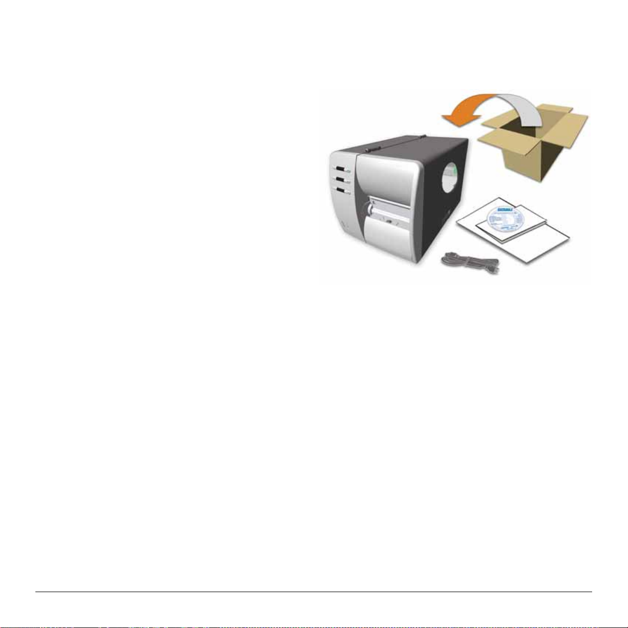
Inspecting the Printer
After removing the printer from the pa c kaging material, check the cont ents. The following items s hould be included:
Printer
Power Cord
CD-ROM and Docu mentation
Any special or a dditionally p urchased items.
Additional Requirements
The following items are necessary for generating labels from your printer. Contact your customer support or sales
representa tive for advice on which media a nd software may b es t be su ited for you r applica tion.
Serial, USB or Pa rallel cable
Ether net cab le for opt ional LAN connectivity
Applica ble Media
Applica b le S of tware
6 M-Class
Page 15
3.0 Introduction
This c hapter explains how to c onnect your printer, load media (and ribbon, if equip ped for t hermal trans f er).
3.1 Connecting the Printer
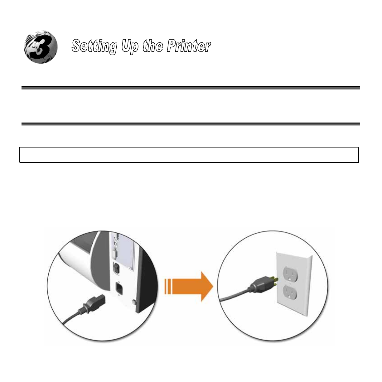
3.1.1 Power Connection
Note: When connecting the AC Power Cord or interface cables to the printer, ensure the Power On/Off Switch is in the ‘Off’
position.
1. P lace the printer on a fir m, level surface.
2. Ensure that the Power Switch on the Printer is in the ‘Off’ position.
3. Connect t he AC Power Cord to the rec ep tacle on the bac k of the Printer, a nd then plug the AC P ower Cord into a
properly grounded outlet. (The power supply automatically detects and then adjusts to the applied line voltage; see
Section 8.0 f or the a c c ep table voltage ranges. )
M-Class 7
Page 16
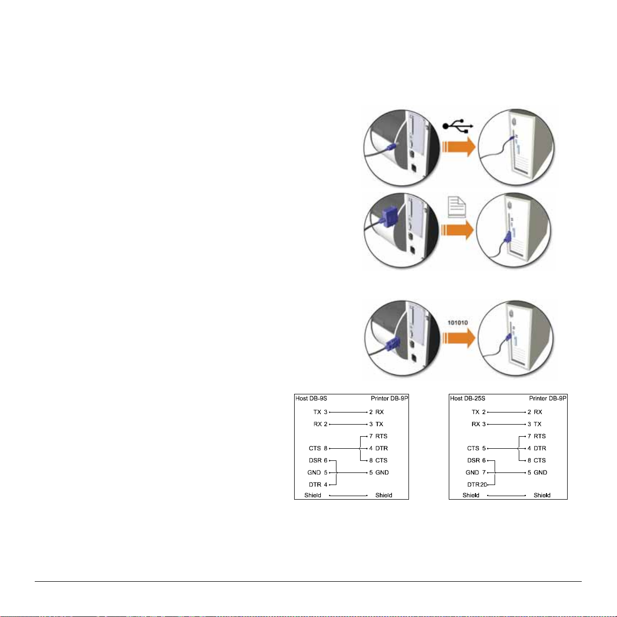
3.1.2 Interface Connection
The printer c an be connect ed to the host via a USB, s erial or pa rallel c able. The Pr inter will automati cally connect to the
first port (USB, serial or pa rallel) that transmits valid dat a. Af ter this connection has been made, the printer’s power must
be cycled ‘Off’ and ‘On’ to change the interface connection.
USB Connection:
The USB Interface is supported in Windows®95 and grea ter.
Depending up on the operating system of your host c omputer,
installat ion ma y dif fer slight ly.
Parallel Connection:
The parallel interface requires a Centronics® IEEE 1284 cable
with a 36 pin male connect or. Bi-direct ional mode is IEEE 1284
Compliant, using forward and reverse channel communications.
In this mode, data can be sent to the host provided it is also IEEE
1284 Compliant and has supporting software. Default is unidirectional, f or pr inters with front display, see C hapter 5.
Serial Connection:
The serial interface supports RS-232C
communicat i ons via a DB-9 connector. The
following list of serial por t sett ings is menuselecta ble and must match the host compu ter’s serial
port sett i ngs; see Chapter 4, f or non-disp lay printers
or C hapter 5 for display print ers.
• Baud Rate (Default 9600 bps)
• Word Length (Default 8 bits)
In addition to the port settings, the serial interface
cab le wiring must have specific connections (pinouts) for prop er dat a exchange between the host and
printer. The differ ent serial ca ble pin-outs a nd par t
numbers ar e in the following ta ble (contact you r
reseller for ordering information).
Optional Internal Ethernet Print Server:
(printers with front display only)
Part # 32-2483-01 Part # 32- 2301- 01
The printer is ava ilable with an optional Internal Ethernet Print Server. When using this connect ion please r ef er to
Appendix C or t he instructions inc l uded with the option for prop er setu p and configuration.
8 M-Class
Page 17
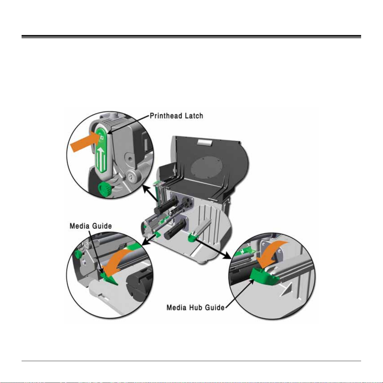
3.2 Loading Media
Load media int o the print er as f ollows :
1. Open the media cover and lower t he M edia Hub G uide and Media Guide.
2. P ress in on the Pr inthead Latch and raise the Printhea d Assembly.
M-Class 9
Page 18
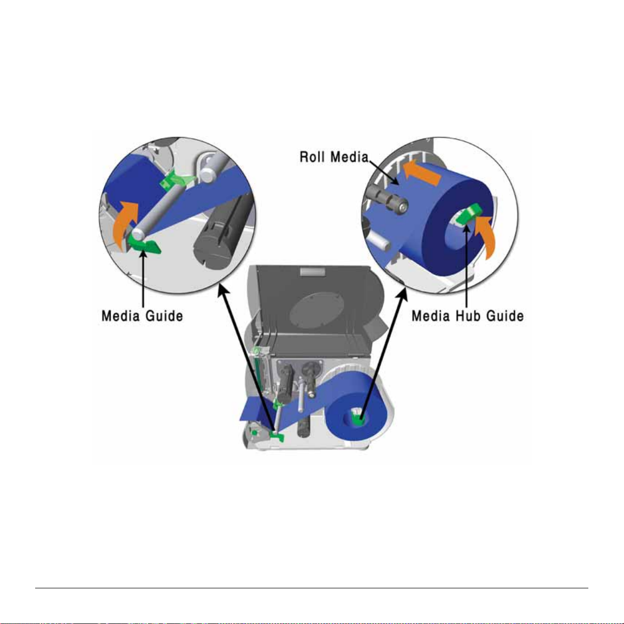
3. S lide the Roll Media onto the Media H ub and rais e the Media Hu b Guide. The Media H ub Gu ide s hou ld be pushed
inward so that it is ju st tou c hing the Roll Media.
4. R oute the Media thr ough the printer as s hown. Ra ise the Media Guide. The Media G uide should be p ushed inward so
that it is just t ouching the edge of the Media .
10 M-Class
Page 19
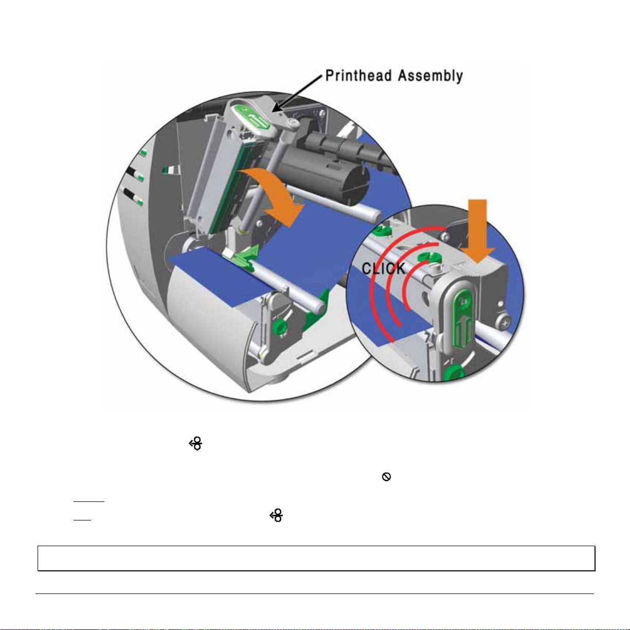
5. C lose the Printhead As sembly and press down until it locks into pla c e.
FEED
6. Close the cover and press the
If the p rinter does not correctly s ens e t he t op of each label, as denoted b y the
Printers without front display: Perf orm the Aut o Media Sensor C alibr ation, see sect ion 4.7.1.
Printers with front display: Pr es s and hold t he
but ton several times to position the media and ensure proper tracking.
ERROR
light, it may be necessary to:
FEED
but ton until at least one lab el gap or ma rk is advanced then
releas e. For additional calib rat i on procedures, see section 5.4
Note: The printer is fact or y set t o use 4-inch media (and ribbon, i f t hermal transfer equipped). When using a different width of
media/ribbon, please refer to section 6.2.
M-Class 11
Page 20
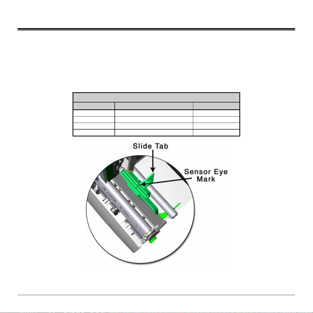
3.3 Medi a Sensor Adjustment
The Media Sensor needs to be positioned so that the printer can detect the presence of media and the top-of-form (except for
continuous stock, where the TO F is set throu gh the front panel.
To a dju s t:
With media loaded, as descr ibed in S ection 3. 2, gr as p t he Slide Ta b a nd move the Sens or E ye Mar k int o posit ion over
media according to the table below.
If loading media, ret urn to the media loading instruc tions.
Media Sensor Selection and Adjustment
Media Type
Die-cut Near the middle of the label Gap
Notched Centered over the notch Gap
Reflective Cent ered over the black mark Reflective
Continuous Near the middle of the media Continuous
Sensor Eye Mark Position
Sensing Required*
12 M-Class
Page 21
3.4 Loading Ribbon
Ribbon is requ ired with thermal trans f er media. It is r ecommended that the width of the ribbon be slight ly wider than the
media being used. Depending upon the type of Ribbon Supply Hub (see 3.4.1 for examples), the printer must use either
rib bons with the ‘coating side in’ or
Note: Using a ribbon that is slightly wider than your media (and liner, if any) will help protect against printhead wear.
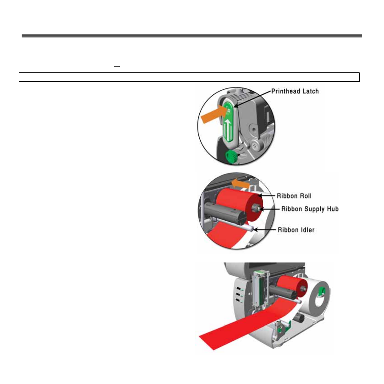
1. Open the media cover. Press in on t he Print head Latch
and ra i se th e pri n thead assemb l y .
rib b ons with the ‘ c oating s ide ou t’. To load:
2. Slide the Ribbon Roll onto the Ribbon Supply Hub until
it r es ts a gainst the hub’s flange. Ensure the r ibbon
unwinds in t he correct direct ion (see 3.4.1 f or
examples ) . Illus trations depi c t a ‘Coat ed Side In’
assembly.
3. R oute t he ribb on under the Ribbon I dler and t hen ou t the
front of the printer approximately 12 inches.
M-Class 13
Page 22
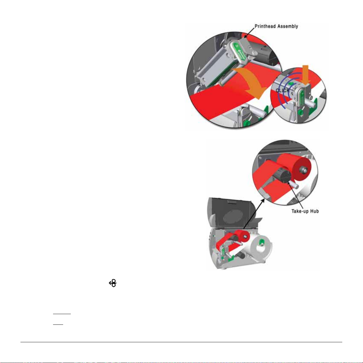
4. C l ose the Pr inthead Assembly and press down u ntil it
locks into p l ace.
5. Route t he ribbon up a nd then ar ound to the Ribbon
Take-Up Hub, winding it several times in a clockwise
direction to secure it in place.
FEED
6. Close the cover and press the
but ton several times t o position the ribbon and ensure proper tracking.
7. The ‘Media Type’ setting within the printer’s setup must be set to ‘Thermal Transfer’ to print using a ribbon;
Printers without front display: See section 4.5.2
Printers with front display: See section 5.1.2
14 M-Class
Page 23
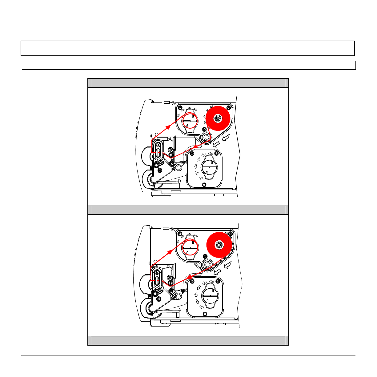
3.4.1 Ribbon Routing (Coated Side In & Coated Side Out)
Note: Directional Arrows near the Ribbon Supply Hub indicate the correct ribbon route. Ribbon types are available with the ink
(coating) layer wound ‘in’ or ‘out’. These types are NOT interchangeable for use with the printer.
Note: Ensure the inked side of the ribbon faces the media and NOT the printhead.
Ribbon Routing Diagrams
‘Coating Side In’ Ribbon Supply Hub
‘Coating Side Out’ Ribbon Supply Hub
M-Class 15
Page 24

16 M-Class
Page 25
4.0 Introduction
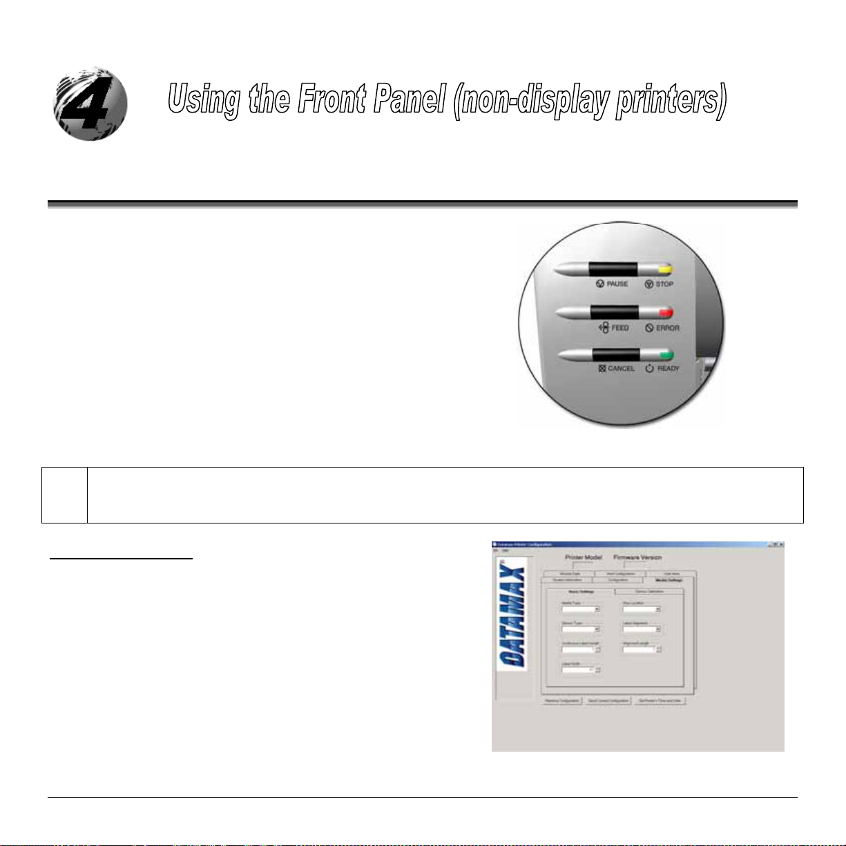
The Front Panel consists of three indica tor light s and t hree funct i on
but tons. The functions of t hes e light s and controls are listed in the
following sect ions.
4.01 DMXConfig
DMXConfig Features:
Simpli fy Printer Setup Process
Allows Real-Time Cont r ol/Query of Print er Configur ation
Defi ne and S ave Optimal Configur ations for Applications i.e.
Sav ed Configurations can be Shared with other P r inters and
Download Files, Format s and Fonts
Query Memory Modules
DMXConfi g (located on the M- c lass CD-R O M) is a windows ba sed configuration utility that c an simplify the
printer setup process. This application allows the user to make changes to the existing printer setup without using
the front panel but tons. Visit our website at www.datamaxc orp.com/soft ware/m-class / for the lates t releases.
Ribbon / Label S tock Combinations
Sent via Email
(sample screenshot)
M-Class 17
Page 26
4.1 Lights
(Normal power-up)
Normal Mode
STOP
ERROR
READY
Solid O n:
Flashing:
a label is presented to the operator.
Indicates a top of form or mechanical error has occurred
Solid On: Indicates the printer is on and ready for printing
Flashing: Indicates the printer is receiving data from the host
Indicates the printer is in the ‘Paused’ state
(When using the Peel & Present Option) Indicates
Both the
READY
and
STOP
Lights will b e on du ring power- up initialization and a warm res et .
4.2 Buttons
The three bu tto ns,
operationa l mode. The pr inter operat es in one of the following modes:
PAU SE
,
FEED
, a nd
Norma l : Normal printer functions. See Section 4.3.
Express Setup: Allows quick access to the most common printer settings, (Sensor Type, Media Type, and Option Control. See
Section 4.4.
Printer Setup: Allows changes to the printer’s operational settings. See Section 4.5.
Calibration: Allows the ‘calibration’ of the media being used for the correct sensing of the top of form. See Section 4.7.
CANCEL
perf orm different f unctions based on the pr inter’s
18 M-Class
Page 27
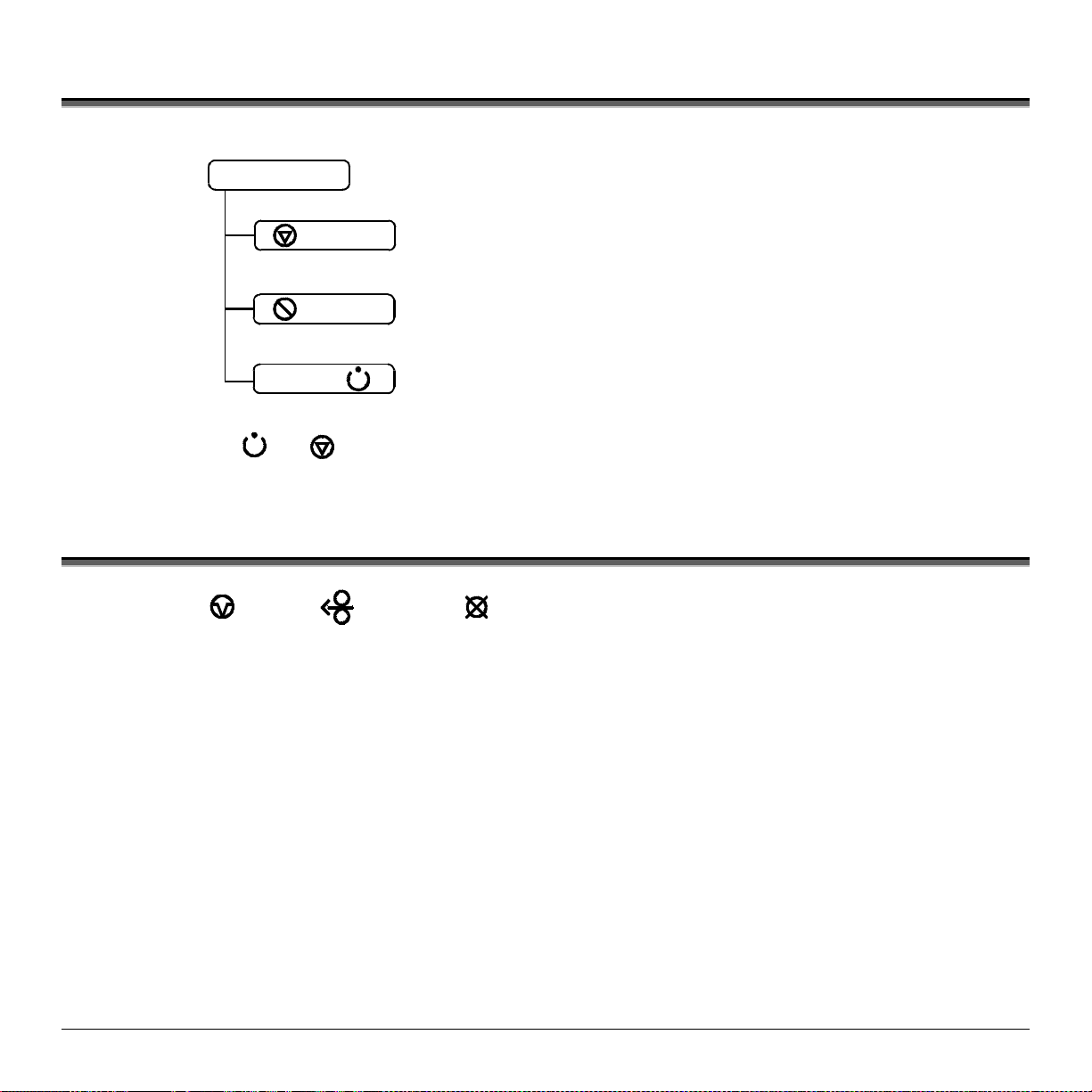
4.3 Normal Mode - Button Funct ions
In ‘Normal’ mode, t he p rinter ’ s buttons control normal oper ations such as pause, f eed, and ca nc el, as well as the t es t and
reset f unctions by using b utton c omb inations as detailed below.
(Normal power-up)
Normal Mode
PAU S E
FEED
Pauses/Un-pauses the printer
Feeds one label. Clears fault conditions
Press and Hold to perform “Label Alignment”, see section 4.6
Button Combinations (push buttons simultaneously)
PAU S E
PAU S E
FEED
+
+
+
FEED
CANCEL
CANCEL
CANCEL
Cancels the current batch of labels. Press the Pause button to
print the next batch of labels in the printer’s buffer
Prints the Test Label, see Section 4.8.2.
Performs a warm reset and returns to the Normal Mode of operation.
Produces Database Configuration an d T est Labels, see Section 4.8.1
M-Class 19
Page 28
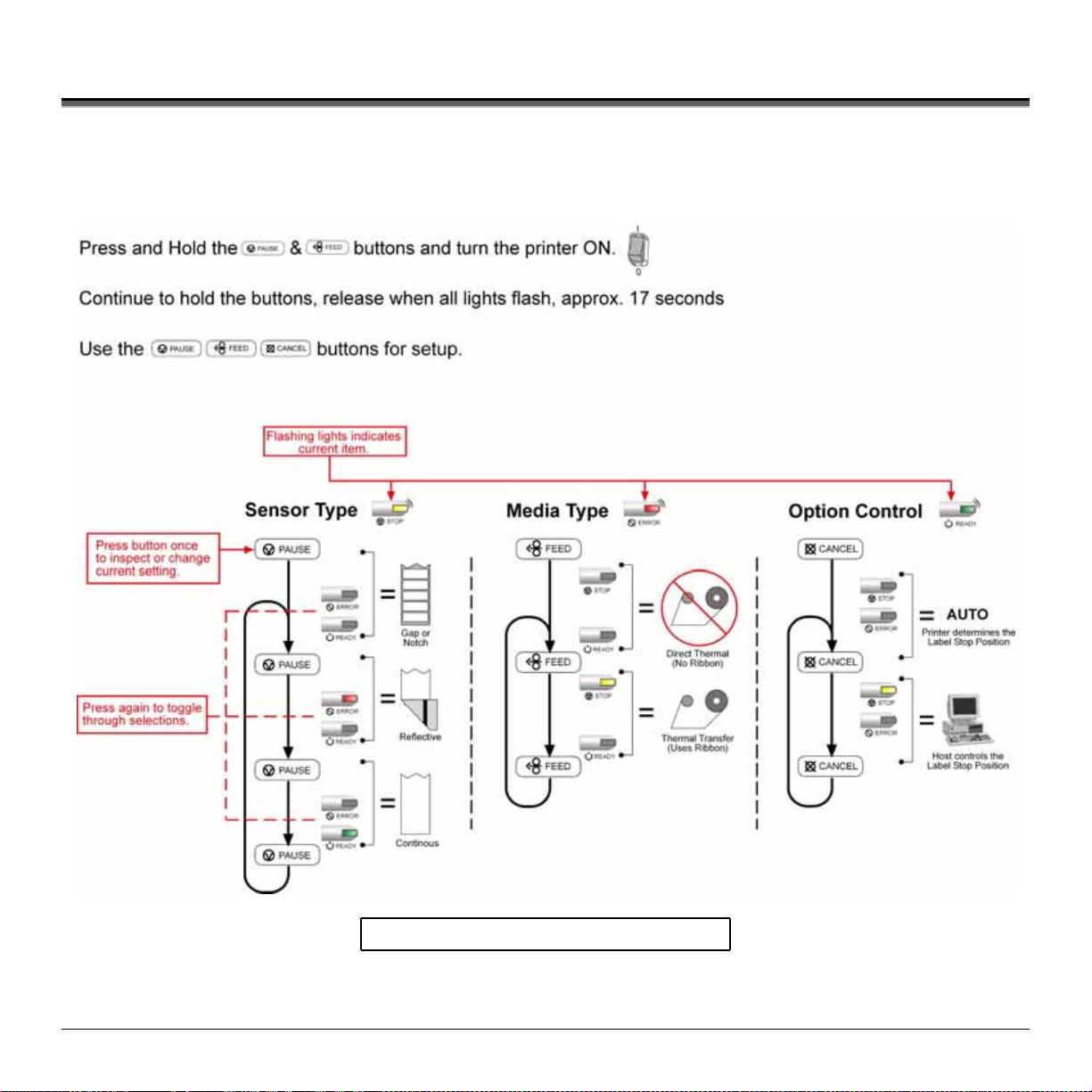
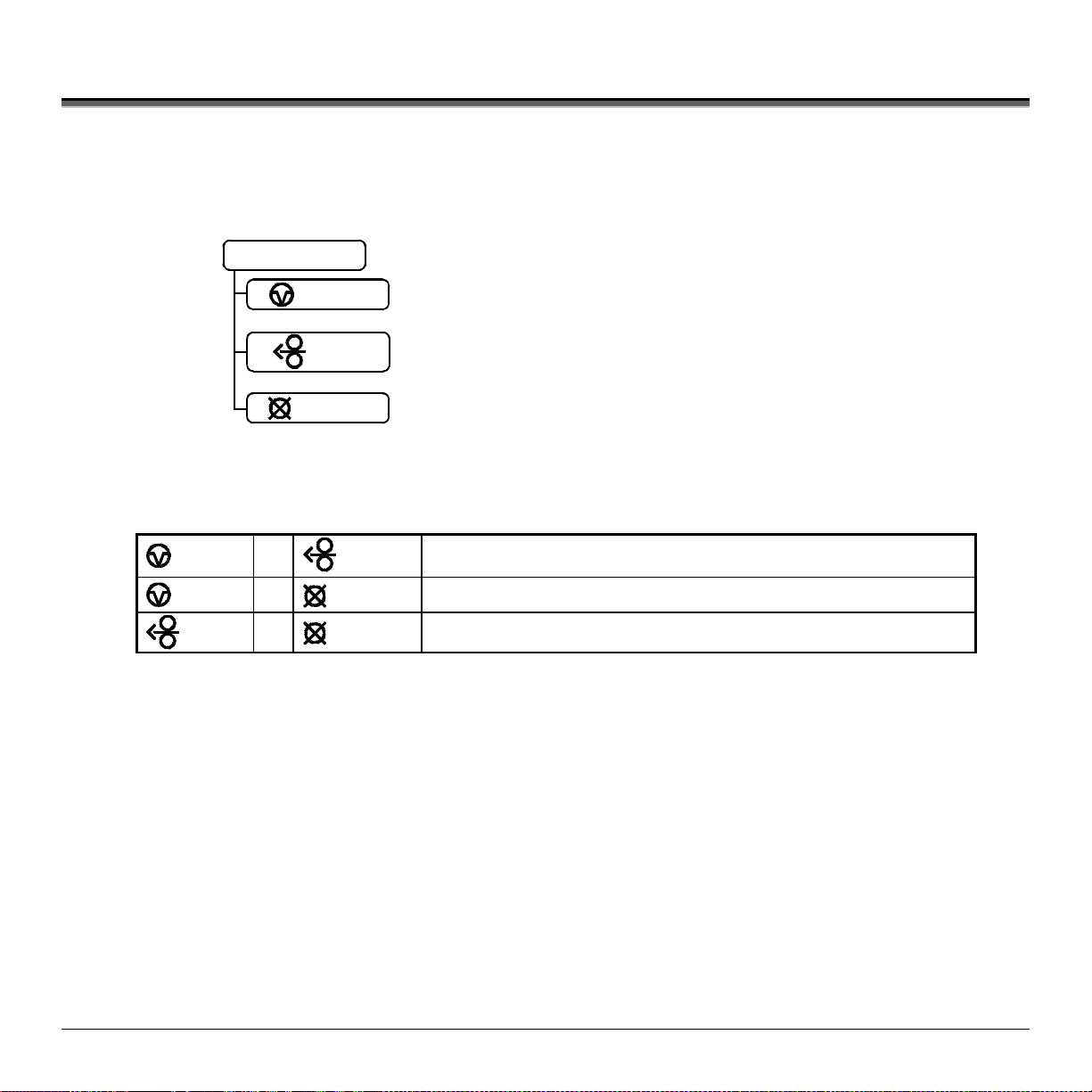
4.4 Expr ess Setup M ode - Button Functions
The Express Setup is a unique printer feature that allows users quick access to the most commonly used printer settings.
The selected setting is repres ent by a specific co mbina tion o f the pri n ter’s in d i cator l ights for ea ch of the three items,
(Sensor Type, Media Type, and Option Control). To enter the Express Setup…
T urn the printer OFF to save settings.
20 M-Class
Page 29
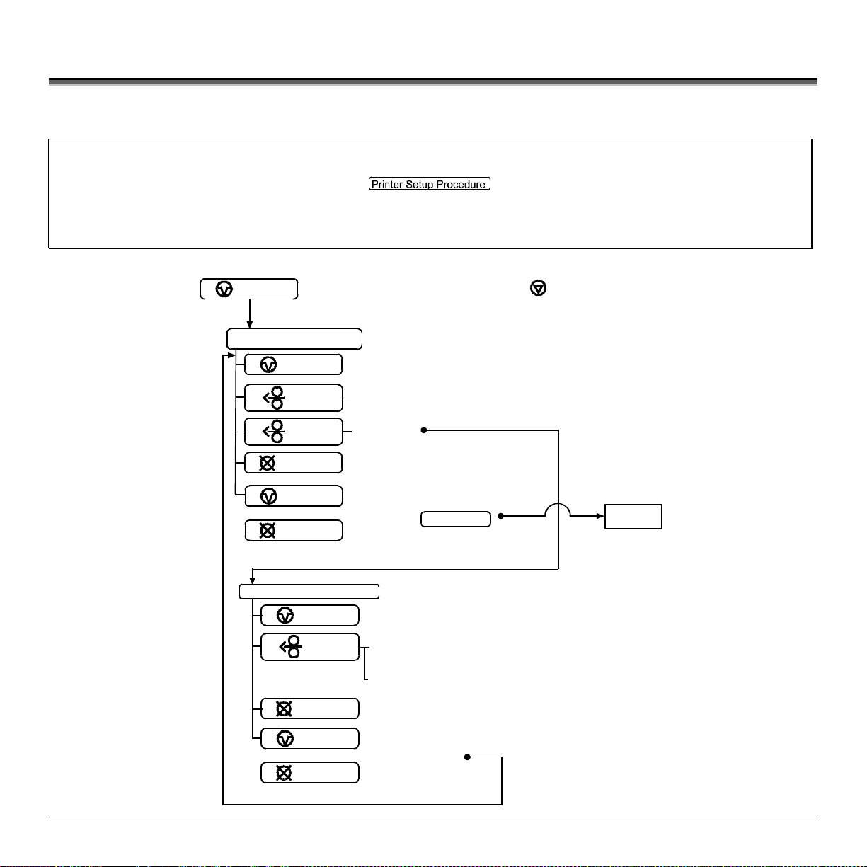
4.5 Print e r Setup Mode - But t on Func t ions
In ‘Printer Setu p’ mode, the buttons contr ol the sett ing of the printer’s opera tional it ems s uch as media settings ,
communicat i ons, a nd options as detailed below.
Notes: It is recommended that the Printer Setup Mode not be entered while in Peel Mode or with the optional Pr esent Sensor
Printer and cutter faults are disabled during
If at any time you wish to discard your changes and revert back to the previous values, simpl y t ur n of f power to the
If you wish to restore Factory Defaults see Section 6.7.
To change Printer Setup:
enabled. Depending on label size this can cause unpredictable results.
but can still occur while printing “test” labels.
,
printer.
PAU SE
(Press and hold during power-up until the light turns off)
Printer Setup Mode
STOP
PAU SE
FEED
FEED
CANCEL
PAU SE
+
Prints the ‘Printer Setup Menu List’, see section 4.5.1
Press and
(
Press and
(
Prints the ‘Test Label’ for “test”
Saves the current values
and resumes
CANCEL
Printer Setup Procedure
PAU SE
FEED
CANCEL
PAU S E
+
CANCEL
Feeds one label for “test”
Release
Increments item’s value
(
(
Decrements item’s value
Accepts the current
values for “test”
)
(Enters Printer Setup)
)
Hold
Normal Mode
(Current Item and Value is printed)
Press and
Release
Press and
Hold
Selects the next menu item
)
”Direct Select” menu item
)
eg. 7 Error light flashes = Baud Rate menu item #7
DONE
M-Class 21
Page 30
4.5.1 Printer Setup Menu List
The Printer Setu p Menu List la bel, shown b elow, contains the p rinter ’ s current values f or each menu it em that can be
modified via the front panel (See Section 4.5 .2 for a detailed item descri p tion.)
The Menu I tem Numbers c orres pond to the it em’s position in the Menu List for selection when pressi ng the
during the Printer Setup Procedure (see Section 4.5). For example to “ Dir ect Select” th e B AUD RATE Menu Item p ress
and hold the
FEED
but ton for 7 flashes of t he
ERROR
light and then releas e or for the TOF GAIN it em hold
for 12 flashes, etc.
FEED
but ton
FEED
Menu Item
Values
Numbers
1) DIRECT = MEDIA TYPE
2) EDGE = SENSOR TYPE
3) NO = PRESENT SENSOR
4) NO = CUTTER EQUIPPED
5) 127 = SOP ADJUST, 0.005 in.
6) 127 = PRESENT ADJUST, 0.005 in.
7) 9600 = BAUD RATE, bps
8) 8 = DATA BITS
9) STD = CONTROL CODES
10) 100 = CONT FORM LENGTH, 0.01 in.
11) 3 = OOS MAXV OLT, 0.1 Vol ts
12) 12 = TOF GAIN
13) 1 0 = TOF DELTA, 0.1 Volts
14) 0 = TOF LOW, 0.1 Volts
15) 426 = LABEL WIDTH, 0.01 in.
16) 6 4 = SCALABLE FONT, 4KB
17) 128 = INTERNAL MODULE, 4KB
18) NO = LABEL ALIGNMENT
19) 100 = ALIGNMENT LENGTH, 0.01 i n.
20) AUTO = OPTION CONTROL
21) DPL = INPUT MODE
22) STANDARD = DPL EMULATION
23) 10 = HEAT
24) NO = EXACT TIME
25) NO = GPIO
26) NO = NO REPRINT
Note: When using narrow media, t he ‘Menu Items’ colum n may be truncated.
Menu
Items
22 M-Class
Page 31

4.5.2 Menu Items and Values
The table below details the Print er Setu p Menu Li st items wit h a brief descr iption of t he it em’s f unction, and the p ossible
values . A “*” denot es the defau lt setting.
1) MEDIA TYPE
Sets printing for direct thermal (no
ribbon) or therma l transfer (r ibbon)
media.
Possible Values:
* DIRECT THERMAL
THERMAL TRANSFER
4) CUTTER EQUIPPED
Enables/Disables the optional
Media Cutter feature.
Possible Values:
* AUTO
NO
YES
7) BAUD RATE
Sets the serial port baud rate. (Must
match the host setting).
Possible Values:
600 to 38.4k; default = *9600 BPS
10) CONT FORM LENGTH
Sets the pag e ( label) s ize when th e
‘SENSOR TYPE’ is set to
continuous media.
Possible Values:
Range: 0 – 9999; default = *100
(Units = .01 inch)
2) SENSOR TYPE
Selects the sensor t ype used to detect
the media’s Top Of Form (TOF) mark.
Possible Values:
* EDGE: gap / notch TOF marks
REFL (Reflective): black marks
CONT (Continuous): no TOF marks
5) SOP ADJUST
Sets the start of print (SOP) location,
relative to the top of form.
Possible Values:
Range: 0 – 255; nominal = *128
(0 = close to edge; 255 = farthest from edge)
8) DATA BITS
Sets the serial data word length (Must
match the host setting).
Possible Values:
* 8
7
11) OOS MAXVOLT
Sets the media sensor level for the Out
Of Stock condition.
Possible Values:
Range: 0 – 16; nominal = *2
(Units = .1 volt)
3) PRESENT SENSOR
Enables/Disables the optional Present
Sensor feature.
Possible Values:
* AUTO
NO
YES
6) PRESENT ADJUST
Specifies an additional amount to feed
the label after printing.
Possible Values:
Range: 0 – 255; nominal = *128
(0 = close to edge; 255 = farthest from edge)
9) CONTROL CODES
Allows code selection listed in
Programmer’s manual.
Possible Values:
* (STD) Standar d Codes
(ALT) Alternate Codes
12) TOF GAIN
Sets media sensor Top of Form gain
value.
Possible Values:
Range: 0 – 15; nominal = *10
M-Class 23
Page 32

13) TOF DELTA
Sets the minimum media sensor
change requir ed to signify a label
gap or mark.
Possible Values:
Range: 0 – 50; nominal = *10
(Units = .1 volt)
16) SCALABLE F ONT
Sets the number of memory blocks
to allocate for scalable fonts.
Possible Values:
Range: 0 – 128; default = *64
(Units = 4K Bytes)
19) ALIGN LENGTH
Lead ing edge distance of two successive labels.
Must be entered if ‘LABEL ALIGNMENT’ is set
to Yes (see Section 4.6).
Possible Values:
0 – 999; default =100*
(Units = .01 inch)
14) TOF LOW
Sets the minimum media sensor
reading for paper (gap/notch) or mark
(reflective).
Possible Values:
Range: 0 – 50; nominal = *0
(Units = 0.1 volt)
17) INTE RNAL MODULE
Sets the number of memory blocks to
allocate for the internal RAM module.
Possible Values:
Range: 0 – 128; default = *128
(Units = 4K Bytes)
20) OPTION CONTROL
Sets label stopping (and in certain cases the starting) location for
different printer configurations.
Possible Values:
* AUTO (Automatically sets the stop location. Installed options
will be ‘auto-sensed’ and the appropriate stop position
will automatically be set. Host commands are ignored.)
HOST (Sets stop position according to options installed. If no
options are installed the printer sets stop location to the
next label’s start of print. Host commands will
override.)
15) LABEL WIDTH
Sets the label width.
Possible Values:
Range: 75 – 426; default = *426
(Units = .01 inch)
18) LABEL ALIGNMENT
Sets the label alignment method (see
Section 4.6)
Possible Values:
.
YES (user manually determines
‘ALIGN LENGTH’)
AUTO (prin ter determines ‘ALIGN
LENGTH’)
* NO (no Label Alignment
used)
24 M-Class
Page 33

21) INPUT MODE
Selects between the standard or template
interpretation of incoming data.
Possible Values:
* DPL (printer constructs the label using the
stand a rd DPL comman d s)
LINE (printer constructs the label using a
preloaded template form)
23) HEAT
Controls the ‘burn-time’ of the printhead. This is
the equivalent of Heat Setting on most label
software programs.
Possible Values:
Range: 0 – 30; default = *10
25) GPIO
Sets the printer’s option port to function for GPIO
applications, (see Appendix F for more
information).
Possible Values:
YES or NO; defaul t = *NO
22) DPL EMULATION
This instructs the firmware to process specific DPL data (Start of
Print, DPI, and Imaging function) according to the selected
printer emulation.
Possible Values:
* STANDARD
ALLEGRO (Allegro Emulation)
P PLUS (Prodigy Plus Emulation)
PRODIGY (Prodigy Emulation)
24) EXACT TIME
Instructs the printer to wait until the system is idle before the next
label’s data and time fields are formatted to eliminate any
discrepancy between the buffered and printed times.
Possible Values:
YES or NO; defaul t = *NO
26) NO REPRINT
When a fault condtions is detected, printing stops and the ERROR
light turns on. After the problem is corrected, the FEED Key must
be pressed to clear the fault. The label in process is not reprinted.
Possible Values:
YES or NO; defaul t = *NO
(NO = NO REPRINT” disabled, reprinting will occur.)
Note: All of the menu items listed in t he previous section are stored in non-volat i le memory.
M-Class 25
Page 34

4.5.3 Step by Step Modification of the Printer Setup
The following is an example of Print er Setup modification. Alt hou gh this exa mp le will detail how to modify the ser i al Bau d
Ra te, the s ame method can be u sed to cha nge any of the printer ’s menu item settings.
Note: It is recommended that the Printer Setup Mode not be entered while in Peel Mode or with the optional Present Sensor
1. With printer ‘Off’ and properly loaded with media, press a nd hold the
2. Press and hold the
enabled. Depending on label size this can cause unpredictable results.
STOP
Continue to hold the bu tton until the
FEED
but ton and count 7 f l ashes of the
light tu rns off, then relea se it.
should b e p roduced:
PAU S E
but ton while powering ‘ On’ the printer .
ERROR
light, then release it . The following printou t
3. Press the
PAU S E
button one time to increment to the 19200 bps value. The following printout should be produced:
4. At this point you will accept the current values for “t es t” and exit the Printer Setup Procedu re by simult aneously and
briefl y press i ng the
PAU S E
Note: If you wish to discard your changes and revert back to the previous values simply turn off power to the printer before
Step 5.
5. N ow you can save your cha nges and res ume by simultaneously and briefly pressing the
CANCEL
but tons. W ait until the
CANCEL
+
but tons. W ait until the
STOP
light goes off .
STOP
light goes off .
PAU S E
+
26 M-Class
Page 35

6. To confirm that your changes have b een made p ress the
FEED
+
CANCEL
but tons simult aneously, this will pr int the
Database Configuration Label. The label should show the new Baud Rate value of 19200.
Label 1
WED NOVEMBER 10, 2003 21:41:31 323
VER: M4206 - 05.08 11/07/03
BOOT 83-2383-05E
CODE 83-2385-05H
FPGA 83-2384-05B
FONT 83-2460-01C
UMOD 83-2472-01A
256K FLASH MODULE B
SYSTEM FLASH SIZE_____2 MBYTES
SYSTEM RAM CHECKS____ GOOD
SYSTEM RAM SIZE___ 4096 KBYTES
SYSTEM RAM AVAIL__ 3180 KBYTES
AUTO DETECTION
CUTTER____________NOT DETECTED
PRESENT SENSOR____NOT DETECTED
CURRENT STOP LOC__TEAR
EXPRESS SETUP
MEDIA SENSOR______EDGE
PRINT METHOD______TRANSFER
OPTION CONTROL____AUTO
INPUT VALUES
PAPER_____________ 207
POT_______________ 33
TRAN______________ 157
REFL______________ 0
RIBN______________ 237
TEMP______________ 64
VOLT______________ 218
PRESENT SENSOR____ 0
COUNTER INFORMATION
ABSOLUTE VALUES 7-16-2003
LENGTH____ 773 INCHES
TIME______ 20 HOURS
RESETTABLE VALUES 7-16-2003
LENGTH____ 969 INCHES
TIME______ 56 HOURS
MEMORY CONFIGURATION
INTERNAL MODULE A______ 128
SCALABLE FONTS_________ 64
LABEL SIZE 0426:10912 IN
CONFIGURATION
SERIAL PORT SELECTED
19.2; 8BITS
EDGE
MEDIA TYPE________ TRANSFER
CONT FORM LENGTH__ 0
PRESENT ADJUST____ 128
SOP ADJUST________ 128
TOF LOW___________ 0 0
TOF DELTA_________ 10 10
TOF GAIN__________ 7 5
OOS MAXVOLT_______ 3 2
LABEL ALIGNMENT___ AUTO
ALIGN LENGTH______ 611
OPTION CONTROL____ AUTO
INPUT MODE________ DPL
DPL EMULATION_____ STANDARD
HEAT______________ 10
EXACT TIME________ NO
GPIO______________ NO
NO REPRINT________ NO
SYMBOL SET________ PM
FONT SUBSTITUTION_ NONE
IGNORE COMMANDS
SYMBOL SET SELECT_ NO
CNTRL CODES_______ NO
HEAT______________ NO
SPEED_____________ NO
SOP OFFSET________ NO
Label 2
M-Class 27
Page 36

4.6 Label Alignment
The Label Alignment function is intended for use when the la bel length is less than the dis tance between the print head and
the media sensor or where label waste at power-up is a concern. L abel Alignment (s ee table below) is not r ec ommended for
label lengths grea ter than 6. 5 inches or f or media cont aining 2 or more form lengths.
Label Stock Label Alignment Setti ng
Continuous NO
6.5 inches or less YES or AUTO
6.5 inches or more NO
Multiple length labels NO
The Label Alignment func tion is chos en via the menu system (see Section 4.5) or by host commands. The three poss ible
modes, YES, AUTO, and NO, are detailed in t he following sections .
4.6.1 Label Alignment = YES
In this mode, the operator must supply an ‘ALIGN LENGTH’ value.
This value must be physically measu red from leading edge to lea ding
edge of two suc c essive labels, as shown. The meas urement must be as
accurate as possible. For very short labels, errors as small as 0.01” can
resu lt in noticeable print var i ations on the labels between the media
sensor and t he p rinthea d.
The measured v alu e must be s en t to the printer v i a t h e h ost compu ter o r
entered using the Printer Setup Mode (see Sec tion 4.5).
FEED
Then, in N ormal M ode, pres s and hold t he
seconds). The printer will align the lab el to the top of f orm positi on.
Note: If m edia wit h a different label length is subsequently loaded, the ‘ALIGN LENGTH’ must be recalculated and re-entered.
button (about 4
28 M-Class
Page 37

4.6.2 Label Alignment = AUTO
In this mode, the print er automatically calc ulates the ‘ALIGN LENGTH’ t hu s eliminating the need to physically meas ure
the label. This mode is usu ally pr eferred in a pplica tions that r equ ire frequent media changes to labels of dif ferent lengths .
FEED
To p erform an Auto Alignment, in Normal Mode press and hold the
but ton (ab out 4 seconds). The pr inter will feed
labels to calcu l ate the la bel length. Following the calcu lation, the print er will save t he meas urement and align to the t op of
form position. Auto Alignment ca n result in wasted labels during t he measurement p rocess (the longer t he label length the
greater t he waste).
Auto Alignment with the Present Sensor enabled:
If the printer is equipped wit h the Pres ent Sensor option a nd that f eature is enabled, while the label length is calc ulated t he
printer will pa use and illu mina te the
STOP
light after each movement. The op erat or must pres s the
PAU S E
button for the
alignment to c ontinue. This a llows the operator to r emove any labels a s required; however, labels s hould not be forcibly
removed since they may not actually be posit ioned f or removal, but at an inter im p osition r equ ired for mea surement.
4.6.3 Label Alignment = NO
When Lab el Alignment is not enabled (i.e., set to N O ) , pr inting begins at the curr ent label p osition without a lignment,
assuming the lab el is at t he start of print p osition. Additionally, if the label length is short , lab els between the print head and
the media sensor may be u nused.
M-Class 29
Page 38

4.6.4 Label Alignment Troubleshooting
If you experience lab el alignment problems, the following table offers p ossible causes and solutions.
Proble m Possible Cause Solution
Attempting to perform
Label Alignment results
in no paper movement.
First label is wasted
during alignment. All
labels thereafter print to
the correct start of print
position.
With th e Presen t Sensor
enabled, Label Alignment
cannot be performed
without a Label Length.
Alignment Length is too
long.
~OR~
For labels whose length
and stop position cause
them to stop between
labels on the media
sensor, the alignment
function can result in
wasted labels.
Set Label Alignment to AUTO, press and hold
media moves for the automatic length measurement.
~OR~
Re-measure the Label Alignment Length. Use Printer Setup
mode to enter the new length. Print a Database Configuration
label to ensure the new length has been set.
Set Label Alignment to AUTO, press and hold
paper moves for automatic Label Alignment length
measurement.
~OR~
Re-measure Label Alignment Length, use Menu Setup to set
new length, ensure desired length has been set.
Obtain a slightly different label Alignment Length
measurement. Using the Label Alignment AUTO mode, hold
FEED
the
measurement. Ensuring slack in the label stock may result in a
slightly different measurement. The Alignment Length may
also be set manually via the Setup Menu. Increasing or
decreasing the value by 1 or 2 units (in . / 100) m ay help to
prevent the wasted labels; however, this may result in incorrect
print positions for labels that are short in length.
button to force an alignment and label
FEED
FEED
until
until
Label Alignment is
incorrect . Press ing
FEED
successively
results in a short label
length, one-inch.
Label Alignment Length
is n ot correct . Th e
default Label Alignment
Length is 1.00”, and will
result in this behavior
when any larger label
length is used without
setting the appropriate
FEED
Set Label Alignment to AUTO. Press and hold
until
paper moves for automatic Label Alignment Length
measurement.
~OR~
Measure the label length and use the Setup Menu to set the
new length. Print a Database Configuration label to ensure the
new length has been set.
length.
30 M-Class
Page 39

Problem Possible Cause Solution
Label Alignment is
incorrect . Press ing
FEED
successively
results in a label length
longer than actual, oneinch.
Tear Mode is selected
but the label stop
position (present
position) is not far
enough forward.
Tear Mode is selected
but the label stop
position (present
position) is too far
forward.
The
ERROR
light
illuminates during label
alignment.
Label Alignment Length
is n ot correct . Th e
default Label Alignment
Length is 1.00”, and will
result in this behavior
when any larger label
length is used without
setting the appropriate
Set Label Alignment to AUTO. Press and hold
paper moves for automatic Label Alignment length
measurement.
Measure the label length and use the Setup Menu to set the
new length. Print a Database Configuration label to ensure the
new length has been set.
length
Another present position
has been determined.
Enabling the Present
Sensor causes the label
stop position (present
position) to be
approximately 0.1”
behind the peel bar.
~OR~
The P resent Adjust value
is n ot correct .
Disa bl e the Present Sensor.
Ens u re the host computer is not pr oviding a Present Di s tance
shorter than is required for the Tear Bar.
Use the Setup Menu to modify the Present Adjust value.
Another present position
has been determined.
~OR~
The P resent Adjust value
is n ot correct .
The label supply is empty Load media.
En s u re the host com puter is not p roviding a P resent Dist ance
longer than is required for the Tear Bar.
Use the Setup Menu to modify the Present Adjust value.
~OR~
~OR~
FEED
until
M-Class 31
Page 40

4.7 Calibration M ode – But t on Func t ions
In ‘Calibr ation’ mode, the buttons a llow the printer to adjust to the media b eing u sed. Calibr ation can be performed either
automatically or manually, as detailed below.
Notes: Before calibrating, ensure that the Printhead Carrier Assembly is lat ched down, that t he cover is closed, and that t he
Printer and cutter faults are disabled during
If at any ti me you wish to discard your changes and revert back to the previous calibrati on si mply turn of f power to the
To perform Calibration:
media sensor has been set for the appropriate media type, see Section 4.5.2.
and
printing “ t est” l abels.
printer. Also, Fact or y Default s can be restored, see Section 6.7
CANCEL
(Press and hold during power-up until the light turns off)
STOP
Calibration Mode
PAU SE
, but can still occur while
Auto Media Calibration
FEED
FEED
CANCEL
PAU SE
+
Press and
(
Release
Press and
(
Prints the ‘Test Label’ for “test”
Saves the current values
and resumes
CANCEL
Media Sensor Calibration
PAU SE
FEED
CANCEL
PAU SE
+
CANCEL
(See section 4.7.1)
Feeds one label for “test”
)
(Until Paused light turns off)
)
Hold
Normal Mode
(See section 4.7.2)
Analyze for ‘Paper’
Analyze for ‘Backing or ‘Mark’
Analyze ‘Out of Media’ condition
Accepts the current
values for “test”
DONE
32 M-Class
Page 41

4.7.1 Auto Media Sensor Calibration
Auto M edia Sensor Ca libration a u tomatic ally establishes the optimum sens ing values for the media you are using in the
printer.
Note: Before calibrating, be sure the media sensor is set for the appropriate m edia ty pe, see Section 4.5.2; also, ensure that the
Printhead Carrier Assembly is l at ched down and the cover is closed.
To automatically calibrate the media sensor:
1. With the desired media loaded, hold the
STOP
until the
light tu rns off then release it .
CANCEL
but ton while powering up the printer. C ontinue to hold t he b utton
PAU S E
2. Next press the
but ton. The printer will feed approximately ten inches of media to calculate the TOF Delta
and Low values to be used.
3. Upon c omplet i on, one of the following lights will flash five times to denot e t he result of the auto calib ration attempt:
STOP
Note: If you wish to discard the changes and revert back to the previous calibration si mply turn off the printer before Step 4.
light = Successful calibr ation. Pr oc eed to Step 4.
ERROR
light = Uns uccess f ul calib ration, t ry again. If the calibration continu es to fail proceed to Section 4.7.2.
4. N ow save th e changes a nd resu me
briefly. Wait until the
STOP
light goes off .
by pressing the
PAU S E
CANCEL
+
but tons simultaneously and
M-Class 33
Page 42

4.7.2 Manual Media Sensor Calibration
The Manua l Media S ens or Calibration p rocedure should be u sed in cas es where the pr inter continues to suffer from media
sensing problems a fter performing or attempti ng to perf orm the Auto Media S ens or Calibr ation (see Section 4 .7. 1).
Note: Before calibrat i ng, be sure the media sensor is set for t he appropri at e m edia ty pe, see Section 4.5.2; also, ensure that the
Printhead Carrier Assembly is l at ched down and the cover is closed.
To manu ally calibrate the media sensor:
1. Hold the
releas e the button. Nex t, p ress and hold the
CANCEL
but ton and p ower-up the printer. Continue t o hold the but ton until the
FEED
but ton, continue to hold t he b u tton until the
then release the button.
2. R emove all the mater ial fr om t he media s ensor, ( see Section 3 .3 for the sensor’s loc ation) , close t he P rinthea d Carrier
Assembly, and then press the
CANCEL
but ton. The printer will flash the
ERROR
light as it analyzes the no media
condition.
3. P osition t he b acking mat erial or the black (reflective) mark in the media sens or, cl ose the Printhead Car rier Assembly,
and then p ress th e
FEED
but ton. The printer will flash the
ERROR
light as it analyzes the top of form mark.
4. Place t he media with the ba c king att ached (if any) in the media s ensor, c l ose the Printhead Car rier Assembly, and then
press the
PAU S E
but ton. The printer will flash the
ERROR
light as it analyzes the material.
5. Simultaneously and briefly press the
PAU S E
CANCEL
+
buttons to accept the calibration for “test” and exit the
. One of the following lights will flash five t imes to denote the res ult of t he manual calibr ation
attempt:
STOP
light = Successful calibr ation. Pr oc eed to Step 6.
ERROR
light = Uns uccess f ul calibra tion. Retry the procedu re beginning at St ep 1 .
FEED
6. Use the
Note: If you wish to discard the changes and revert back to the previous calibration simply turn off the printer before Step 7.
but ton (feeds a label), and the
CANCEL
button (prints a test label) to test the current calibration.
7. N ow save th e changes a nd resu me
briefly. Wait until the
STOP
light goes off .
by pressing the
PAU S E
CANCEL
+
but tons simultaneously and
STOP
light tu rns off ; then
STOP
light tu rns on;
34 M-Class
Page 43

4.8 Internal Labels
The following s ection details the pr inter’s interna lly gener ated configura tion and t es t lab els .
4.8.1 Database Configuration and Test Labels
The Data b ase Configuration Label provides valuable p rinter inf ormation inc l uding the fir mwa re version, memory
allocations, enabled op tions, and label-counter dat a.
To print the Database Configuration and Test Labels:
With the printer on, loaded with media (at least 4 inches wide) and ribbon (if printing with thermal transfer media), press
the
FEED
+
CANCEL
buttons simultaneously.
The first label pr inted will be the Dat aba se Configurat ion Label.
Label 1
WED NOVEMBER 10, 2003 21:41:31 323
VER: M4206 - 05.08 11/07/03
BOOT 83-2383-05E
CODE 83-2385-05H
FPGA 83-2384-05B
FONT 83-2460-01C
UMOD 83-2472-01A
256K FLASH MODULE B
SYSTEM FLASH SIZE_____2 MBYTES
SYSTEM RAM CHECKS____ GOOD
SYSTEM RAM SIZE___ 4096 KBYTES
SYSTEM RAM AVAIL__ 3180 KBYTES
AUTO DETECTION
CUTTER____________NOT DETECTED
PRESENT SENSOR____NOT DETECTED
CURRENT STOP LOC__TEAR
EXPRESS SETUP
MEDIA SENSOR______EDGE
PRINT METHOD______TRANSFER
OPTION CONTROL____AUTO
INPUT VALUES
PAPER_____________ 207
POT_______________ 33
TRAN______________ 157
REFL______________ 0
RIBN______________ 237
TEMP______________ 64
VOLT______________ 218
PRESENT SENSOR____ 0
COUNTER INFORMATION
ABSOLUTE VALUES 7-16-2003
LENGTH____ 773 INCHES
TIME______ 20 HOURS
RESETTABLE VALUES 7-16-2003
LENGTH____ 969 INCHES
TIME______ 56 HOURS
MEMORY CONFIGURATION
INTERNAL MODULE A______ 128
SCALABLE FONTS_________ 64
LABEL SIZE 0426:10912 IN
Label 2
CONFIGURATION
SERIAL PORT SELECTED
19.2; 8BITS
EDGE
MEDIA TYPE________ TRANSFER
CONT FORM LENGTH__ 0
PRESENT ADJUST____ 128
SOP ADJUST________ 128
TOF LOW___________ 0 0
TOF DELTA_________ 10 10
TOF GAIN__________ 7 5
OOS MAXVOLT_______ 3 2
LABEL ALIGNMENT___ AUTO
ALIGN LENGTH______ 611
OPTION CONTROL____ AUTO
INPUT MODE________ DPL
DPL EMULATION_____ STANDARD
HEAT______________ 10
EXACT TIME________ NO
GPIO______________ NO
NO REPRINT________ NO
SYMBOL SET________ PM
FONT SUBSTITUTION_ NONE
IGNORE COMMANDS
SYMBOL SET SELECT_ NO
CNTRL CODES_______ NO
HEAT______________ NO
SPEED_____________ NO
SOP OFFSET________ NO
M-Class 35
Page 44

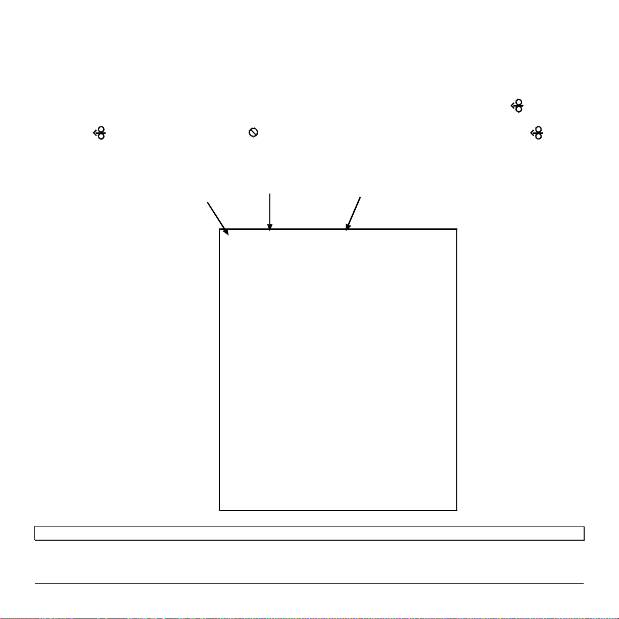
The second label pr inted is the Test Label. This label is us ed to test the condition of t he p rinthea d, as shown below:
Good Print Quality Label:
Even pattern consistency
indicates correct printhead
operation.
Faulty Prin t Quality Label:
Streaks indicate a dirty or
faulty printhead. See Section
6.1 for cleaning instructions.
36 M-Class
Page 45

4.8.2 Test Label
The T es t Label is used t o evaluate the cur rent printer setup f or pr int qua lity, la bel tracking, and pr int positioning.
To print the Test Label:
With the printer loaded with media (at least 4 inches wide), and ribbon (if printing with thermal transfer media),
simultaneously press the
PAU S E
FEED
+
but tons.
M-Class 37
Page 46

38 M-Class
Page 47

5.0 Introduction
Controlling Printer Settings with the Internal Printserver
If your pr inter is equ i p ped with the optional I nternal Print server , many of t he p rinter ’ s setting and parameters can be
modified and controlled via t he b uilt-in H TML pages resident in t he p rinter . Thes e p ages can be accessed us ing any web
browser b y simply enteri ng the IP address in the URL ba r.
The front panel is compr i sed of thr ee indicator lights, a Liqu id Crys tal Display and five mode-dependant keys . The
selectable modes (Rea dy, Menu and Quick Test ) and the r elated func tions of the printer keys are detailed below.
Note: To Adjust the LCD contrast, pr ess and hold the
MENU
key for 10 to 20 seconds to modify the LCD contrast level.
5.0.1 Ready Mode:
Normal Operation (Ready Light ‘On’)
The PAUSE Key temporarily suspends printing. Pressing it again will return the printer to normal
operation.
The F EED Key advances one label, and cl ears any corr ected faul ts.
Pressing and holding causes the printer to perform a Quick Media Calibration; see Section 5.4.1.
The CANCEL Key ‘pauses’ the printer and then prompts you for confirmation. If yes, the current
job is cancelled. The printer remains paused.
Pressing and holding four seconds will reset the printer and clear temporary host settings (soft
reset).
MENU
The ME NU Key toggles between the Ready and Menu Modes. I n the Ready Mode, pressing a nd
holding four seconds will change the display contrast.
The TEST Key enters (or exits) the Quick Test Menu.
M-Class 39
Page 48

5.0.2 Menu Mode: Configuration (Ready Light ‘Flashing’)
REV
The LE FT ARR O W Key s cr olls to t he pr eviou s menu it em on the same menu level. It
also decrements numerical valu es in mos t menu selections.
FWD
The RI GHT ARRO W Key scroll s t o the next menu item. It also inc rement s numerical
values in most menu selections.
The EN TE R Key s elects t he funct ion, it em or disp layed va lue. It als o moves between
selections wit hin multiple pa rameter f ields .
The E SCAPE Key moves to the pr evious menu level, and fina lly back t o the Ready
Mode.
When a pr int job is in p rogress , pres sing the TES T Key will terminate the job. The
printer will prompt you for confirmation; if ‘Yes,’ the curr ent job is cancelled and
then Menu M ode is restored.
40 M-Class
Page 49

5.0.3 Quick Test Mode: Print Test Labels
Note: The Quick Test Mode functions are disabled while processing data from communications interfaces until the Host Timeout
value expires.
REV
The LEFT ARROW Key scrolls to the previous test function.
FWD
The RIGHT ARRO W Key scrolls to the next tes t function.
The ENTER Key will cha nge the select ed test la b el qua ntit y of 2, 100, 1000, or 9999
(except the ‘Configuration Label’, quantity of one). Holding down the key scrolls
quantities.
The ESCAPE Key will exit the Qu ic k Test Mode without print ing.
The T EST K ey will print the selected t est label a t the selected qua ntity. D uring test
label p rint ing, t his key a lso fu nctions as a c ancel key (t he print er will prompt you for
confirmation before cancellation occurs ) .
You can program a time delay between the printing of test labels using the ‘Print Test Rate’ featur e; see Section 5.1.7
M-Class 41
Page 50

5.0.4 Indicator Lights
5.0.5 LCD
‘On’ indica t es tha t t he pr int er is p owered ‘O n’ a nd, a ft er initia liz a tion, it indica t es t he
Ready Mode.
‘Slow Flashing’ indicates Menu Mode.
‘Fast F lash ing’ indicates d ata i s bei ng r eceived an d processed .
‘On’ indicates a ‘Paus ed’ c ondition.
‘Slow Flashing’ indicates a Warning. ‘Fast Flashing’ indic ates a F ault. See Section
7.1 for a listing of associated messages.
Liquid Crystal Display
The disp lay provides several types of information:
• Following a b rief power -up s equ ence (initialization), the ‘R eady’ message.
• The time a nd da te, if t he pr int er ha s r eceived it fr om one of the following: the host,
the fr ont pa nel s etting, or the T i me and Dat e op tion.
• A label counter during a batch print job.
• The Menu System when in Menu Mode.
• Any promp t, condition, downloading, wa rning, or fa ult message.
42 M-Class
Page 51

5.1 The Menu System
Printer operation can be controlled through the user interface, allowing the operator access to these six menu system
branches:
• Media Settings
• Pr int Control
• Printer Options
While in the menu syst em, the cu r r ent s election will b e indica t ed with a n a st er is k (*) next to the displa yed item on the LCD.
Selections designated with a section symbol (§) will require a printer reset before becoming effective. A reset will be
aut omatically invoked when exit ing the menu sys tem and answer ing ‘Yes’ to the ‘Save Cha nges’ pr ompt. Cha nges made
will be saved. When power is removed, the new setti ngs will be restored up on power-up .
The same functional commands from your host computer may, in some cases, override the printer’s menu settings. In
additi on, as a secur ity feat ure for the prevention of accidenta l or una uthor ized changes, the menu system ha s a pa ssword
protection f eature.
Note: In the following subsections, the factory default settings are denoted with the ‘’ symbol. Selections denoted with a
diamond (♦) can only be changed t hrough the menu system - all other selections can be overridden by host software
commands. Consult the Class Series Programmer’s Manual for specific information.
5.1.1 Entrance and Exit Prompts
With ‘Ready’ dis played on the L CD, press the
Note: While in Menu Mode, the printer will stop p rocessing new D PL (or bitmapped) data.
MENU MODE
ENTER PASSWORD
0 0 0 0
KEEP HOST CHANGES?
ENTER = YES
SAVE CHANGES?
ENTER = YES
• System Settings
• Communications
• Diagnostics
MENU
Key to ent er Menu M ode.
Depending up on the conf igur at ion of the p rint er, the following E ntr anc e and Ex it P rompt s
may be disp layed when acces sing or lea ving the Menu S ystem.
You a re a tt empting t o enter Menu Mode. Secu rity ha s been ena bled and now t he corr ect
user - def inable password is r equ ired before access ing the Menu Mode functions .
You are now entering Menu Mode. Existing Host commands have affected the
configuration of the printer. Pressing ENTER will save these changes; otherwise, the
printer will revert to p reviously s aved sett i ngs.
You are now exiting Menu Mode, but have made changes to the printer’s settings.
Pr essing ENT ER will reconf igure your printer accor ding to these cha nges; otherwis e, the
printer will revert to p reviously s aved sett i ngs.
Note: If changes have been made that require a reset, the printer will automatically invoke that reset.
M-Class 43
Page 52

5.1.2 Media Settings
MEDIA TYPE
DIRECT THERMAL
THERMAL TRANSFER
SENSOR TYPE
GAP
CONTINUOUS
REFLECTIVE
LABEL LENGTH
04.00in (0-99.99)
MAXIMUM LABEL LENG TH
16.00in (0-99.99)
PAPER OUT DISTANCE
00.25in (0-99.99)
LABEL WIDTH
203DPI > 04.26in (.75-4.26)
300DPI > 04.16in (.75-4.16)
RIBBON LOW DIAMETER ♦
1.38 in (1.00-2.00)
SENSOR CALIBRATION ♦
PERFORM CALIBRATION
ADVANCED ENTRY
SENSOR LEVELS
SENSOR GAIN
Selects the printing method.
For use with heat sensit ive media.
For use with media r equ iring a ribbon to create an ima ge.
Selects the top-of-form (TOF) sensing method for the media.
The printer recognizes t he TOF by sensing ga ps in the media.
No TOF sens ing. The LAB E L LENGTH setting det ermines the length.
The printer recognizes t he TOF by sensing r efl ective (bla c k) ma rks on t he media.
When the Sensor Type is set to Continuous, this value is used to determine the TOF.
Sets the maximum length between TOF marks (gap or reflective). If this limit is
exceed ed, a top of fo rm fault is d ecla red.
Sets the length of travel b efore an ou t of st oc k c ondition is declared.
Sets the maximum limit for t he printa ble width. Ob jects extending beyond this limit
will be clipped off and not p rinted.
Sets the thr es hold f or a low ribb on indic ation.
Adjust s the printer to sense your media.
The u s er f oll ows s t ep s t o allow t he p rint er t o calcu l a t e t he emp t y, ga p ( or ma rk), and
paper values to s et the media sensor .
The user directly inputs t h e best va l ues to ad j ust the media sensor.
Sets threshold va lues for the media sensor p ara meters. Manua l entry for paper , gap
(or ma rk), and empty thresholds.
Obser ve A/D reading a nd set SE NSOR GAIN. Adjus ts the s ensitivity of t he sensor
for custom la bel stock.
44 M-Class
Page 53

PRINTHEAD CLEANING
CLEAN HEAD SCHEDULE
000 in. (* 1000)
Controls the p rinthea d c leaning routine.
Specifies the inch (or centimeter) count to reach before prompting a printhead
cleaning. If the number specified is exceeded three times, the pr inter will fault until
cleaning is initiat ed.
Notes: The def ault value (zer o) disables this function. Also, the number specified is multiplied by one
thousand.
CLEAN HEAD COUNTER
0 in.
RESET COUNTER
CLEAN HEAD NOW
Indicates the number of inches (or centimeters) since printhead cleaning was last
initiated.
Allows the clean head counter to be set to zero
Initia tes printhead cl eaning and r es ets the C lean Head C ounter.
Notes:
Remove ribbon, if installed.
Enter Menu Mode / Media Settings / Media Type and set the printer for Direct Thermal.
Ensure that full width media is installed.
See Section 6.1 for detailed instructions.
M-Class 45
Page 54

5.1.3 Print Control
HEAT
10 (0-30)
PRINT SPEED
M-4206 > 6 in/s (2 -6)
M-4208 > 8 in/s (2-8)
M-4306 > 6 in/s (2-6)
FEED SPEED
M-4206 > 6 in/s (2 -6)
M-4208 > 8 in/s (2-8)
M-4306 > 6 in/s (2-6)
REVERSE SPEED
M-4206 > 4 in/s (2 -5)
M-4208 > 4 in/s (2-5)
M-4306 > 4 in/s (2-5)
ROW OFFSET
00.00in (0-99.99)
COLUMN OFFSET
00.00in (0-99.99)
PRESENT DISTANCE
0.00in (0-4.00)
CUSTOM ADJUSTMENTS ♦
DARKNESS
32 (1-64)
CONTRAST
32 (1-64)
ROW ADJUST
000 DOTS (-150 -150)
COLUMN ADJUST
000 DOTS (0-128)
PRESENT ADJUST
064 DOTS (0-128)
Contr ols the ‘bur n-time’ of the print head. This is the equivalent of Heat Setting on
most label software programs.
Controls t he rate of label movement during the printing proc ess.
Controls the rat e of label when the FEED Key is pressed.
Controls the rate of label movement during backup positioning for start of print,
cutting or present dista nc e.
Shifts the vertical start of print position. This is the user setting for row adjustment.
Shifts the horizontal, left-justified start of print position to the right without shifting
the Label Width termination point to the right. This is the user setting for Column
Adjust.
Sets the label stop position past the start of print. When the next label format is
received, t he printer will automatically backfeed to the star t position. If the present
distance is set to zero, the pr inter will oper ate withou t reversing.
These fa ctory adjustments independently change the listed parameters to finely tune
the printer and compensate for slight mechanical differences sometimes evident if
multiple printers shar e la bel formats.
Controls the printhead strobe time to fine-tune the HEAT setting.
It a llows r ela t ive pr int edge (gr a y) a djus t ment for t he pr int qu alit y, which a llows fine-
tuning for specif ic media /ribbon mix.
Shift s t he vertic al s ta rt of p rint pos ition in dot s up war d or downwar d to f ine-tu ne the
ROW OFFSET setting.
Shift s bot h the hor izonta l st a rt of pr int p osit ion and t he LABEL WIDT H ter mination
point to the right in dots to fine-tune the COLUMN OFFSET setting.
Adjusts the label stopping position in dots to fine-tune the PRESENT DIS TANCE
setting.
46 M-Class
Page 55

5.1.4 Printer Options
MODULES
PRINT DIRECTORY
PRINT FILE
FORMAT MODULE
DELETE FILE
PACK MODULE
PRESENT SENSOR
MODE
AUTO
ENABLED
DISABLED
RETRACTION DELAY
070 x 10mS (1-255)
CUTTER
AUTO
ENABLED
DISABLED
Memory ava ila b le for u ser s t or a ge of gr a phic s, font s and lab el forma ts . (T he physic a l
presence of the respective memory module must be detected to show the function
selections in the menu system.
Pr ints a la bel dir ect or y of s elected, or of a ll a va ila ble modules, t he a va ila ble sp a ce on
these modules, the files pr es ent , and the type of module and f iles .
The us er may select from a list of available files f or sa mple p rinting.
The us er may s elect fr om a list of a vaila ble modules for for matt ing – a ll dat a will be
erased.
The u ser may s elect f rom a list of ava ila ble files for deleting (p rot ected modules will
not ap p ear ) . Bytes will not b e r etr ieved unt il the module that conta ined the deleted file
is packed.
Packing the module removes files marked as deleted and defragments existing file
structures to recover space.
Used for on- demand la bel dispensing, where a pr inted label blocking t he sensor will
inhibit further printing until removed. (T he physical p resence of the Pr esent Sensor
must be detected to show the ENABLE/DISABLE selections, else NOT
INSTALLED will be displa yed momentarily).
Sets Pres ent Sensor to desired mode of operation.
Enables the present sensor when option is installed – present sensor or peel and
pres ent mechanism. St op loca tion ( pr esent dist a nce is au toma tica lly set appr opr ia tely
for the installed hardware.
Enables the sensor for on-demand printing. Stop location (present distance is
automatically set appropriately for the installed hardware.
Disables the sensor.
Time delay prior to moving label to next start of print in milliseconds.
Used to cut media into separate labels. (The physical presence of a device mu st be
detected to show the ENABLE/DISABLE selections, else NOT INSTALLED will be
displayed momentarily).
Enables the cutter when option is installed. Stop location (present distance is
automatically set appropriately for the installed hardware.
Enables cutting.
Disables cutting.
M-Class 47
Page 56

GPIO PORT ♦
GPIO DEVICE
DISABLED
APPLICATOR
BARCODE VERIFIER
START OF PRINT
ACTIVE HIGH
ACTIVE LOW
END OF PRINT
LOW PUL SE
HIGH PULSE
ACTIVE LOW
ACTIVE HIGH
Used to int erfac e t he p rinter to external c ontrolling devices ( see Appendix D) .
Sets the GPIO Port to work with a specific type of device.
Disables the GPIO Port.
Enab les the GPIO f or a la bel applic ator .
Enables the GPIO for a bar code verifier.
Pr ogrammab le s i gnal input tha t controls the S tart of P rint ( SOP) process.
SOP signal must go ‘high’ f or at least 5 0 milliseconds to initiate p rinting.
SOP signal must go ‘low’ f or at least 5 0 milliseconds to initiate p rinting.
Pr ogrammab l e s ignal out put that signifies t he E nd of Print (EOP) process.
Outputs a low pu lse (ap proxima tely 30 milliseconds long) f ollowing print ing.
Outputs a high pulse (a pproximately 30 milliseconds long) following p rinting.
Out puts a logic ‘low’ following printing.
Out p uts a logic ‘high’ f ollowing print ing.
48 M-Class
Page 57

5.1.5 System Settings
CONFIGURATION FILE ♦
RESTORE AS CURRENT
SAVE SETTING AS
DELETE FILE
FACTORY SETTING FILE
INTERNAL MODULE D
1024 KB (100-5120)
DEFAULT MODULE
D
SCALEABLE FONT CACHE
0312 KB (100-5120)
SINGLE BY TE SYMBO LS
PC_850 MULTILINGUAL
DOUBLE BYTE SYMBOL S
UNICODE
GB
BIG 5
JIS
SHIFT JIS
EUC
TIME AND DATE
M-Class 49
Options for storage and recall of printer configuration files. See Appendix E for
details.
Pr ovides a lis t of a va ila b le conf igur a t ion f iles. S electing a file fr om the lis t c a us es a
printer reset; afterward, the printer is configured according to the activated file.
Sa ves the entir e effective conf igura tion of the pr inter to a file. Unique names wit h
up to nineteen characters are possible.
Provides a list of available configuration files. Files selected are immediately
removed, freeing the module.
Note: A currently activated file can not be deleted.
Provides a list of available configuration files. The selected file will be restored
whenever a Lev el 1 reset i s performed; see Sec tion 6.7.
Sets the number of 1K blocks allocated for the inter nal RAM ‘ D ’ modu le.
Sets the default module used to store files when no other module is specified.
Availab le choice s are G= FL A SH memory or D=RAM memory
Sets the number of 1K blocks allocated for the scaleable font engine. Available
memory dependent upon model.
Selects the code page used to print single byte fonts unless otherwise specified in DPL.
One of many select able sta ndar d sets; s ee the Class Series Programmer’s Manual
for details.
When eq uipped with the ILPC option, this selects the code page used to print doubl e
byte fonts unless otherwise specified in DPL; see the Class Series Programmer’s
Manual.
Unicode (including K orean)
Government Bu reau I ndustry Standard; Chinese (PRC)
Taiwan encoded
Japanese I ndustry St andard
Shift Jap anese Industry Standar d
Ext ended UN I X Code
Allows the user to set the time and date.
Page 58

System Settings (continued)
MEDIA COUNTE RS ♦
ABSOLUTE COUNTER
RESETTABLE COUNTER
RESET COUNTER
PRINT CONFIGURATION
CONFIGURATION LEVEL ♦
PRINTER KEY
APPLICATIO N VERSION
BOOT LO ADER
UPGRADE PRINTER CO DE
UNLOCK FEATURE
Inter nal record of inches print ed and time of us e.
Shows the number of inc hes print ed s i nc e b eing s et at the factory. Not resett able.
The n umber of inches pri n ted si n ce the last r eset. User may reset.
Resets the Resettable Counter to zero.
Pr ints the effective configu ra tion of the s yst em. In addit ion, if set tings were cha nged
that require a res et to become effective, t his will b e indicated with t he ‘§’ symbol.
A bulleted item (•) indica tes that it wa s changed via the host , bu t not s aved in nonvolatile me mo ry.
To upgrade the application program (resident software) version of the printer, the
har dware and sof twar e compatibility levels must ma tch for the upda te to be ac c ep ted.
This informat ion is displayed here; it is als o p rinted on a c onf igura tion label.
Eac h p rinter has a unique Key number in the following form:
vvvv-cwxx-yyyyyy-zzz
Where:
vvvv– represen ts the model number of the applica tion l o aded
cwxx– represents the ha rdware / software f eature level, wh ere:
c – represents the printer class.
w – represents hardware feature level of the main board.
xx – r epresents the software feature level:
10 = Standard DPL
20 = Internal CG Times Font
Software feature levels are accepted up to the ‘xx’ value (increases
beyond this level r equ ire an a uthor iz ation code).
yyyyyy– is a manufa c tur ing date code
zzz– is a unique time stamp
Disp lays t he Application version of the printer’s f i rmwar e.
Disp lays t he Boot Loader version of the printer’ s firmware.
This function is used to upgrade the software feature level of the printer. Datamax
authorization is required.
This function is used to unlock the additional optional features within the printer.
Dat amax authorization is r equ ired.
50 M-Class
Page 59

System Settings (continued)
SET F ACTORY DEFAULTS
SET FACTORY DEFAULTS
FORMAT AT TRIBUTES
XOR
OPAQUE
TRANSPARENT
LABEL ROTATION ♦
ENABLED
DISABLED
IMAGING MODE ♦
Parameters in this menu listing with the ‘’ symbol are t he desi gnated defa ults.
Overwrite the current settings with the factory default settings or, if selected, will
restore the F actory Set ting File.
Note: The reset will be automatic. If no Factory Setting File is used, all menu settings will be restored
except CUSTOM ADJUSTMENTS, and the media and ribbon sensor calibrations.
Affects t he manner in which over la p ping t ext a nd gr a p hics a r e t r eat ed as the lab el is
printed. Consult the Class Series Programmer’s Manual for details.
Inter secting t ex t strings, images, and bar codes print on top of one a nother.
Interacting text strings, images, and bar codes are obliterated by those formatted
last. Each character cell is treated as opaque.
Inter secti ng text st rings , ima ges, a nd ba r codes will not be print ed. (An odd number
of overlapping ob jects will print.)
Instructs the printer to rotate the label format 180 degrees before printing.
Label formats are flipped top to bottom.
Lab el f ormats are printed nor mally.
Ins tructs t h e pri n ter whether to pre- i mage t h e l abel format.
Note: This selection can affect the accuracy of time-stamped labels and label throughput.
MULTIPLE LABEL
The printer images multiple labels as memory permits, achieving the fastest
throu ghput; however, if t ime-stamping, the time will reflect the moment the label is
imaged rather than when actually printed.
SINGLE LABEL
The p r inter images t he next la bel only a ft er t he pr evious lab el ha s b een suc cess fu lly
print ed. S i ngle p r ocess ing p r ovides t ime-st a mps t ha t a r e more a ccu r a t e, bu t it s lows
PAUSE MODE
label throughput time.
When enabled, suspends printing between each label until the PAUSE Key is
pressed.
ENABLED
DISABLED
M-Class 51
Requires an o perato r press th e PAUSE Key aft er ea ch la bel.
The printer completes label batch without pausing between labels.
Page 60

System Settings (continued)
PEEL MODE
ENABLED
DISABLED
SECURITY ♦
SELECT SECURITY
MENU AND TEST
SECURE MENU
DISABLED
MODIFY PASSWORD
UNITS OF MEASURE
IMPERIAL
METRIC
INPUT MODE ♦
DPL
LINE
Specifies that a Feed operation be prevented when the label is presented and not
removed, or if the printer is to wait for the GPIO start of print signal.
Feed is inhibited according to the a b ove criter ia.
Feed is always enabled.
Pr ovides the user with the a bility to p ass word-p rotect all sett ings availa ble throu gh
the User I n terface. Default password is: 1 2 3 4
Enable or disable th e secu rity featu re of the User Inter fac e.
The Menu and Tes t areas will require a password before ac c es s is gr anted.
The Menu area will requir e a pa ssword b efore acc es s is granted.
All menu items are acces sible withou t pr otection.
Modify the numeric password required to access the menu system when security is
enabled.
Selects the meas urement system in whic h the s ystem’ s setti ng s are represented in the
menu syst em and on c onf iguration labels.
Inch st andard: lengths and count ers given in inches.
Metr ic sta ndard: lengths given in millimeters and counters in c ent imeters.
Defines the type of printer langua ge.
Standard DP L proc essing.
Standard DPL processing with addition Line mode Template processing enabled.
Line Mode exacts data terminated by a carriage return to be inserted in a DPL
template and printed.
52 M-Class
Page 61

System Settings (continued)
DPL EMULAT ION ♦
(not available with M-4306)
STANDARD
ALLEGRO
PRODIGY PLUS
PRODIGY
COLUMN EMUL ATION ♦
* Not available in M-4306
203 in (180 - 250)
Determines SOP Emulation (start of print (<STX>O)) see above, Column
Emulation (see a bove), positions barcodes a s does selected p rinter .
Start of print 220; the below exceptions a r e d i s a b l ed .
Allegro, Prodigy Plus, and Prodigy e m ulati ons enabled:
• Data Terminator – I 2 of 5 Barcodes (IDs D, J, and L), the first non-numeric character
processed will terminate the barcode data field.
• Bar Siz e – I 2 of 5 Ba rcode (ID L), when th e bar si ze is sp ecified gr eater th an P ( 25),
the size is automatically decreased to 10.
• Human Readable Fonts – The EAN and UPC barcodes (IDs B, C, F, G, M, and N) print
a fixed font size.
• Lines and boxes: Rotations 2 and 4 are affected by the vertical multi-plication factor
defined in the DPL Dxx command.
• Column positions greater than the printhead width are adjusted back to the printable
area and printed.
• Barcodes (rotation 3, upside down / right to left) with row position less than barcode
height result in r ow position equal to barcode height, that is, barcodes falling off label
leading edge are pushed back onto the label.
• <STX>L (Label Command) followed by no printable fields result in no paper
movement. (When disabled a blank label is printed).
Allegro Only:
• The row position is calculated based on 194 DPI.
Compensation for location of column position 0 via columnar dots per inch (dpi)
emulation
Dpi emula tion, sma ller numbers shrink text from right to left.
M-Class 53
Page 62

System Settings (continued)
SOP EMULATION ♦
110 (PRODPLUS)
220 (ALLEGRO)
250 (PRODIGY)
DISABLED
BACK AFTER PRINT
ENABLED
DISABLED
FONT E M ULATION ♦
STANDARD FONTS
CG TIMES
USER ID S50
MENU LANGUAGE ♦
ENGLISH
FRANCAIS
ITALIANO
DEUTSCH
ESPAÑOL
USER DEFINED
Enab les the <S TX >O and < ST X>f p rint posit ioning commands to a llow ba ckwar d
compat ibility with label forma ts designed for other printers.
Emulates the P rodigy Plus® printer.
Emul ates the Al legro® printer.
Emulates the P rodigy™ printer.
No emulation: natural start of print position. (System Commands <STX>O and
<STX>f are ignored).
When the present distance is set with the GPIO enabled, this determines the timing
of the label back up.
Commands the printer to immediately back up the label after the applicator issued
start of print signal is received for faster thr oughput .
The pr inter will not initiat e reposit ioning until the next label is ready t o print. May
help pr event the curling of the label edge.
The selected font is substituted for all Datamax internal fonts. This function
provides the printer to define a new defaul t font without changing the hos t DPL data
streams.
Selects the la ngu a ge in which the menu syst em messages a nd configurat ion lab el ar e
shown. O nly languages that are r es i dent will b e availa ble.
English
French
Italian
German
Spanish
User defi ned, downloaded la nguage(s ) . (Displayed only if a download file is present).
54 M-Class
Page 63

System Settings (continued)
FAULT HANDLING ♦
LEVEL
STANDARD
VOID AND RETRY
NO REPRINT
VOID DISTANCE
0.50 in (.10- 2.00)
RETRY COUNT
1 (0-3)
When a fault condition (ribbon out, media out, etc.) is detected, this setting
determines the level of inter vention and t he disposit ion of the la bel being print ed at
the time the fault occurred.
Selects the printer’s action, the action required by the operator, and the label’s
reprint status.
Pr inting s tops a nd a fa ult message is dis played. After t he prob lem is corr ected, t he
FEED Key must be pressed to clear the fault. The label in process is reprinted.
Depending up on the RETRY COUNT, one of t he f ollowing actions when faulted:
• I f the Ret ry Count sett i ng has not been exceeded, ‘VOID’ is printed on the lab el in
proc es s and reprinting occurs a utomatically;
• If the Retry Count has been exceeded, printing stops and a fault message is
displa yed. Af ter t he pr ob lem is cor r ect ed, t he FE ED Key mus t b e pr es sed t o clea r
the fault. The lab el in process is reprinted; or,
• If t he CANC EL K ey is pres sed the oper ator now has the opt ion of canc eling the
reprint:
To allow the reprint, press the ESCAPE Key or to cancel the reprint, press the
ENT ER K ey (the opera tor now has t he option of c anceling the enti re lab el batch
by pressing the ENTER K ey again.)
Note: VOID will not be printed when insufficient space exists for the height of the text (see VOID
DISTANCE, below) or if the fault occ urred after the entire label was completed (i.e., when the label
reaches its Present Distance at or above the TOF).
Pr inting s tops a nd a fa ult message is dis played. After t he prob lem is corr ected, t he
FEED Key must be pressed to clear the fault. The label in process is not reprinted.
Sets the distance to backup the faulted label to print ‘VOID’ on its trailing edge,
which als o indirectly estab lishes the font size of the void message.
Est ab lis hes the number of t imes the pr int er will at t empt t o r epr int a la bel. If t he la st
label pr inted in this count ha s been voided, t he printer will stop and displa y a fault
message.
M-Class 55
Page 64

5.1.6 Communications
SERIAL PORT A ♦
BAUD RATE
38400
28800
19200
9600
4800
2400
1200
PROTOCOL
BOTH
SOFTWARE
HARDWARE
NONE
PARITY
NONE
ODD
EVEN
DATA BITS
7
8
STOP BITS
1
2
PARALLEL PORT A♦
PORT DIRECTION
UNI-DIRECTIONAL
BI-DIRECTIONAL
Controls t he communications sett ings for Serial Por t A.
Determines the serial communication rate.
38400 bits per second
28800 bits per second
19200 bits per second
9600 bits per second
4800 bits per second
2400 bits per second
1200 bits per second
Sets the dat a flow cont rol (ha ndshaking) method.
Uses b oth hands haking methods.
XON/XOFF
CTS/DTR
No flow cont rol is used.
Sets Word parity
No parity
Odd parit y
Even parity
Sets W ord length
Seven bit Word length
Eight b i t Word lengt h
Sets the number of stop bits
One stop bit
Two stop bi ts
Controls t he communications settings f or Parallel Port A.
Determines if data is sent from the printer to the host via the parallel port.
One-way print er communication.
Enables IEEE 1284 back-channel operation.
56 M-Class
Page 65

Communications (continued)
NIC ADAPTER♦
IP ADDRESS
SUBNET MASK
GATEWAY
SNMPTRAP DESTINATION
Discovery” is enabled
Not available when “IP
IP DISCO VERY
ENABLED
DISABLED
SET FACTORY DEFAULTS
HOST SETTINGS ♦
HOST TIMEOUT
10 SEC (1-60)
CONTROL CODES
STANDARD CODES
ALTERNATE CODES
ALTERNATE CODES 2
CUSTOM CODES
Network Interface Card Adapter (optional). If not present, this displays ‘NOT
INSTALLED’ when accessed. After making changes to these parameters, save the
changes, exit the menu system, t he print er will then reset for the changes to take
effect.
The static IP address of the NIC Adapter. This is in standard dotted-decimal format.
The static subnet assigned to the NIC Adapter.
Specif ies the networ k gatewa y addres s the NIC Adap ter should use.
Selects the Network IP a ddress where a ll SNMP T raps will be sent. If zer oed, no
traps are sent. The Receiver must have SNMP service installed.
This is the a ddres s disc overy method us ed by the NI C Ada pter if a sta tic a ddres s is
not ut ilized. If no s erver for any of the discovery methods is found, the stat ic value
specified is used.
Note: For faster NIC Adapt er boot times, di sable any discovery methods not used.
Default. Modifications to IP, Subnet Mask, or Gateway addresses will not be allowed.
WARNING! An IP Address assigned by a server has precedence over any static IP Address stored in the NIC Adapter.
Disables IP Discovery.
Note: Select t hi s option to ensure that any st ored st atic IP is used by the NIC Adapter.
Resets all of the network parameters to factory default settings. Including some
parameters that are not accessible through the printer’s menu.
Sett i ngs which affect a ll c ommunications with a hos t.
The number of seconds a communicat ions por t mus t be idle befor e the print er may
proc ess da ta from a differ ent por t. This value is a lso us ed to “timeout ” an image /
label forma t download (i.e. , if, a t a ny time, da ta flow s tops befor e a complet e label
format is r eceived, the data will be ignored).
Allows the operator to change the prefix of the software commands interpreted by the
printer.
Hex 01 = SOH command; Hex 02 = STX command; count-by = ^; Hex 1B = ESC; Hex 0x0D =
Carriage Return
Hex 5E = SOH command; Hex 7E = STX command; count-by = @; Hex 1B = ESC; Hex 0x0D =
Carriage Return
Hex 5E = SOH command; Hex 7E = STX command; count-by = @; Hex 1B = ESC; Hex 0x7C =
Carriage Return
Each DPL command (SOH, STX, CR, and count-by) may be selected by entering the
desired Hex code. (The and Keys will scroll the characters, while the ENTER Key
selects character an d then advances the curs or.)
M-Class 57
Page 66

Communications (continued)
FEEDBACK CHARACTERS
ENABLED
DISABLED
ESC SEQUENCES
ENABLED
DISABLED
HEAT COMMAND
ENABLED
DISABLED
SPEED COMMANDS
ENABLED
DISABLED
TOF SENSING COMMANDS
ENABLED
DISABLED
SYMBOL SET COMMAND
ENABLED
DISABLED
CNTRL-CODES (DATA)
ENABLED
DISABLED
STX-V SW SETTINGS
ENABLED
DISABLED
Returns a Hex 1E, [RS], after each label successfully prints, and a Hex 1F, [US], after each
batch of labels is printed.
Feedback characters are sent to the host.
No feedback characters are sent.
Allows data containing invalid ESC control code sequences to be processed, helpful because
some systems send a “banner” to the printer.
Normal printer operating mode.
ESC sequences are ignored and the data is processed. Bitmapped font downloads are disabled in
this mode.
Allows the user to disable the DPL Heat Command, providing compatibility with other
DATAMAX printers.
Normal printer operating mode.
DPL Heat commands are ignored. The heat value is controlled via the menu setting; see Section
5.1.3.
Allows the user to disable the DPL speed commands (Print, Feed, Slew, and Reverse).
Normal printer operating mode.
DPL speed commands are ignored. The speeds are controlled via the menu setting; see Section
5.1.3.
Allows the user to disable the DPL Top of Form commands (Gap, Continuous, and Reflective).
Normal printer operating mode.
DPL TOF commands are ignored. The TOF is controlled via the menu setting; see Section 5.1.2.
Allows the user to disable the DPL Single and Double Symbol Set selection commands.
Normal printer operating mode.
DPL Symbol Set commands are ignored. The Symbol Set selection is controlled via the menu
setting; see Section 5.1.5.
Allow s th e us er to rem ove control codes ( dat a < 20 Hex) from th e da ta fiel ds . The s elected lin e
terminator is processed.
Normal printer operating mode.
DPL Control Code (SOH, STX, CR, ESC, and ^) functions are ignored.
Allows the user to disable DPL software switch settings commands.
Normal printer operating mode.
DPL option-enable command (<STX>V) is ignored.
58 M-Class
Page 67

5.1.7 Diagnostics
HEX DUMP MODE ♦
ENABLED
DISABLED
OPTIONS TESTING ♦
TEST PRESENT SENSOR
TEST CUTTER
PERFORM TEST
PRINT TEST RATE (min) ♦
000 (0-120)
SENSOR READINGS ♦
RIBBON SENSOR LIMITS ♦
1 TIME
THR TRAN RIBM 24V PS HD RANK
255 255 255 255 255 255 255
RIBBON ADC LOW HIGH
070 164
Most commonly used for trou bleshooting. Pr ints da ta and instructions received from
the host rather than interpreting them as label formats; see Section 7.2.
Prints raw ASCII data received from the host rather than executing the commands.
Executes and print s label formats (norma l operating mode).
Allows or performs diagnos tics of specific options within the printer.
Perf orms a f unctional test of the present sens or.
Perf orms a functi onal test of the cu tter.
The test will cycle the selected number of times (1, 10, or 100) with the results
displayed following each a ttempt.
The number of minutes to delay between the printing of batches of Quick Test
Labels.
Analog S ens or readings a re displayed.
Live sensor values are displayed. Maximum values are shown in this example,
where:
THR = t hermistor sensor;
TR AN = transmissive (gap) media sensor ( REFL is shown if the SENSOR TYPE is
set to ‘reflective’);
RIB M = r ibbon motion s ens or;
24V = 24 volt DC power supply sensor;
PS = Present sensor;
HD = head-down sens or; and,
RANK = the valu e of the printhead r anking resi stor .
Disp lays ribbon sensor AD C low and high values u sed for motion det ec tion.
Appr oximate defa ult va lu es are s hown her e ( actu al valu es will vary).
M-Class 59
Page 68

5.1.8 MCL Options
MCL AT POWER- UP ♦
ENABLED
DISABLED
START MCL ♦
MCL (Macro Command Language) is tool suite designed for data collection applications.
The printer will accept input data from peripheral devices and the application can request
and send data to locally resident lookup files or remote databases.
After power to the printer is turned ‘Off’ and ‘On,’ MCL will be started. The printer is
now ready to accept input data from peripheral devices such as barcode scanners, weigh
scales, and keyboards without the need of a host computer.
Normal printer functions.
MCL with be started after exiting from the menu.
60 M-Class
Page 69

5.2 Display Messages
The printer displays several different types of information (if not in the menu system or Quick Test Mode):
User Prompts and Condition Messages (also see Section 5.1.1 for a listing of the Enter/Exit Prompts)
Application and Boot Loader Updating Messages (see Section 6.8)
Fault and War ning Messages (see Section 7.1)
5.2.1 User Prompts and Condition Messages
User Prompts alert the operator to a required action. Condition Messages are used to indicate an operational state.
Displayed Message
!
!!
DMFBSJOH!GBVMUT!
!
!
!
DBMJCSBUJOH!
!
DBODFM!SFQSJOU@!
FOUFS!LFZ!>!ZFT!
!
!
DBODFM!CBUDI@!
FOUFS!LFZ!>!ZFT!
!
!
!
QBVTFE!
User Prompts and Condition Messages
Description
The printer is trying to clear a fault
condition.
A media calib ration is being
perf ormed.
The CANCEL or TEST Key was
pres sed duri ng the fau lt handling
process.
The CANCEL or TEST Key was
pressed dur i ng a ba tch job.
The printer is paused or off line.
Condition(s)
Occ urs when t h e FEED Key i s pressed a fter the
correction of a fault.
The F EED Key was pressed and held.
The fa ulted lab el will be cancelled if ENTER is p ressed,
then the remaining labels in t he batch will b e printed.
The current print b atch will b e cancelled if ENTER is
pres sed; the rema ining labels will not be print ed.
The printer is in a paused condition.
M-Class 61
Page 70

User Prompts and Condition Messages (continued)
Displayed Message Description Condition(s)
!
!
SFBEZ!
!
!
!
SFNPWF!MBCFM!
!
!
TZTUFN!
JOJUJBMJ[JOH!
!
!
TZTUFN!SFTFU!!
JO!QSPHSFTT!
!
!
!
VODBMJCSBUFE!
!
!
YYYY!PG!YYYY!
QSJOUJOH!
Ready Mode.
A label is await ing removal.
Normal power-up and soft reset
condition.
Normal power-up and soft reset
condition.
The media ca libration is not set.
The print job is being processed.
Normal operating mode. T he printer is ready to receive
and process label for ma ts.
The Present Sensor op tion is enabled and a label bloc ks
the sensor. R emove the la bel to continue print i ng.
Follows the ‘SYSTEM RESET IN PROGRESS’
message after a reset or power-up.
Occurs when the user resets the printer via the host or
Fr ont Pa nel.
Perf orm calib ration; see Section 5.4.
Bat c h status indic ation, updated with each label printed.
!
62 M-Class
Page 71

5.3 Quick Test Mode
This section expl ains t he functions of the res ident Quick Tests, a c c essible b y p ressi ng the
Notes: (1) With the exception of the Configuration Label, all Quick Test labels require 4-inch (102mm)
wide media to print the entire format. If using narrower media, change the Label Width setting
(Section 5.1.2) to match your media’s width to avoid printing on the platen.
(2) During any Quick Test, press the Key or the Key to stop printing.
(3) Using the ‘Print Test Rate’ feature (Section 5.1.7), a time delay can be set for printing labels
in Quick Test Mode.
Key on the Front P anel.
M-Class 63
Page 72

5.3.1 Print Quality Label
The Print Qualit y L abel provides an indication of overall p rint quality at a pre-s elect ed hea t and speed setting. This format
consists of compliant b ar codes in f enc e and ladder orienta tions, assorted font sizes, and graphic fill patterns. Thes e can be
used to ensure conformance, as well as aesthet ic s. To print a P rint Quality Label:
Press the
Use the
FWD
Key.
Key to scroll to ‘Print Q uality L abel’.
Use t h e Key to select a quantity; see Section 5.0.3.
Press the Key to start printing.
Good Print Quality Label:
Even pattern consistency
indicates correct printhead
operation.
Faulty Prin t Quality Label:
Streaks indicate a dirty or
faulty printhead. See Section
6.1 for cleaning instructions.
64 M-Class
Page 73

5.3.2 Configuration Label
The Configuration Label provides pr inter valuable databa se
information, as deta iled in Section 5.1.
To print a Configu rat ion Label:
Press the Key.
Use t h e
FWD
Key to sc roll to ‘Print Configurat ion’ .
Press the
Key to print.
Note: The contents of this label may vary with the application
version and printer model and equipped options. To capture all
the information, use media at least 2 inches wide (51mm) with the
Label Width setting matched accordingly (see Section 5.1.2).
CONFIGURATION
FRI 09:38PM 21NOV2003
PRINTER KEY:
4208-MD10-030915-198
APPLICATION VERSION:
83-2407-08B 8.01 1/ 14/2004
MCL Version: 1.03
BOOT LOADER:
83-2406-08B 08.01 01/14/2004
SYSTEM INFORMATION
PRINT BUFFER SIZE:
117 in.
FLASH SIZE:
2 MB
RAM T E ST:
PASS
OPT IONAL LANGUAGES:
NONE
CONFIGURATION FILE:
NONE
MEDIA SETTINGS
MEDIA TYPE
RIBBON TRANSF ER
SENSOR TYPE
GAP
LABEL LENGTH
04.00 in.
MAXIMUM LABEL LENGTH
16.00 in.
PAPER OUT DISTANCE
00.25 in.
LABEL WIDTH
4.16 in.
RIBBON LOW DIAMETER
1.40 in.
SENSOR CALIBRATION
PAPER SENSOR LEVEL
143
GAP SENSOR LEVEL
19
TRAN SE NSOR LEVE L
7
REFL PAPER LEVEL
170
MARK SENSOR LE VE L
40
REFL SENSOR LEVEL
15
EMPTY SENSOR LEVEL
9
CLEAN HEAD SCHEDUL E
000 in. (*1000)
CLEAN HEAD COUNTER
0 in.
PRINT CONTROL
HEAT
10
PRINT SPEED
6.0 in/sec
FEED SPEED
6.0 in/sec
REVERSE SPEED
4.0 in/sec
ROW OFFSET
00.00 inches
COLUMN OFFSET
00.00 inches
PRESENT DISTANCE
0.00 inches
CUSTOM ADJUSTMENTS:
DARKNESS
32
CONTRAST
32
ROW ADJUST
0 DOTS
COLUMN ADJUST
0 DOTS
PRESENT ADJUST
64 DOTS
PRINTER OPTIONS
MODULES
D: FORMATTED
G: FORMA TTED
X: FORMATTED
Y: FORMATTED
PRESENT SENSOR:
NOT INSTAL L ED
CUTTER
NOT INSTALLED
SYSTEM SETTINGS
FACTORY SETTING FILE
NONE
INTERNAL MODULE
1024 KB
DEFAULT MODULE
D
SCALABEL FONT CACHE
312 KB
SINGLE BYTE SYMBOLS
PC-850 M ULTILINGUAL
DOUBLE BYTE SYMBOLS
UNICODE
MEDIA COUNTERS:
ABSOLUTE COUNTERS
374 in.
07MAY2003
RESETTABLE COUNTERS
374 in.
07MAY2003
FORMAT A TTRIBU TES
XOR
LABEL ROT A TIO N
DISABLED
IMAGING MODE
MULTIP LE LABEL
PAU SE MODE
DISABLED
PEEL MODE
DISABLED
SECURITY
DISABLED
UNITS OF MEASURE
IMPERIAL
INPUT MODE
DPL
DPL EMULATION
STANDARD
COLUMN EMULATION
203 DOTS
SOP EMULATION
DISABLED
BACK AFTER PRINT
DISABLED
FONT EMULATION
STANDARD FONTS
MENU LANGUAGE
ENGLISH
FA ULT HA N D L I N G :
LEVEL
STANDARD
VOID DISTANCE
0.50 in .
RETRY COUNT
1
COMMUNICATIONS
SERIAL PORT A:
BAUD RATE
9600
PROTOCOL
BOTH
PARITY
NONE
DATA BITS
8
STOP BITS
1
USB PORT
INSTALLED
PARALLEL PORT A:
PORT DIRECTION
UNI-DIRECTIONAL
NIC ADAPTER:
MAC:00-0d-70-00-00-09
IP ADDRESS
192.000.000.192
SUBNET MASK
000.000.000.000
GATEWAY
000.000.000.000
SNMPTRAP DESTINATION
000.000.000.000
IP DISCOVERY
ENABLED
HOST SETTINGS:
HOST TIMEOUT
10 sec
CONTROL CODES
STANDARD CODES
FEEDBACK CHARACTERS
DISABLED
ESC SEQUENCES
ENABLED
HEAT COMMAND
ENABLED
SPEED COMMANDS
ENABLED
TOF SENSING COMMANDS
ENABLED
SYMBOL SET COMMAND
ENABLED
CNTRL-CODES (DATA)
ENABLED
STX-V SW SETTINGS
ENABLED
DIAGNOSTICS
HEX DUMP MODE
DISABLED
PRINT TEST RATE (min)
0
SENSOR READINGS
THR TRAN RIBM 24V
190 134 011 171
PS HD RANK
000 244 009
RIBBON SENSOR LIMITS
RIBBON ADC LOW
007
RIBBON ADC HI GH
232
MCL O PTIONS
MCL AT POWER-UP
DISABLED
M-Class 65
Page 74

5.3.3 Quick Ribbon Test Label
The Q uick Rib bon Tes t La bel feat ures a compliant p icket-fence ba r code tha t can b e used to verify t hermal tr ansfer and
print quality functions. To pr int a Quick Rib bon Test Label:
Press the
Use t h e
Use t h e
Press the
FWD
Key.
Key to scroll to ‘Ribbon Test Label’.
Key to select a quantity; see Section 5.0.3.
Key to start printing.
66 M-Class
Page 75

5.3.4 Validation Label
The Va lidation Label is another useful tool for evaluating overa ll print quality. To gener ate a Validation Label:
Press the
Use t h e
FWD
Key.
Key to scroll to ‘Va lidation Label’.
Use the
Key to select a quantity; see Section 5.0.3.
Press the
Key to start printing.
5.3.5 Print Last Label
Pr int La st La bel repr ints t he last label for mat p rinted. The forma t ca n be any of the Test Labels, a label fr om the host, or
one recalled f rom memory.
Note: If a job was c ancelled prior to its completion, or if power has been removed since the last print job and the request for this label, th is se lect io n
will print a ‘VOID’ message.
5.3.6 User Defined Label
The User D efined L abel rep rints from a lis t of previously printed label format s. Use t he
listing, then use the
Key to select and pr int the lab el.
Note: If a job was cancelled prior to its completion, or if power has been removed since the last print job and the request for this label, ‘NO FILES
AVAILABLE’ will be displayed and no printing will occur.
FWD
Key to scroll through the
M-Class 67
Page 76

5.4 Media S e nsor Calibration
In addition to the Sensor Type selection, Media Sensor calibration ensures that each label is detected correctly and reliably. Perform
calibration when the ‘Uncalibrated’ message is displayed. Three different methods are available to calibrate the printer: Quick,
Standard, a nd Advanced Entry.
5.4.1 Quick Calibration
At the factory, the printer is calibrated to sense a wide range of media types. Quick Media Calibration fine-tunes the media sensor
for your gap, notch or reflective media application. Note that this is not required if you are using continuous media. Perform this
calibration during initial set-up or after changing your media type. To calibrate:
Ensure that media is loaded (see Section 3.2), that the Media Sensor is adjusted (see Section 3.3), and that the printer is idle.
Press and hold the
Upon successful completion, the ‘Calibration Completed’ message will flash; the printer will feed to the next label TOF and ‘Ready’
will be displayed. (A ‘Warning Low Backing’ message may appear if using notched media or media on a transparent liner; however,
the calibration was successful).
Calibration Hints:
In cert ain ca ses, the print er may ha ve trou ble different iating b etween the label a nd liner. I f the pr inter s tops feeding in the
middle of a lab el or if ‘Cannot C alibrate’ is displayed, try calibra ting over a longer distance:
• Pres s and hold t he
If this method f ails, see Standar d Calibration (Section 5.4.2) .
When ‘Uncalibrated’ is displayed, follow the Media Sensor Calibration procedure in Section 5.4.2.
Key. The printer will begin advancing media; allow at least one label gap (or mark) to advance under
the sensor before releasing the button.
Note: M edia containing large gaps may require a change in the ‘Paper Out Distance’ setting; see Section 5.1.2.
Key to a llow two or mor e gaps ( or mar ks) to advance under the s ensor.
68 M-Class
Page 77

5.4.2 Standard Calibration
(
a
T
Standard Calibration is appropriate for most media types. During the process, the printhead assembly can be raised for visual access
to the media and media sensor. In addition, displayed sensor readings can be used to indicate the best position over the media, which
is helpful when using small, position-critical TOF notches or marks. Three readings are required:
Empty: No media in the sensor.
Gap (or Mark): Only the backing, notch, or reflective mark in the
sensor.
Paper: The label (with the liner attached) in the sensor.
To perform a Standar d Calib rat i on:
Step Operator Action Displayed Message Comment
Media should be loaded and the
1
ppr opria te Sensor Type select ed .)
urn ‘On’ the printer.
!
!!
VODBMJCSBUFE!
!
Wait u ntil the pr inter initializes (a bout s ix seconds).
Press the
2
Raise the printhea d assembly .
3
Press the
MENU
Key.
Key to enter the
Media Settings menu.
4
Press the
FWD
Key and sc roll
to ‘Sensor Calibration’.
5
Press the
6
Press the
Remove the media fr om the
Key.
Key.
Media Sensor then the
key.
!
NFOV!NPEF!
NFEJB!TFUUJOHT!
!
!
!
NFEJB!TFUUJOHT!
NFEJB!UZQF!
!
!
!
NFEJB!TFUUJOHT!
TFOTPS!DBMJCSBUJPO!
!
!
TFOTPS!DBMJCSBUJPO!
QFSGPSN!DBMJCSBUJPO!
!
!!
SFNPWF!MBCFM!TUPDL!
QSFTT!FTD!LFZ!=zzz?!
!
!!
!!
!!
You are enteri ng Menu Mode.
See Sect ion 5.1.2 for menu layout.
Press the
Key to abort this procedure.
You are beginning the standard calibr ation p rocedure.
This sets the parameter for the ‘empty’ value.
Where ‘yyy’ is a numerical valu e repres ent ing the
cur rent s ens or reading.
M-Class 69
Page 78

Standard Calibration (continued)
Step Operator Action Displayed Message Comment
7
Pr oc eed a c c ording to you r media
type:
Die-cut stock: strip the media
from the b acking a nd then
reinser t it into the sensor; adjust
the Sens or Eye Mark over the
center of the bac king.
No tched st ock: adjust the
Sensor Eye Mark over the center
of the notch.
Reflective stock: Adjust the
Sensor Eye Mark over the center
of the facedown black mark.
Co ntinuous stock: go to Step 8.
Press the key to continue.
TDBO!CBDLJOH!
QSFTT!FTD!LFZ!!!=zzz?!
!
Or, for reflective media:
TDBO!NBSL!
QSFTT!FTD!LFZ!!!=zzz?!
!
This sets the parameter for the ‘gap’ or ‘mark’ value.
Where ‘yyy’ is a numerical valu e repres ent ing the
cur rent sens or reading: useful in locating the best
sensor position.
Note: Never position the sensor over a perforation
when recording a sensor reading.
Note: Do NOT move the position of the Media Sensor after it has been adjusted.
8
Position the label (and backing,
if any) under the S ensor Eye
Mark.
Note: If using preprinted
media, ensure the label area
!
TDBO!QBQFS!
QSFTT!FTD!LFZ!!=zzz?!
!
!
This sets the parameter for the ‘paper’ value.
Where ‘yyy’ is a numerical valu e repres ent ing the
cur rent s ens or reading.
under the sensor is free of
preprinted text, graphics or
borders.
Press the key to continue.
70 M-Class
Page 79

Standard Calibration (continued)
Step Operator Action Displayed Message Comment
9
Obser v e the display.
10 Exit upon su c c es sful calibration:
Back out of t he menu tree by
repeatedly pressin g the
Key.
!
HBQ!NPEF!
DBMJCSBUJPO!DPNQMFUF!
Or, for reflective media:
SFGMFDUJWF!NPEF!!
DBMJCSBUJPO!DPNQMFUF!
Or, for continuous media:
DPOUJOVPVT!NPEF!!
DBMJCSBUJPO!DPNQMFUF!
!
UIV!22;42B!36NBS3115!!
SFBEZ!
!
!
!
!
!
!!
!
The calibration was successful.
See note below if another message wa s displayed.
The printer is now rea dy to begin pr inting.
If this calib ration was unsucc es sful, go to Section
5.4.3.
If using gap or reflec tive media,
pres s and hold t he
Key.
The printer will b egin advancing
media; allow at leas t one label
gap ( or mark) to advance u nder
the sensor.
Note: A ‘Warning Low Backing’ message indicates that the calibration was successful with notched media or media on a
transparent liner; see Section 7.1 for details on this and other possible messages.
M-Class 71
Page 80

5.4.3 Advanced Entry Calibration
Advanced Entry C alibr ation is the alt ernate method for sp ecial-ca se media types. The p rocedure has t wo par ts:
1) You must list the sensor rea dings for the label a nd TOF values u sing different algor ithms.
2) From your list the best algorithm is chosen, new readings taken a nd those values entered.
To perfor m a n Advanced Entry Calibr ation:
Advan ced Entry Ca libration will ov erride all previou s calibr ation set tings; this method should be used only when Standard
Calibration has failed.
Step Operator Action Displayed Message Comment
1
(Media should be loaded and the
appropriate Sensor T ype selected.)
!
!!
VODBMJCSBUFE!
!
Wait u ntil the pr inter initializes (a bout s ix seconds).
Turn ‘On’ the printer.
Press the
2
Raise the printhea d assembly .
MENU
Key.
3
Press the
Key to enter the
Media Settings menu.
4
Press the
FWD
Key and sc roll
to ‘Sensor Calibration’.
5
Press the
Key.
!
NFOV!NPEF!
NFEJB!TFUUJOHT!
!
!
!
NFEJB!TFUUJOHT!
NFEJB!UZQF!
!
!
!
NFEJB!TFUUJOHT!
TFOTPS!DBMJCSBUJPO!
!
!
TFOTPS!DBMJCSBUJPO!
QFSGPSN!DBMJCSBUJPO!
!
!!
!!
!!
You are enteri ng Menu Mode.
See Sect ion 5.1.2 for menu layout.
Press the
Key to abort this procedure.
You are en teri n g the calib ra tion sub menu.
72 M-Class
Page 81

Advanced Entry Calibration (continued)
Step Operator Action Displayed Message Comment
6
Press the
‘Advanced E ntry’ .
7
Press the
8
Press the
9
Press the
FWD
FWD
Key to scroll to
Key.
Key.
Key.
Pla c e t he label under the Sensor
Eye Mark and lower the
printhead assembly.
10 Press the
Key to select
the setting (denoted by an ‘*’)
and t hen record t he sensor
reading ( the ‘yyy’ va lue) in a
table similar to the one shown
after Step 12, as a Label Value.
Next, press the
increment the Gain N umber.
FWD
Key to
!
TFOTPS!DBMJCSBUJPO!
BEWBODFE!FOUSZ!
!
!
BEWBODFE!FOUSZ!
TFOTPS!MFWFMT!
!!
!
BEWBODFE!FOUSZ!
TFOTPS!HBJO!
!!
!
HBJO!USBO!!!!!=zzz?!
+11!!!!!!!!=1!.!42?!
!
-OR-
HBJO!SFGM!!!!!=zzz?!
+11!!!!!!!!)1!.!42*!
!
HBJO!USBO!!!!!=zzz?!
+11!!!!!!!!=1!.!42?!
!
-OR-
HBJO!SFGM!!!!!=zzz?!
+11!!!!!!!!)1!.!42*!
You are entering Advanced Ent ry Calibr ation.
Press the
Key to abort this procedure.
You are beginning the Adva nc ed E ntry Calibration.
If usin g pr epri n ted media, en sure th e l abel area under
the sensor is free of pr ep rinted tex t, graphic s or
borders.
Where ‘yyy’ is a numerical valu e repres ent ing the
cur rent sens or reading: useful in locating the best
sensor position.
Note: Never position the sensor over a perforation
when recording a sensor reading.
Rep eat this step for ea ch of the
Gain Numbers (00-32).
M-Class 73
Page 82

Advanced Entry Calibration (continued)
Step Operator Action Displayed Message Comment
11 Pr oc eed a c c ording to you r media
type:
Die-cut stock: strip the media
from the b acking a nd then
reinser t it into the sensor; adjust
the Sens or Eye Mark over the
center of the bac king.
!
HBJO!USBO!!!!!=zzz?!
+11!!!!!!!!)1!.!42*!
!
Or, for reflective media:
HBJO!SFGM!!!!!=zzz?!
+11!!!!!!!!)1!.!42*!
Where ‘yyy’ is a numerical valu e repres ent ing the
cur rent sens or reading: useful in locating the best
sensor position.
Note: Never position the sensor over a perforation
when recording a sensor reading.
No tched st ock: adjust the
Sensor Eye Mark over the center
of the notch.
Reflective stock: Adjust the
Sensor Eye Mark over the center
of the facedown black mark.
Press the
Key to select
the setting and then record the
sensor reading in a tab le s imilar
to the one s hown after St ep 12,
as a TOF Value.
Next, press the
FWD
Key to
increment the Gain N umber.
Rep eat for each o f the Gai n
Numbers (00-32).
Note: Do NOT move the position of the Media Sensor after it has been adjusted.
74 M-Class
Page 83

Advanced Entry Calibration (continued)
Step Operator Action Displayed Message Comment
12 From the d at a col l ected i n Steps
10 and 11, where both the sensor
readings are above 20, subtract
eac h Label Va l ue from the
corresponding TOF Value.
These a re th e Difference
Values.
!
HBJO!USBO!!!!!!=zzz?+1
1!!!!!!!!!)1!.!42*!
!
Or, for reflective media:
HBJO!SFGM!!!!!!=zzz?+1
1!!!!!!!!!)1!.!42*!
Both sensor readings must be above 20.
Fr om the result ing list, f ind the
larges t Difference Value ( see
example b el ow). Its associat ed
Gain N u mber will provide t he
best algorithm for your media.
For example, if your
compiled data had the
values shown in this
table, Gain Number 8
would be chosen
because it has the
highest Difference
Value (146) where
both the Label Value
and the TOF Value
are above 20.
Gain
Numbe r
00 255 254 1
01 251 240 11
02 241 213 28
03 231 182 49
04 219 150 69
05 212 119 93
06 200 88 112
07 189 58 131
08 178 32 146
09 167 19 N/A
10 156 17 N/A
11 146 16 N/A
12 136 15 N/A
… … … …
31 116 14 N/A
32 112 14 N/A
Label
Value
TOF
Value
Difference
Value
M-Class 75
Page 84

Advanced Entry Calibration (continued)
Step O perator Action Displayed Message Comment
13 Using the
FWD
Key, select the
Gain N umber deter mined in Step
12. Press the
Key to
select the setting.
14 Place the media in t h e Media
Sensor. R ec ord the sens or
reading and lab el it ‘ P’
(paper).
Pla c e the backing, mar k, or
notch in t he M edia Sensor.
!
HBJO!USBO!!!!!!=zzz?+1
9!!!!!!!!!)1!.!42*!
!
Or, for reflective media:
HBJO!SFGM!!!!!!=zzz?+1
9!!!!!!!!!)1!.!42*!
!
HBJO!USBO!!!!!!=zzz?+1
9!!!!!!!!!)1!.!42*!
!
Or, for reflective media:
HBJO!SFGM!!!!!!=zzz?+1
9!!!!!!!!!)1!.!42*!
Selection is denot ed wit h an ‘*’.
Where ‘yyy’ is a numerical valu e repres ent ing the
cur rent s ens or reading.
Recor d the sensor reading and
label it ‘G’ or ‘M’ (Gap or
Mark).
Remove all media. Record
the sensor rea ding and lab el it
‘E’ (Empty).
15 Press the
press the
FWD
Key. Then
Key.
!
BEWBODFE!FOUSZ!
TFOTPS!MFWFMT!
!
The sens or readings must be manually entered int o
the printer now.
76 M-Class
Page 85

Advanced Entry Calibration (continued)
Step O perator Action Displayed Message Comment
16 Press the
Key.
Using the
FWD
or t he
Key, set the ‘Paper’ level to the
val ue determined i n the previo us
step. Press the
the entry (indicated by the ‘*’)
and a dvance the menu.
Repeat for the ‘Gap’ (or ‘Mar k’)
and ‘E mpty’ levels.
REV
Key to set
!
QBQFS!TFOTPS!MFWFM!
Q+2:9!H+195!F+125!
HBQ!TFOTPS!MFWFM!
Q+2:9!H+195!F+125!
FNQUZ!TFOTPS!MFWFM!
Q+2:9!H+195!F+125!
Or, for reflective media:
QBQFS!TFOTPS!MFWFM!
Q+126!N+292!F+324!
NBSL!TFOTPS!MFWFM!
Q+126!N+292!F+324!
FNQUZ!TFOTPS!MFWFM!
Q+126!N+292!F+324!
!
!
!
!
!
!
!
!
!
!
!
!
!
The selection will flash and the display heading will
change to indicate the item for entry.
17 After all entr ies have been made,
press the
Key to back out
of the menu a nd then pres s the
to save the settings
Key
!
TBWF!DIBOHFT@!
FOUFS!LFZ!>!ZFT!
!
!
!
Fr om ‘Ready’, pr ess the F EED Key to advance to the
next label TOF.
and r etur n to the Ready Mode.
Note: If the Advanced Entry Calibration fails, try the f ollowing procedure.
Re-enter Media Settings / Calibration / Advanced Entry / Sensor Gain and lower the selected Gain Setting number by one
(to make the sensor less sensitive). Select the new Gain Setting, save the changes, exit the menu, and t hen test your
media. Repeat the procedure until a usable media setting is obtained.
M-Class 77
Page 86

78 M-Class
Page 87

6.0 Introduction
This chapter details the clea ning, adju sting, and troubleshooting tips for the print er. The following ta ble outlines the
recommended maintenance schedule for the various p rinter parts.
Area Method Interval
Pr inthead Turn off the print er befor e cl eaning
the prin thea d . Use solvent* on a
cotton swab to clean the printhead
from end to end.
Platen Roller Turn the power off. Rotate the
platen roller and clean it thor oughly
with solvent* and a cotton swab.
Peel-Off
Roller
Rotate the peel-o ff roller an d clean i t
thor oughly with solvent * a nd a
cott on swab.
Media Path Solvent* After every roll
Peel/T ear Bar S o l v en t* As needed
Media Sensor Air blow Monthly
Ext erior Mild detergent or desktop cleaner. As needed
Interior Brus h or vac uum cleaner As needed.
* It is recommended that a solvent containing isopropyl alcohol be used.
Warning
Isopropyl alcohol is a fl amm able solvent, always take the proper
precautions when using this substance.
After every ro l l
of media.
After every ro l l
of media.
After every ro l l
of media.
of media.
M-Class 79
Page 88

6.1 Cleaning the Printhead
If p rint qua lity declines (symptoms include non-compliant b ar codes, print dr opouts, streaks ), the typica l cause is debr is
build-u p on the pr inthead. Fu rther more, when the build- up is not removed it may lea d to element failur e, gr eatly r educing
the life of the printhea d . To clean t h e pri n thea d :
1. Tur n ‘Off’ a nd unplug the printer.
2. Open t he cover. Unlock the Printhead Latch and
raise the Printhead Assembly. Allow the
printhead to cool before proceeding.
3. M ove media and r ibbon awa y from the pr inthead
as necessary.
4. Using a C ott on Swa b mois tened, not soa ked, wit h
isopr opyl alcohol gently wipe a way any build- up
on the pr inthea d sur fa ce, pa ying close a tt ention to
the Burn Line. Allow the printhead to dry.
5. Replace the ribbon and media. Lower the
Printhead Assembly back to the locked position.
6. Clos e t he c over . P lu g in a nd t urn ‘On’ the p r int er.
Feed severa l labels t o normalize tracking.
6.1.1 Automated Printhead Cleaning (printers with display only)
1. R emove media a nd ribb on.
2. Place a Datamax Cleaning Card, part number 70-2013-01 under the printhead. Lower and lock the printhead. Ensure
that the Leveling Cam is not
3. Press and hold the TES T Key for approx ima tely four seconds.
The printer will begin the cleaning routine.
4. In c ases of heavy build- up, or if high heat values are t yp i c ally used for printing, f lip the ca rd over a nd repeat St ep 3.
5. R eins tall you r ribbon and media ( if necessa ry, readjust the L eveling Cam, see S ection 6.2). L ower and lock the
printhead. Close the cover.
engaged (pos itioned in its left most pos i tion).
80 M-Class
Page 89

6.2 Medi a Width Adjustment
When printing on less t han full width media, the p rinter has a print head-leveling cam to adjust the right side of the printhead
for even pressure distribution. T o adjust the leveling cam:
1. With media loaded in the printer, print a label and
examine it .
Non-display printers:
Simultaneously press the
PAU S E
Display printers:
See Section 5.3.1
2. While observing the printed labels, loosen the
Thumb screw and move it t o the left most pos ition. (see
Example 1, below).
3. Next, move the Thumbscrew to the right until the
printed labels contain a complete, even image (see
Example 2). Tighten the Thumbscrew.
Example 1 – Over
adjustment:
Too much adjustment
produces an image that
fades across the label.
To correct this, move
the Thumbscrew to the
right.
FEED
+
but tons
Example 2 – Correct
adjustment:
The proper adjustment
produces a complete
image with even print
contrast across the label
(see note below).
When changing to a different width of label, readjust the Leveling Cam.
Note: Under-adjustment of the Leveling Cam: Problems can include ribbon wrinkling, label tracking, and platen roller and
printhead wear.
M-Class 81
Page 90

6.3 Pri nthead Burn Line Adjustment
The Burn Line has been adjusted at the factory for strict compliance using 6.5-mil (.0065 inch) media, ensuring print
qualit y a cr os s a major it y of media typ es. I n ext r eme cases , however, if media of a diff erent t hickness or r igidit y is us ed (for
example, heavy t ag st ock), pr int qualit y can cha nge. Typic ally, thic ker media requir es a slight forwar d adjust ment, while
thinner media requir es a slight backward adjust ment.
To a dju st the Burn Line:
1. Load the printer with your media ( and ribbon, if requir ed).
2. Loosen the two Locking Screws approximately ¼ turn
3. Turn the Adjustment Screws counter-clockwise until the
Non-display printers:
Display printers:
4. Ti ghten the Loc king S c r ews ju st u nt il they a r e ‘s nug’ (t ight
5. Turn each Adjust ment Scr ew clockwise ab out a ¼ t urn (or a n 1/8 t urn for f iner a djustments, see note below). P rint
6. Tighten the Loc king Screws . Print a f inal Tes t lab el t o verify the a djustment.
If you have questions, contact a qualified technician or Datamax Technical Support before pr oceeding.
counter-clockwise.
bur n line is past the plat en roller vertex. Print a test label,
the lab el s hould look light and uneven.
Simultaneously press the
PAU S E
FEED
+
but tons
See Section 5.3.1
enough to r emove any pla y in the print head a ssembly, yet
loose enough to allow the Adjust ment Screws to move the
printhead).
another test label and ex amine the print qualit y. R epeat t his step until the lab els are pr oduced with even print contr ast
and a c c ep table p rint qu ality are produced.
Note: When the Locking Screws are ‘snug’, turning the Adjustment Screws counter-clockwise will NOT move the printhead
outward; if you have adjusted the pr inthead too far inward, r est ar t the entire procedure.
82 M-Class
Page 91

6.4 Pri nthead Pressure Adjustment
To a ccommodate a variety of media t ypes, the pr essur e applied by t he printhead a ssembly is a djusta ble. This pressu re is
fact ory set t o work with most media typ es, so t his a djustment s hould only be per formed af ter a ttempt ing to improve p rint
qualit y t hr ough t he u se of t he (1 ) hea t a nd/ or (2 ) p r int sp eed. W hen adju st ing, u s e only the minimum pres su r e necessa r y for
better imaging. To adjus t:
1. Load at least 4” (102mm) wide media and ribbon, see Section 3.2.
2. Ensure the Media Width Adjustment is set to its “left most” position, see Section 6.2.
3. P rint a test la b el.
Non-display printers:
Simultaneously press the
PAU S E
Display printers:
See Section 5.3.1
4. Turn the Printhead Pressure Adjustment Screws counterclockwise to increase the applied pressure or clockwise to
decrease it. Make equal
adj ustments to each scr ew to a chieve even pri n t contr ast across the media.
FEED
+
but tons
Note: When using narrow media it is sometimes necessary to increase the pressure on the inner (closest to
centerplate) Printhead P r essure Adj ust ment Screw to prevent ribbon smudging.
Note: Excessive pressure can reduce the service life of the pri nthead and platen rol ler.
Unequal pressure may c ause ribbon and label t r ac k ing problem s.
M-Class 83
Page 92

6.5 Printhead Replacement
Removal:
Note: Printheads are fr agile; use extreme care when handling and never use a sharp object on the surface. If you have questions,
contact a qualified technician or Datamax Technical Support before pr oceeding.
1. Touch a bare metal part of the printer’s frame to
discharge any static electricity that may be present on
your body.
2. Turn ‘Off’ and unplug the printer. Open the cover; if
ribbon is inst alled, remove it.
3. With the printhead locked in the down position, loosen
the Printhead Mounting Screw (it will remain in the
assembly).
4. Unlatch the Printhead Assembly. While holding the
Pr inthea d, r a is e the a s sembly. Di sc onnect t he two cab les
and then remove the old Printhead.
5. While car efully holding t he new Pr inthead, connect bot h
cables.
6. Position the Printhead onto the Locating Pins in the
Printhead Assembly and secure in place with the
Pr inthead Mo unting S c rew (do not over-tighten).
7. Clean th e Pr i n thead (s ee Section 6 .1).
8. Reload ribbon (if removed), lower the printhead
assembly, and rotate the printhead latch back, into the
locked position.
9. Us e the Da rkness Adjustment to mat ch the p rint c ontra st of the new p rinthead t o that of the old pr inthead; (f or nondisplay printers see Section 6.6 for display printers see Section 5.1.3).
84 M-Class
Page 93

6.6 Darkness Adjustment (non-display printers only)
The Darkness Adjustment allows the operator to matc h the print
contrast following a print head replacement. Tur ning the Darkness
Adjustment cloc kwise will darken the print, while turning it
counter c loc kwis e will lighten t he p rint. Compar e a label printed
with the old p rinthea d and make this adjustment so that t he new
printhead mat c hes the dar kes t portion of that la bel.
Note: Large increases in the ‘Darkness Adjustment’ can shorten
printhead life. If you need to increase the darkness of the
printed labels, try increasing the Heat value and/or slow the
Print Speed using your software program or via DPL
commands.
6.7 Resetting the Printer
Non-Display Printers:
With t he p rinter power ‘Of f,’ p ress and hold all three buttons while turning ‘ On’ the printer . Cont inue to hold the bu ttons
STOP
down until t he
See Sect ion 4.5.1 for a lis ting of the factory default set tings.
Display Printers:
Depending upon the method used, there are thr ee reset levels pos sible:
Soft Reset
To reset the p rinter and clear a ny temporary host settings:
With t he p rinter ‘On’, p ress and hold the C AN CEL Key f or ap prox ima tely four seconds.
light tu rns off ( approximately 17 seconds). The pr inter will now be set to the ‘F actory Defaults.’
M-Class 85
Page 94

Level One Reset
To return the pr inter t o the factory default settings or, if saved, to restore the Factory S et ting File:
Turn ‘Off’ the printer.
Pr ess and hold t he PAUSE a nd CANCEL Keys while tur ning ‘On’ the p rinter; continue to dep ress t he keys until the
‘READY’ message appears.
Note: This reset has the same effect as the System Settings / Set Factory Def aults selection in the menu system. (See
Section 5.1 for a listing of the factory default settings and Section 5.1.5 for information about the Factory Setting File.)
Level T wo Reset
To return the printer to the factory default settings, and clear all the calibration and adjustment parameters:
Turn ‘Off’ the printer.
Pr ess a nd hold the PAUSE , FEED , and CANC EL Keys while tu rning ‘On’ the pr inter; continu e to depres s the keys
until the ‘READY’ message appears.
Note: After executing a Level 2 Reset, the media calibration must be performed; see Section 5.4. A listing of the factory
default settings can be found in Section 5.1.
86 M-Class
Page 95

6.8 Downloadi ng Firmware and Fonts
The operat ing programs and fonts f or the printer are s tored in F l ash memory on the M ain PC B . When progra m u p dates
and/ or new feat ures are added, they c an be downloaded to the printer as follows:
1. Identify the new version for your model of printer f rom the Da tamax Web site at www.datamaxcorp.com
it onto your compu ter’s har d drive or a flopp y disk.
2. Ensur e t hat t he p rinter is connected to the host, (via p arallel port only) and that the power is ‘ O n.’ Using the DOS c opy
command e nter:
Note: Other programs (e.g., hyper-terminal and cert ain Wi ndows
copy filename.dlf lpt1/b
copy filename.zs lpt1/b
(non-display printer firmware is .dlf extension)
(display printer firmware is .zs extension)
®
Driver program s) may also be used to download this file.
3. The
READY
light will fla sh dur ing the download.
STOP
4. Following a successful download, the
Light will illumina te then the pr inter will per f orm a ‘cold reset. ’ The
previou s printer set up will not be affected u nles s sub stantial firmware data str u c tur e changes have occ urr ed. Pr int a
Database C onf iguration Label to verify your new firmwa re vers ion.
Fol l owi ng an uns uccessf ul downloa d, the
reset ’ (bot h the
READY
and
STOP
lights will be on du ring power- u p initia lization). The or iginal fir mwa re will
ERROR
Light will illumina te then the pr inter will perf orm a ‘wa rm
remain operat ional. I f the printer fa ils to r es et , toggle the p ower ‘Off’ and ‘On.’
Try re-s ending t he file t o the printer. I f the failu re continu es , check the following p os sible ca uses:
• An invalid or c orrupted file is being downloaded - Ens ure the file b eing downloaded is correct and ap p lic able
for your printer model.
• Poss ible communications error - Check the cable connection between the host and pr inter a nd ensure that a
quality, shielded ca b l e is used.
• Possible Flash memory problem - Call for service.
and downloa d
M-Class 87
Page 96

88 M-Class
Page 97

7.0 Problem Resolution
Should a problem arise, the information in this section will help you resolve it. The following table lists problems that will not
necessarily generate an error message. (For printers equipped with a display, see Section 7.1. for information on displayed
messages.) Items denoted with an ‘*’ are for printers with displays only.
M-Class 89
If you have questions, or if problems persist, contact a qualified technician or Datamax Technical Support.
If experiencing this problem…
Ca n not communicate through the
parallel por t:
Ca n not load media t hrough t he
optional cut ter:
Observe the Ready Indicator as the format is sent to the printer. If it does not flash, check
the parallel cable type. Also check the protocol and port settings of the printer and host.
WARNING! Use extreme care. Turn ‘Off’ and unplug the printer before proceeding.
Ensure that the cutter is properly installed. Plug in and turn ‘On’ the printer. You should
Try this solution…
hear the cutter blade rotate and position itself properly. However, if the problem
continues call for service.
*The LCD is bla nk, but the Ready
Indicator is ‘ On’:
Erratic feeding:
Erratic printing (instead of the
label format, strange characters are
printed):
Intellifont™ will not pr int:
Light p rint on the right side
(fac ing the printer) of the label:
The d isplay contr ast m ay set too low. Press and hold th e MENU Key for 10 seconds or
until the display reappears.
The printer may require Calibration;
Printers without
Printers with front display: Press and hold the
• The printer may be in Hex Dump Mode; see Section 7.2.
front display: Perform the Calibration Procedure, see section 4.7.1.
FEED
label gap or mark is advanced.
• If using the serial port for communicating, check both the host and printer port
settings; the printer may be set to eight data bits while the host is set to 7 (or vice
vers a).
Intellifont™ format is Little/Big Endian specific. The printer uses Big Endian. Refer to
your font supplier for information.
• The Printhead Leveling Cam may be incorrectly adjusted; see Section 6.2.
• The Printhead or Platen Roller may be dirty or worn; clean or call for service.
button until at least one
Page 98

p
If experiencing this problem…
Miss i ng inf ormation in the printed
label:
Missing print on left or right side
of the lab el:
No power (all indicator lights are
‘Off”):
Nothing is p rinting ( labels advance
normally, but no ima ge is
rinted):
Try this solution…
• Check the label format for character placement outside the dimensions of the label; all
row/column values must allow enough space for the height/length of the characters and
bar codes to be printed within the format size.
• The available memory may have been exceeded by the memory requirement of the
label format. Try reducing the memory allocated to either the internal module or
scaleable font caches; non-display printers see Section 4.5.2, display printers see
Section 5.1.5
• If using serial communications, ensure that the interface cable meets the requirements
found in Section 3.1.2.
Information may be formatted outside the label dimensions. Check your software
program label size. For display printers also check the values in the menu for Print
Control / Column Offset and Print Control / Custom Adjustments / Column Offset; see
Section 5.1.3.
• Verify that the AC power cord connection has been made at both the outlet and the
printer; also, ensure the power switch is ‘On’.
• Verify that the AC outlet is functioning, or try moving the printer to another AC circuit.
• The AC cord may be damaged; replace it.
• The line fuse may be blown; call for service.
Exami ne t he us e d ribbon for an im age:
If there is an image on the used ribbon:
Verify that t he ribbon was p roperly loaded per S e c tion 3. 4.
If properly loaded, the wrong coating configuration was used. (To verify the inked side,
pr ess t h e ad he sive back in g of a la bel ag ai ns t t h e r ibbon su rfa ce. In k will only lift from
th e coated side of t he r ibbon. ) Cl ean t he pr int head (see Secti on 6.1 ); th en re place the
ribbon wi th the correct type for the printer, Section 3.4.
If there is no image on the used ribbon:
• Print any Internal Test Label; non-display printers see Section 4. 8 , display printers see
Section 5.3. If an image printed, then check the protocol and port settings for both the
printer and host. These must match.
• The heat setting may be too low. Make an adjustment in the software program or
through the Front Panel.
• Th e media/ribbon com binati on may be incorrect . Conta c t a Me dia Re pres e ntati ve .
• The printhead or printhead cable(s) may be loose; power ‘Off’ the printer then
reconnect.
90 M-Class
Page 99

If experiencing this problem…
Nothing happens when trying t o
print using a software program:
Poor print qualit y:
Skips labels when pr inting:
Unable to print rotated text:
Try this solution…
• Ensur e t hat the printer i s a t READY.
• Observe the Fr ont Pan el, if the READY l ight does not flash as you send th e format
check the protocol and port settings between the printer and host.
• Ensu re the interface cable meet s the requirements foun d in Sect ion 3. 1.2.
• The printh ead may n eed clean ing; s ee S ect ion 6.1.
• Adjust the Heat and Print Speed settings through the Front Panel or by host
commands; non-display printers see Section 4.5.2, display printers see Section 5.1.3.
• Th e media/ribbon com binati on may not be compa tibl e ; con tact a Media Representat ive.
• The Printhead Leveling Cam may be incorrectly adjusted; see Section 6.2.
• The Platen Roller may be dir t y or worn; clean or call for servi ce.
• The Printhead Bur n Lin e may need adjusting; see Section 6.3 .
• Media Calibration may be needed; non-display printers see Section 4.7, display
printers see Section 5. 4 .
• The Media Sensor may be out of position; readjust the position; see Section 3.3.
• The format may be within 1/8 inch of the label’s trailing edge. Try reducing or moving
the format slightly.
The characters may be formatted outside the label dimensions. Ensure the row/column
valu es provi de enoug h room for th e heig ht of th e char acter s or bar code to be pr inte d.
See th e Class Series Programmer’s Manual for details.
M-Class 91
Page 100

7.1 Fault and War ning Messages (Display Printers Only)
All print er func tions a re inter nally monitor ed. If a prob lem (Fault ) or a potentia l pr oblem (War ning) is detected, the Err or
Indicat or will b e illuminated. A corr esponding message will be disp layed. T hese messa ges, a long with possib le solutions,
are described below.
Fault Messages: Fault Mess ages receive the highest display pr iority. I f more than one fault is detected the disp lay will
cycl e between messages.
Note: To return t o normal operation after the printer enters a fault condition, the fault must be corrected and t hen the FEED Key
must be pressed to clear the condition.
Printer Fault Messages
Displayed Message Description Possible Solution(s)
!
!
35W!PVU!PG!UPMFSBODF!
!
!
!
BED!GBVMU!
!
!
!
DVUUFS!GBVMU!
!
!
!
ENB!GBVMU!
!
HBQ!NPEF!
DBOOPU!DBMJCSBUF!
!
!
HBQ!NPEF!
GBVMUZ!TFOTPS!
!
The printer has detected a
drop in the 24- volt power
supply.
The printer has detected an
ana log to digital c i rcuit
converter failure.
The printer has detected a
cutter mechanism fault.
The printer has detected a
Direct Memory Access failure.
Consistently low s ens or
rea dings were detected.
Consistently high s ens or
rea dings were detected.
Try cycling the printer power ‘Off’ and ‘On’. If the fault does
not clear, call for service.
Try cycling the printer power ‘Off’ and ‘On’. If the fault does
not clear, call for service.
WARNING! Use extreme care. Turn ‘Off’ and unplug the printer
before proceeding.
Examine the cutter for obstructions and ensure that the cutter
cable is properly installed. Plug in and turn ‘On’ the printer.
Press the FEED Key. If the fault does not clear, call for service.
Try cycling the printer power ‘Off’ and ‘On’. If the fault does
not clear, call for service.
Press any key to continue. Ensure that media was inserted in the
media sensor during the appropriate calibration step; also ensure
that the sensor is free of debris. Retry the calibration. If the
problem persists, try the ‘Advanced Entry Calibration’; see
Section 5.4.3.
Press any key to continue. Ensure that media was removed from
the media sensor during the appropriate calibration steps; also
ensure that no labels are stuck in the media sensor. Retry the
calibration. If the problem persists, call for service.
92 M-Class
 Loading...