

Page 1
Multiple Animal Scale Portable
Installation/Service
Manual
132795 Rev D
Page 2

Page 3

Contents
Technical training seminars are available through Rice Lake Weighing Systems.
Course descriptions and dates can be viewed at www.ricelake.com/training
or obtained by calling 715-234-9171 and asking for the training department.
1.0 Introduction............................................................................... 1
1.1 Safety . . . . . . . . . . . . . . . . . . . . . . . . . . . . . . . . . . . . . . . . . . . . . 1
1.1.1 Safety Decals. . . . . . . . . . . . . . . . . . . . . . . . . . . . . . . . . . . . . . 3
1.2 Overview . . . . . . . . . . . . . . . . . . . . . . . . . . . . . . . . . . . . . . . . . . . 6
1.3 Lifting Instructions . . . . . . . . . . . . . . . . . . . . . . . . . . . . . . . . . . . . 7
2.0 Assembly................................................................................... 1
2.1 Unloading . . . . . . . . . . . . . . . . . . . . . . . . . . . . . . . . . . . . . . . . . . 1
2.1.1 Install one lifting fixture on each of the four corners.. . . . . . . . . 1
2.1.2 Slinging the scale. . . . . . . . . . . . . . . . . . . . . . . . . . . . . . . . . . . 1
2.1.3 Lift the scale. . . . . . . . . . . . . . . . . . . . . . . . . . . . . . . . . . . . . . . 2
2.2 Package Removal . . . . . . . . . . . . . . . . . . . . . . . . . . . . . . . . . . . . 2
2.3 Cage Assembly . . . . . . . . . . . . . . . . . . . . . . . . . . . . . . . . . . . . . . 3
2.3.1 Apply the silicone bead (Mobile scales only). . . . . . . . . . . . . . . 3
2.3.2 Install walls . . . . . . . . . . . . . . . . . . . . . . . . . . . . . . . . . . . . . . . 3
2.3.3 Install the Gate. . . . . . . . . . . . . . . . . . . . . . . . . . . . . . . . . . . . . 4
2.3.4 Complete Cage Assembly . . . . . . . . . . . . . . . . . . . . . . . . . . . . 5
2.4 Gate and Latch Adjustment Procedure . . . . . . . . . . . . . . . . . . . . 5
2.5 Mount the 920i Weighcenter – Optional. . . . . . . . . . . . . . . . . . . . 6
2.5.1 Battery Mount – Optional. . . . . . . . . . . . . . . . . . . . . . . . . . . . . 7
3.0 Installation ................................................................................ 9
3.1 All Installations . . . . . . . . . . . . . . . . . . . . . . . . . . . . . . . . . . . . . . 9
3.2 Permanent Installation . . . . . . . . . . . . . . . . . . . . . . . . . . . . . . . . 9
3.3 Portable Installation . . . . . . . . . . . . . . . . . . . . . . . . . . . . . . . . . . 9
3.4 Switching Between Modes . . . . . . . . . . . . . . . . . . . . . . . . . . . . . 9
3.4.1 Converting to Weigh Mode . . . . . . . . . . . . . . . . . . . . . . . . . . . 9
3.4.2 Converting to Transport Mode . . . . . . . . . . . . . . . . . . . . . . . 10
4.0 Repair Parts ............................................................................ 11
5.0 Maintenance ........................................................................... 15
5.1 Maintenance Schedule . . . . . . . . . . . . . . . . . . . . . . . . . . . . . . . 15
5.2 Scale Maintenance Procedures . . . . . . . . . . . . . . . . . . . . . . . . 15
5.3 Specifications . . . . . . . . . . . . . . . . . . . . . . . . . . . . . . . . . . . . . . 18
MAS-P Limited Warranty .................................................................... 19
For More Information .......................................................................... 20
© Rice Lake Weighing Systems. All rights reserved. Printed in the United States of America.
Specifications subject to change without notice.
Rice Lake Weighing Systems is an ISO 9001 registered company.
November 12, 2013
i
Page 4

ii MAS-P Animal Scale Operator’s Manual
Rice Lake continually offers web-based video training on a growing selection
of product-related topics at no cost. Visit www.ricelake.com/webinars.
Page 5
1.0 Introduction
Important
CAUTION
WARNING
DANGER
The Multiple Animal Scale Portable (MAS-P) system is manufactured with top quality components and is engineered using the latest technology to provide operating features and reliability unmatched for years to come.
Please take the time to read this manual completely through before attempting to use
the system
ough understanding of this manual will ensure that you receive the maximum benefit
from the sys
If you have any questions or comments please contact Rice
1. 1 Sa fe t y
. Although the MAS-P has been designed for easy set up and use, a thor-
tem.
Lake Weighing Systems.
Safety Symbol Definitions:
Indicates an imminently hazardous situation that, if not avoided,
will result in death or serious injury.
Indicates a potentially hazardous situation
could result in death or serious injury, and includes hazards that
are exposed when guards are removed.
Indicates a potentially hazardous situation that, if not avoided may
result in minor or moderate injury.
Indicates information about procedures that, if not observed,
could result in damage to equipment or corruption to
data.
that, if not avoided
and loss of
General Safety
Do not operate or work on this equipment unless you have read
and understand the instructions and warnings in this manual.
Failure to follow the instructions or heed the warnings could
result in injury or death. Contact any Rice Lake Weighing
System dealer for replacement manuals. Proper care is your
responsibility.
Introduction 1
Page 6

WARNING
Failure to heed may result in serious injury of death.
Important
DO NOT allow minors (children) or inexper
DO NOT operate without all shields and guards in place.
DO NOT jump up and down on the scale.
DO NOT use for purposes other than weighing.
DO NOT place fingers into slots or possible pinch points.
DO NOT place hands, feet or any body part underneath the scale at any time. the
scale could be lowered at any time, crushing body parts.
DO NOT use any load bearing component that is
dimension.
DO NOT use this product if any of the components are cracked.
DO NOT exceed the rated load limit of the unit.
DO NOT make alterations or modifications to the unit.
DO NOT remove or obscure warning labels.
Keep hands, feet and loose clothing away from moving parts.
Some procedures described in this manual require work inside the indicator enclosure. These procedures are to be performed by qualified service
personnel only.
Always be certain when lowering the scale that everyone is clear of the scale and
any moving parts.
Use two hands when gripping the lift handl
Be sure the gates are latched or tied inw
Ensure all three hitch lock pins are install
transport position before moving the scale.
This unit is not intended for the transportation of livestock or any other goods. Any
addition of weight to the scale in transport mode may cause premature
component failure and voids the Rice Lake warranty.
ienced persons to operate this unit.
worn beyond 5% of the original
e to raise or lower the scale.
ard before transporting the scale.
ed and the suspension stops are in the
Animal Safety:
Animal safety is a very serious issue and must be observed when handling any
type of animal.
The scale surface may become slippery during use; a build-up of manure on the
e may reduce traction. It is recommended that you take any necessary
scal
precautions to maintain an acceptable level of animal footing.
Calibration:
Do not calibrate this scale with a weight cart having a gross weight in excess of
4,000 lbs or 1,815 kg. This device is designed to be calibrated with single block
weights spread evenly throughout the floor of the scale. Shift tests should not be
done with more than 4,000 lbs or 1,815 kg in a 4’ x 4’ area. Failure to comply with
this warning will result in damage to the scale and void the warranty.
2 MAS-P Animal Scale Operator’s Manual
Page 7

1.1.1 Safety Decals
,QVLGH
:HLJKFHQWHU
)URQW
%DFN
)URQW
%DFN
%RWK
6LGHV
%RWK
%RWK
6LGHV
Items 1-4 are on units equiped
with the 920i Weighcenter only.
Note
Figure 1-1. Safety Decal Locations
Introduction 3
Page 8
%RWK
6LGHV
%RWK
6LGHV
%RWK
6LGHV
Figure 1-2. Safety Decal Locations (continued)
4 MAS-P Animal Scale Operator’s Manual
Page 9
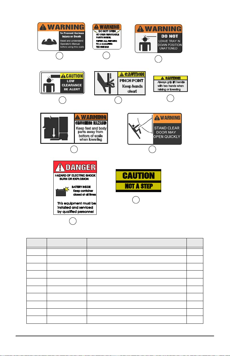
Figure 1-3. Safety Decals
Item # Part # Description Qty
1 151908
2 151906
3 151907
4 151904
5 151909
6 151910
7 151898
8 151902
9
10 151901
Read Manual
Warning, Do Not Open
Warning, Do Not Leave Tray Down
Caution, Low Clearance
Caution, Pinch Point
Caution, Always Grip With Two Hands
Warning, Crushing Hazard
Warning, Opens Quickly
Warning, Battery
Caution, Not A Step
1
1
2
1
6
4
4
2
1
1
Introduction 5
Page 10
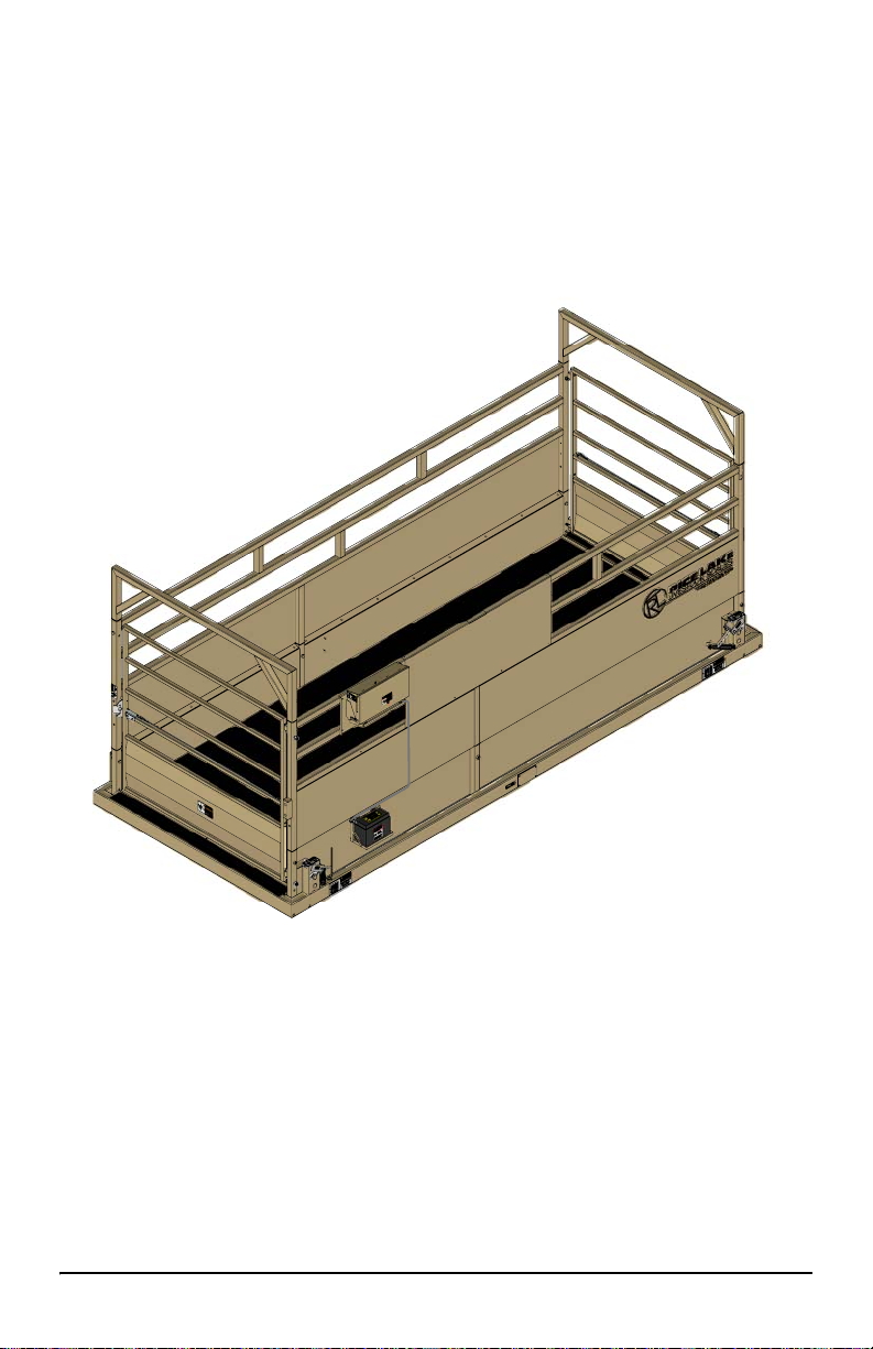
1. 2 Ov e rv ie w
The MAS-P shown below consists of a sheeted animal cage suspended by four S-type
load cells through a cam style On-Board
transport mode, the scale system is locked down, protecting the load cells from damage during transport. The scale is rais
tem. A digital indicator is connected to th
The MA
a low deck height
S-P can be used on any firm surface up to 7% grade (4-degree slope) and has
(6”) for easy step in.
lift system on top a portable base frame. In
ed to the weigh mode using a lever and cam sys-
e scale to display the weight.
Figure 1-4. MAS-P Animal Scale
6 MAS-P Animal Scale Operator’s Manual
Page 11
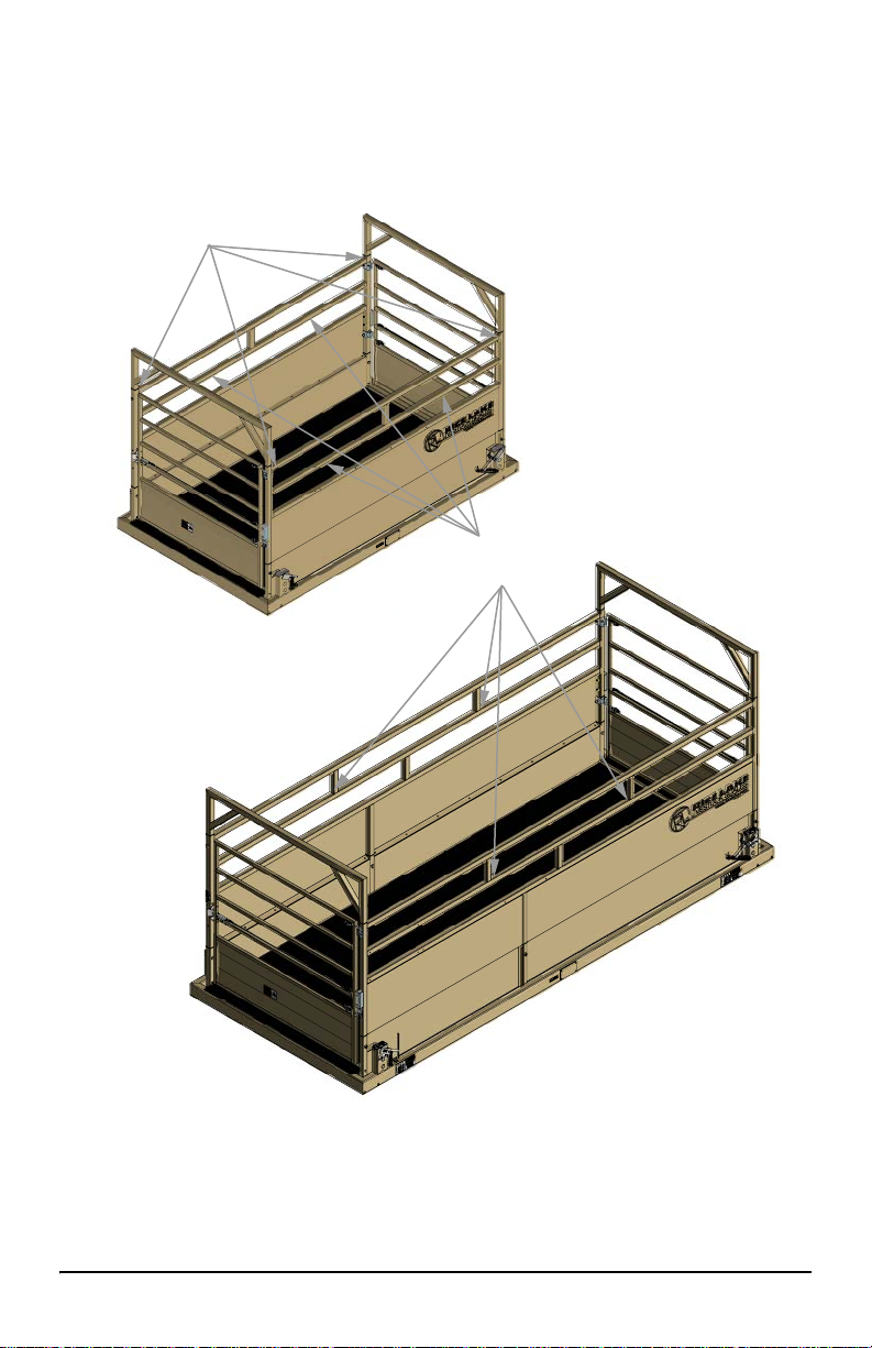
1.3 Lifting Instructions
Lift from here with
forklift or straps
Alternate Strap Location
Lift the scale only in designated locations (see Figure 1-5). The scale may be lifted by
forklift (ensuring the forks reach through both
loader. Ensure the scale is in the transport mode (locked down – see next section)
when loading and transporting the scale.
walls), or by 4 straps and a crane or
Figure 1-5. Lift Points
Introduction 7
Page 12

2.0 Assembly
Note
Lifting
Fixture
Nylon Locknut
9 FEET
11 FEET
2.1 Unloading
2.1.1 Install one lifting fixture on each of the four corners.
If lifting fixtures are in place, skip to Section 2.1.2.
1. Remove the nylon locknut from the bolt installed for shipping.
2. Place the lifting fixture with small hole over the bolt.
3. Reinstall the nut leaving the fixture free to move.
Figure 2-1. Lifting Fixture
2.1.2 Slinging the scale.
MAS-P can be slung with 4 equal length straps connected from the lifting lugs to a
single point in the center.
• Strap length 8 x 13 = 7 ft minimum
• Strap length 8 x 18 = 10 ft minimum
1 MAS-P Animal Scale Operator’s Manual
Figure 2-2. Slinging the Scale
Page 13

2.1.3 Lift the scale.
Shipping Stub
Note
1. If stacked, monitor the four corners directly below the lifting fixtures.
2. Each corner has a shipping stub inserted,
ensure they remain with the lower scale.
3. Once the upper scale of the stack is rem
Figure 2-3. Shipping Stub
these stubs are not bolted in place,
oved the stubs can be discarded.
4. The scale can now be stored as is or placed on a
relatively flat location to be
assembled.
2.2 Package Removal
The indicator is shrink wrapped for transportation. Be careful when removing to
avoid damaging the indicator when removed.
1. Remove indicator, then re-strap the walls if
packaged.
The bolt that holds the walls and the cross members in place during
shipping is not used for assembly.
Please recycle the packaging material.
Place the parts safely and in a location they will not be damaged.
the scale is to be transported while
Assembly 2
Page 14

2.3 Cage Assembly
Silicone
Wall Insert
WARNING
Note
Note
2.3.1 Apply the silicone bead (Mobile scales only)
Before installing the walls a silicone bead must be added.
1. Clean the upper flange of the floor and the low
spirits.
2. Apply an 1/8” bead of silicone along the upper edge of the floor panel along the
enti
re length as shown in Figure 2-4.
er wall flange with mineral
Figure 2-4. Silicon Bead
2.3.2 Install walls
Wall installation should be done with 2 people or an overhead
crane.
1. Lift the first wall by using one sling in the center.
The wall with the operator’s instructions is mounted on the left side.
2. Stand the wall vertical and place the inserts from the wall into the tubes of the
cage floor. The more vertical the wall the easier assembly will be.
3. Repeat for the opposite wall.
4. Install the top cross members.
5. Insert the 3/4 x 3 1/2” bolts through the cage wall and insert s on the indicator
the cage, head of bolt to the inside.
side of
A come-along from the top of the cross member to bottom of the cage
corner post may be required.
For 18 ft scales a 1/2 x 3” bolt and nyl
post with the nut on the outside.
3 MAS-P Animal Scale Operator’s Manual
on locknut is installed on the center
Page 15

2.3.3 Install the Gate
Hook Bolt
Spring Pin
Nut and washer
Cage Wall
Gate
Jam nut and washer
Nylon washer
Install Spring Pins
after gate is in
place.
Note
Install the gate with the hinge bolts on the opposite side of the scale.
Hook bolts must be assembled with lock washer on the inside of gate
and the jam nut on the outside.
Figure 2-5. Lower Hook Bolt
1. Install jam nut and lock washer onto the hook bolts. Screw the nut on about 2”.
2. Insert one hook bolt into the lower and upper holes of the cage wall with the
hoo
k portion pointing upward.
3. Install nut and washer onto the hook bolts s
4. Place nylon washer onto the hook portion of the upper and lower hook bolts
install the gate onto the hooks.
ecuring them to the cage wall.
5. Insert roll pin through the hook bolts.
6. Repeat steps 2-4 for second gate.
7. Adjust the hinge side gap between the gate and the cage wall to about 3” and
nge bolts.
snug hi
Assembly 4
and
Page 16

2.3.4 Complete Cage Assembly
Note
1. Install the 5/16” carriage bolts and serrated nuts with the head of the bolts on the
inside of the cage. Begin by tightening the bolts from the center of the sheet
section working outward.
2. Tighten the 3/4” x 3 1/2” bolts installed in Section 2.3.2.
3. Assemble the latch with 3/8 x 3 1/4” bolts, lock washers, nuts and the latch pin
wit
h the supplied hardware.
Figure 2-6. Latch Assembly
4. Install the 3/4” EVA hose on the latch pin (Mobile units only).
5. Adjust the gates and latches per the adjustment procedure.
2.4 Gate and Latch Adjustment Procedure
The gates shall be assembled following the listed criteria:
• Hook Bolts - Assemble with lock washer on inside of gate and
jam nut on the outside.
• Hinge Side Gap - Approximately 3” between the gate and the
corner post.
• Gate Latch Pin - Install rubber tubing on the latch pin (Mobile
units only).
Adjust gates as follows:
1. Adjust the hook bolts to align the top of the gate on the latch side with the top of
the cage wall.
2. Adjust the hook bolts so the latch side gap is about 1 1/2”.
3. Install and adjust the latch so the gate latch pin does not rub on the top or bottom
of the latch.
5 MAS-P Animal Scale Operator’s Manual
Adjust the hook bolts only if necessary.
Page 17

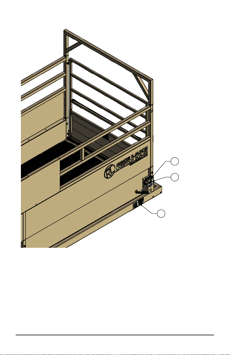
2.5 Mount the 920i Weighcenter – Optional
Adhesive
Conduit Clamp
9/32Ø
1. Before installing the bracket a bead of silicone must be added. See Figure 2-7.
(Apply silicone where labeled adhesive)
2. Clean the wall tubes where bracket will mount and the s
on the mount bracket with mineral spirits.
3. Install the adhesive tape on the mounting bracket between the holes.
4. Place the mounting brac
to the cage.
5. Secure with four bolts.
ket onto the cage wall by pressing the adhesive tightly
pace between the holes
Figure 2-7. Control Box Mounting
Assembly 6
Page 18

2.5.1 Battery Mount – Optional
Note
8 x 13 Scale
8 x 18 Scale
The mounting of the optional battery box differs slightly depending on
the scale size.
Figure 2-8. Battery Mount
1. Mount the upper mounting bracket with the 5/16 x 3/4” bol ts supplied, uti lizing
the exi
sting wall panel bolt holes. See Figure 2-9.
2. Hang the battery bracket from the upper mount and in stall the 5/16 x 3/4 ” bolts
that are supplied.
3. Drill a 3/8” hole through the wall panel aligned with the lower mounting tab.
4. Sandwich the battery strap between the
5. Install the 5/16 x 1/2” carriage bolt.
6. Route the indicator conduit from the control box to the battery as shown in
Figure 2-9.
7. Install the lower 90° conduit connector into the mounting tab.
8. Route the scale cable to the connector located
9. Route the power wire to the battery, see Figure 2-9.
lower mount and the cage wall.
to the left.
Figure 2-9. Mounting Holes
7 MAS-P Animal Scale Operator’s Manual
Page 19

Battery Box Connections
1. Connect the scale cable and secure with a cable tie.
2. Connect the power wires as shown in Figure 2-10.
3. Replace the battery cover.
Figure 2-10. Battery Connections
Assembly 8
Page 20

3.0 Installation
Scale Cable
Bubble Level
As with any weighing equipment, the accuracy of the scale is dependent on the
installation. The following points must be adhered to when installing the MAS-P
Animal Scale.
3.1 All Installations
In all installations, the scale must be level to ensure proper operation. All MAS-P
Animal Scales are equipped with a bubble level (located on top the base frame – see
Figure 3-1). Ensure the bubble is fully inside the circle marked on the top of the level.
3.2 Permanent Installation
Rice Lake Weighing Systems recommend a concrete foundation (piles or piers) for
permanent installations. The foundation must be able to support the gross weight o f
the scale (scale dead weight plus scale capacity), and the piles or piers must be
situated directly under the load cell stands (see shimming location in Figure 3-1). The
foundation must not be subject to distortion or motion due to frost action. A qualified
local
professional should be consulted to recommend the proper size of foundation for
the location. Foundation dimensional requirements are available from the dealer or
Rice Lake Weighing Systems. Requirements may vary from one Weights and
Measures jurisdiction to another, please contact the local office.
3.3 Portable Installation
The MAS-P is ideal for use in many locations. Simply load and unload the scale as
described in the Section 1.3 on page 7. Locate the scale in as level a location as
possible, and shim (with wood or me tal s hims) under the load
scale is level as described above. Please contact the local Weights and Measures
office regarding the moving of the scale to ensure the validity of the certification.
cell stands to ensure the
Figure 3-1. Shim/Load Cell Stand Locations
3.4 Switching Between Modes
3.4.1 Converting to Weigh Mode
1. Place the scale in as level a location as possible. Ensure there are no obstructions
under the deck that would affect weighing accuracy. Check the bubble level. Use
shims or timbers to ensure the scale is as close to level as possible.
9 MAS-P Animal Scale Operator’s Manual
Page 21

Note
The scale will weigh properly on a slope up to 4 degrees,
Note
WARNING
Note
WARNING
Rotate Cam To
Raise Scale Into
Weigh Position
(See Decal)
approximately 7%).
2. Inspect all four corners of the scale. Although the scale will weigh properly up
to four degrees off level, individual corners of the scale should not be allowed to
teeter. If any of the corners are not contacting the ground, place shims directly
under the base frame, under the load cell stands, to prevent teetering. (See
Figure 3-1)
3. Plug the indicator into the scale cable. The scale
cable runs from the junction
box (inside the base frame) to the indicator. (See Figure 3-1)
4. Connect power to the indicator and switch ON.
NG BOTH HANDS, raise the platform to enable the scale (See Figure 3-2)
5. USI
The lift mechanism is an over center cam style lift and lock. If not
disturbed, the scale will remain “locked” in the up position.
Always grip lift handle with two hands when raising and lowering
the scale.
Cam levers point toward each other in weigh mode and away from each
other in transport. See decals for direction of levers in each mode.
6. You are now ready to weigh.
3.4.2 Converting to Transport Mode
When the scale is not in use the scale should be locked down in transport mode to
prevent any accidental overload of the weigh system.
1. USIN
2. Turn off indicator. A stand alone indicator should be stored indoors when the
G BOTH HANDS disengage and lock the scale in transport mode by
rotating all four cam levers counter clockwise into the fully locked position.
The lift mechanism is an over center cam style lift and lock. If not
disturbed, the scale will remain “locked” in the up position.
Always grip lift handle with two hands when raising and lowering
the scale.
Cam levers point toward each other in weigh mode and away from each
other in transport. See decals for direction of levers in each mode.
scale is not in use. The weigh center should be closed and latch to prevent
damage.
Figure 3-2. Scale Lift
Installation 10
Page 22

4.0 Repair Parts
**Lift Mechanism
*
Figure 4-1. MAS-M
*See Figure 4-2 Details A-D for gate hardware (item 14).
**See Figure 4-2 Detail E for lift mechanism parts.
11 MAS-P Animal Scale Operator’s Manual
Page 23

Item No. Part No. Description
1
130931 Cage Crossmember
2
106387 Bumper
131708 Cage Wall 13’
3
131946 Cage Wall 18’ Right
131708 Cage Wall 13’
4
131947 Cage Wall 18’ Left
6
131782 Gate Short Sheeted
7
126787 Scale T-belting (83” width)
8
127081 Bubble Level Circular
9
127561 Scale Cable Female MS Conn 132”
10
11
12
14
15
16
17
18
19
20
21
22
127740 Cover Plate Scale Frame/J-box
126819 Foam Gasket J-box
131891 Scale Junction Box 4 Cell SS
131707 Cage Floor MAS8-13
131934 Cage Floor MAS8-18
130842 Rice Lake Decal
15097 Bolt 3/1-10 x 3 1/2
14697 Nut, Lock 3/4-10 Hex, Nylon Insert Zinc
130022 Operator Shield
45728 Screw, Self Drilling 12-24 x 7/8
132692 Label MASM Weigh/Transport Mode
127094 Label MASM Transport/Weigh Mode
131436 920i Weighcenter (See Operator’s Manual PN 159192)
Battery
Repair Parts 12
Page 24

34
'HWDLO'
'RRU+DUGZDUH/DWFK
45
19
22
42
36
20
'HWDLO%
'RRU+DUGZDUH+LQJH
13 15
33
24
14
'HWDLO$
'RRU+DUGZDUH/DWFK6LGH
18
20
56
19
'HWDLO(
/LIWLQJ0HFKDQLVP
9
17
2
3
6
57
58
59
60
61
16
16
58
65
62
63
64
'HWDLO&
'RRU+DUGZDUH+LQJH6LGH
43
44
35
42
13 MAS-P Animal Scale Operator’s Manual
Figure 4-2. MAS-M Details
Page 25

Item No. Part No. Description
127184 Upper Notched Load Cell Pin
2
21444 Load Cell S-Type 10K
3
127163 Eyebolt Machined 10K
127668 Lower Load Cell Retainer
6
127200 Load Cell Cam Stand Cover SS
9
127007 Bolt 1/4x1/2
151807 Washer, Plain 3/4in Nylon
13
110950 Pin, Spring 1/4 x 1 1/4
14
151589 Hinge Hanger Bolt Hook
15
127684 Plug Plastic Round 2”
16
127177 Lower Notched Load Cell Pin
17
126926 Pin Spring Slotted 1/4x2-1/4
127033 Cap Screw, 3/8-16 x 3/4
18
15159 Washer, 3/8 Lock
19
132684 Nut, 3/8-16 Grade5
20
131784 Gate Latch
22
127021 Hair Pin 1/8 x 2 9/16
15181 Washer, 3/4
24
132179 Hinge Bracket
31
111074 Nut, 3/4-10NC
33
132217 Jam Nut, 3/4-10NC
34
21939 Washer, 5/16
35
131886 Cable, 1/4” OD x 6 ft
36
71872 Bolt, 3/4-10NC x 4
37
14697 Nut, Lock 3/4-10NC
39
131887 Quick Link 1/4 in
42
131701 Eye Bolt, 5/16-18 x 2 1/2
43
14646 Nut, Lock 5/16-18NC
44
39528 Bolt, 3/8-16NC x 2 1/4
45
132427 Strike Plate
56
131787 Cam with Lockdown
57
127165 Spacer Upper Notched Pin
58
127732 Cam Handle
59
131785 Cam Without Lockdown
60
15167 Lockwasher ½
61
14765 Bolt 1/2 x 4
127561 Scale Cable Female MS Conn 132”
22093 Bolt 3/8 x 2 Grade5
62
15161 Flat washer 3/8 SS SAE
63
126992 Nut 3/8 SS
64
Repair Parts 14
Page 26

5.0 Maintenance
Note
5.1 Maintenance Schedule
Weekly
1. Check entire scale for buildup of debris. Remove any debris found
on, under or around the scale.
2. Check for dirt and debris in the load c
3. Check all external cables and conduit for damage.
Yearly (in addition to weekly and monthly maintenance)
1. Disassemble each load cell location and grease all pins and eyebolts.
5.2 Scale Maintenance Procedures
Cleaning Load Cell Stands
It is very important to keep any excess debris from building up in the load cell
stand. Lift scale and block it up, clean any dirt out of the load cell stands
through the drain holes located at the bottom of the stand.
Disassembly and Greasing
This is very important to ensure the long life of your unit. Use the parts list
drawings for item numbers.
Use quality high-pressure grease.
Avoid bending or twisting the load cell wires.
ell stands and clean accordingly.
a. Remove the cell stand cover (27).
b. Remove the plug covers (34)
c. Remove the bolt which holds together items 26, 39, 38.
d. While holding the cam handle (36),
e. Remove the load cell pin (37)
assembly will be free on top and rest against the inside of the cell
stand.
f. Remove the inner cam (26).
g. Remove the lower retainer (33)
h. Grease all bearing surfaces except where
(upper and lower pins, cams, upper and lower eyebolts).
Reassemble in reverse order as
15 MAS-P Animal Scale Operator’s Manual
described above.
remove the outer cam (38).
and spacers (35). The load cell
the eyebolt contacts the pin
Page 27

26
27
28
35
36
33
37
38
39
40
34
Figure 5-1. Disassembly and Greasing
Maintenance 16
Page 28

Load Cell #1
Load Cell #2
Load Cell #4
Load Cell #3
Scale Cable
Junction Box
Trimmers
Load Cell #4
Load Cell #1
Load Cell #2
Load Cell #3
Indicator
Black
Green
White
Shield
Red
+E
-E
+S
-S
GND
V1 V2 V3 V4
Load cell wiring shown is effective for all models later
then 09/17/2013, models built prior that date should
rewire the scale to the updated configuration. For
information on rewire, download Technical Bulletin
(PN 159193) from www.ricelake.com
Note
DA
B
Indicator
AD
CB
Scale
A -EXC Black
B +SIG Green
C +EXC Red
D -SIG White
Connector
C
Figure 5-2. Load Cell Wiring Diagram
17 MAS-P Animal Scale Operator’s Manual
Figure 5-3. Scale/Indicator System Connection
Page 29

5.3 Specifications
t
N
A
T
I
O
N
A
L
C
O
N
F
E
R
E
N
C
E
t
O
N
W
E
I
G
H
T
S
A
N
D
M
E
A
S
U
R
E
S
MAS8-13 MAS8-18
Length Overall
Length Deck
Width Overall
Width Deck
Deck Height
Height
Deck Covering
Weight
Capacity
Section Cap
Approval Class
Approvals
13’-6” 19’-3”
12’-9” 18’-6”
8’-4” 8’-4”
7’-5” 7’-5”
6” 6”
99” 99”
5/8” Recycled One Piece Molded Rubber
Flooring System
2600 lbs. 3500 lbs.
15000 lbs. 20000 lbs.
10000 lbs. 20000 lbs.
IIIL (IIIHD) IIIL (IIIHD)
99-091A4
AM4*
Grad Size
**Paint
5 lb (2 kg) 5 lb (2 kg)
Powder Coated Galvanized Steel
**Structural Steel is not galvanized.
Notes:
Size / Model # ___________________________
Serial # _________________________________
Date Purchased _________________________
Unit ID # _______________________________
Maintenance 18
Page 30

MAS-P Limited Warranty
Rice Lake Weighing Systems (RLWS) warrants that all RLWS equipment and
systems properly installed by a Distributor or Original Equipment Manufacturer
(OEM) will operate per written specifications as confirmed by t he Distributor/OEM
and accepted by RLWS. All systems and components are warranted against defects in
materials and workmanship for two years.
RL WS warrants that the equipment sold hereunder will conform to the current written
specifications authorized by RLWS. RLWS warrants the equipment against faulty
workmanship and defective materials. If any equipment fails to conform to these
warranties, RLWS will, at its option, repair or replace such goods returned within the
warranty period subject to the following conditions:
• Upon discovery by Buyer of such nonconformity, RLWS will be given
prompt written notice with a detailed explanation of the alleged deficiencies.
• Individual electronic components returned to RLWS for warranty purposes
must be packaged to prevent electrostatic discharge (ESD) damage in
shipment. Packaging requirements are listed in a publication, Protecting
Your Components From Static Damage in Shipment, available from RLWS
Equipment Return Department.
• Examination of such equipment by RLWS confirms that the nonconformity
actually exists, and was not caused by accident, misuse, neglect, alteration,
improper installation, improper repair or improper testing; RLWS shall be
the sole judge of all alleged non-conformities.
• Such equipment has not been modified, altered, or changed by any person
other than RLWS or its duly authorized repair agents.
• RLWS will have a reasonable time to repair or replace the defective
equipment. Buyer is responsible for shipping charges both ways.
• In no event will RLWS be responsible for travel time or on-location repairs,
including assembly or disassembly of equipment, nor will RLWS be liable
for the cost of any repairs made by others.
THESE WARRANTIES EXCLUDE ALL OTHER WARRANTIES, EXPRESSED OR IMPLIED,
INCLUDING WITHOUT LIMITATION WARRANTIES OF MERCHANTABILITY OR
FITNESS FOR A PARTICULAR PURPOSE. NEITHER RLWS NOR DISTRIBUTOR WILL,
IN ANY EVENT, BE LIABLE FOR INCIDENTAL OR CONSEQUENTIAL DAMAGES.
RLWS AND BUYER AGREE THAT RLWS’ SOLE AND EXCLUSIVE LIABILITY
HEREUNDER IS LIMITED TO REPA I R OR REPLACEMENT OF SUCH GOODS. IN
ACCEPTING THIS WARRANTY, THE BUYER WAIVES ANY AND ALL OTHER CLAIMS
TO WARRANTY.
SHOULD THE SELLER BE OTHER THAN RLWS, THE BUYER AGREES TO LOOK ONLY
TO THE SELLER FOR WARRANTY CLAIMS.
NO TERMS, CONDIT IONS, UNDERSTANDING, OR AGREEMENTS PURPORTING TO
MODIFY THE TERMS OF THIS WARRANTY SHALL HAVE ANY LEGAL EFFECT UNLESS
MADE IN WRITING AND SIGNED BY A CORPORATE OFFICER OF RLWS AND THE
BUYER.
© Rice Lake Weighing Systems, Inc. Rice Lake, WI USA. All Rights Reserved.
RICE LAKE WEIGHING SYSTEMS • 230 WEST COLEMAN STREET • RICE LAKE,
19 MAS-P Animal Scale Operator’s Manual
WISCONSIN 54868 • USA
Page 31

For More Information
Web Site
• Frequently Asked Questions (FAQs) at
http://www.ricelake.com/faqs.aspx
Contact Information
Hours of Operation
Knowledgeable customer service representatives are available 6:30 a.m. 6:30 p.m. Monday through Friday and 8 a.m. to 12 noon on Saturday. (CST)
Telephone
• Sales/Technical Support 800-472-6703
• Canadian and Mexican Customers 800-321-6703
• International 715-234-9171
Immediate/Emergency Service
For immediate assistance call toll-free 1-800-472-6703 (Canadian and
Mexican customers please call 1-800-321-6703). If you are calling after
standard business hours and have an urgent scale outage or emergency, press
1 to reach on-call personnel.
Fax
Fax Number 715-234-6967
Email
• US sales and product information at
prodinfo@ricelake.com
• International (non-US) sales and product information at
intlsales@ricelake.com
Mailing Address
Rice Lake Weighing Systems
230 West Coleman Street
Rice Lake, WI 54868 USA
Maintenance 20
Page 32

Notes
21 MAS-P Animal Scale Operator’s Manual
Page 33

Notes
Maintenance 22
Page 34

Notes
23 MAS-P Animal Scale Operator’s Manual
Page 35

Page 36

230 W. Coleman St. t Rice Lake, WI 54868 t USA
U.S. 800-472-6703 t Canada/Mexico 800-321-6703 t International 715-234-9171 t Europe +31 (0) 88 2349171
© Rice Lake Weighing Systems 11/2013 PN 132795 Rev D
 Loading...