

Page 1

Multiple Animal Scale Mobile
Installation/Service
Manual
132051 Rev E
Page 2

Page 3

Contents
Technical training seminars are available through Rice Lake Weighing Systems.
Course descriptions and dates can be viewed at www.ricelake.com/training
or obtained by calling 715-234-9171 and asking for the training department.
1.0 Introduction......................................................................... 1
1.1 Safety . . . . . . . . . . . . . . . . . . . . . . . . . . . . . . . . . . . . . . . . . 1
1.2 Overview . . . . . . . . . . . . . . . . . . . . . . . . . . . . . . . . . . . . . . . 6
1.3 Lifting Instructions . . . . . . . . . . . . . . . . . . . . . . . . . . . . . . . . 7
2.0 Assembly............................................................................. 8
2.1 Unloading. . . . . . . . . . . . . . . . . . . . . . . . . . . . . . . . . . . . . . . 8
2.1.1 Install one lifting fixture on each of the four corners. . . . . . . 8
2.1.2 Slinging the scale. . . . . . . . . . . . . . . . . . . . . . . . . . . . . . . . 8
2.1.3 Lift the scale. . . . . . . . . . . . . . . . . . . . . . . . . . . . . . . . . . . . 9
2.2 Package Removal . . . . . . . . . . . . . . . . . . . . . . . . . . . . . . . . 9
2.2.1 Wheel Assembly and Torque Specification. . . . . . . . . . . . 10
2.3 Cage Assembly . . . . . . . . . . . . . . . . . . . . . . . . . . . . . . . . . 11
2.3.1 Apply the silicone bead . . . . . . . . . . . . . . . . . . . . . . . . . . 11
2.3.2 Install walls. . . . . . . . . . . . . . . . . . . . . . . . . . . . . . . . . . . . 11
2.3.3 Install the Gate. . . . . . . . . . . . . . . . . . . . . . . . . . . . . . . . . 12
2.3.4 Complete Cage Assembly . . . . . . . . . . . . . . . . . . . . . . . . 13
2.4 Gate and Latch Adjustment Procedure . . . . . . . . . . . . . . . 14
2.4.1 Hitch Assembly . . . . . . . . . . . . . . . . . . . . . . . . . . . . . . . . 15
2.5 Optional 920i Weighcenter Mounting . . . . . . . . . . . . . . . . . 16
2.6 T-Belt . . . . . . . . . . . . . . . . . . . . . . . . . . . . . . . . . . . . . . . . . 17
3.0 Towing Instructions .......................................................... 18
3.1 Switching Between Modes . . . . . . . . . . . . . . . . . . . . . . . . 20
3.1.1 Converting to Weigh Mode . . . . . . . . . . . . . . . . . . . . . . . 20
3.1.2 Converting to Transport Mode . . . . . . . . . . . . . . . . . . . . 22
4.0 Repair Parts ...................................................................... 24
5.0 Maintenance ..................................................................... 30
5.1 Maintenance Schedule . . . . . . . . . . . . . . . . . . . . . . . . . . . 30
5.2 Scale Maintenance Procedures . . . . . . . . . . . . . . . . . . . . . 31
5.2.1 Cleaning Load Cell Stands . . . . . . . . . . . . . . . . . . . . . . . 31
5.2.2 Disassembly and Greasing . . . . . . . . . . . . . . . . . . . . . . . 31
5.3 Scale Maintenance Procedures . . . . . . . . . . . . . . . . . . . . . 32
5.3.1 How to Use The Electric Brakes Properly. . . . . . . . . . . . . 32
5.3.2 Synchronizing The Scale Brakes . . . . . . . . . . . . . . . . . . . 32
5.3.3 Brake Adjustment . . . . . . . . . . . . . . . . . . . . . . . . . . . . . . 32
5.3.4 Wheel Assembly and Torque Specification. . . . . . . . . . . . 33
5.3.5 Bearing Adjustment . . . . . . . . . . . . . . . . . . . . . . . . . . . . . 33
© Rice Lake Weighing Systems. All rights reserved. Printed in the United States of America.
Specifications subject to change without notice.
Rice Lake Weighing Systems is an ISO 9001 registered company.
February 28, 2014
Contents i
Page 4

5.3.6 Axle Parts . . . . . . . . . . . . . . . . . . . . . . . . . . . . . . . . . . . . 34
Rice Lake continually offers web-based video training on a growing selection
of product-related topics at no cost. Visit www.ricelake.com/webinars.
5.4 Gathering Panel Attachment . . . . . . . . . . . . . . . . . . . . . . . 34
5.5 Wiring Diagrams . . . . . . . . . . . . . . . . . . . . . . . . . . . . . . . . . 36
5.6 Specifications. . . . . . . . . . . . . . . . . . . . . . . . . . . . . . . . . . . 38
5.7 Towing Checklist . . . . . . . . . . . . . . . . . . . . . . . . . . . . . . . . 39
Mobile Group Limited Warranty.................................................... 40
For More Information .................................................................... 41
ii MAS-M Operator’s Manual
Page 5

1.0 Introduction
DANGER
WARNING
CAUTION
Important
Congratulations on your purchase of a Multiple Animal Scale Mobile (MAS-M) using
On-Board technology. This system is manufactured with top quality components and
is engineered using the latest technology to provide operating features and reliability
unmatched for years to come.
Please take the time to read this manual completely through before attempting to use
the system. Although the MAS-M has been designed for easy set up and use, a
thorough understanding of this manual will ensure that you receive the maximum
benefit from the system.
If you have any questions or comments please contact Rice Lake Weighing Systems.
1. 1 Sa f et y
Safety Symbol Definitions:
Indicates an imminently hazardous situation that, if not avoided,
will result in death or serious injury.
Indicates a potentially hazardous situation that, if not avoided
could result in death or serious injury, and includes hazards that
are exposed when guards are removed.
Indicates a potentially hazardous situation that, if not avoided may
result in minor or moderate injury.
Indicates information about procedures that, if not observed,
could result in damage to equipment or corruption to and loss of
data.
General Safety
Do not operate or work on this equipment unless you have read
and understand the instructions and warnings in this Manual.
Failure to follow the instructions or heed the warnings could
result in injury or death. Contact any Rice Lake Weighing
System dealer for replacement manuals. Proper care is your
responsibility.
Introduction 1
Page 6

Failure to heed may result in serious injury of death.
WARNING
Important
DO NOT allow minors (children) or inexperienced persons to operate this unit.
DO NOT operate without all shields and guards in place.
DO NOT jump up and down on the scale.
DO NOT use for purposes other than weighing.
DO NOT place fingers into slots or possible pinch points.
DO NOT place hands, feet or any body part underneath the scale at any time. The
scale could be lowered at any time, crushing body parts.
DO NOT use any load bearing component that is worn beyond 5% of the original
dimension.
DO NOT use this product if any of the components are cracked.
DO NOT exceed the rated load limit of the unit.
DO NOT make alterations or modifications to the unit.
DO NOT remove or obscure warning labels.
Keep hands, feet and loose clothing away from moving parts.
Some procedures described in this manual require work inside the indicator enclo-
sure. These procedures are to be performed by qualified service
personnel only.
Always be certain when lowering the scale that everyone is clear of the scale and
any moving parts.
Use two hands when gripping the lift handle to raise or lower the scale.
Be sure the gates are latched or tied inward before transporting the scale.
Ensure all three hitch lock pins are installed and the suspension stops are in the
transport position before moving the scale.
This unit is not intended for the transportation of livestock or any other goods. Any
addition of weight to the scale in transport mode may cause premature
component failure and voids the Rice Lake warranty.
Animal Safety:
Animal safety is a very serious issue and must be observed when handling any
type of animal.
The scale surface may become slippery during use; a build-up of manure on the
scale may reduce traction. It is recommended that you take any necessary
precautions to maintain an acceptable level of animal footing.
Calibration:
Do not calibrate this scale with a weight cart having a gross weight in excess of
4,000 lbs or 1,815 kg. This device is designed to be calibrated with single block
weights spread evenly throughout the floor of the scale. Shift tests should not be
done with more than 4,000 lbs or 1,815 kg in a 4’ x 4’ area. Failure to comply with
this warning will result in damage to the scale and void the warranty.
2 MAS-M Operator’s Manual
Page 7

%RWK
6LGHV
%RWK
6LGHV
%RWK
6LGHV
%RWK
6LGHV
%RWK
6LGHV
,QVLGH:HLJK
&HQWHU%R[
Items 1-4 are on units equiped
with the 920i Weighcenter only.
Note
Figure 1-1. Safety Decal Locations
Introduction 3
Page 8

Figure 1-2. Safety Decal Locations
%RWK
6LGHV
%RWK
6LGHV
%RWK
6LGHV
%RWK
6LGHV
%RWK
6LGHV
4 MAS-M Operator’s Manual
Page 9

Figure 1-3. Safety Decals
Item # Part # Description Qty
1 151908
2 151906
3 151907
4 151904
5 151909
6 151910
7 151898
8 151905
9 151900
10 151902
11 151901
12 128266
13 151987
Read Manual
Warning, Do Not Open
Warning, Do Not Leave Tray Down
Caution, Low Clearance
Caution, Pinch Point
Caution, Always Grip With Two Hands
Warning, Crushing Hazard
Warning, Crushing Hazard, Jack
Warning, Battery
Warning, Opens Quickly
Caution, Not A Step
Do Not Use For Transportation of Goods
Caution, Tripping Hazard
Introduction 5
1
1
2
1
6
4
4
1
1
2
1
2
2
Page 10

1. 2 Ov e rv i ew
The MAS-M is an agricultural implement consisting of a scale with air ride suspension
and swing out hitch, sheeted animal cage suspended by four S-type load cells through
a cam style On-Board scale system, and weigh center. In transport mode the scale
system is locked down, protecting the load cells from damage during transport. To
convert to weigh mode the entire scale is lowered to the ground, the hitch is spl it and
swung outward and the scale is raised to the weigh mode using a lever and cam
system. The weigh center contains the digital indicator and ticket printer. To convert
back to transport mode the process is reversed (lower the scale, swing hitch inward
and lock and raise the suspension using the integral air pump).
The MAS-M can be used on any firm surface up to 7% grade (4-degree slope) and has
a low deck height (6”) for easy step in.
Figure 1-4. Multiple Animal Scale Mobile
6 MAS-M Operator’s Manual
Page 11

1.3 Lifting Instructions
Lift the scale only in designated locations (see Figure 1-5). The scale may be lifted by
forklift (ensuring the forks reach through both walls) or by 4 straps and a crane or
loader. Ensure the scale is in the transport mode (locked down – see next section)
when loading and transporting the scale.
Figure 1-5. Lift Points
Introduction 7
Page 12

2.0 Assembly
Note
Lifting
Fixture
Nylon Locknut
2.1 Unloading
2.1.1 Install one lifting fixture on each of the four corners.
If lifting fixtures are in place, skip to Section 2.1.2
1. Remove the nylon locknut from the bolt inst alled for shipping.
2. Place the lifting fixture with small hole over the bolt.
3. Reinstall the nut leaving the fixture free to move.
Figure 2-1. Lifting Fixture
2.1.2 Slinging the scale.
The MAS-M can be slung using 4 straps conn ected from the lifting lugs to a single
point in the center. To obtain a lifting point closer to the center of gravity straps
should be 1 to 2 ft longer on the rear of the scale. See Figure 2-2.
• Strap length 8 x 13 = 6 ft minimum
• Strap length 8 x 18 = 9 ft minimum
Figure 2-2. Slinging the Scale
8 MAS-M Operator’s Manual
Page 13

2.1.3 Lift the scale.
Shipping Stub
Note
1. If stacked, monitor the four corners directly below the lifting fixtures.
2. Each corner has a shipping stub inserted, these stubs are not bolted in place,
ensure they remain with the lower scale.
3. Once the upper scale of the stack is removed the stubs can be discarded.
Figure 2-3. Shipping Stub
4. The scale can now be stored as is or placed on a relatively flat location to be
assembled.
2.2 Package Removal
The indicator and tires are shrink wrapped for transportation. Be careful when
removing to avoid damaging the indicator or tires when removing.
1. Remove the tires and indicator, then re-strap the walls if the scale is to be
transported while packaged.
The bolt that holds the walls and the cross members in place during
shipping is not used for assembly.
Please recycle the packaging material.
Place the parts safely and in a location they will not be damaged.
Assembly 9
Page 14

2.2.1 Wheel Assembly and Torque Specification
Note
Note
It is extremely important to apply an d maintain proper wheel mounting torque on the
scale axle. Torque is a measure of the amount of tightening applied to a fastener (nut
or bolt) and is expressed as length times force. For example, a force of 90 pounds
applied at the end of a wrench one-foot long will yield 90 ft-lbs of torque. Torque
wrenches are the best method to assure the proper amount of torque is bein g applied.
Wheel bolts/nuts must be tightened and maintained at the proper torque
levels to prevent loose wheels, broken studs and possible dangerous
separation of wheels from the axle. Be sure to use only the fasteners
matched to the cone angle of the wheel (usually 60° or 90°).
The proper procedure for attaching the wheels is as follows:
1. Start all bolts/nuts by hand to prevent cross threading.
2. Tighten bolts/nuts in the sequence shown in Figure 2-4.
The tightening of the fasteners should be done in stages, following the
recommended sequence, tighten fasteners per torque chart in Table 2-1.
3. Wheel bolts/nuts should be re-torqued after the first 10 miles, 25 miles and
again at 50 miles.
Wheel Torque Sequence (ft-lbs)
1st Stage 2nd Stage 3rd Stage
20-25 50-60 90-120
Table 2-1. Wheel Torque
Figure 2-4. Wheel Torque Pattern
4. Once the wheel nuts have been torqued use a white marker to mark the end of
each stud to show they have been torqued.
10 MAS-M Operator’s Manual
Page 15

2.3 Cage Assembly
Silicone
Wall Insert
WARNING
Note
Note
2.3.1 Apply the silicone bead
Before installing the walls a silicone bead must be added.
1. Clean the upper flange of the floor and the lower wall flange with mineral
spirits.
2. Apply an 1/8” bead of silicone along the upper edge of the floor pane l along the
entire length as shown in Figure 2-5.
Figure 2-5. Silicon Bead
2.3.2 Install walls
Wall installation should be done with 2 people or an overhead
crane.
1. Lift the first wall by using one sling in the center.
The wall with the operator’s instructions is mounted on the left side.
2. Stand the wall vertical and place the inserts from the wall into the tubes of the
cage floor. The more vertical the wall the easier assembly will be.
3. Repeat for the opposite wall.
4. Install the top cross members.
5. Insert the 3/4 x 3 1/2” bolts t hrough the cage wall and inserts on the indicator
side of the cage, head of bolt to the inside.
A come-along from the top of the cross member to bottom of the cage
corner post may be required.
For 18 ft scales a 1/2 x 3” bolt and nylon locknut is installed on the center
post with the nut on the outside.
Assembly 11
Page 16
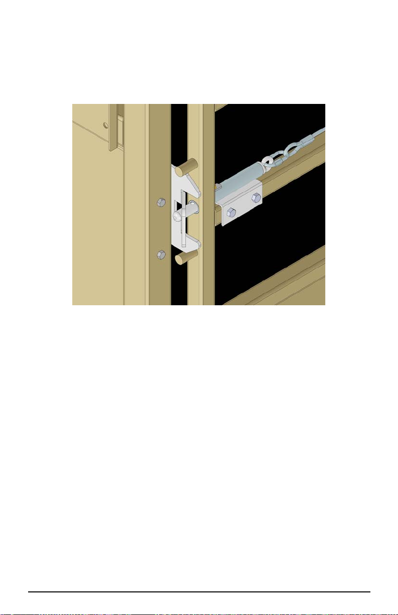
2.3.3 Install the Gate
Note
Hook Bolt
Spring Pin
Nut and washer
Cage Wall
Gate
Jam nut and washer
Nylon washer
Install Spring Pins
after gate is in
place.
Install the gate with the hinge bolts on the opposite side of the scale.
Hook bolts must be assembled with lock washer on the inside of gate
and the jam nut on the outside.
Figure 2-6. Assemble Gate to Scale
1. Install jam nut and lock washer onto the hook bol ts. Screw the nut on abo ut 2”.
2. Insert one hook bolt into the lower and up per holes of the cage wall with the
hook portion pointing upward.
3. Install nut and washer onto the hook bolts securing them to the cage wall.
4. Place nylon washer onto the hook portion of the upper and lower hook bolts and
install the gate onto the hooks.
5. Insert roll pin through the hook bolts.
6. Repeat steps 2-4 for second gate.
7. Adjust the hinge side gap between the gate and the cage wall to about 3” and
snug hinge bolts.
12 MAS-M Operator’s Manual
Page 17
2.3.4 Complete Cage Assembly
1. Install the 5/16” carriage bolts and serrated nuts with the head of the bolts on the
inside of the cage. Begin by tightening the bolts from the center of the sheet
section working outward.
2. Tighten the 3/4” x 3 1/2” bolts installed in Section 2.3.2.
3. Assemble the latch with 3/8 x 3 1/4” bolts, lock washers, nuts and the latch pin
with the supplied hardware.
Figure 2-7. Latch Assembly
4. Install the 3/4” EVA hose on the latch pin (Mobile units only).
5. Adjust the gates and latches per the adjustment procedure.
Assembly 13
Page 18

2.4 Gate and Latch Adjustment Procedure
Note
The gates shall be assembled following the listed criteria:
• Hook Bolts - Assemble with lock washer on inside of gate and jam
nut on the outside.
• Hinge Side Gap - Approximately 3” between the gate and the
corner post.
• Gate Latch Pin - Install rubber tubing on the latch pin (Mobile units
only).
Adjust gates as follows:
1. Adjust the hook bolts to align the top of the gate on the latch side with the top of
the cage wall.
2. Adjust the hook bolts so the latch side gap is about 1 1/2”.
3. Install and adjust the latch so the gate latch pin does not rub on the top or bottom
of the latch. Adjust the hook bolts only if necessary.
14 MAS-M Operator’s Manual
Page 19
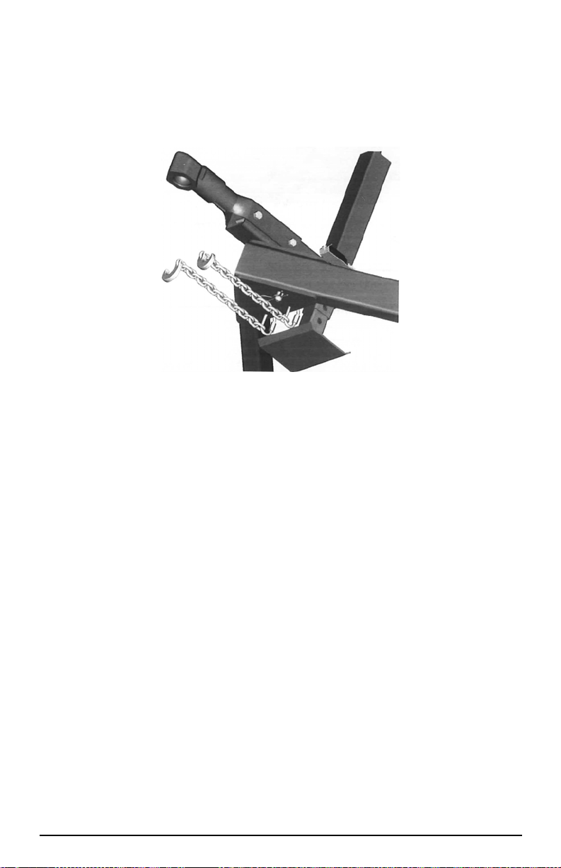
2.4.1 Hitch Assembly
1. If the hitch arm does not come mounted, assemble the right hitch member (wit h
coupler) to the cage using the pin installed in the hole. Ensure the clip pin is
installed on the bottom of the pin.
2. Connect the two halves of the hitch and install the forward pin t hrough bot h left
and right hitch members.
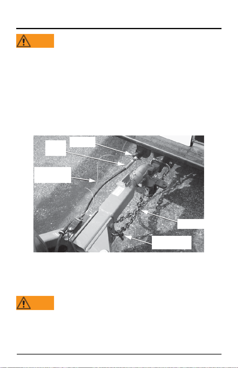
3. Install the safety chains as shown in Figure 2-8.
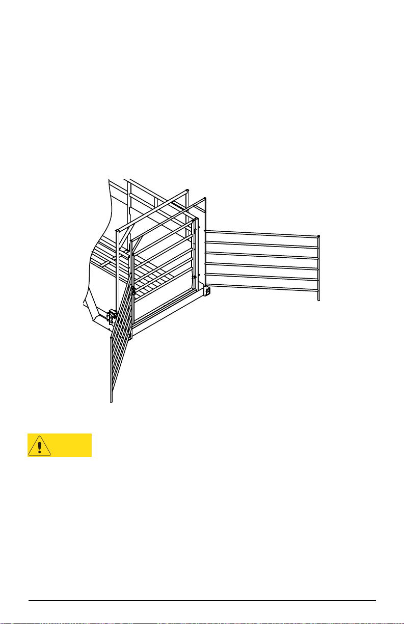
Figure 2-8. Safety Chain
4. Assemble jack, tighten bolts.
5. Install power cable and connect breakaway switch.
6. Connect the slip hook with the safety latch onto one end of each chain.
7. Install the quick link into the 4th link of the chain on the opposite end of the slip
hook.
8. Insert the quick link into the bottom hole on th e hitch mounting plate.
Assembly 15
Page 20
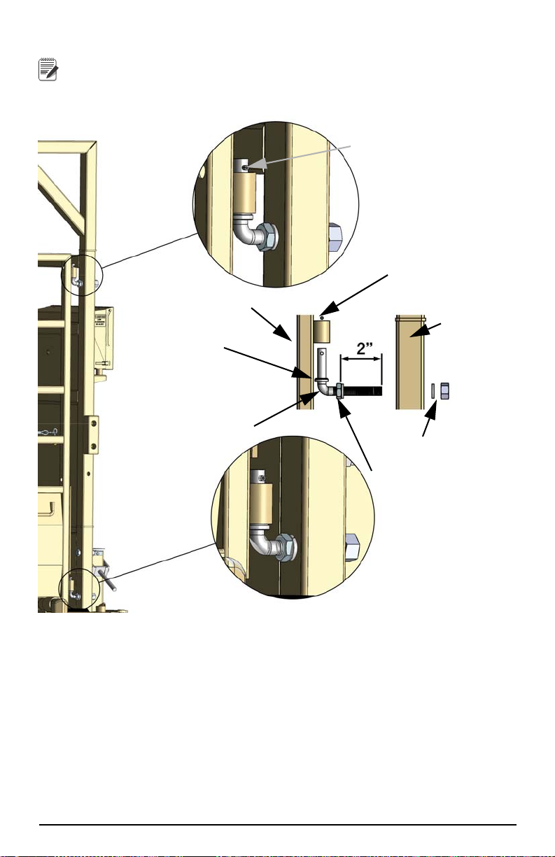
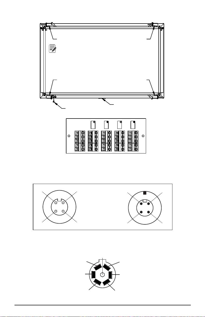
2.5 Optional 920i Weighcenter Mounting
Adhesive
Conduit Clamp 9/32Ø
1. Before installing the bracket a bead of silicone must be added. See Figure 2-9.
(Apply silicone where labeled adhesive)
2. Clean the wall tubes where bracket will mount and the space between the holes
on the mount bracket with mineral spirits.
3. Install the adhesive tape on the mounting bracket between the holes.
4. Place the mounting bracket onto the cage wall by pressing the adhesive tightly
to the cage.
5. Secure with four bolts.
Figure 2-9. Weighcenter Mounting
6. Mount the weighcenter onto the mo unting bracket and route the cable as shown
in Figure 2-9.
7. Install the clamps to secure the conduit.
• Mount the upper conduit clamp using the lower left mounting bracket bolt.
• Secure the lower end of the conduit by drilling a hole through the cage
sheeting and installing the clamp with the bolt provided.
Battery Box Connections
1. Connect the scale cable and secure with a cable tie.
2. Connect the power wires as shown in Figure 2-10.
3. Replace the battery cover.
Figure 2-10. Battery Connections
16 MAS-M Operator’s Manual
Page 21

2.6 T-Belt
Ensure the T-Belt hold down loops are installed and hooked into the corner posts of
the cage.
Figure 2-11. T-Belt
Assembly 17
Page 22
3.0 Towing Instructions
WARNING
Use Adapter
If Required
Cross Chains
Under Hitch
Adjust Safety Chain
Length Here
Hook Up
Electrical
Cable
Attach Breakaway
Switch Cable
To Truck Frame
WARNING
Read these instructions before towing.
This unit is not intended for the transportation of livestock or any
other goods. Any addition of weight to the scale in transport
mode may cause premature component failure and voids the
Rice Lake warranty.
The scale must be in “Transport Mode” to be towed. See Section 3.1.2 on page 22 for
converting to transport mode.
The scale is designed to be towed level (frame parallel to the ground) using a 2” ball.
To achieve the level towing condition, the required hitc h height of the tow ing vehicle
must be approximately 16”. If the hitch of the towing vehicle i s not in this ran ge, use
an adapter to achieve a height in this range. The hitch weight of the scale is
approximately 500lb. An equalizer hitch may be used for towing if desired (such as
the EAZ-LIFT Adjustable Weight Distributing Hitch #1009).
Safety chains must be connected during towing (see Figure 3-1). Connect the safety
chains. Cross the chains under the hitch for proper protection. Safety chain length is
adjustable by inserting the quick link through any link of the chain.
The scale must be connected electrically to the tow vehicle. Ensure that the
wiring of the towing vehicle is compatible with the scale wiring before hooking up.
Figure 3-1. Hitch Connection
See the label on the hitch for the wiring code (or see Figure 5-9 for wiring diagram).
The scale is supplied with a 7-pin connector. It is crucial the wiring is correct so the
battery (which supplies power to the control box) is charged during transport.
Improper wiring can cause brake failure.
If the scale is to be towed at night or if the lights of the tow vehicle are
obstructed by the scale, add on lights are available. These lights plug into a 6-pin
receptacle located on the rear of the battery box and attach magnetically to the
scale frame.
18 MAS-M Operator’s Manual
Page 23
The scale is equipped with electric brakes. The brakes must be synchronized with the
Suspension Stop Right Height Label
Tran s po rt M o d e
Weigh Mode
WARNING
tow vehicle brakes before towing. See Section 5.3.2 on page 32 for procedures. The
breakaway switch for the electric brakes must be connected during towing. This
switch activates the scale brakes in the unlikely event of scale separation from the tow
vehicle. The metal cable must be attached to a point on the tow vehicle other than the
primary connection point.
Figure 3-2. Ride Height
The scale is designed to be towed at a ride height of approximately 8 inches. A ride
height label is attached to every shock absorber to visually confirm the ride height.
After the scale is hooked up to the tow vehicle, check all the ride height labels to
ensure proper air bag inflation. Add or remove air as necessary.
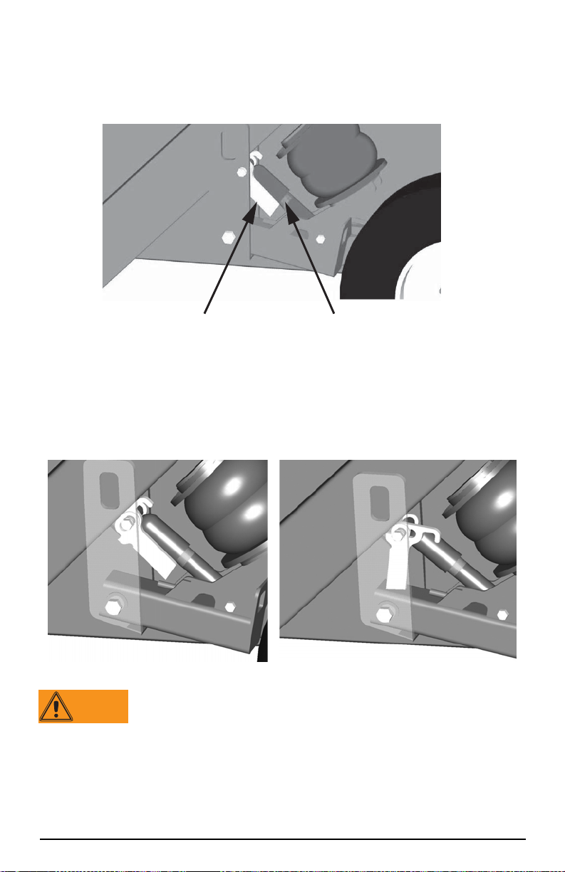
Suspension stops (one on each axle of the scale) are supplied to prevent the scale from
dropping to the ground in the event of an air system failure. These stops must be in
the transport position during towing.
Figure 3-3. Suspension Stop
The Suspension Stops are not to be used as a means of
transporting the scale. It is only to be used to as a safety device,
allowing removal of the scale from the roadway in the event of an
air system failure.
Towing Instructions 19
Page 24

3.1 Switching Between Modes
Note
Note
3.1.1 Converting to Weigh Mode
1. Park the scale in as level a location as possible. Ensure there are no obstructions
under the deck that would affect weighing accuracy.
The scale will weigh properly on a slope up to 4 degrees
(approximately 7%).
2. Turn the power switch located in the weigh center to the ON position.
3. If the scale is not level the indicator will d isplay “
and roll angle below, allowing the scale to be leveled.
4. With the drop leg retracted extend the jack until it begins lifting up on the scale
hitch.
5. Disconnect the scale from the truck hitch and un plug all wiri ng. Move the truck
clear of the scale.
6. Using the hitch jack, lower the scale hitch to the ground.
7. Flip the suspension stops (on each axle of the scale) into the weigh mode (see
Figure 3-3). Scale will not fully lower to ground with stops in transport
position.
8. Ensure the dump valve located on the battery box is cl osed and open all valves
located directly above the air bags.
9. Slowly open the dump valve to empty the air from the scale suspension. The
scale will lower to the ground.
10.Inspect all four corners of the scale. Although the scale will weigh properly up
to four degrees off level, individual corners of the scale should not be allowed to
teeter. If any of the corners are not contacting the ground, either move the scale
to a more level location or do the following:
11.Close the dump valve and turn on the air pump to slightly raise the scal e. Once
the scale frame has lifted sufficiently, turn off the pump.
If the air pump is not functioning, the scale can be raised using the
auxiliary fill directly below the dump valve.
Out Of Level” with the pitch
12.Place shims directly under the base frame, under the load cell stands, to prevent
teetering (see Figure 3-4).
13.Open the dump valves to lower the scale onto the ground and shims.
Figure 3-4. Shimming Locations
20 MAS-M Operator’s Manual
Page 25
14.Unpin the hitch and swing both hitch halves clear.
Note
Rotate Cam To
Raise Scale Into
Weigh Position
(See Decal)
WARNING
Note
The hitch sections can be removed. To remove the hitch, remove the pins
from the scale end of the hitch arms, and pull all wiring through the
driver’s hitch tube.
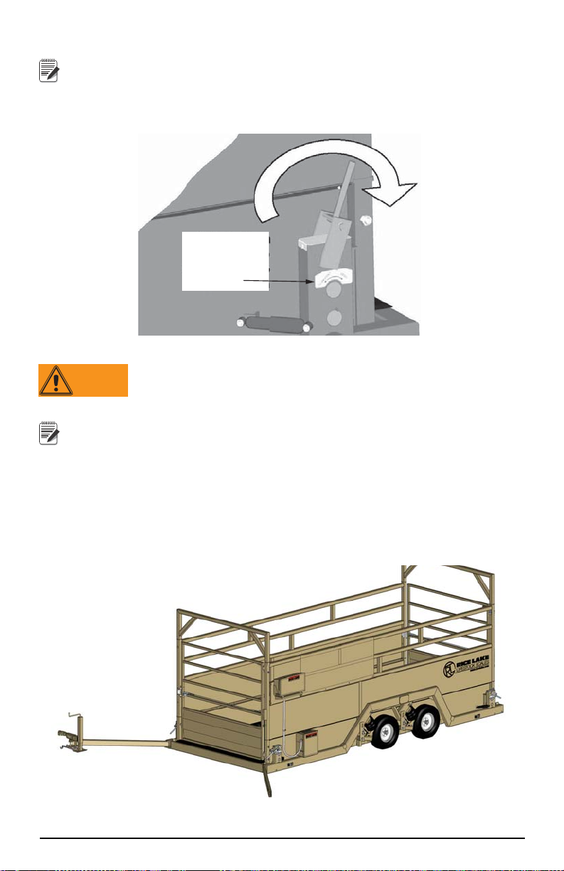
15.USING BOTH HANDS, raise the platform (rotate cam handle in
direction indicated by decal) to enable the scale (see Figure 3-5).
Figure 3-5. Scale Lift
The lift mechanism is an over center cam style lift and lock. If not
disturbed, the scale will remain “locked” in the up (weigh)
position. Always grip lift handle with two hands when raising and
lowering the scale.
Cam levers point toward each other in weigh mode and away from each
other in transport. See decals for direction of levers in each mode.
16.Ensure the weigh center power switch is in the ON position. Verify the indicator
does not show out of level. If it does, shim the scale as necessary (see steps 1113 above).
17.The weigh indicator should be powered u p. The readout of GROSS weight on
the indicator should be near zero (within four percent of the scale capacity). If it
is not, ensure the scale is fully lifted and that there is no debris on or under the
scale.
Figure 3-6. Scale in Weigh Mode
Towing Instructions 21
Page 26

3.1.2 Converting to Transport Mode
WARNING
Note
Proper Ride Height
Over Inflated
Note
WEIGH
T
R
A
N
S
DO NOT ATTEMPT TO MOVE THE
SCALE UNLESS VALVES ARE IN
TRANSPORT POSITION
1. Turn OFF the power switch located in the weigh center. Close and latch the
weight center cover.
2. USING BOTH HANDS lower the platform (rotate the cam handles in the
direction indicated by decal) to disengage the scale. Ensure the handles are in
the fully locked position.
The lift mechanism is an over center cam style lift and lock. If not
disturbed the scale will remain “locked” in the up (weigh)
position. Always grip lift handle with two hands when raising and
lowering the scale.
Cam levers point toward each other in weigh mode and away from each
other in transport. See decals for direction of levers in each mode.
3. Swing the hitch halves together and pin. Ensure the hitch pins have the safety
pins installed.
4. Add air to the scale suspension so that the frame rises evenly off the ground to
the correct ride height of approximately 8 inches (as indicated by the ride height
labels on the shock absorbers). Use either compressor on scale or a remote
compressor connected to the auxiliary air fill.
Figure 3-7. Scale Suspension
5. Close all the air valves. During scale towing, all valves MUST be closed.
After connecting to the tow vehicle you must operate the valves again.
22 MAS-M Operator’s Manual
Figure 3-8. Air Valve Position
Page 27

6. Flip the suspension stops into th e transport position.
W
E
I
G
H
T
R
A
N
S
.
2
1
Note
WARNING
Figure 3-9. Transport Position
7. Extend the jack so the scale hitch rises off the ground.
8. Position the truck near the scale hitch.
9. Connect the scale to the truck and connect all wiring.
10.CONNECT SAFETY CHAINS.
11.Connect equalizer hitch if desired.
12.Retract the jack.
13.Recheck the ride height of the scale and adjust as indicated on the ride height
labels on the shock absorbers. (See step 4 on page 22)
For Tandem Axle Scales:
Once the scale is connected to the tow vehicle and the ride height has
been set, with the dump valve closed, open the valves on the front and
rear axle to allow the pressure to equalize. Repeat for each side of the
scale. Close the valves before transporting the scale.
Do not move the vehicle until the scale is in the locked transport
position, all air valves are closed, the jack is retracted and the
drop leg pin is installed, the suspension stops are in transport
position, and the safety chains are attached.
Figure 3-10. Scale in Transport Mode
Towing Instructions 23
Page 28

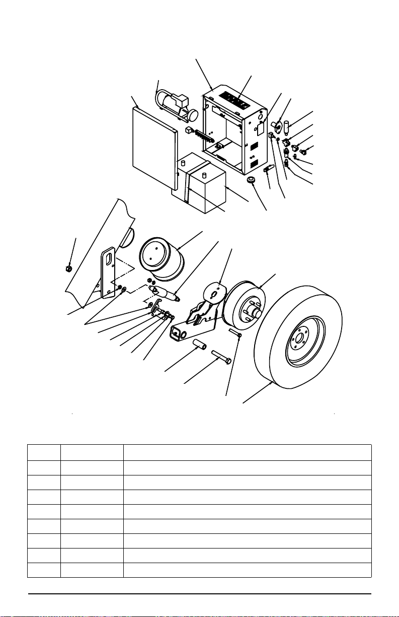
4.0 Repair Parts
13
13
14
26
8
46
40
29
70
1
8
14
51
53
66
67
12 11
55
68
10
27
2330
46
28
52
28 52
28
52
69
7
71
7
47
72
73
**Lift Mechanism
*
Figure 4-1. MAS-M
*See Figure 4-2 Details A-D for gate hardware (item 14).
**See Figure 4-2 Detail E for lift mechanism parts.
24 MAS-M Operator’s Manual
Page 29

Key Part No. Description
131436 Weigh Center w/ Indicator (see Operator’s manual PN 159192)
1
126788 Plug Plastic Round 1-1/8”
7
126787 Scale T-belting (83” width)
8
127740 Cover Plate Scale Frame/J-box
10
126819 Foam Gasket J-box
11
131891 Scale Junction Box 4 Cell SS
12
130931 Cage Cross-member
13
131782 Gate Short Sheeted
14
126951 Bolt Carriage 5/16 x 1/2 Round Head Grade A Zinc
23
131708
26
131946
131708
27
131947
127168 Pin, Hitch Pivot
28
130567 Frame, 13’
29
130773 Frame, 18’
126950 Nut 5/16 Flanged Serrated
30
130022 Operator Shield
40
45728 Screw, Self Drilling 12-24 x 7/8
131707 Cage Floor MAS-M, 13’
46
131934 Cage Floor MAS-M, 18’
15097 Bolt, 3/4-10NC x 3 1/2 Hex Head, Grade 5 Zinc
47
14697 Nut, Lock, 3/4-10NC Hex, Nylon Insert Zinc
127716 Jack w/ Drop Leg and Mount
51
126966 Hair Pin
52
127715 Hitch Coupler Mobile MAS
53
106387 Bumper
55
131896 Hitch Member Right
66
131900 Hitch Member Left
67
132692 Label MAS-M Weigh/Transport Mode
68
127094 Label MAS-M Transport/Weigh Mode
69
127721 Battery Box w/ compressor and wiring
70
127098 Transportation Position Decal
71
131955 Safety Chain
72
130842 Rice Lake Decal
73
127727 Standard Hitch Cable w/Connectors
N/S
127090 Label Basic Operating Instructions
N/S
Cage Wall 13’
Cage Wall 18’ Right
Cage Wall 13’
Cage Wall 18’ Left
Repair Parts 25
Page 30

34
'HWDLO'
'RRU+DUGZDUH/DWFK
45
19
22
42
36
20
'HWDLO%
'RRU+DUGZDUH+LQJH
13 15
33
24
14
'HWDLO$
'RRU+DUGZDUH/DWFK6LGH
18
20
56
19
'HWDLO(
/LIWLQJ0HFKDQLVP
9
17
2
3
6
57
58
59
60
61
16
16
58
65
62
63
64
'HWDLO&
'RRU+DUGZDUH+LQJH6LGH
43
44
35
42
26 MAS-M Operator’s Manual
Figure 4-2. MAS-M Details
Page 31

Key Part No. Description
127184 Upper Notched Load Cell Pin
2
21444 Load Cell S-Type 10K
3
127163 Eyebolt Machined 10K
127668 Lower Load Cell Retainer
6
127200 Load Cell Cam Stand Cover SS
9
127007 Bolt 1/4x1/2
151807 Washer, Plain 3/4in Nylon
13
110950 Pin, Spring 1/4 x 1 1/4
14
151589 Hinge Hanger Bolt Hook
15
127684 Plug Plastic Round 2”
16
127177 Lower Notched Load Cell Pin
17
126926 Pin Spring Slotted 1/4x2-1/4
127033 Cap Screw, 3/8-16 x 3/4
18
15159 Washer, 3/8 Lock
19
132684 Nut, 3/8-16 Grade5
20
131784 Gate Latch
22
127021 Hair Pin 1/8 x 2 9/16
15181 Washer, 3/4
24
132179 Hinge Bracket
31
111074 Nut, 3/4-10NC
33
132217 Jam Nut, 3/4-10NC
34
21939 Washer, 5/16
35
131886 Cable, 1/4” OD x 6 ft
36
71872 Bolt, 3/4-10NC x 4
37
14697 Nut, Lock 3/4-10NC
39
131887 Quick Link 1/4 in
42
131701 Eye Bolt, 5/16-18 x 2 1/2
43
14646 Nut, Lock 5/16-18NC
44
39528 Bolt, 3/8-16NC x 2 1/4
45
132427 Strike Plate
56
131787 Cam with Lockdown
57
127165 Spacer Upper Notched Pin
58
127732 Cam Handle
59
131785 Cam Without Lockdown
60
15167 Lockwasher ½
61
14765 Bolt 1/2 x 4
127561 Scale Cable Female MS Conn 132”
22093 Bolt 3/8 x 2 Grade5
62
15161 Flat washer 3/8 SS SAE
63
126992 Nut 3/8 SS
64
128626 Scale Damper Assembly w/Bushings
65
Repair Parts 27
Page 32
47
48
49
50
51
52
53
54
55
56
57
58
59
60
61
62
63
64
65
81
80
79
78
77
76
75
74
73
72
71
70
69
68
67
66
Key Part No. Description
47 127171 Door Assembly Battery Box
48 127414 Air Compressor 12V, 1 CFM
49 127170 Battery housing
50 128266 Label “Not for Transportation ….”
51 131015 Label Hitch Plug Wiring
52 127393 6 Way Round Trailer Receptacle
53 127406 Relief Valve Air 150 PSI
54 126900 4FP Brass Cross
28 MAS-M Operator’s Manual
Figure 4-3. Battery Box and Tire/Wheel Parts
Page 33

Key Part No. Description
55 127070 Brass Tee Forger 4FP
56 126891 Valve Brass Drain Cock
57 127399 Valve Air Tank w/ Core and Cap
58 126901 Fitting Brass 4FP Terminal Bolt
59 126902 Fitting Brass 4MP to ¼ Synflex
60 128108 Switch Seal Hex
61 127398 Switch ON/OFF
62 127289 Latch SS Pull Up
63 126944 Grommet 1-3/8 x 1/4
64 127106 Battery Deep Cycle Marine
127402 Terminal Block 6 Pole
127397 Relay Headlight 12v
127076 Circuit Breaker 12V 30 Amp
65 127073 Strap 1” with Clasp
66 14697 Nut Lock Nylon ¾
67 126936 Nut Jam ½
68 127046 Washer 7/16 USS
69 127334 Suspension Stop Arm
70 127178 Bushing Suspension Stop
71 15179 Washer ¾ SAE
72 15167 Lock washer ½
73 14768 Bolt ½ x4-1/2
74 127169 Bushing Pivot Axle
75 14788 Bolt ¾ x 5
76 14757 Bolt ½ x 3
77 127129 Tire and Rim ST175/80R13
78 132389 Hub and Drum, Dexter 3500# Axle w/ 10x2.5 Brakes
132387 Left Dexter 3500# Axle w/ 10x2.5 Brakes
132388 Right Dexter 3500# Axle w/ 10x2.5 Brakes
79 127718 Axle Arm Left
127719 Axle Arm Right
80 127745 Suspension Shock Absorber
81 127405 Air Spring 2B8-550
127069 Ball Valve, Miniature
82133 Nipple, Pipe 1/4NTP x 3
Repair Parts 29
Page 34
5.0 Maintenance
Grease zerk
on gate
latches
Grease zerk
at axle pivot
5.1 Maintenance Schedule
Before Each Use
1. Grease axle pivot locations, using the provided grease zerks (see Figure 5-1),
using a “Black Moly” type grease.
First Week
1. Check torque on all wheel nuts (see Section 5.3.4 on page 33).
Weekly
1. Check entire scale for buildup of debris. Remove any debris found on, under or
around the scale. Rubber T-belting at both ends of the scale are removable to
make clean out easier. To remove T-belting, unhook the stretch cord that hooks
into the corner tube of the cage.
2. Check for dirt and debris in the load cell stands and clean accordingly.
3. Check all external cables and conduit for damage.
First Month (in addition to weekly maintenance)
1. Check torque on all wheel nuts (see Section 5.3.4 on page 33).
2. Adjust scale brakes.
Monthly (in addition to weekly maintenance)
1. Charge scale battery if necessary.
2. Tire Pressure. 45 psi./40psi. - Single /Tandem Axle
3. Grease gate latch zerks (see Figure 5-1) using a “Black Moly” type grease.
Yearly (in addition to weekly and monthly maintenance)
1. Check and grease wheel bearings (see Section 5.3.5 on page 33).
2. Disassemble each load cell location and grease all pins and eye bolts (see
Section 5.2.2 on page31).
3. Adjust scale brakes (see Section 5.3.3 on page 32).
30 MAS-M Operator’s Manual
Figure 5-1. Grease Zerk Locations
Page 35
5.2 Scale Maintenance Procedures
Note
26
27
28
35
36
33
37
38
39
40
34
5.2.1 Cleaning Load Cell Stands
It is very important to keep any excess debris from building up in t he load cell stand.
Lift scale and block it up, clean any dirt out of the load cell stands through the drain
holes located at the bottom of the stand.
5.2.2 Disassembly and Greasing
This is very important to ensure the long life of the unit. Use the parts list drawings
for item numbers.
Use quality high-pressure grease.
Avoid bending or twisting the load cell wires.
a. Remove the cell stand cover (27).
b. Remove the plug covers (34)
c. Remove the bolt which holds together items 26, 39, 38.
d. While holding the cam handle (36), remove the outer cam (38).
e. Remove the load cell pin (37) and spacers (35). The load cell assembly will be
free on top and rest against the inside of the cell stand.
f. Remove the inner cam (26).
g. Remove the lower retainer (33)
h. Grease all bearing surfaces except where the eyebolt contacts the pin (upper and
lower pins, cams, upper and lower eyebolts).
i. Reassemble in reverse order as described above.
Figure 5-2. Disassembly and Greasing
Maintenance 31
Page 36

5.3 Scale Maintenance Procedures
WARNING
Note
5.3.1 How to Use The Electric Brakes Properly
The scale brakes are designed to work in synchronization with the tow vehicle brakes.
Never use the tow vehicle or scale brakes alone to stop the combined load.
The brake controller must be set up according to the manufacturer's recommendations
to ensure proper synchronization between the tow vehicle and the scale. Additionally,
you may have to make small adjustments occasionally to accommodate changing
loads and driving conditions.
Proper synchronization of tow vehicle to scale braking can only be accomplished by
road testing. Brake lockup, grabbing, or harshness is quite often due to the lack of
synchronization between the tow vehicle and the scale being towed, too high of a
threshold voltage (over 2 volts), or under adjusted brakes.
The following should only be performed in a safe environment
such as an unpopulated road free of traffic or under controlled
conditions.
Before any synchronization adjustments are made, the scale brakes should be
burnished-in by applying the brakes 20-30 times with approximately a 20 m.p.h.
decrease in speed, e.g. 40 m.p.h. to 20 m.p.h. All ow ample time for brakes to cool
between application. This allows the brake shoes and magnets to slightly "wear-in" to
the drum surfaces.
5.3.2 Synchronizing The Scale Brakes
To ensure safe brake performance and synchronization, read the brake controller
manufacturer's instructions completely before attempting any synchronization
procedure.
Make several hard stops from 20 M.P.H. on a dry paved road free of sand and gravel.
If the scale brakes lock and slide, decrease the gain setting on the controller . If they do
not slide, slightly increase the gain setting. Adjust the controller just to the point of
impending brake lockup and wheel skid.
Not all scale brakes are capable of wheel lockup. Loading conditions,
brake type, wheel and tire size can all affect whether a brake can lock. It
is not generally considered desirable to lock up the brakes and slide the
tires. This can cause unwanted flat spotting of the tires and could also
If the controller is applying the scale brakes before the tow vehicle brakes, then the
controller adjustments should be made so the scale brakes come on in synchronization
with the tow vehicle brakes. For proper braking performance it is recommended that
the controller be adjusted to allow the scale brakes to come on just slightly ahead of
the tow vehicle brakes. When proper synchronization is achieved there will be no
sensation of the scale “jerking” or “pushing” the tow vehicle during braking.
result in a loss of control.
5.3.3 Brake Adjustment
Brakes should be adjusted (1) after the first 200 miles (first month) of operation when
the brake shoes and drums have “seated,” (2) at 3,000 mile intervals (or yearly), (3) or
as use and performance requires. The brakes should be adjusted in the following
manner:
1. Jack or block the axle arm to allow free rotation of the wheel.
2. Remove the adjusting hole cover from the adjusting slo t on the bottom of the
brake backing plate.
32 MAS-M Operator’s Manual
Page 37
3. Rotate the star wheel of the adjuster assembly with a screwdriver or standard
adjusting tool to expand the brake shoes. Adjust the brake shoes out until the
pressure of the linings against the drum makes the wheel very difficult to turn.
4. Then rotate the star wheel in the opposite direction until the wheel turns
freely with a slight lining drag.
5. Replace the adjusting hole cover and lower the wheel to the ground.
6. Repeat the above procedure on all brakes. For best results the brakes
should all be set at the same clearance.
5.3.4 Wheel Assembly and Torque Specification
1. Start all bolts or nuts by hand to prevent cross threading.
2. Tighten bolts or nuts in the sequence shown below.
3. The tightening of the fasteners should be done in st ages, per torque chart below
following the recommended sequence.
4. Wheel nuts/bolts should be torqued before first road use and after each wheel
removal. Check and re-torque after the first 10 miles, 25 miles, and again at 50
miles.
1st Stage 2nd Stage 3rd Stage
20-25 50-60 90-120
Table 5-1. Wheel Torque Sequence (ft-lbs)
Figure 5-3. Wheel Torque Sequence
5.3.5 Bearing Adjustment
In the event the hub is removed follow this procedure for wheel bearing adjustment.
1. After placing the hub, bearings, washers, and spindle nut on the ax le spindle
rotate the hub assembly slowly while tightening the spindle nut to
approximately 50 lbs.-ft.
2. Then loosen the spindle nut to remove the torque. Do not rotate the hub.
3. Finger tighten the spindle nut until just snug.
4. Back the spindle nut out slightly until the first castellation lines up with the
cotter key hole and insert the cotter pin
5. Bend over the cotter pin legs to secure the nut.
6. The nut should be free to move with the only restraint being the cotter pin.
7. Install the dust cover and rotate the wheel to ensure the cotter key does not
contact the dust cover.
Maintenance 33
Page 38
5.3.6 Axle Parts
27 1/2”
90”
89 1/4”
87 1/4”
10
6
1 1/2” OD
2 x 2 TUBING
Axles are Dexter 3500lb, 5-bolt with 10x2-¼” brakes.
Following are replacement parts available from Dexter.
Bearings
Dexter Kit # Industry Part # Cup/Cone
Inner K71-390-00 L68111 / L68149
Outer K71-306-00 L44610 / L44649
Description Dexter Part #
Inner Bearing Seal 010-004-00
Magnet K71-104-00
Brake Shoe and Lining K71-047-00
Brake Assembly LH 023-026-00
Brake Assembly RH 023-027-00
Hub 008-247-05
5.4 Gathering Panel Attachment
Suggested Construction
34 MAS-M Operator’s Manual
Figure 5-4. Gathering Panel Frame
Page 39
Building a simple framework that can be set into the provided scale posts can
CAUTION
accommodate mounting of most any panel. In some cases extra support of the
mounting frame may be required.
Figure 5-4 shows the suggested construction of a framework you can build to support
the type of gathering panels you have. Some gathering panels can be set directly into
the corner posts located on the corners of the scale and require only a shortened
version of the drawing above that can be set into the top of the panels. (See Figure 5-
5) However, with the wide variety of panels available we cannot provide a mounting
means for all of them.
However you decide to mount you panels you must ensure the panels or framework
are not attached to the scale cage and must have a clearance of 1" from any live
portion of the scale. Any contact between the panels or framework and the scale can
cause the weight reading to be inaccurate.
Figure 5-5. Gather Panel Attachment
Gathering Panel Warranty Information
Gathering panels or handling attachments must be removed from
the scale during transport. The scale is not intended for the
transportation of goods or livestock.
The design of the scale only allows for 100 pounds to be added to
either end of the scale, for a MAXIMUM addition of 200 pounds,
during transport. All attachments that will remain on the scale
must not exceed the weight limit of 100 pounds on the front and/
or 100 pounds on the rear. If the total of the attachments on either
the front or the rear exceeds 100 pounds the warranty will be
void.
Any additions to the scale may affect the balance and towability
of the scale.
Any attachments to the scale must be secured during transport
and not interfere with any safety device or the operation scale
mechanisms.
Maintenance 35
Page 40
5.5 Wiring Diagrams
Load Cell #1
Load Cell #2
Load Cell #4
Load Cell #3
Scale Cable
Junction Box
Trimmers
Load Cell #4
Load Cell #1
Load Cell #2
Load Cell #3
Indicator
Black
Green
White
Shield
Red
+E
-E
+S
-S
GND
V1 V2 V3 V4
Load cell wiring shown is effective for all
models later than 09/17/2013, models
built prior to that date should rewire the
scale to the updated configuration. For
information on rewire download Technical
Bulletin PN 159193 from www.ricelake.com.
Note
DA
B
Indicator
AD
CB
Scale
A -EXC Black
B +SIG Green
C +EXC Red
D -SIG White
Connector
C
7 WAY TRAILER CONNECTOR
Reverse Lights
12V Battery Power
Right Turn & Brake
Brake Controller Output
Tail & Running Lights
(7) Purple
(
4) Black
(6) Green
(2) Red
(3) Brown
(5) Yellow
Left Turn & Brake
(1) White
Ground
Figure 5-7. Scale/Indicator System Connection
Figure 5-6. Load Cell Wiring Diagram
36 MAS-M Operator’s Manual
Figure 5-8. Electrical Connection
Page 41
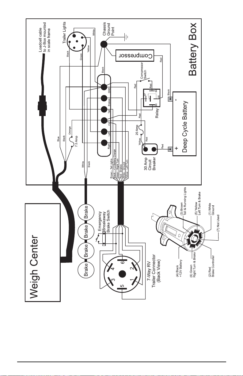
Figure 5-9. System Wiring Diagram
Maintenance 37
Page 42

5.6 Specifications
t
N
A
T
I
O
N
A
L
C
O
N
F
E
R
E
N
C
E
t
O
N
W
E
I
G
H
T
S
A
N
D
M
E
A
S
U
R
E
S
Size / Model # ___________________________
Serial # _________________________________
Date Purchased _________________________
Unit ID # _______________________________
MAS8-13 MAS8-18
Length Overall 18’-8” 24’-5”
Length Deck 12’-9” 18’-6”
Width Overall 8’-6” 8’-6”
Width Deck 7’-5” 7’-5”
Deck Height 6” 6”
Height 99” 99”
Deck Covering 5/8” Recycled Molded Rubber Flooring System
Weight 3100 lbs. 4600 lbs.
Capacity 15000 lbs. 20000 lbs.
Section Cap 10000 lbs. 20000 lbs.
Approval Class IIIL (IIIHD) IIIL (IIIHD)
Approvals
Grad Size 5 lb (2 kg) 5 lb (2 kg)
**Paint Powder Coated Galvanized Steel
Tire Pressure 50 PSI 45 PSI
Wheel size 13” 5 on 4.5” 13” 5 on 4.5”
Tire Size ST175/80R13 ST175/80R13
Lug Torque 90-120 ft-lbs 90-120 ft-lbs
Battery 12V Deep Cycle 12V Deep Cycle
**Structural Steel is not galvanized.
38 MAS-M Operator’s Manual
99-091A4
AM4*
Page 43

5.7 Towing Checklist
Each item of checklist to be reviewed and list to be signed by dealer and customer at
delivery.
[ ] Operator Safety section of manual has been reviewed.
[ ]
Scale is not intended for the transport of livestock or any other
goods or materials.
[ ] Ball on towing vehicle must be 2”
[ ]
Hitch height of towing vehicle must be between approximately
16” above the ground such that the scale is in towing level.
[ ] Safety chains must always be connected during towing.
[ ] Towing vehicle must be wired correctly (see label on hitch)
[ ] Magnetic lighting package must be on the scale during towing.
[ ]
Scale is equipped with electric brakes and must be
synchronized. See synchronization procedure in manual.
[ ]
Scale is designed to be towed at a ride height indicated by
labels
outside of the indicated range may result in suspension damage.
[ ] Suspension stops must be in the transport position during towing.
[ ]
Converting the scale from weigh mode to transport mode and
back to weigh mode has been reviewed.
on the suspension shock absorbers. Towing at ride heights
[ ] Safety pins are installed in all the hitch pins.
[ ]
Dexter recommends to re-torque wheel lug nuts at 10, 25 and
50
miles.
Buyer ________________________Date_________________ __
Dealer ________________________
Copy to be retained by dealer
Fax copy to manufacturer: Fax #:
715-234-6967
Maintenance 39
Page 44

Mobile Group Limited Warranty
Rice Lake Weighing Systems (RLWS) warrants that all RLWS equipment and
systems properly installed by a Distributor or Original Equipment Manufacturer
(OEM) will operate per written specifications as confirmed by t he Distributor/OEM
and accepted by RLWS. All systems and components are warranted against defects in
materials and workmanship for two years.
RL WS warrants that the equipment sold hereunder will conform to the current written
specifications authorized by RLWS. RLWS warrants the equipment against faulty
workmanship and defective materials. If any equipment fails to conform to these
warranties, RLWS will, at its option, repair or replace such goods returned within the
warranty period subject to the following conditions:
• Upon discovery by Buyer of such nonconformity, RLWS will be given
prompt written notice with a detailed explanation of the alleged
deficiencies.
• Individual electronic components returned to RLWS for warranty
purposes must be packaged to prevent electrostatic discharge (ESD)
damage in shipment. Packaging requirements are listed in a publication,
Protecting Your Components From Static Damage in Shipment, available
from RLWS Equipment Return Department.
• Examination of such equipment by RLWS confirms that the
nonconformity actually exists, and was not caused by accident, misuse,
neglect, alteration, improper installation, improper repair or improper
testing; RLWS shall be the sole judge of all alleged non-conformities.
• Such equipment has not been modified, altered, or changed by any person
other than RLWS or its duly authorized repair agents.
• RLWS will have a reasonable time to repair or replace the defective
equipment. Buyer is responsible for shipping charges both ways.
• In no event will RLWS be responsible for travel time or on-location
repairs, including assembly or disassembly of equipment, nor will RLWS
be liable for the cost of any repairs made by others.
THESE WARRANTIES EXCLUDE ALL OTHER WARRANTIES, EXPRESSED OR IMPLIED,
INCLUDING WITHOUT LIMITATION W ARRANTIES OF MERCHANTABILITY OR
FITNESS
IN ANY EVENT, BE LIABLE FOR INCIDENTAL OR CONSEQUENTIAL DAMAGES.
RLWS
HEREUNDER
ACCEPTING
TO
S
TO
N
MODIFY
MADE
BUYER.
FOR A PARTICULAR PURPOSE. NE ITHER RLWS NOR DISTRIBUTOR WILL,
AND BUYER AGREE TH AT RLWS’ SOLE AND EXCLUSIVE LIABILITY
IS LIMITED TO REPA I R OR REPLACEMENT OF SUCH GOODS. IN
THIS WARRANTY, THE BUYER WAIVES ANY AND ALL OTHER CLAIMS
WARRANTY.
HOULD THE SELLER BE OTHER THAN RLWS, THE BUYER AGREES TO LOOK ONLY
THE SELLER FOR WARRANTY CLAIMS.
O TERMS, CONDITION S, UNDERSTANDING, OR AGREEMENTS PURPORTING TO
THE TERMS OF THIS WARRANTY SHALL HAVE ANY LEGAL EFFECT UNLESS
IN WRITING AND SIGNED BY A CORPORATE OFFICER OF RLWS AND THE
© Rice Lake Weighing Systems, Inc. Rice Lake, WI USA. All Rights Reserved.
RICE LAKE WEIGHING SYSTEMS • 230 WEST COLEMAN STREET
RICE LAKE, WISCONSIN 54868 • USA
40 MAS-M Operator’s Manual
Page 45

For More Information
Web Site
Frequently Asked Questions (FAQs) at
http://www.ricelake.com/faqs.aspx
Contact Information
Hours of Operation
Knowledgeable customer service representatives are available 6:30 a.m. - 6:30 p.m.
Monday through Friday and 8 a.m. to 12 noon on Saturday. (CST)
Telephone
• Sales/Technical Support 800-472-6703
• Canadian and Mexican Customers 800-321-6703
• International 715-234-9171
Immediate/Emergency Service
For immediate assistance call toll-free 1-800-472-6703 (Canadian and Mexican
customers please call 1-800-321-6703). If you are calling after standard business
hours and have an urgent scale outage or emergency, press 1 to reach on-call
personnel.
Fax
Fax Number 715-234-6967
E-Mail
• US sales and product information at
prodinfo@ricelake.com
• I nternational (non-US) sales and product information at
intlsales@ricelake.com
Mailing Address
Rice Lake Weighing Systems
230 West Coleman Street
Rice Lake, WI 54868 USA
Maintenance 41
Page 46

Notes
42 MAS-M Operator’s Manual
Page 47

Page 48

230 W. Coleman St. • Rice Lake, WI 54868 • USA
U.S. 800-472-6703 • Canada/Mexico 800-321-6703 • International 715-234-9171 • Europe +31 (0) 88 2349171
www.ricelake.com www.ricelake.mx www.ricelake.eu www.ricelake.co.in m.ricelake.com
© Rice Lake Weighing Systems 02/2014 132051 Rev E
 Loading...