

Page 1
MagnaMount
W eigh Module Kit
Installation
Guide
®
25707
Page 2

Contents
1. Introduction........................................................................................ 1
2. Parts Assembly .................................................................................. 2
2.1 Assembling the Base Plate ........................................................ 2
2.2 Assembling the Retaining Plate ................................................. 3
2.3 Assembling the Dummy Load Cell .............................................4
3. Mechanical Installation..................................................................... 6
3.1 General Installation Guidelines .................................................. 6
3.2 Maintaining Scale Height and Center.........................................6
3.3 Mount and Installation Procedures.............................................7
3.3.1 Positioning and Leveling the Mount, and Securing the ...............
Retaining Plate..........................................................................7
3.3.2 Securing Lateral Restraints.......................................................7
3.3.3 Re-leveling, Securing, Grouting, and Grounding the Base ....... 8
3.3.4 Installing the Load Cell..............................................................9
3.3.5 Removing the Load Cell............................................................9
4. Load Cell Wiring .............................................................................. 10
5. Junction Box Connections, Adjustments & Calibration .................. 11
6. Troubleshooting................................................................................ 11
7. Replacement Parts...........................................................................12
8. Appendix—Mount Dimensions........................................................ 14
9. Limited Warranty..............................................................................15
Copyright © 1999 Rice Lake Weighing Systems. All rights
reserved. Printed in the United States of America.
Specifications subject to change without notice.
11/99
Page 3

1. Introduction
The MagnaMount® weigh module provides an accurate method of weighing heavycapacity tank, truck, and railroad track weighing applications. The mount is
available in three heavy-duty capacities: 50,000 lb, 100,000 lb, and 200,000 lb. The
load bearing plate is constructed of high-grade carbon steel, which gives the mount
its high-strength capabilities. The unique Teflon®-coated load bearing plate permits
multi-directional movement to offer accurate weighing and compensate for temperature variations. The mount shields the load cell on four sides to protect it from
shock and side loads.
RTICSP1, RTICP1, and RLCSP1 compression canister loads cells are compatible
for use in the MagnaMount. All are constructed of stainless steel, hermetically
sealed, and rated for 150% maximum overload.
The installation should be planned by a qualified structural engineer. Each installation is unique, and this manual is meant to serve only as a general guideline for
installation.
Authorized distributors and their employees can view or
download this manual from the Rice Lake Weighing
Systems distributor site at www.rlws.com
Teflon® is a registered trademark of E.I. Dupont
1
Page 4

2. Parts Assembly
The MagnaMount can be assembled as one unit and hoisted into place on the
foundation, or it can be assembled part by part onto the foundation. This section
describes the assembly of the mount into one unit.
2.1 Assembling the Base Plate
1. Screw the four leveling bolts into the base plate.
2. Place the two corner stands on the base plate (see graphic below).
3. Place the flexure plate over the two corner stands.
4. Place the two anchor blocks on top of the flexure plate in line with each
corner stand.
5. Screw anchor bolt through the anchor blocks, flexure plate, and corner
stands to the base plate using the eight anchor block bolts and washers
(only six anchor block bolts and washers for the 100,000 lb capacity mount
and only four for the 50,000 lb).
6. Torque the anchor block bolts to spec (see torque value table, page 4).
Base Plate Assembly
2
Anchor Bolt
Flat Washer
Anchor Block
Flexure Plate
Stand
Leveling Bolt
Base Plate
50K—5/8"—11 x 6"
100K—3/4"—10 x 9"
200K—1"—8 x 12"
50K—5/8"
100K—3/4"
200K—1"
50K—5/8"—11 x 3"
100K—5/8"—11 x 3"
200K—7/8"—9 x 5-1/4"
Page 5
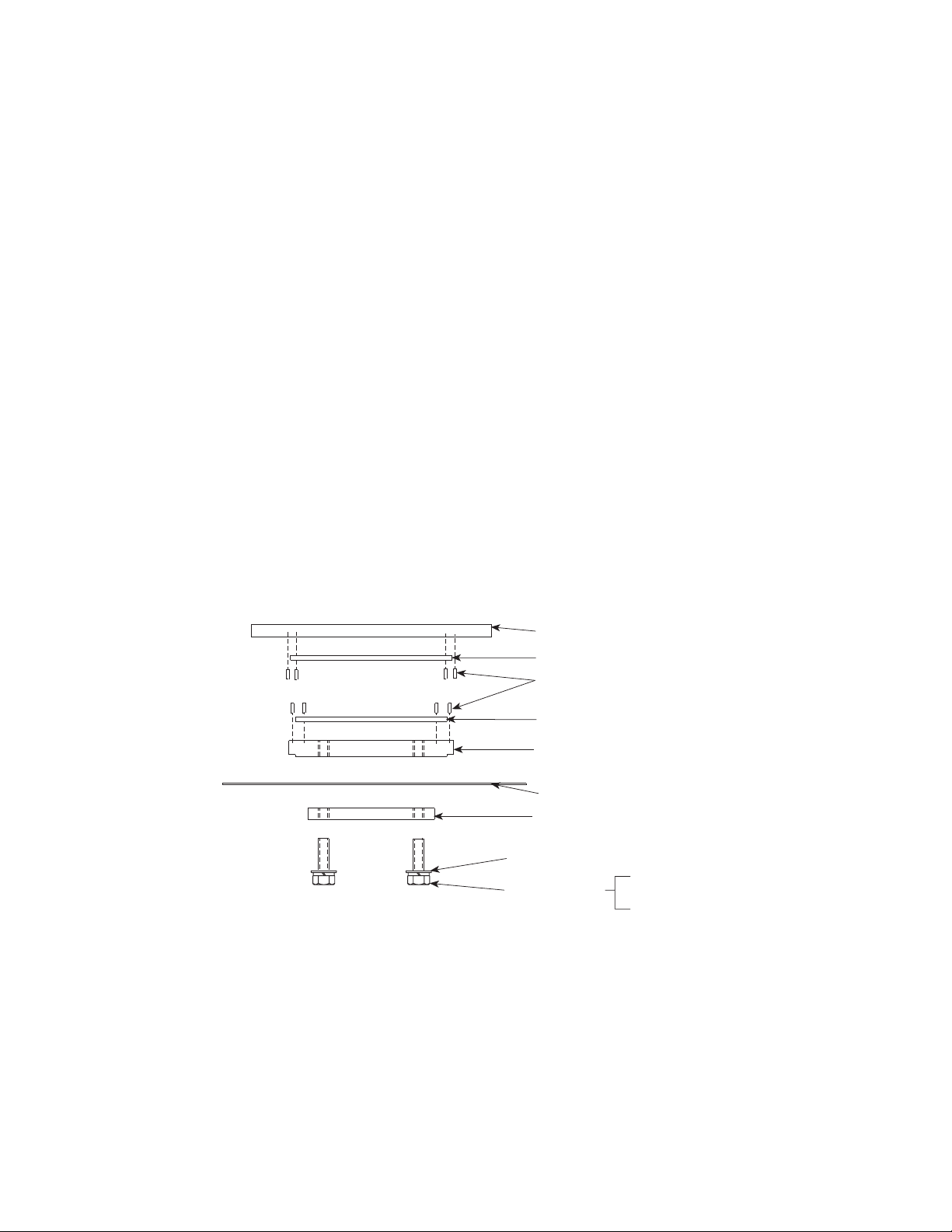
2.2 Assembling the Retaining Plate
1. Install tension pins 1/4" x 3/4" in retaining plates and bottom plates. Leave
1/4" out of plates.
2. Place the bottom plate on top of the flexure plate (see graphic below).
3. Position the top mounting plate under the flexure plate aligned with the
bottom plate.
4. Screw the top mounting plate to the bottom plate using the top mounting
plate bolts, lockwashers, and washers.
5. Torque the top mounting plate bolts to spec ( see torque value table, page 4).
Note:
The top mounting plate is on the bottom of this assembly and on top of
the load cell.
6. Place the bottom fabreeka pad on the bottom plate.
7. Place the top fabreeka pad on the bottom Fabreeka® pad.
8. Place the retaining plate on top of the top Fabreeka pad.
Retaining Plate
Top Fabreeka Pad
Tension Pin
Retaining Plate Assembly
Fabreeka® is a registered trademark of Fabreeka International Inc.
3
15
Bottom Fabreeka
Bottom Plate
Flexure Plate
Top Mount Plate
Top Mount Washer
Top Mount Bolt
50K—5/8"—11 x 1-1/4"
100K—1-3/4"—10 x 1-3/4"
200K—1"—8 x 2-1/2"
1/2"—13 x 2"
Page 6

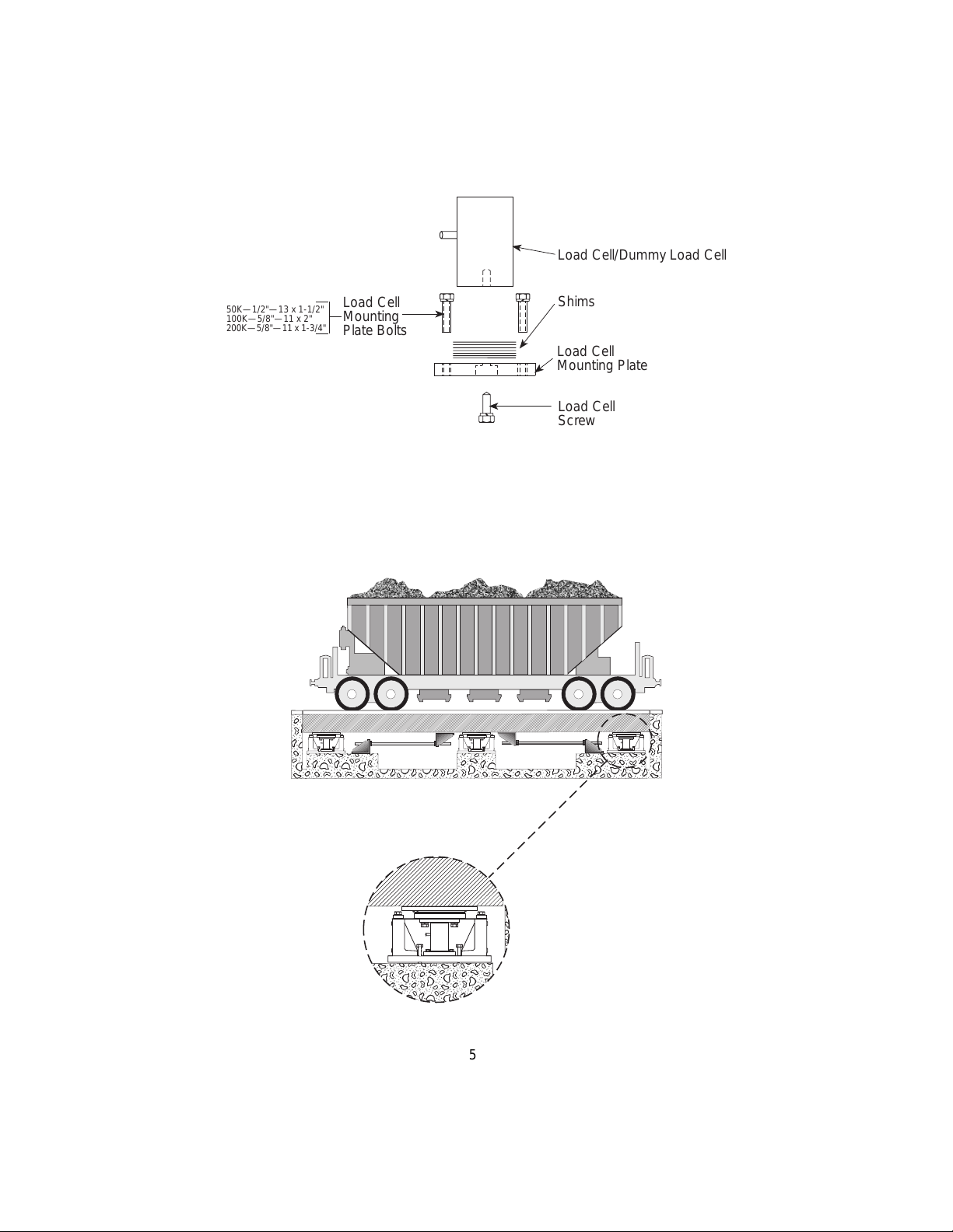
2.3 Assembling the Dummy Load Cell
1. Place nine shims on the load cell mounting plate (only four shims for the
100,000 lb capacity mount and only six for the 50,000 lb).
2. Place the dummy load cell on the shims (see load cell assembly graphic).
3. Screw the load cell screw into the dummy load cell from the bottom of the
load cell mounting plate.
4. Insert the dummy load cell assembly in the mount between the base plate
and the top mounting plate. Add or subtract shims so top of dummy cell just
touches the top mounting plate with no load.
5. Screw the load cell mounting plate bolts with lockwashers into the base
plate.
6. Torque the load cell mounting plate bolts to spec. See the following table
for all necessary torque values.
elbaTeulaVeuqroT
sbL/tFnieuqroTdednemmoceR
retemaiDtloB
"4/1901
"61/58102
"8/35353
"61/75506
"2/10809
"61/9011031
"8/5071081
"4/3082023
"8/7064005
"1086047
"8/1-10690801
"4/1-106310051
"8/3-108710402
"2/1-106320662
CNU FNU
.detacirbul8edargroferaseulaV:etoN
Note:
After the mount is fully installed on the foundation and the scale deck I-beam is
secured to the mount, the dummy load cell can be replaced by the actual load cell.
Refer to Section 3.3.4, Installing the Load Cell and Section 3.3.5 Removing the
Load Cell.
4
Page 7
a
a
a
a
a
a
a
aa
a
aa
aaa
a
a
a
a
a
a
a
aa
a
a
aa
a
a
a
a
a
aa
a
a
a
a
a
a
aa
a
a
a
a
a
a
a
a
a
a
a
a
a
a
a
aa
a
a
a
a
a
a
a
a
a
a
a
a
a
a
a
a
a
a
aa
a
a
a
a
a
a
a
a
a
a
a
a
a
a
a
a
a
a
a
a
a
a
a
a
a
a
a
a
a
a
a
a
aa
a
a
aa
a
a
a
a
a
aaa
a
a
Load Cell/Dummy Load Cell
50K—1/2"—13 x 1-1/2"
100K—5/8"—11 x 2"
200K—5/8"—11 x 1-3/4"
Load Cell
Mounting
Plate Bolts
Shims
Load Cell
Mounting Plate
Load Cell
Screw
Load Cell Assembly
Typical configuration of foundation, mount, and scale deck I-beam
5
13
Page 8
3. Mechanical Installation
Mechanical installation consists of positioning the mount on a foundation, leveling
the mount for weighing accuracy, securing the mount to the foundation and scale
deck I-beam, and grouting.
3.1 General Installation Guidelines
1. Install a system ground in the pit in close proximity to the junction box. Use
at least 1/2" x 8' copper clad ground rod. Hook the indicator, junction box,
scale deck I-beam, load cell grounding straps, and lightening protection
devices to the system ground. Hook all other devices, such as the printer,
to the same AC power supply as the indicator.
2. Proper drainage must be provided so that the weighing assembly is not
standing in water. Also, drainage loops should be provided on any conduit
or cables going to the junction box or load cell.
3. The mount must be positioned in the direction of travel (see Mount Orientation). Also,
the load on each mount assembly should be
equal to each other.
4. Check rods must be installed (see Check
Rod illustrations on following page). Consult the supervising engineer for proper
placement and stability.
Direction of travel
5. The mounting surface for the base and loading plate must be level and parallel with pier
and I-beam. Shim as necessary. The mount
assemblies must be plumb and level within ±0.2°.
6. The dummy load cell should remain in the mount until all mechanical work
is finished. The load cell should never be in the mount when any welding
is done.
Mount Orientation
3.2 Maintaining Scale Height and Center
Whether replacing existing scales or installing new load cell mounts, you need to
maintain the final height of your scale system.
1. On the concrete pier foundations, install blocking to hold up the scale deck
I-beam and platform to the required height for normal truck scale operation. Place wedges between the platform and the pit’s edges to center the
platform.
2. Remove the existing scales and/or install the new mounts one at a time to
continue to maintain the proper height. Installation procedures follow this
section.
6
Page 9

3.3 Mount and Installation Procedures
3.3.1 Positioning and Leveling the Mount, and Securing the
Retaining Plate
1. Start with a flat, rigid foundation (concrete pier). Using a forklift, position
the mount onto the foundation. Align the base plate in the direction of
travel (see page 6).
Note:
Leveling is the single most important part of the installation for
achieving high-accuracy weighing.
2. Adjust the leveling bolts to bring the top of the retaining plate up so it is
flush with the bottom of the scale deck I-beam. Check to see whether the
retaining plate is centered longitudinally with the scale deck I-beam and
adjust the mount if necessary. Place shims between the top of the retaining
plate and the bottom of the scale deck I-beam, because the scale deck Ibeam is never even. The shims should cover the entire surface to prevent
bending. If necessary, adjust the leveling bolts to insert the shims.
3. Using a high-quality bubble level, level the base plate within 0.2° of
horizontal to achieve a scale accuracy of 0.1% or better.
4. Mark the retaining plate hole locations on the scale deck I-beam (see
appendix for retaining plate hole dimensions).
5. Remove the load cell mount while noting the placement and height of the
shims.
6. With a magnetic drill, drill the holes into the scale deck I-beam.
7. Replace the mount and the shims. Bolt the retaining plate to the scale deck
I-beam. Retaining plate bolts are not supplied.
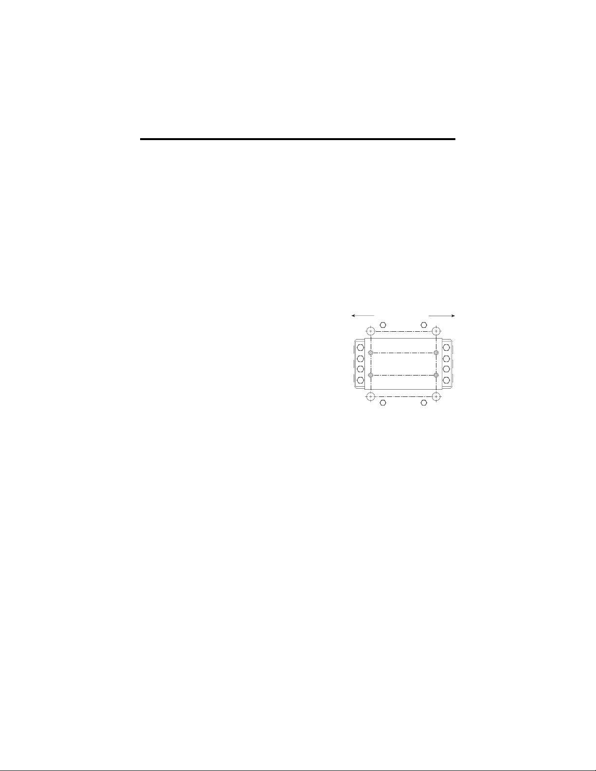
3.3.2 Securing Lateral Restraints
Lateral restraints (check rods) must be installed between each mount.
1. Install the check rods between each mount (see page 8). These lateral
restraints create a rigid mount system for heavy loading conditions. The
check rods should be positioned as close to each mount as possible. The rod
should be at least 4' to 6' long. Spherical washers should be used with each
nut.
7
11
Page 10
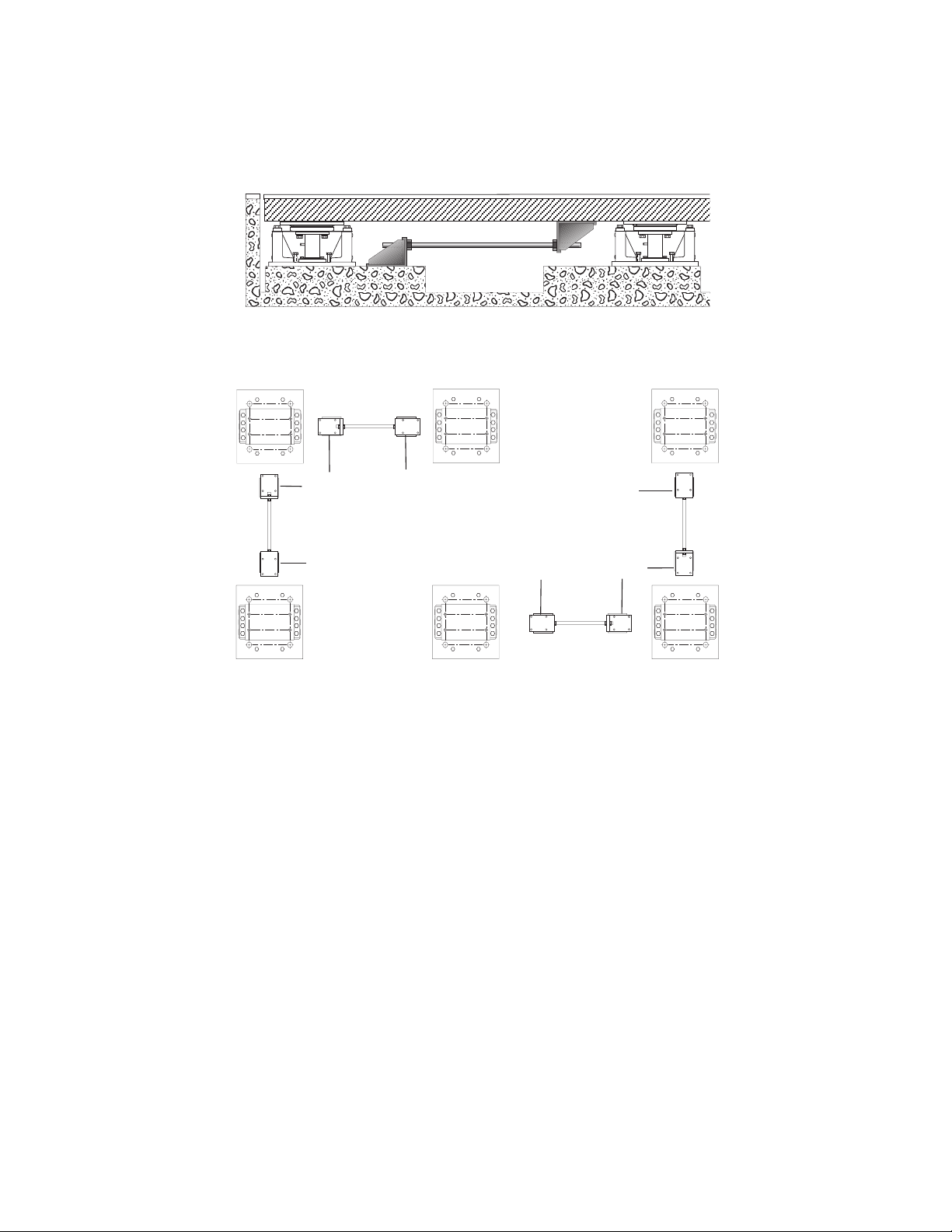
Check rod between foundation and scale deck I-beam (front view)
Mount to
foundation
Mount to
I-Beam
Mount to
I-Beam
50K—1" diameter checking rod
100K—1-3/4" diameter checking rod
200K—2" diameter checking rod
Mount to
I-Beam
Mount to
I-Beam
Mount to
foundation
Multiple mount check rod placement (top view)
3.3.3 Re-leveling, Securing, Grouting, and Grounding the Base
1. Re-level the mount using leveling lugs. You might have to move the base
plate around or adjust the leveling bolts to reach the proper horizontal
alignment of the base plate and retaining plate. A perfectly level system
will minimize side loads and bending moments.
2. Remove the blocking for the particular mount so that the platform and
scale deck I-beam are resting solely on the mount.
3. Install all the other mounts in the system in the above manner before
bolting and grouting the base plates. After all the mounts are in place,
remove all other blocking and remove the platform wedges making sure
it is still centered in the pit. If not, then re-wedge and adjust the mounts as
necessary. When you are sure that the platform is at the final height and has
the proper clearance, then proceed to anchor the base plates.
8
Page 11

4. Drill holes in the concrete foundation maintaining the height of the
leveling bolts. Bolt the base to the foundation (see Appendix for base
mounting hole dimensions). Use concrete stud anchors or equivalent.
Make a final check to see that everything is in place and level.
5. Pour grout under the base plates. Use good quality non-shrinking grout.
Stir under the base plate to remove any air pockets. After the grout has
hardened, back the four leveling bolts out of the grout.
6. Install a grounding strap around the load cell.
3.3.4 Installing the Load Cell
When placing parts on the load cell, be careful not to
Caution
1. Remove load from mount. Jack up I-beam and take load off dummy cell.
2. Place the shims on the load cell mounting plate and the load cell on top of
the shims. Then screw the load cell screw into load cell through the bottom
of the load cell mounting plate.
3. Slide the load cell assembly into the mount and screw the load cell
mounting plate bolts and lockwashers into the base plate.
4. Torque the load cell mounting plate bolts to spec (see torque value table,
page 4).
drop or slam parts on the load cell. This sudden force
could shock your load cell making the scale inoperable.
3.3.5 Removing the Load Cell
1. Power down the indicator.
2. Remove the junction box cover, disconnect the load cell wires from the
junction box circuit board, and pull the load cell cable out of the junction
box.
3. Remove load from mount. Jack up I-beam and take load off dummy cell.
4. Remove the four load cell mounting plate bolts and lockwashers. Slide the
load cell assembly out of the mount.
5. Loosen the load cell screw under the load cell mounting plate and remove
the load cell.
9
Page 12
4. Load Cell Wiring
a
a
a
a
a
a
a
aa
a
aa
aaa
a
a
a
a
a
a
a
aa
a
a
aa
a
a
a
a
a
aa
aa
a
a
a
a
aa
a
a
a
a
a
a
a
a
a
a
a
a
a
a
a
aa
a
a
a
a
1. Route the load cell cables so they will not be damaged or cut. Cable should
not be routed near heat sources greater than 150° F. Do not shorten any load
cell cable. The load cell is temperature compensated with the supplied
length of cable. Cutting the cable will affect temperature compensation.
Coil excess cable and protect it so it will not be mechanically damaged or
be sitting in water.
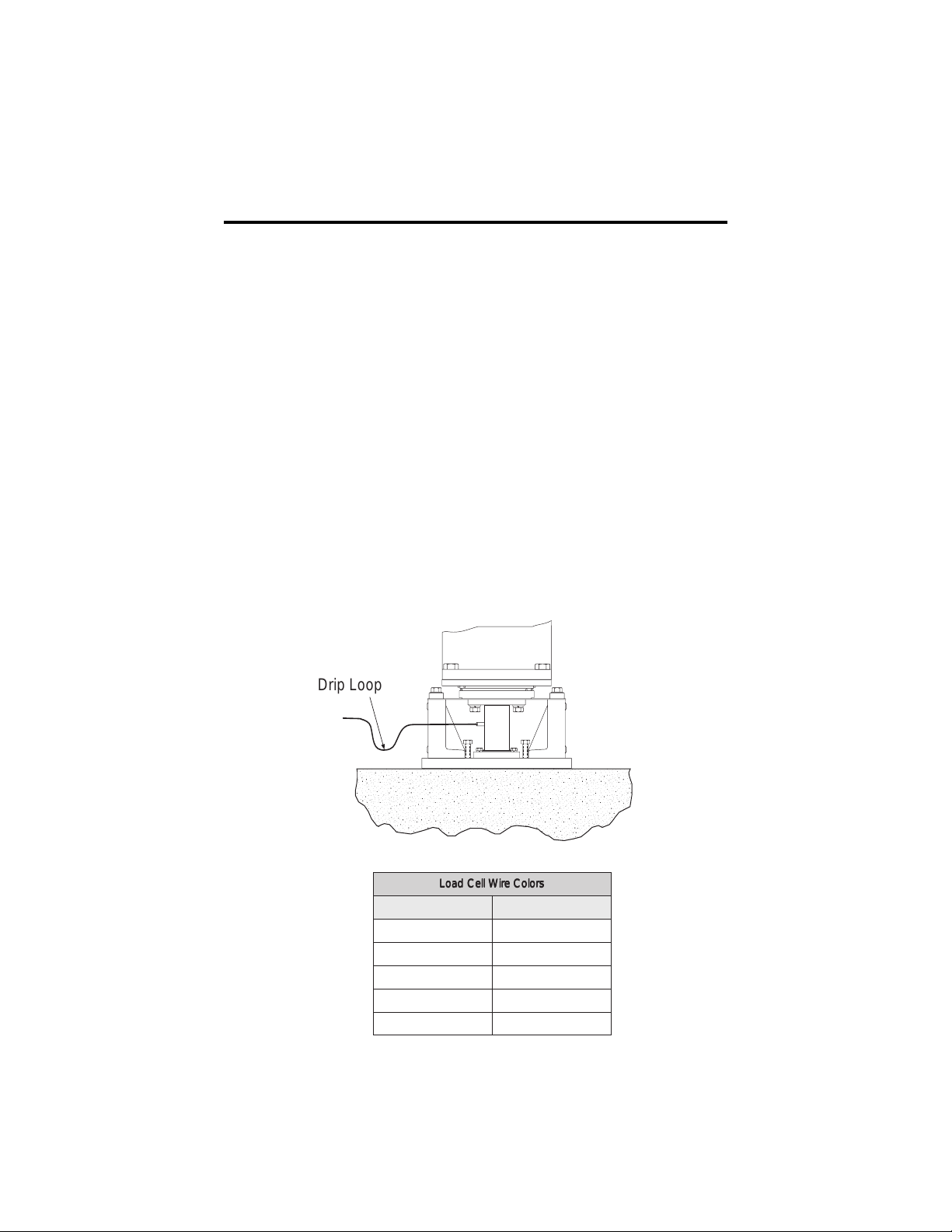
2. Provide a drip loop in all cables so that water or other liquids will not run
directly down the cables onto either the load cells or the junction box.
Attach load cell cable to the dead structure, not the vessel.
3. If conduit protection is necessary against mechanical or rodent damage to
the load cell cables, use flexible conduit and conduit adapters at the load
cells.
4. Connect cables for the load cells to the summing board in the junction box
according to the guide shown below and the labels on the terminal strips
of the junction box. To verify the wiring scheme, see the certification
shipped with the load cell.
5. If the wiring run from the junction box to the indicator is longer than 25
feet, use positive and negative remote sense lines for better performance.
Drip Loop
sroloCeriWlleCdaoLsroloCeriWlleCdaoL
sroloCeriWlleCdaoLsroloCeriWlleCdaoL
sroloCeriWlleCdaoL
roloCeriW noitcnuF
neerGCXE+
kcalBCXE–
etihWGIS+
deRGIS–
egnarODLEIHS
10
Page 13

5. Junction Box Connections, Adjustments & Calibration
• Refer to Junction Box manual for trimming details.
• Refer to indicator manual or the “Technical Information” section in Rice Lake
Weighing Systems’ Load Cell Product Selection Guide for system calibration
details.
6. Troubleshooting
If the system powers up and gives some type of stable digital readout that varies with
the load on the system, any system problems are probably caused by factors other
than the load cells. All too often, the load cells are blamed for a malfunctioning
system, but 90% of the time, the problem lies elsewhere. Look for mechanical
causes for your problem first.
If the system can be calibrated but doesn’t return to zero, loses calibration, or
demonstrates non-linearity or non-repeatability, see the following chart for possible
causes and refer to the following list of checks.
motpmySmotpmyS
motpmySmotpmyS esuaCelbissoPesuaCelbissoP
motpmyS
orezotnruteroN noitarbilacmetsystsolevahyam;sllecdaolrednuroslaesnisirbedrognidniblacinahceM
ytiraenil-noN daoledisrognidnibgnisuacdaolrednunoitcelfedronoisnapxelamrehT
ytilibataeper-noN
noitarbilactsoL gnidniblacinahcem;melborperutsiom;bmulprolevelfotuO
tuodaergnitfirD gnidniblacinahcem;llecdaolro,selbac,xobnoitcnujnierutsioM
gnidniblacinahcem
esuaCelbissoPesuaCelbissoP
esuaCelbissoP
;egamadkcohsrodaolrevollecdaol,erutsiomybdesuacgnitfird;tnuomllecdaolesooL
1. Check load cell mount for debris restricting load cell movement or debris
between scale and structure. Check any overload stops for proper clearance.
2. Check that tank/vessel and mounts are plumb, level, and square at critical areas.
3. Check all piping and conduit for connections which restrict vessel movement.
4. If check rods are used, loosen all connections to finger tight only for testing.
5. Check load cell cables for physical or water damage.
6. Check all electrical connections, especially in the junction box.
If the problem still is not found:
7. Check possible indicator malfunction by using a load cell simulator to input a
known good signal into the indicator.
8. Disconnect each load cell’s signal leads at the junction box and check
individual load cell outputs with a multimeter. Then check input/output
impedances for comparison with load cell manufacturer’s specifications.
If after all these checks the problem still cannot be isolated, reconnect all but one
load cell. Replace the load cell with a load cell simulator. Alternate so that each load
cell is individually disconnected and replaced with a simulator. If there is a problem
with a particular load cell, the symptom should disappear when that load cell is
disconnected and replaced with the simulator.
11
7
Page 14
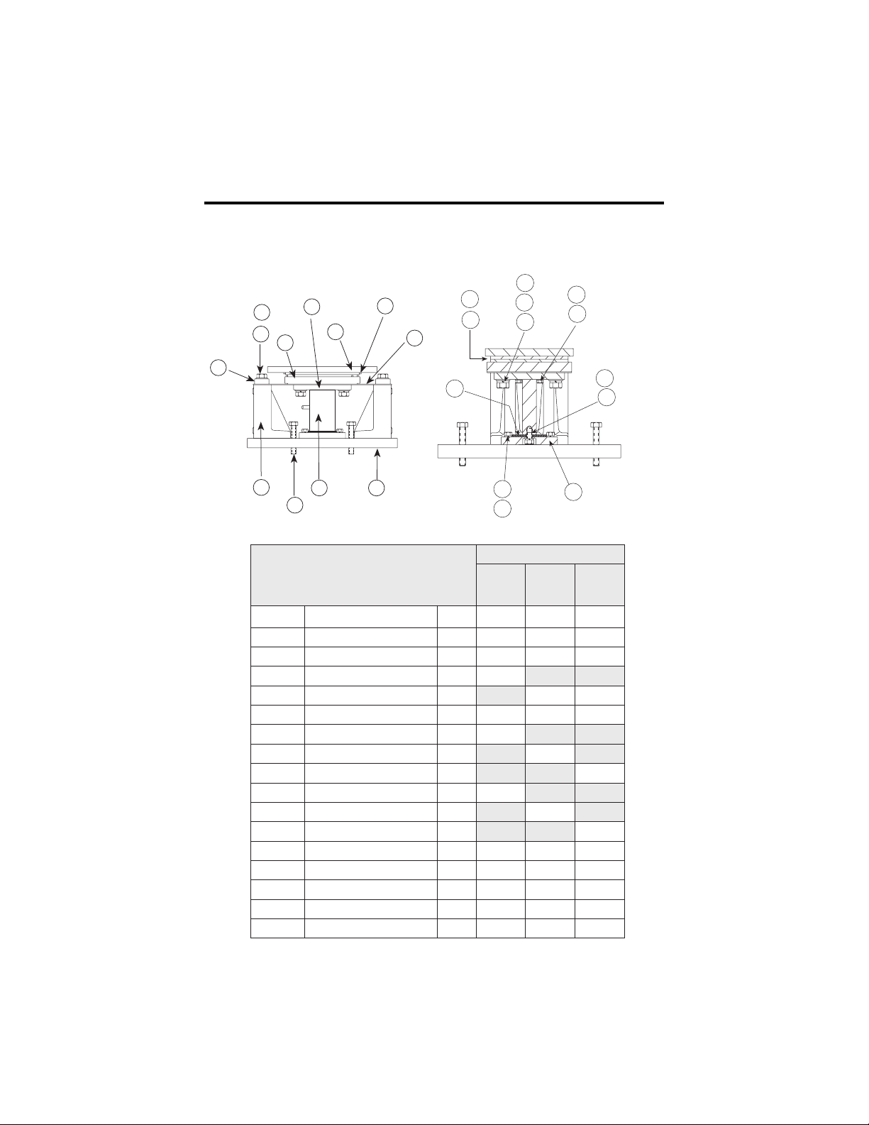
7. Replacement Parts
When replacing a compression canister type load cell, replace the load cell top
mounting plate also. After years of use the bearing plate gets worn where the load
cell button contacts the plate. If not replaced, it could cause weighing inaccuracies.
5
6
10
7
4
2
3
0)tinuelohw(tnuoMangaM479714271232712
1etalPesaB1384819332236122
2dnatS2884811432256122
3DHTlluf"5xCNU9-"8/7,tloB411201
3DHTlluf"3x11-"8/5,tloB41822218222
4kcolBrohcnA2984812432255122
5"00.1nialP,rehsaW2138151
5"4/3nialP,rehsaW697151
5"8/5nialP,rehsaW4 77151
65drGDHxeH"21x8-"00.1,tloB849741
65drGDHxeH"9x01-"4/3,tloB634322
65drGDHxeH"6x11-"8/5,tloB4 55222
7etalPmottoB1394814432225122
8etalPgniniateR1694815432285122
9lleCdaoLymmuD1584816432235122
01etalPgnitnuoMpoT1684817432216122
11etalPeruxelF1194819432265122
24
8
9
11
1
23
.ytQnoitpircseDrebmuN
13
12
21
22
A
15
14
5
17
16
18
19
20
srebmuNtraP
B
bl000,002
yticapac
C
bl000,001
yticapac
bl000,05
yticapac
12
Page 15

srebmuNtraP
A
.ytQnoitpircseDrebmuN
21)pot(daPakeerbaF1594818432295122
31)mottob(daPakeerbaF1494810532206122
41"00.1,rehsawkcoL458151
41"4/3,rehsaW497151
41"8/5,rehsaW4 77151
51"05.2x8-"00.1paC,wercS
5drGDHxeH
51"57.1x01-"4/3paC,wercS
5drGDHxeH
51"52.1x11-"8/5paC,wercS
5drGDHxeH
61rehsawtalf"2/1437151
715drGDHxeH"2x31-"2/1469022
81"4/3rehsawkcoL11815118151
81"2/1rehsawkcoL1 76151
91xeH1x61-"4/3paC,wercS
5drGDH
91"8/5x02-"2/1paC,wercS
5drGDHxeH
02etalPgnitnuoMlleCdaoL1484812532245122
12"8/5,rehsawkcoL43532235322
12"2/1,rehsawkcoL2 76151
22DHxeH"57.1x11-"8/5tloB
2drG
22xeH"2x11-"8/5paC,wercS
8drGDH
22"52.1x31-"2/1paC,wercS
8drGDHxeH
32mihS989481
32mihS489481
32mihS6 75122
42niPnoisneT"4/3x"4/18362513625136251
eeS-slleCdaoL ediuGnoitceleStcudorPlleCdaoL 43503NP-
439741
415322
4 65222
16905169051
1 75222
417741
419051
2 95051
B
bl000,002
yticapac
C
bl000,001
yticapac
bl000,05
yticapac
13
5
Page 16

8. Appendix—Mount Dimensions
L
L1
W5
C DIA. THRU. (4)
T (4)
W3
W4
L4
H
L3
L2
W2
W
W1
sehcnI-snoisnemiD
detaR
yticapaC
CL1L2L3L4LH
bl000,0552.100.3157.152.1105.873.193.7
bl000,00105.100.0205.200.8105.5152.192.11
bl000,00200.200.6200.500.9100.6105.101.41
sehcnI-snoisnemiD
detaR
yticapaC
T W 1W 2W 3W 4W 5W
bl000,05CNU01-4/300.2157.105.800.805.457.1
bl000,001CNU9-8/700.7105.200.2100.905.557.1
bl000,002CNU8-100.6200.500.6105.2105.505.3
14
Page 17

MagnaMount Limited Warranty
Rice Lake Weighing Systems (RLWS) warrants that all RLWS brand load cells
properly installed by a Distributor or Original Equipment Manufacturer (OEM) will
operate per written specifications. All load cell products are warranted against
defects in materials and workmanship for two (2) years. Products marked as
“waterproof” are warranted against defects in materials and workmanship relating
to moisture ingress.
RLWS warrants that the equipment sold hereunder will conform to the current
written specifications authorized by RLWS. RLWS warrants the equipment against
faulty workmanship and defective materials. If any equipment fails to conform to
these warranties, RLWS will, at its option, repair or replace such goods returned
within the warranty period subject to the following conditions:
• Upon discovery by Buyer of such non-conformity, RLWS will be given
prompt written notice with a detailed explanation of the alleged deficiencies.
• Examination of such equipment by RLWS confirms that the non-conformity
actually exists, and was not caused by accident, misuse, neglect, alteration,
improper installation, improper repair or improper testing; RLWS shall be the
sole judge of all alleged non-conformities.
• Such equipment has not been modified, altered, or changed by any person
other than RLWS or its duly authorized repair agents.
• RLWS will have a reasonable time to repair or replace the defective equip-
ment. Buyer is responsible for shipping charges both ways.
• In no event will RLWS be responsible for travel time or on-location repairs,
including assembly or disassembly of equipment, nor will RLWS be liable for
the cost of any repairs made by others.
THESE WARRANTIES EXCLUDE ALL OTHER WARRANTIES, EXPRESSED
OR IMPLIED, INCLUDING WITHOUT LIMITATION WARRANTIES OF
MERCHANTABILITY OR FITNESS FOR A PARTICULAR PURPOSE. NEITHER RLWS NOR DISTRIBUTOR WILL, IN ANY EVENT, BE LIABLE FOR
INCIDENTAL OR CONSEQUENTIAL DAMAGES.
RLWS AND BUYER AGREE THAT RLWS’S SOLE AND EXCLUSIVE LIABILITY HEREUNDER IS LIMITED TO REPAIR OR REPLACEMENT OF
SUCH GOODS. IN ACCEPTING THIS WARRANTY, THE BUYER WAIVES
ANY AND ALL OTHER CLAIMS TO WARRANTY.
BE OTHER THAN RLWS, THE BUYER AGREES TO LOOK ONLY TO THE
SELLER FOR WARRANTY CLAIMS.
SHOULD THE SELLER
No terms, conditions, understanding, or agreements purporting to modify the terms
of this warranty shall have any legal effect unless made in writing and signed by a
corporate officer of RLWS and the Buyer.
© 1999 Rice Lake Weighing Systems, Inc. Rice Lake, WI USA. All Rights Reserved.
RICE LAKE WEIGHING SYSTEMS • 230 WEST COLEMAN STREET •
RICE LAKE, WISCONSIN 54868 • USA
3
 Loading...