

Page 1
920i® Weighcenter
Remove all screws
Note
Drill Hole
Power Switch
Contrast Control Potentiometer Installation
PN 160965
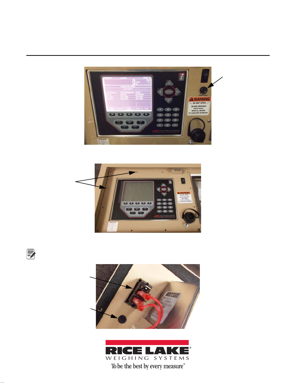
The following instructions are for the installation of the Contrast Control Potentiometer into the 920i Weighcenter.
Figure 1. Contrast Control Potentiometer Installed
1. Remove the screws to remove the front bezel from the weighcenter frame.
2. Drill a 25/64” hole in the front bezel at 3/4” under the power switch.
March 24, 2014 161635 Rev A
Figure 2. Remove Front Bezel
A 3/8” bit will work if you ream the hole with the bit.
Figure 3. Drill Hole
Page 2
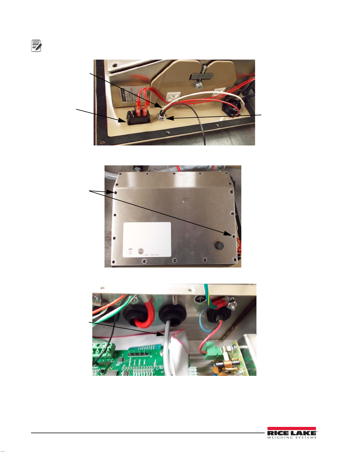
3. Insert the potentiometer into the hole and tighten down with 1/2” wrench.
Note
Power Switch
Contrast Control
Potentiometer
White wire towards
power switch
Remove all screws
Route Cable
Ensure the white wire is oriented towards power switch as shown.
Figure 4. Install Contrast Control Potentiometer
4. To remove back plate, remove the screws securing the it to the indicator.
5. Route the 8-pin connector cable through cord grip.
Figure 5. Remove Indicator Back Plate
Figure 6. Route Wiring Through Cord Grip
2 Contrast Control Potentiometer Installation
Page 3

6. Locate J14, J16, J17 on the CPU board and remove the black jumpers.
Remove Jumpers
Connector - Red
wire on pin1 of J14
Red to red
White to white
Black to black
Figure 7. Locate and Remove Jumpers
7. Install the 8-pin connector as shown in Figure 8 making sure red wire is on Pin 1 of J14.
8. Using the splice taps, connect the wires from the potentiometer to the wires from the connector, see Figure 9.
•Red to red
• White to white
• Black to black
Figure 8. Eight Pin Connector
Figure 9. Connect Wires
Contrast Control Potentiometer Installation 3
Page 4

9. Gather wires and wire tie the cable to the anchors.
Wire ties and
anchors
Rotate knob to
adjust contrast.
230 W. Coleman St. • Rice Lake, WI 54868 • USA
U.S. 800-472-6703 • Canada/Mexico 800-321-6703 • International 715-234-9171 • Europe +31 (0) 88 2349171
www.ricelake.com www.ricelake.mx www.ricelake.eu www.ricelake.co.in m.ricelake.com
Figure 10. Secure Wires
10. Tighten cord grip and reassemble the unit.
11. Power unit up and verify the contrast potentiometer functions.
Figure 11. Contrast Control Potentiometer Installed
Rice Lake Weighing Systems is an ISO 9001 registered company.
© Rice Lake Weighing Systems 03/2014 PN 161635
 Loading...