

Page 1
EL-304A
Four-Channel Signal T rim Junction Box
Installation Manual
16937
Page 2
Introduction
The EL-304A Junction Box can accommodate up to four load cells. Additional
load cells may be connected to the EL-304A Junction Box by wiring additional
junction boxes to the EXPANSION terminal on the EL-304A. Load cell output can
be trimmed with potentiometers either individually or paired in sections.
When correctly installed, the NEMA 4X fiberglass-reinforced polyester enclosure
will withstand 40 psi water pressure. It is not, however, designed for highpressure washdown applications, exposure to steam, or exposure to hightemperature liquids.
CHANGING CABLE LENGTH
Locate the junction box so load
cell cable length need not be
changed. Load cell output is
temperature-compensated for the
supplied cable length. Altering
that length will alter the cell’s
signal output.
Mounting the Junction Box Enclosure
Mount the enclosure in a location convenient for servicing and away from
standing water. Try to mount the enclosure in a location that will not require
extending the load cell cables.
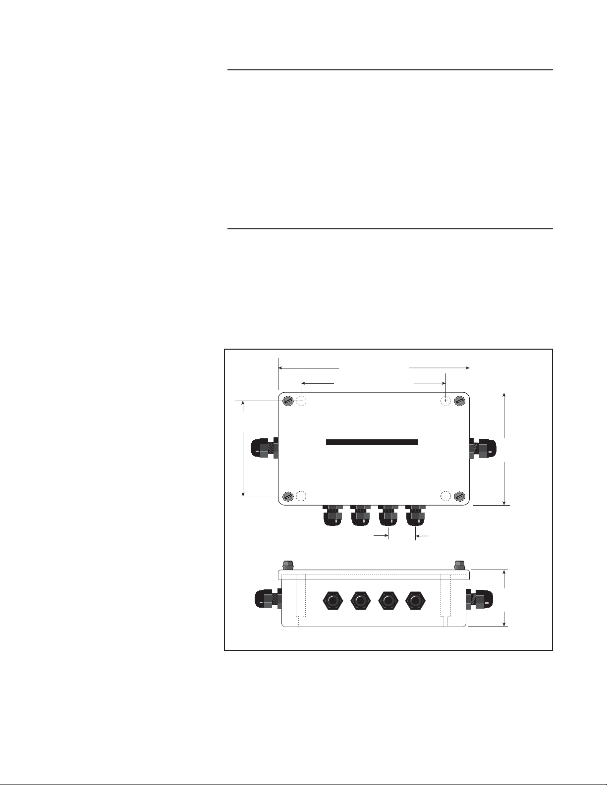
Depending on the mounting surface, the enclosure is attached using the four panhead screws provided, bolts, or other suitable masonry fasteners. Figure 1 below
shows dimensions for mounting the enclosure.
9.88" (251mm)
7.625" (193.6mm)
5.625"
(142.8mm)
RICE LAKE WEIGHING SYSTEMS
6.62"
(168.1mm)
FIGURE 1: EL-304A ENCLOSURE DIMENSIONS
© 1996 Rice Lake Weighing Systems, Inc., Rice Lake, WI USA. All Rights Reserved
Rice Lake Weighing Systems, Inc., 230 West Coleman Street, Rice Lake, WI 54868
Main Office (715) 234-9171 Service (715) 234-2003 FAX (715) 234-6967
1
1.38" (35.1mm)
3.25"
(82.6mm)
12/96
Page 3

Wiring
WIRING PATTERN
See back cover of Rice Lake
Weighing Systems Load Cell
Product Selection Guide for
wiring color codes.
1 2 3 4
DIP switches 3 & 4 must
be ON to enable trimming.
OFF
The terminal strips are labeled “Cell 1” through “Cell 4” and are used to connect
the individual load cells. Determine the number of load cells to be connected to
the junction box. The EL-304A has been designed to connect and trim four load
cells. However, it is possible to use this box with other combinations. On a track
scale or other system where load cells may be connected together in section
“pairs”, even numbers of cells (four or eight) may be used with the EL-304A. This
is done by paralleling the excitation and signal leads of a load cell pair, and
connecting them to the same input on the J-Box. However, it is recommended
practice when using more than four load cells to “daisy-chain” EL-304A J-Boxes
together using the expansion connectors.
After determining the wiring pattern, route the load cell cables through the nylon
cord grip assemblies. Leave the grips loose until final closure. Before connecting
load cell cables to the terminals, check that all wire ends have been properly
stripped and tinned. Connect the load cell and indicator cables to the appropriate
connectors. DIP switches 3 and 4 must be ON for any cells which you will be
trimming. If using less than four load cells, remove any unused channels from the
circuit by turning dip switches 3 and 4 to OFF on those channels.
SHLD
–SIG
+SIG
+EXC
–EXC
SHLD
–SIG
+SIG
+EXC
–EXC
CABLE DRIP LOOPS
If cables will be exposed to water
or other liquids, bend a short
downward loop in all cables near
the cord grips so any fluids
draining down the cables will drip
off before reaching the junction
box.
SENSE LEADS
Use sense leads to correct small
errors which can cause inaccurate readings and drifting
problems, especially if the
indicator is located far from the
junction box.
EXPANSION
SHLD
+SIG
–SIG
+SEN
+EXC
–SEN
–EXC
EL 304A
REVISION 1
1-90
SECTION #1
CELL #2 CELL #3
1 2 3 4
OFF
SECTION #2
RICE LAKE WEIGHING SYSTEMS
TRIM
SHLD
–SIG
OFF
ON
1 2 3 4
OFF
CELL #1
+SIG
+EXC
–EXC
TRIM
SHLD
–SIG
1 2 3 4
OFF
OFF
ON
1 2 3 4
OFF
CELL #4
+SIG
+EXC
INDICATOR
SHLD
+SIG
–SIG
+SEN
+EXC
–SEN
–EXC
EL304A COMPONENTS REV. 1.0 (1-90)
–EXC
FIGURE 2: EL-304A MAIN BOARD
The INDICATOR terminal strip is used to connect the main cable to the indicator.
Determine the indicator’s load cell input connections from the operating manual.
Run a cable from the indicator to the junction box through the larger cord grip and
make the connections on the INDICATOR terminal.
2
Page 4

Whenever a large amount of trim
seems necessary to equalize
output (more than 7% of normal
output), check for other possible
problems. Always strive for the
least amount of trim.
Trimming Procedure
The EL-304A J-Box is a signal trimming device. Each cell can be set for coarse,
medium, or fine trim with its own 4-pole dip switch. Switches 1 and 2 work in various
combinations to alter the sensitivity of the trimming potentiometers as shown in the
table below. Switches 3 and 4 must be ON for each active cell to enable trimming.
Approximate Trim Ranges - EL-304A Summing Board
tnemtsujdA
1hctiwS 2hctiwS
FFOFFOenoNenoNenoN
FFONOeniF%8.6–%53.%8.21–%7.
NOFFOmuideM%5.21–%53.%3.22–%7.
NONOesraoC%6.71–%53.%9.92–%7.
egnaR
053 Ω slleC 007 Ω slleC
NOTE: On older models of the
EL-304A Junction Box, the
Section Trim pots work in the
opposite direction as the
Individual Cell Trim pots.
To decrease resistance for
maximum signal on these
units, turn Individual pots
counterclockwise and Section
pots clockwise.
Caution
!
When loading the corners with
test weights, do not exceed the
concentrated load capacity
(CLC) specified by the scale
manufacturer.
For example, to enable trimming using the fine adjustment range, set DIP switches
2, 3 and 4 on active channels to ON, and switch 1 to OFF.
1. Turn the four individual cell potentiometers fully counterclockwise to give
maximum signal output from each cell.
To trim cells individually, be sure the Section Trim jumpers
are in the OFF position as shown at right.
2. To trim cells in pairs, set the Section Trim jumpers to the
ON position. If section trimming is chosen, turn the two
section potentiometers fully counterclockwise so both
sections are at maximum signal output.
3. Remove all weight from the scale and zero the indicator. Place calibrated test
weights over each load cell or section in turn. The amount of test weights to
be used will depend on the scale configuration; for specific recommendations,
refer to
Technology (NIST). For a four-cell platform, we recommend using 25% of
scale capacity.
4. Record the value displayed on the indicator after the test weight is placed in
turn on each corner, directly over the load cell, or over each section. Allow the
scale to return to zero each time to check for friction or other mechanical
problems. Select the load cell or section that has the lowest value as your
reference point. This cell or section will not be trimmed.
Handbook 44
, published by the National Institute of Standards and
SECTION #1
OFF
TRIM
ON
Caution
!
To prevent water and other
contaminants from entering the
J-Box, fill any unused cable grips
with post screw plugs (part
number 19538). One plug is
provided.
5. Place the same test load over each cell or section in turn. Using the
corresponding potentiometer, trim each cell or section down to equal the
reference point. As corner corrections are somewhat interactive, check all
cells or sections again for repeatability. If necessary, repeat steps 4 and 5.
6. Tighten the cord grip assemblies with a wrench. To be watertight, each cord
grip must be tightened so the rubber sleeve begins to protrude from the hub.
7. Unused hubs must be plugged to prevent moisture entry. See the
Replacement Parts and Components
8. Insert the enclosed desiccant bag and replace the cover, tightening the cover
screws in an alternating pattern to be certain the gasket is compressed equally
in all locations. If the enclosure is located in a damp or wet area, change the
desiccant (part number 16038) every four to six months.
3
catalog to order extra hole plugs.
Electronic
 Loading...