

Page 1
EL-204
Installation Instructions
For PN 73428
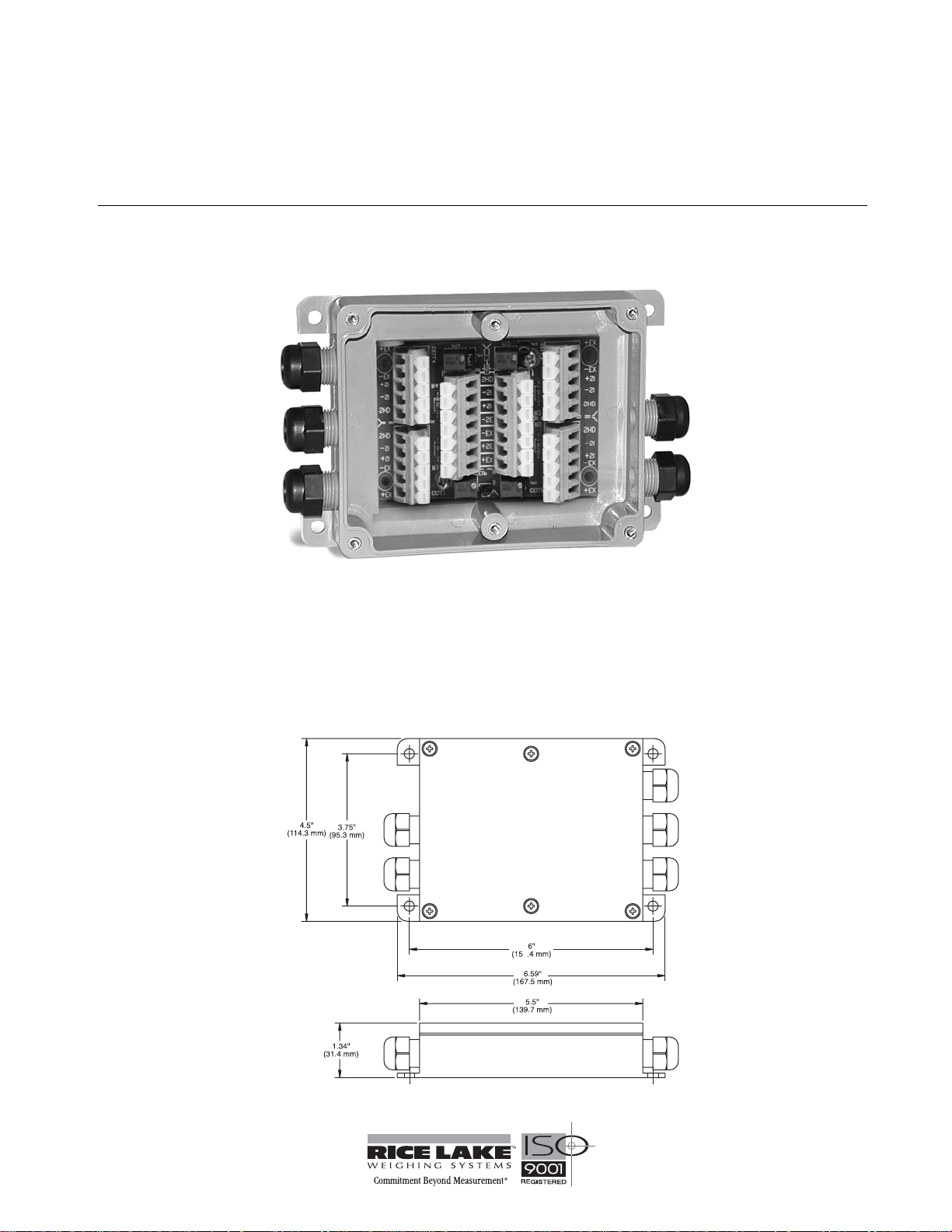
The EL-204 is a signal trim junction box that can accommodate up to four load cells.
It has an ABS molded enclosure and molded-in nylon compression cable fittings that provide an extra waterproof
Figure 1 illustrates the EL-204 junction box with its six-screw attachment lid removed.
seal.
Figure 1. EL-204 Junction Box
EL-204 Junction Box Mounting Procedure
Mount the junction box in a location convenien t for servicing and away from standing water. Try to mount the
enclosure in a location so that the load cell cables need not be cut, nor length added. Load cell output is
temperature compensated for the supplied cable length. Altering that length can change the cell’s signal output.
Depending on the mounting surface, the EL-204 enclosure can be attached using two pan-head screws, bolts or
other suitable fasteners. Figure 2, below, shows the dimensions for mounting the enclosure.
Figure 2. EL-204 Enclosure Dimensions
January 2007 98088
Page 2
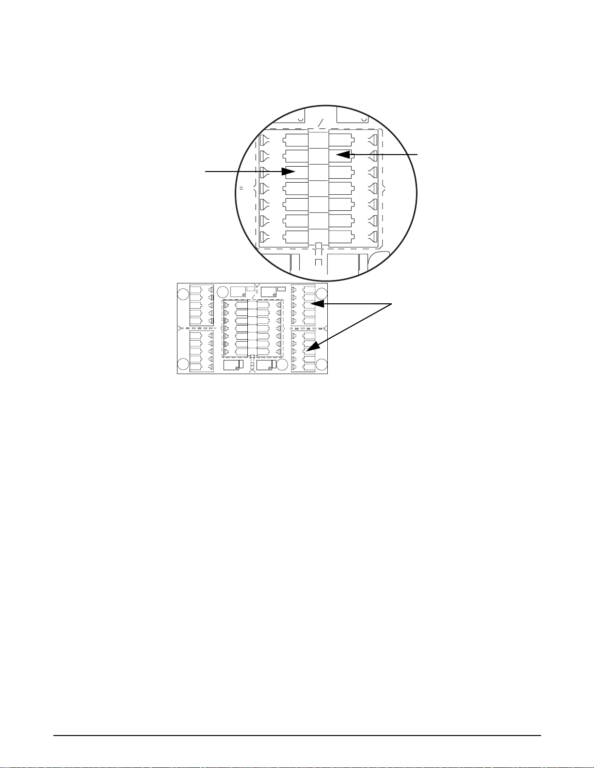
Wiring the Junction Box
The EL-204 junction box has been designed to connect and trim up to four load cells pe r board. For applications
that use more than four load cells, use the expansion port on the main board to connect an additional junction box.
EXP
IND
If the expansion port is not
used to connect to another
junction box, indicator
connections can be made on
either terminal block.
1
+EX
+SE
Wires to the indicator
-EX
-SE
+SI
-SI
1
SHD
+EX
-EX
+SI
-SI
SHD
SHD
-SI
+SI
-EX
+EX
CELL1
1
1
M
CELL4
JP1
PT1
EXP
IND
+EX
+SE
-EX
-SE
+SI
-SI
1
SHD
JP4
PT4 PT3
CELL2
JP2
PT2
1
JP3
+EX
-EX
+SI
-SI
1
SHD
SHD
-SI
+SI
-EX
S2C
1
CELL3
+EX
Wires to load cells (both sides)
Figure 3. Expansion Board Wiring Location
After determining the wiring pattern, route the load cell cables through the cord grip assemblies and leave the grips
loose until final closure. Before connecting the load cell wires to the terminals, strip the wire insulation back 1/4"
to expose the wire. The spring loaded terminals will accommodate 12 to 28 gauge wire. To connect the load cell
wires to the appropriate connectors, push in the quick-connect level with a small screwdriver. While holding the
lever, insert the appropriate wire into the exposed wire open ing. Release the screwdriver to allow the spring-loaded
gate to close and lock the wire into place.
The indicator terminal strip, which is located on the expansion port is used to connect the main home run cable to
the indicator. Determine the indicator’s load cell input connections from the indicator operating manual. Run a
cable from the indicator into the junction box through the larger cord grip and connect to the indicator terminal
strip.
Trimming Procedure
Trimming is a process of equalizing the output from multiple individual load cells. If needed, load cell output can
be individually trimmed with potentiometers.
Whenever a substantial amount of trim (more than 5% of normal output), seems necessary to equalize output check
for other possible problems. The best trim is always the least amount of time. When all errors except cell mismatch
and cable extensions or reductions have been corrected, continue with the trimming.
Use the following steps to properly trim the EL-204 junction box.
1. Determine the number of load cells needed.
2. Make sure the jumpers are in place to enable trimming of the desired cells corresponding to each load cell
in use. If you have any unused cells, remove the jumpers corresponding to those cells. See
location of jumpers JP1, JP2, JP3, and JP4.
3. Set all potentiometers fully clockwise to give maximum signal output from each cell. (See the location of
the potentiometers in
Figure 4.)
Figure 4 for the
2 EL-204 Installation Instructions
Page 3

SHD
SHD
+SI
-EX
+EX
-SI
-SI
+EX
-EX
+SI
Jumper Locations
JP1 and JP 2
Potentiometers
Shaded
1
1
CELL1
S
I
G
N
A
L
T
R
I
M
CELL4
PT4
PT1
EXP
JP4
JP1
+EX
+SE
-EX
-SE
+SI
-SI
SHD
PT2
IND
PT3
CELL2
JP2
S
I
G
N
A
L
T
R
I
M
CELL3
S2C
JP3
+EX
-EX
+SI
-SI
1
SHD
SHD
-SI
+SI
-EX
1
+EX
Jumper Locations
JP3 and JP 4
Potentiometers
Shaded
Figure 4. Signal Main Board
4. Zero the indicator and place calibrated test weights over each load cell in turn. The amount of test weights
to be used will depend on the scale configuration; for specific recommendations, refer to Handbook 44
Field Manual, published by the Institute for Weights and Measures. For a four-cell platform, it’s
recommended using 25% of scale capacity.
5. Record the value displayed on the indicator after the test weight is placed in turn on each corner (directly
over the load cell), without allowing the weight to overhang the sides. Allow the scale to return to zero
each time to check for friction or other mechanical problems. Select the load cell which has the lowest
value as your reference point. This cell will not be trimmed.
6. Replace the same test load over each cell in turn. Using the corresponding potentiometer, trim each cell
down to equal the reference load cell. As corner corrections are somewhat interactive, check all cells again
for repeatability. If necessary, repeat steps four and five.
7. Pull excess cable out of the enclosure and tighten the cord grip assemblies with a wrench. To be watertight,
each cord grip must be tightened so the rubber sleeve begins to protrude from the hub.
8. Unused hubs must be properly plugged to prevent moisture entry. See the Electronic Replacement Parts
and Components catalog to order extra hole plugs.
9. Remove the desiccant from the plastic bag and insert the desiccant bag into the junction box before
closing. Inspect the desiccant during normal service and change the desiccant as needed.
10. Replace the cover and tighten the cover screws in an alternating pattern to 15 in/lb to be certain the
junction box cover is compressed equally in all locations.
3
Page 4

EL-204 Limited Warranty
Rice Lake Weighing Systems (RLWS) warrants that all RLWS equipment and systems properly installed by a
Distributor or Original Equipment Manufacturer (OEM) will operate per written specifications as confirmed by the
Distributor/OEM and accepted by RLWS. All systems and components are warranted against defects in materials
and workmanship for one year.
RLWS warrants that the equipment sold hereunder will conform to the current written specifications authorized by
RLWS. RLWS warrants the equipment against faulty workmanship and defective materials. If any equipment fails
to conform to these warranties, RLWS will, at its option, repair or replace such goods returned within the warranty
period subject to the following conditions:
• Upon discovery by Buyer of such nonconformity, RLWS will be given prompt written notice with a
detailed explanation of the alleged deficiencies.
• Individual electronic components returned to RLWS for warranty purposes must be packaged to prevent
electrostatic discharge (ESD) damage in shipment. Packaging requirements are listed in a publication,
Protecting Your Components From Static Damage in Shipment, available from RLWS Equipment Return
Department.
• Examination of such equipment by RLWS confirms that the nonconformity actually exists, and was not
caused by accident, misuse, neglect, alteration, improper installation, improper repair or improper testing;
RLWS shall be the sole judge of all alleged non-conformities.
• Such equipment has not been modified, altered, or changed by any person other than RLWS or its duly
authorized repair agents.
• RLWS will have a reasonable time to repair or replace the defective equipment. Buyer is responsible for
shipping charges both ways.
• •In no event will RLWS be responsible for travel time or on-location repairs, including assembly or
disassembly of equipment, nor will RLWS be liable for the cost of any repairs made by others.
THESE WARRANTIES EXCLUDE ALL OTHER WARRANTIES, EXPRESSED OR IMPLIED, INCLUDING WITHOUT LIMITATION
WARRANTIES OF MERCHANTABILITY OR FITNESS FOR A PARTICULAR PURPOSE. NEITHER RLWS NOR DISTRIBUTOR
WILL, IN ANY EVENT, BE LIABLE FOR INCIDENTAL OR CONSEQUENTIAL DAMAGES.
RLWS AND BUYER AGREE THAT RLWS’S SOLE AND EXCLUSIVE LIABILITY HEREUNDER IS LIMITED TO REPAIR OR
REPLACEMENT OF SUCH GOODS. IN ACCEPTING THIS WARRANTY, THE BUYER WAIVES ANY AND ALL OTHER CLAIMS
TO WARRANTY.
SHOULD THE SELLER BE OTHER THAN RLWS, THE BUYER AGREES TO LOOK ONLY TO THE SELLER FOR WARRANTY
CLAIMS.
NO TERMS, CONDITIONS, UNDERSTANDING, OR AGREEMENTS PURPORTING TO MODIFY THE TERMS OF THIS
WARRANTY SHALL HAVE ANY LEGAL EFFECT UNLESS MADE IN WRITING AND SIGNED BY A CORPORATE OFFICER OF
RLWS
AND THE BUYER.
© 2007 Rice Lake Weighing Systems, Inc. Rice Lake, WI USA. All Rights Reserved.
RICE LAKE WEIGHING SYSTEMS • 230 WEST COLEMAN STREET • RICE LAKE, WISCONSIN 54868 • USA
4 EL-204 Installation Instructions
 Loading...