

Page 1
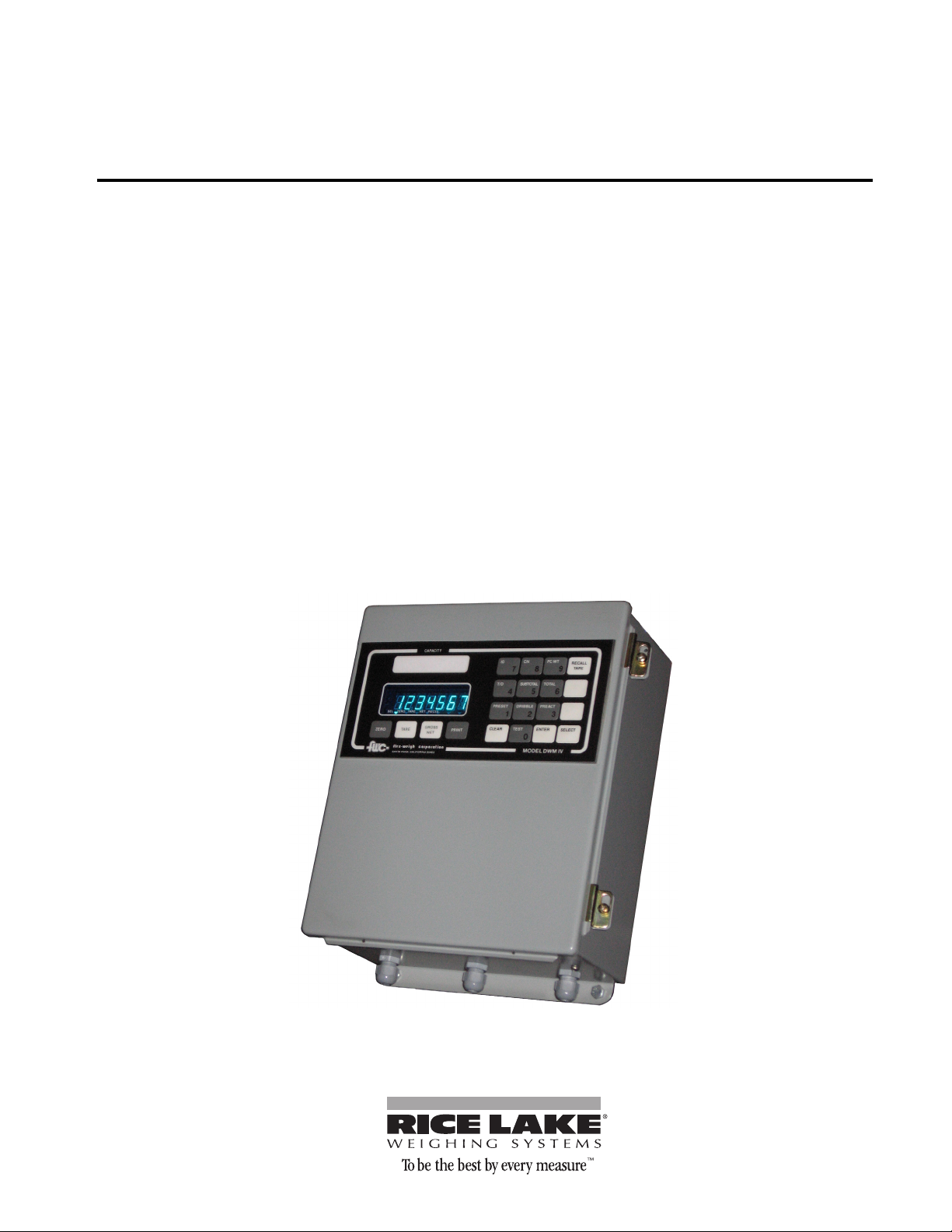
DWM-IV
Digital Weightmeter
Operator Manual
113873
Page 2

Page 3
Page 4

Page 5
Page 6

Data Output: Serial ASCII 20 mA current loop with selectable baud rates (15019.2K),
selectable auto or manual print, continuous data out, or bi-directional communication.
Remote Control Inputs: Zero, Tare, Net/Gross, Print. Requires voltage-free contacts.
Enclosure: NEMA-12 wall mount/dust-tight.
Options:
Outputs: Dual port serial RS-232, RS-422, RS-485, and/or 20mA current loop; Parallel
BCD; Analog 4-20mA or 0-5 VDC.
Time and Date: Battery backed up time and date with selectable 12 or 24 hour mode.
Setpoints: Up to six (6) single speed or three (3) two speed setpoints with Zero
Interlock and Fill Complete output.
Table Stand: Provides 60 degree angle mount stand for wall mount enclosure.
N4S Enclosure: NEMA-4 Stainless Steel watertight wall mount enclosure.
Custom Systems: Flex-Weigh offers full engineering support for customized systems.
Contact your local dealer for further details.
Specifications:
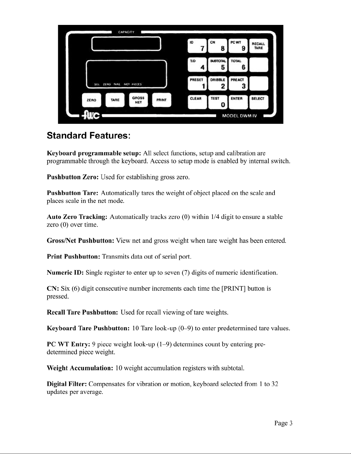
Keyboard: Sealed keyboard with tactile keys.
Display: 6 digits and (-) sign. Seven (7) segment, 0.5" high blue vacuum fluorescent
type, with annunciators for: function select, center zero, tare, net, pieces, F1, and F2.
Internal Raw Count: 100,000 counts maximum.
Display Resolution: 1 part in 10,000 maximum Legal for Trade, 1 part in 24,000
extended, 1 part in 100,000 maximum in high resolution mode.
Display Increments: x1, x2, x5, x10, x20, x50, x100.
Decimal Point Location: Selectable 14 places to the left.
A/D Conversion Rate: 15 updates per second.
Response Time: Zero (0) to full scale capacity, selectable to 0.5 to 4 seconds.
Display Rate: Selectable 0.25, 0.5, 1, 2, 5, 10, or 20 updates per second.
Page 4
Page 7

Over Capacity: Displays OLOADat 102% of Full Scale Capacity.
Center Zero: Light indication when scale is within +/-0.25 digit of center of zero (0).
Load Cell Excitation: 15 VDC, powers up to twelve (12) 350 ohm load cells.
Input Sensitivity: 0.6 to 12 microvolts per digit.
Accuracy: 0.01% of full scale or +/- one digit, whichever is greater.
Data Output: Serial ASCII 20 mA current loop with selectable baud rates (15019.2K),
selectable auto or manual print, continuous data out, or bi-directional communication.
Operating Temperature: -10 degrees C to +40 degrees C (+14°F to +104°F).
Humidity: Maximum: 95% RH non-condensing.
Power: 120 or 240 VAC, 5060 Hz, 25 watts.
Fuse: 1/4A @ 120 VAC, 1/8A @ 240 VAC.
Dimensions: 12" (30.48 cm) H x 10" (25.4 cm) W x 5" (12.7 cm) D.
Weight: 16 lb (7.25 kg).
Page 5
Page 8

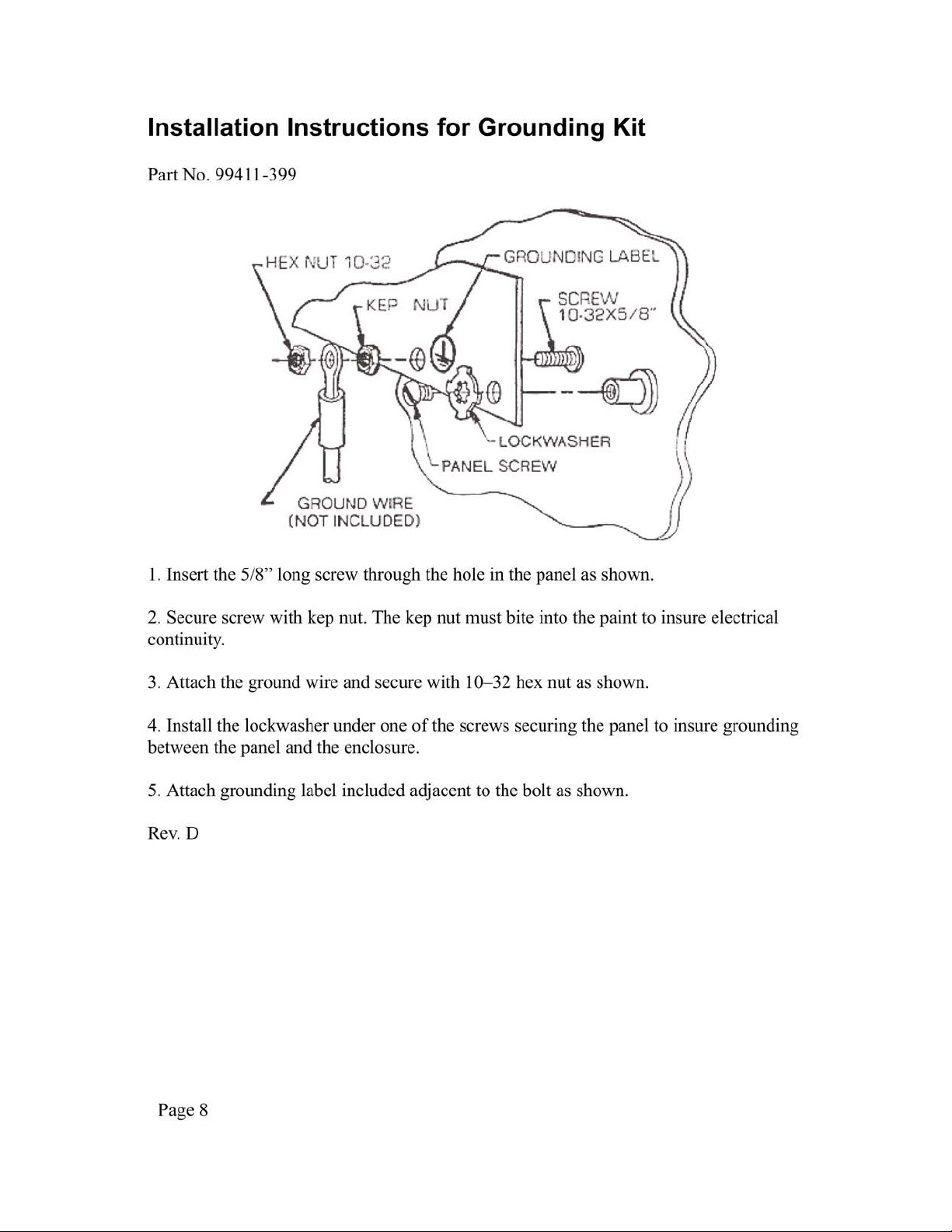
Page 9

Installation Requirements
Maximum performance is guaranteed only when installation of the scale system is
performed by a qualified scale technician. For best performance, the AC mains supplying
the scale system must be an isolated circuit free from other loads and not in close
proximity to inductive or SCR controls.
WARNING: THIS SCALE MUST BE OPERATED FROM AN AC POWER SOURCE
THAT PROVIDES AN EARTH GROUND FOR THE SCALE CHASSIS TO ENSURE
SAFE OPERATION AND PROPER PERFORMANCE. THE POWER CORD IS THE
POWER DISCONNECT DEVICE. CARE SHOULD BE TAKEN NOT TO BLOCK
ACCESS TO THE OUTLET IN CASE OF AN EMERGENCY.
Unpacking and Inspection
Remove the weightmeter display from its shipping container. Discard the protective
materials. Do not plug the meter into an AC voltage source until completing the
inspection of the instrument. With a proper screw driver, loosen the screws holding the
lid clasps in place. Open the lid and visually inspect to make sure there are not signs of
shipping damage such as broken wires, loose components, or fractured printed circuit
boards. This visual inspection is necessary if a shipping claim needs to be processed.
Every care has been taken to minimize potential damage that could occur if rough
handling is experienced in transit.
Handbook 44 Requirements
The following applies to Model DWM-IV weightmeters used on Handbook 44
applications.
1) Wire seal provision is required on access lid.
2) Piece count feature must be disabled (Step F5.0 of SET-UP procedure).
3) RFI (Radio Frequency Interference) protection kit option is required in areas where
RFI is present.
Page 7
Page 10
Page 11

Operating Instructions
A. DISPLAY
The display indicates the arithmetic result of the analog signal derived from the scale
base. The display indicates: OLOAD at 102% of capacity and above.
B. STATUS INDICATORS
The DWM-IV illuminates a triangular arrow above the proper legend for current status of
the display. The status indicators are:
1. SEL - illuminated while accessing the front panel options.
2. ZERO - illuminated when the scale base is within +/- 0.25 increment of zero
3. TARE - when lit, indicates that a tare value is being displayed.
4. NET - when lit, indicates that a non-zero tare value is currently being used.
5. PIECES - illuminated when in the piece count mode to indicate that the display is
showing pieces instead of weight.
6. F1 - Future option. (not labeled on standard units)
7. F2 - Future option. (not labeled on standard units)
C. KEYBOARD
1. [Zero] Button: This button allows re-zeroing of the scale over a +/- 2% range of scale
capacity or full scale capacity (programmable). During set-up, the automatic zero tacking
may be disabled if desired. This button must be pressed for approximately two seconds to
capture zero.
2. [Tare] Button: This button is used to remove the container weight value from the
weight indication. When pressed with weight on the scale no motion present, this tare
value will be stored and subtracted from the gross weight to indicate a net weight display
of zero. Pressing the [TARE] button places the system in net weighing mode.
Page 9
Page 12

3. [Gross/Net] Button: If a tare has been entered, this button will alternately select
between the gross and net weight modes. If the tare has been cleared to zero, the DWMIV will automatically select the gross weight mode. This button will be inactive while the
tare value remains equal to zero.
4. [Print] Button: This button initiates a print cycle to an external peripheral device such
as a ticket printer or computer. The output format may be programmed during the set-up
procedure.
5. [Recall] Tare: The instrument is equipped with a key board to provide a means of
entering a known tare weight. Up to six (6) digits of digital tare may be entered up to the
full capacity. Entries greater than full capacity will be cleared to zero. The least
significant digit (LSD) is automatically rounded to conform to the pre-programmed
instrument LSD. Press the [RECALL TARE] button then a numeric button corresponding
to the tare register desired (if ten (10) tare look-up feature is enabled) and the [ENTER]
button. The previously displayed data will be shown. Enter the required value and press
[ENTER]. This value is then stored in memory. A non-zero value places the system in net
weighing mode.
6. [Select]: This button is used to access the pre-programmed front panel functions as
indicated on the corresponding buttons zero through nine.
7. [Clear]: Used to clear a mistaken entry while in one of the data entry modes.
8. [Enter]: This button is used to store data into memory and also to sequence through the
data entry procedure.
Page 10
Page 13

D. FRONT PANEL FUNCTIONS
TEST Allows the operator to test the integrity of the weight display by sequentially
lighting each segment of all digits, all segments, and each arrow indicator. These results
show that all drivers and displays operate in both the on and the off conditions.
PRESET The DWM-IV provides up to eight (8) outputs which may be used to control
solid state relays. The system may be configured for three (3) two-speed or six (6) singlespeed, cascaded setpoints. In addition, zero interlock and FILL COMPLETE outputs are
provided which, when used with additional, external hardware, may be used to simplify
batching operations. Enter the weight value desired for each preset starting with number
zero through to number three (3) or six (6). The zero interlock preset is number zero. If it
is desired to merely view the presets already in memory, simply press [ENTER] without
pressing any numeric buttons or [CLEAR]. The weight values will be displayed from
zero (0) to three (3) or six (6) then return to normal weight display mode.
DRIBBLE The value entered as the dribble amount is subtracted from the final
setpoint (PRESET-PREACT) and this amount is the fast feed cut-off setpoint. It
represents the amount of material desired to be filled at the slow rate. The values are
entered in the manner as described for PRESET above where number one (1) corresponds
to PRESET number one (1) above, etc. This function is only active if the two-speed
configuration has been selected.
PREACT Enter the value of weight that is to be subtracted from the preset value in
computing the final cut-off value for the output. This value represents the amount of inflight material.
T/D This function allows the operator to enter the current time and date for print-out
purposes. The time and date option must be installed and enabled for this feature to be
operative.
Page 11
Page 14

SUBTOTAL The DWM-IV contains ten (10) registers for weight accumulation. The
subtotal of all previously recorded weights or pieces may be recalled and/or printed using
this button. The totals registers remain intact after use.
TOTAL The totals may be viewed/printed as described in SUBTOTAL above with the
exception that after printing, the current total register is cleared to zero along with the
consecutive numbering register. The current register used for totalizing is selected by this
function.
ID The ID function allows the operator to enter up to seven (7) digits of numeric ID.
The current value of ID is displayed and may be changed by use of the numeric and
[ENTER] buttons.
CN The consecutive number may be viewed or changed using this button. The CN is
automatically cleared to zero by totalizing but may be initialized to any value by use of
the numeric buttons. The CN increments before a print cycle begins, as initiated by the
[PRINT] button.
PC WT This function allows the instrument to be used for piece counting by entering
the known weight per piece. This mode is automatically selected if the current piece
weight register is OTHER than zero. The front panel indicator for PIECES will illuminate
while in the pieces mode. Any of nine (9) different registers may be selected with
different piece weight factors.
Page 12
Page 15
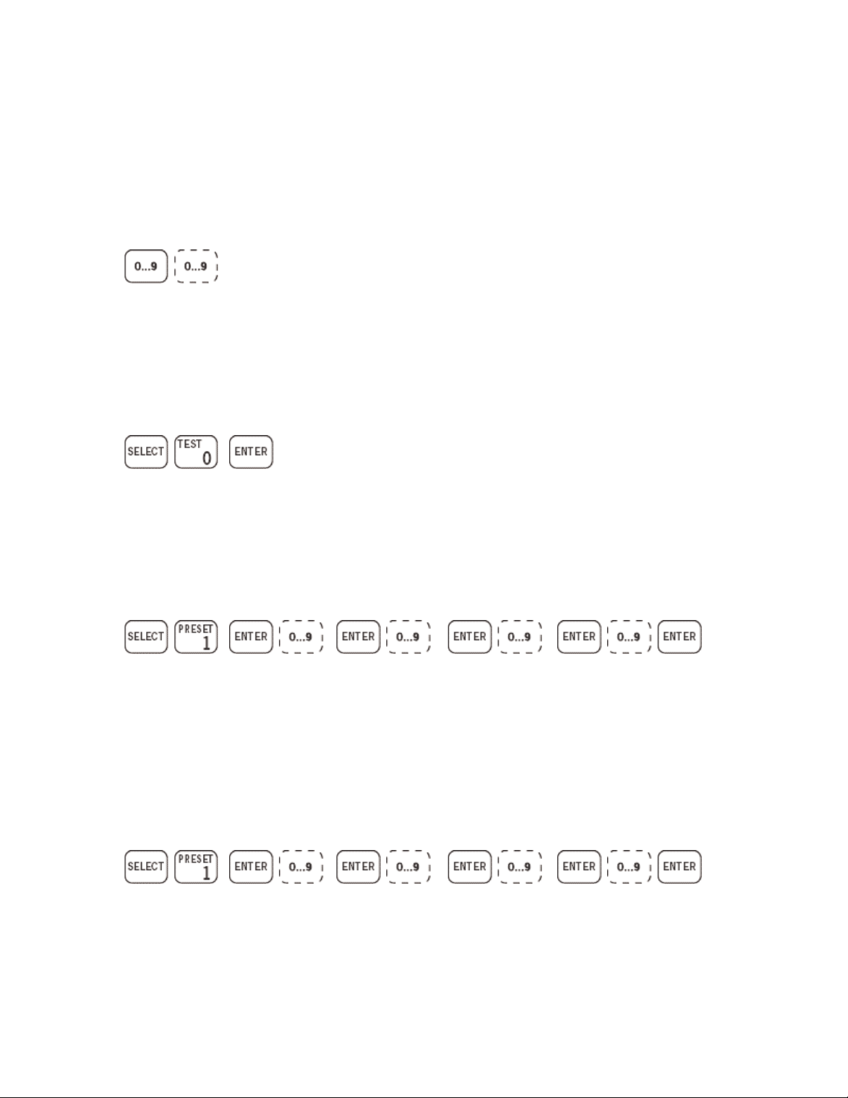
Front Panel Data Entry
Select the desired function from the examples given below. Then press
the buttons in the order shown from left to right. The following
symbols are used to indicate numeric button entry which may be
comprised of multiple numeric entries.
The dotted line symbol indicates that numeric entry at this point in the
sequence is not required unless the data are to be changed.
FUNCTION 0: TEST all display segments.
FUNCTION 1: PRESET entry of weight values. Two speed feed
enabled.
Preset
0
FUNCTION 1: PRESET entry of weight values. Single speed feed
enabled.
Preset
0
Preset 1 Preset 2
Preset 1
Preset
2-5
Preset
3
Preset
6
Page 13
Page 16
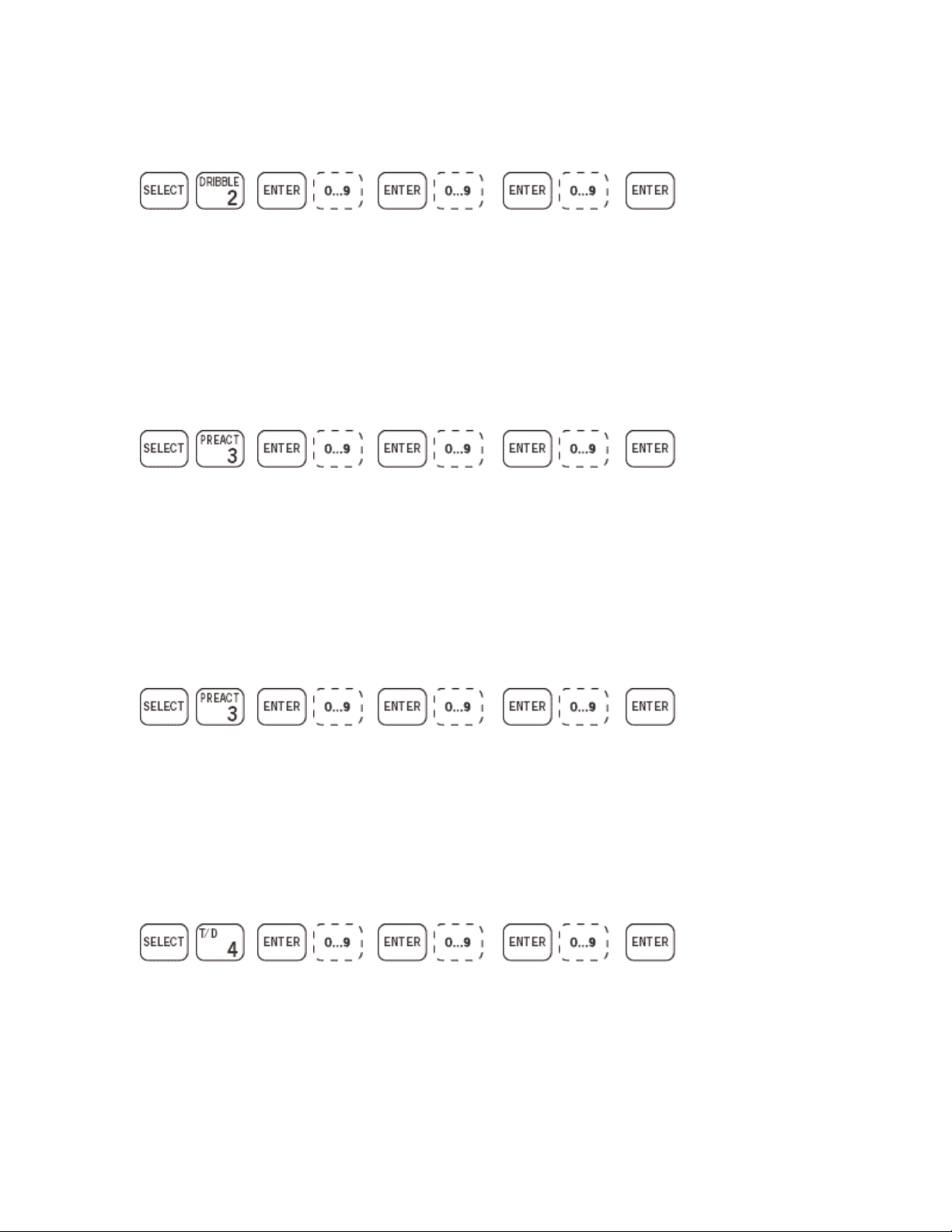
FUNCTION 2: DRIBBLE entry of weight values.
Dribble
1
FUNCTION 3: PREACT entry of weight values. Two speed feed
enabled.
Preact
1
FUNCTION 3: PREACT entry of weight values. Single speed feed
enabled.
Dribble
2
Preact 2
Dribble
3
Preact
3
Preact
1
FUNCTION 4: T/D Time and Date Entry - 12 Hour Mode.
Date Time
Page 14
Preact
2-5
Preact
AM-
6
PM
Page 17
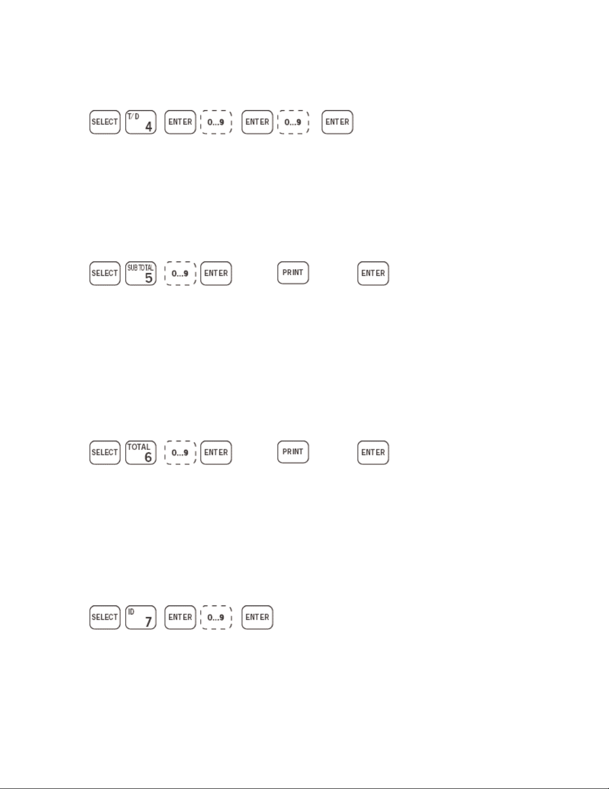
FUNCTION 4: T/D Time and Date Entry - 24 Hour Mode.
Date Time
FUNCTION 5: SUBTOTAL Subtotal viewing or printing of selected
register.
or
Reg #
FUNCTION 6: TOTAL Total viewing or printing of selected register.
Also selects the current register.
Reg #
Prints
Subtotal
or
Prints
Total
Exits.
No
Printing
Exits.
No
Printing
FUNCTION 7: ID Numeric ID entry of up to seven digits.
ID
Page 15
Page 18
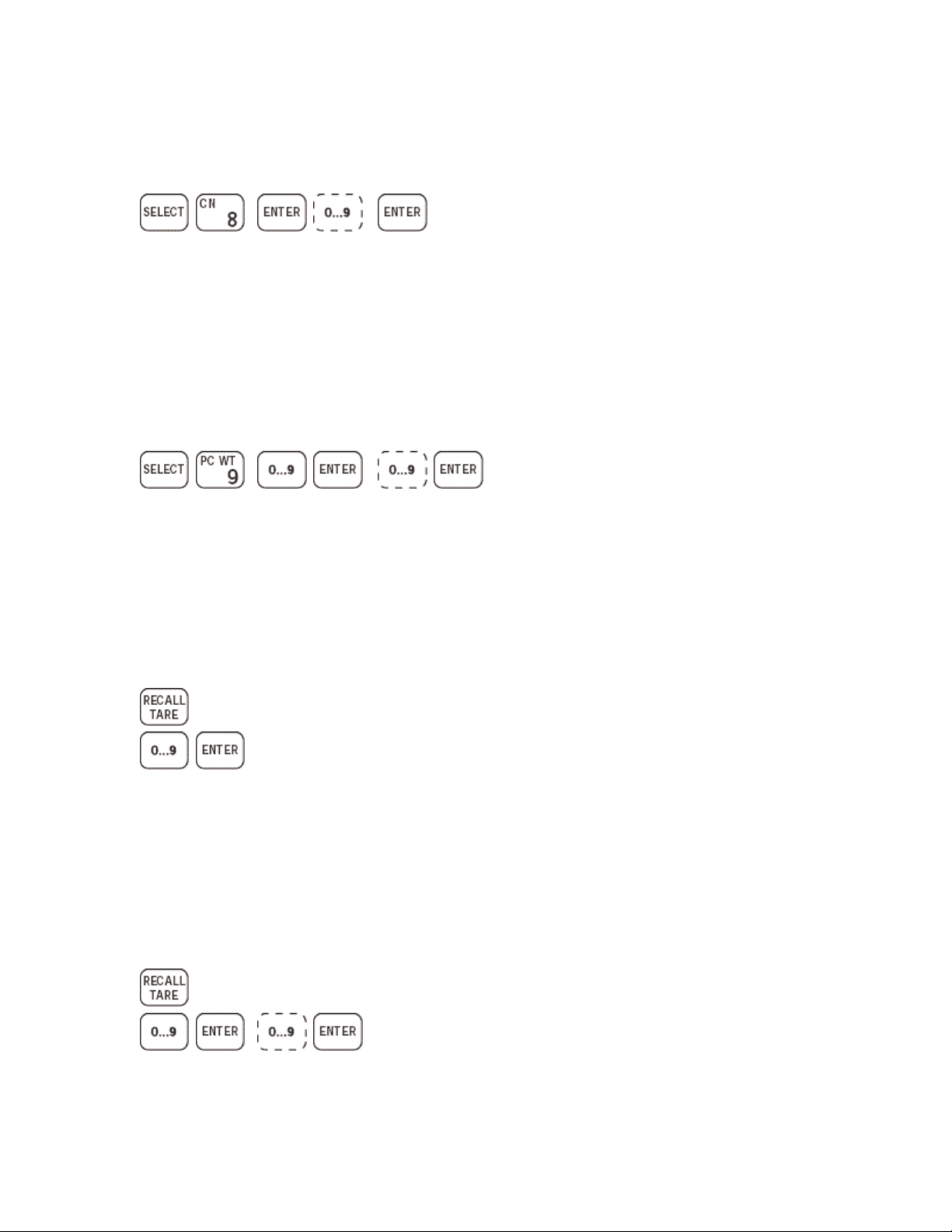
FUNCTION 8: CONSECUTIVE NUMBERING CN viewing or
changing.
CN
FUNCTION 9: PIECE WEIGHT Weight per Piece Entry and Piece
Mode Selection. Note: Selecting Register 0 will disable the piece
counting mode and return the display to the weight mode.
Pc Wt
Reg #
RECALL TARE: Keyboard Tare Entry of Known Tare Value.
Tare
Weight
RECALL TARE: Keyboard Tare Entry (Ten Tare Look -up)
Pc Wt
Page 16
Tare
Reg
Tare
Weight
Page 19

How to Enter and Exit System Setup
Locate the small dip switch block in the lower right corner of the mother board. Turn on
S1, the display should then show FSE F1.
From the FSE Fn display you may scroll forwards and backwards using the [TARE] and
[ZERO] buttons. When the page you want is displayed, press [PRINT] to accept and view
the first step in that page.
Example: If the setup switch S1 is turned on, the display will show FSE F1. Press
[ZERO] button. The display will show FSE F6, press [PRINT], display will show F6.0 n.
You may now change the current setting for F6.0 by pressing [TARE], accept the setting
by pressing [PRINT], or backup to F5.9 by pressing [ZERO].
You may also go directly to the page you wish to change by pressing the pa ge number
minus 1 on the keypad, after S1 is turned on. (Example: Operate S1. Display shows FSE
F1. Press 3. Display shows FSE F4.)
Upon completion of your changes you may exit and save without having to go all the way
to the end of the setup steps by pressing the [F1] button (on most units this will be an
unlabeled button under [RECALL/TARE], second down from the top, on the right hand
side). The display will go to FCd0. Press [PRINT] to save changes or press [TARE] to
change option to 1 or 2. Option 1 will discard all changes you have made (you can also
do this by turning off S1 at any time before the display shows FILEd. Option 2 (not
available on earlier software) is used to reset the factory defaults into the EEPROM
where all of the setup data is stored (U14 under the A/D board.).
Once you have selected which FCd option to use (usually 0 which is how it comes up
automatically) save your selection by pressing [PRINT] after about a second the display
should read FILEd, at this time you may turn off the setup switch S1 and return to the
weighing mode.
Function Select Enable Descriptions:
F1 Contains settings that control the overall operation of the scale, such as averaging,
update rate, motion detection, zero tracking, etc.
F2 Tare functions, setpoint options & powerup options are set here.
F3 Serial port parameters, enabling of print fields, and custom formatting.
F4 Serial data output formats, modes.
F5 Enables individual right hand keyboard functions.
Page 17
Page 20

F6 Calibration, capacity and increment size selection.
F7 Only available on custom systems.
Configuration Setting Descriptions
F1.0 Raw Counts Display
Enable Raw counts mode is used for diagnostic purposes and is also useful for
precalculating calibration settings. Once enabled, it will display the internal counts from
the A/D (analog/digital) converter which should fall between 250-100,000 counts on
standard software. If your display is showing top or bottom dashes it is already out of
range and raw counts will show the same indication. Check your wiring and millivolt
output from the load cell(s). This is the only configuration setting that does not have to be
written to permanent memory to take effect, just push [TARE] to set it to E, press
[PRINT] to accept the setting and turn off S1. The display will show all of the
annunciator arrows to show that it is in raw counts mode. To disable raw counts and
return to normal weighing, either repeat the above procedure setting to d, or simply
remove power. When you power the system back up raw counts mode will be disabled.
F1.1 Digital Averaging
Used to increase the stability of the weight readings. Higher settings will make the
display more stable in a noisy environment (wind, vibration, etc.), but will slow down the
display response. Lower settings will speed up the response but may cause excessive
motion and jitter in the display.
F1.2 Display Update Rate
This setting controls how often new readings are sent to the display. Higher settings will
make the display more responsive and give more of a scrolling number effect. Lower
settings will cause readings to appear to change all at once and may mask some
instabilities.
F1.3 Motion Detection
This controls how much the readings have to change to cause motion to be detected.
Motion detection is used to prevent printing, taring and zeroing of the scale when the
weight is unstable.
F1.4 Auto Zero Tracking Enable
F1.5 Auto Zero Tracking Width
Page 18
Page 21

Used to control the automatic ZEROING of the scale. It will automatically track small
drifts in weight such as caused by small amounts of debris, rain, or thermal drift.
Tracking width sets how much drift can be automatically zeroed out. Example, if you
have a truck scale with 20 lb increments and your tracking width is set to 3, anything that
weighs 60 lb or less will be zeroed out. This may not be desirable if you are using your
system for filling/batching and have a very slow fill rate or if you are trying to weigh
very small items (which is not recommended) as the tracking may happen faster than you
are filling and will cause it to appear that the scale is not working.
F1.6 - 2% Zero Range
Will prevent the scale from being Zeroed if the reading is more than 2% of the capacity
set in F6. Useful to prevent accidental re-zeroing and subsequent restarting of batch
systems when a batch is already being processed.
F1.7 Right Hand Keyboard Enable
Turns on/off the right hand side of the keyboard. Has no effect on the four (4) function
buttons under the display.
F1.8 Output Options
Controls the function of the J4 connector on the mother board. Should be disabled if not
used as it will slow down the system.
F1.9 High Resolution Mode
Allows you to bypass the normal four (4) raw counts per digit requirement that would
limit you to about 24,000 display units. You should not use this unless necessary as
neither the internal circuitry of the A/D board nor the load cells connected to it were
designed for such extremes.
F2.0 Tare Enable
Controls whether or not the front panel [TARE] button will operate. The tare function
should be used to remove an empty container weight without having to zero the scale.
When the [TARE] button is pushed the scale will enter the tare weight automatically and
switch to the net mode. You can switch between the gross mode and net mode using the
[GROSS/NET] button.
F2.1 Tare Interlock
Prevents the tare from being cleared if the scale is not at zero. Used mostly to prevent the
accidental clearing of the tare value while it is still in use.
Page 19
Page 22

F2.2 Auto Clear Tare
Causes the tare value to be cleared automatically when the scale returns to zero. Use this
to force entry of a new tare weight for each container being used (such as in a recycle
center application, where you have multiple bins).
F2.3 Ten Tare Look -up
Enables the storage of up to ten (10) tare values. You can use this to store the tare values
for several containers and retrieve them by register number as needed.
F2.4 Battery Back-up Enable
Prevents values in the random access memory from being cleared by a power-up
sequence. This consists of ID numbers, Consecutive Numbers, tare values, preset,
dribble, preact, totals, etc. Revision D and higher mother boards have a 24-hour back-
up circuit built-in. This can be extended to approximately ten (10) years on all mother
boards with an addition of a time/date module.
F2.5 Stand-by Mode on Power-up
Will cause the display annunciator arrows to light upon power-up. The display will be
disabled until either the [ZERO] or [TARE] buttons are pressed. Required by Weights
and Measures in some areas to show that a power failure has occurred.
F2.6 External Gross/Net Enable
When enabled the front panel [GROSS/NET] button will not operate. The system will
instead take an input (contact closure) from TB1-3 of the mother board. Unlike the front
panel switch this input is closed for net and open for gross.
F2.7 Two-Speed Feed
Part of the preset function, enables the [DRIBBLE] button on the front panel. The value
in the dribble will be subtracted from the preset, and used to operate the two speed relay
function. If enabled there are three (3) presets, disabled there are six (6).
F2.8 Sequential Feed
Controls how the output relays (connected to J7) operate during two-speed feed
operation. When disabled, both the slow and fast feed relays are energized initially. The
fast feed relay is de-energized when the weight reaches the preset minus the dribble
value. The slow feed relay is de-energized when the preset weight minus the preact is
reached.
Page 20
Page 23

When this setting is enabled, only the fast feed relay is initially energized. The fast feed
relay is de-energized and the slow feed relay is simultaneously energized when the
weight reaches the preset minus the dribble value. The slow feed relay is de-energized
when the preset weight minus the preact is reached.
F2.9 Invert Relays
If enabled the On/Off function of the output relays (J7) is reversed. The relays will be off
below the presets and turn on as they are reached. Exception: relays K7 and K8 (fill
complete and zero interlock) are not affected by this setting.
F2.A Parallel Feed
Allows presets to operate independently of each other. In this mode presets can be set to
any value. It is not necessary for each preset to be of a higher value than the one before it.
Each output will operate as if it were the only one. If disabled the outputs operate
sequentially. First preset one (1) and then preset two (2), then preset three (3), etc. The
value of each preset must be higher than the one before it for the system to operate
properly.
F3.0 Baud Rate
Used to set the baud rate (speed) of all serial ports. Serial data is available at TB2 and J6
on the mother board. This must be set the same as the device to which it is connected.
F3.1 Parity
The checksum bit used in serial communication. It can be even, odd or none. This is also
where you would set the number of data bits (7 or 8). This must be set the same as device
to which it is connected.
F3.2 Checksum
This checksum is for an entire data stream (one line of print, etc.) as opposed to parity
which is for one character. It is used during communications to verify that the received
data contains no errors.
F3.3 Delay After Carriage Return/Line Feed
Used to cause the system to pause after a carriage return. Needed with some devices to
allow the data which was just sent to be processed (such as some older printers without
buffering). If not needed set to 0 as it slows down the system.
Page 21
Page 24

F3.4 Consecutive Number Print
F3.5 ID Print
Controls whether or not these items will be included in the data sent out of the serial port
(such as to a printer).
F3.6 Negative Print Enable
Allows printing of negative weight readings. This is not allowed in Legal for Trade
applications.
F3.7 - 24-Hour Clock
If enabled and you have a time/date module, all times will be in Military Time (24
hour). If disabled, times are 12 hour AM/PM.
F3.8 Preamble/Postamble/Custom Formatting
Note: When this step is entered, F3.8 is not displayed. The display advances
immediately to the preamble entry field, FF FF FF.
This is used with the serial ports. It allows you to add characters to the beginning and
ending of the data stream. For example, this can be used to cause a printer to reset or
change the print size at the beginning of a print, and reset, cut-off or paper release at the
end of a print. Only three (3) preamble and three (3) postamble characters are allowed.
All preamble and postamble values are in hexadecimal (base 16, 0-9, A-F). If not used
they should be set to FF. Note, that if custom print formatting has been enabled in
F4.7 or F4.8 custom print formatting will begin after the postamble has been entered.
All custom print formatting is done in decimal (base 10, 0-9). Custom print formatting
consists of two (2) pages. The first is used for normal print output (F4.7) and is ended by
the first 255. The second is used for totals printing (F4.8) and is ended by the second
255.
F4.0 Print Mode
Controls how prints are initiated. 1 is the normal setting and will latch the request for
print from any input (front panel [PRINT] button, contact closure TB1-1, print command
from bi-directional interface) and print when stable weight data is available as per F1.3.
2 will only print if the weight data is stable as per F1.3 at the time the request is made.
3 is autoprint and will print based on F1.3, F4.2 and F4.3 without an external request.
Print data is available on TB2 of the mother board or from channel 1 (demand) of DDO
(dual-data output) option board which, if installed, is connected to J6.
Page 22
Page 25

F4.1 Continuous Data Format
Selects the data format used for continuous data output. Normally used for remote
displays and scoreboards and in some computer applications. This data is available from
TB2 of the mother board and from channel 2 (continuous) of the DDO (dual-data
output) option board which, if installed, is connected to J6. Note, that if both demand and
continuous data are used the data on TB2 will contain both data streams and may cause
errors. Therefore, if both demand and continuous data are to be used it is recommended
that they both be connected to the DDO board. If this function is not used, disable it as
it will slow down the system.
F4.2 Weight Change Percentage
Used with the auto-print function in F4.0. Specifies the percentage of change based on
full capacity (as set in the calibration procedure (F6)) necessary to rearm the auto-print.
For example, if your scale has a capacity of 100,000 lb and F4.2 is set to 15%, a weight
change of 15,000 lb would be required to rearm the auto-print.
F4.3 Minimum Print
Used with the auto-print function in F4.0. Sets the number of increments (as set in F6.1
and F6.2) above zero required before the auto-print is allowed to function. For example,
if F6.1 is set to 20 and F6.2 is set to 0 and F4.3 is set to 30 then the auto-print will
not operate until the weight on the scale exceeds 600 lb. This would be useful on a truck
scale to prevent prints occurring when people walk across the scale.
F4.4 Bi-Directional Communications
Any function that can be performed from the keyboard can be performed through the bidirectional interface. Connection to this interface is provided on TB2 on the mother board
(in current loop) If a current loop device is not available and RS232 is needed then a
DDO option board must be installed and connected to J6 on the mother board and the
built in current loop input port must be disabled by cutting JP1 located just below J3 and
to the left of J6 on the mother board. The response rate on this function is very low. Send
the data as slowly as possible to avoid errors. Disable this function if not used, as it may
pick up random noise.
F4.5 Weight Data Format
Controls the way weight data is sent out to the serial ports. Setting 0 {Displayed weight
only} will send whatever weight is currently displayed whether it be gross or net. Setting
1 {Single line gross/tare/net} will send a gross/tare/net string with only one (1) CR/LF
at the end. If the display is in the net mode, this will put all three (3) items on one (1) line
(if there is room. See printer for more information). Setting 2 {Multiple line
gross/tare/net} will send a gross/tare/net string with a CR/LF after each item. If the
display is in the net mode, this will put each item on its own line. Setting 3 {Status
Page 23
Page 26

weight and tare} should be used when communicating with a computer. It contains
information on the current modes and status of the system sufficient to compute the
gross, tare and net and whether the scale is in gross or net mode.
F4.6 Time and Date Format
Controls the order in which time and date is printed.
F4.7 Print Format
Controls the order print data items are sent out to the port.
F4.8 Total Format
Controls the order totals items are sent out to the port.
F4.9 Weight Accumulation
Causes a running total based on displayed weight to be maintained. There are a total of
ten (10) registers that can be used to store totals. To view a current total without clearing
it or to select a new accumulation register use the sub-total function. To view and clear
totals use the total function. Note: You dont have to use the same total and sub-total
registers, you can total one while accumulating to another.
F5.0 Piece Weight Enable
Enables the front panel [PC WT] button. This function is used for counting. You are
given nine (9) registers in which you store weight values for single items. When a register
is selected the weight on the scale is divided by the value in the register and the number
of items is displayed. To turn this function off and return to the normal weighing mode,
set the register to 0. Note, that this counting function is limited to display resolution
and will not be as accurate as a dedicated counting scale it is provided for convenience
only. This mode must be disabled in Legal for Trade applications.
F5.1 Consecutive Number
Enables the front panel [CN] button. This allows you to view and set a consecutive
number which may be printed. It will automatically be incremented by one each time a
print is performed.
F5.2 ID Number
Enables the front panel [ID] button. This allows you to view and enter ID values, used
only for printing.
Page 24
Page 27

F5.3 Total/SubTotal
Enables the front panel [TOTAL] and [SUBTOTAL] buttons. This allows you to view
and clear totals data.
F5.4 Time and Date
Enables the front panel [T/D] button. Allows you to set the time and date.
F5.5 Presets
Enables the front panel [PRESET], [PREACT], and [DRIBBLE] (if F2.7 is enabled)
buttons. Allows setting of set points. This includes the zero interlock value which is
displayed as set point 0 (this value should never be set to 0, and should always be less
than the first set point). Any unused set points should be set to 0. Set point outputs are
provided on J7 of the mother board. These outputs are TTL compatible. If other voltage
levels are needed a solid-state opto-coupled relay board is available as an option. Specify
AC or DC output and voltage level when ordering.
F5.6 Recall Tare
Enables the front panel [RECALL TARE] button. This button allows you to view the
current tare value and change it if necessary. If F2.3 is enabled it also allows you to select
the current register being used. This is the button you use to enter keyboard tares. Both
the [TARE] and the [RECALL TARE] buttons store their values in the same register.
F6.0 Weight Units Used for Printing
Controls the weight unit abbreviation used in printing and has no effect on the display.
For example, if the scale display shows 100 and you press [PRINT] you would get 100
lb on your printout if F6.0 is set to 0 and 100 TONNE if F6.0 is set to 4. Note,
that no units conversion takes place; only the unit name is changed.
F6.1 Increment Size
Sets the count-by size used for displaying weights. For example, a setting of 20
would allow a minimum display of 20 and would count by 20. Note, this leaves a dead
zero and if you set a decimal point position the dead zero will remain.
F6.2 Decimal Position
Sets where the decimal point will be. Example, if you want an increment size of .002
set F6.1 to 2 and F6.2 to 3. Note that increasing the decimal position by one will
increase the number of counts displayed by 10 times. Maximum display resolution is
Page 25
Page 28

normally approximately 20,000 counts. To compute the number of counts divide the set
capacity by the increment size.
F6.3 Enter Cal Mode
This is how you calibrate the scale. Enable this and continue on to F6.4. If you do not
enable it you will advance to CAL d (calibration done) and the calibration will be
unchanged and you will exit from set-up mode.
F6.4 Linearity
Allows you to correct for small linearity errors in the middle of the weight range. This is
not allowed in Legal for Trade applications. If not used, this should be set to 0 if set
to -0, linearity will not be affected but you will be required to place full capacity
weight for calibration.
Set-Up Procedure
Place the internal CAL switch (S1-1) to the ON position. The scale must be configured
before operation by programming the needed parameters. Use the following front panel
switches to view and/or change existing data values:
[ZERO] Used to scroll backward through the programming sequence steps.
[TARE] Used to scroll forward through the programming sequence steps when in
function select mode and to sequence through available choices of individual functions.
[PRINT] Used to accept displayed data then to advance one step in the programming
sequence.
[CLEAR] Used to return to the Function Select Enable portion of the SET-UP procedure.
[F1] Used to advance to the end of the SET-UP procedure to save or discard the changes
entered. This button is not labeled and is located below the [RECALL TARE] button.
FSE Function Select Enable Selects the starting function group to be programmed. Use
[ZERO] and [TARE] buttons to move back and forth through this menu. Press print to
enter that section at the first item.
Choices: F1, F2, F3, F4, F5, F6 (F7 on some custom systems)
FSE F1
F1.0 Raw Counts Display Enable
d - Show normal counts on display.
Page 26
Page 29

E - Display the internal raw counts.
F1.1 Digital Averages
Number of A/D conversions which comprise the running average.
Choices: 1, 2, 4, 8, 16, 32
F1.2 Display Update Rate
Number of display updates per second.
Choices: 20, 10, 5, 2, 1, 0.50, 0.25
F1.3 Motion Limit in Digits
Select the width of the motion window by use of the TARE key. A selection of d will
disable the no-motion requirement for use by the zero, tare and print functions.
Choices: 0.5, 1, 2, 3, 4, 5, 6, d
F1.4 Auto zero tracking Enable
d - AZT disabled.
E - AZT enabled.
F1.5 Auto zero tracking width
Number of digits over which zero will track.
Choices: 0.5, 1, 2, 3
F1.6 Two Percent Zero Range Enable
d - Zero active at any weight.
E - Zero active to +/-2% of capacity about zero.
F1.7 Key Functions Enable
d - All right-hand keys disabled.
E - All key functions enabled.
Page 27
Page 30

F1.8 Output Options
d - Neither of the following options installed.
1 - Analog output card installed.
2 - BCD output card installed.
F1.9 High Resolution Enable
d - Minimum four raw counts per digit.
E - Minimum one raw count per digit.
FSE F2
F2.0 Tare Enable
d - Tare disabled.
E - Tare enabled.
F2.1 Tare Interlock
d - Tare may be changed at any weight indication.
E - Weight must be at zero to clear tare.
F2.2 Auto Clear Tare
d - Not Active.
E - Tare will automatically clear when indication returns to less than 10 positive digits of
zero and no motion.
F2.3 Ten Tare Look -Up
d - Provides single tare register.
E - Enables ten register tare look-up.
F2.4 Battery Option Enable
d - Battery backed option not installed.
E - Battery backed option installed.
Page 28
Page 31

F2.5 Enter Stand-By Mode on Power-Up Enable
d - Weight indication appears after display test.
E - Weight display will be disabled and all status indicators will be on until zero or tare
button is pressed.
F2.6 External Gross/Net Enable
d - Front panel gross/net switch active.
E - External gross/net input determines the mode of weight.
F2.7 Two Speed Feed Enable
d - Single speed outputs (six presets).
E - Two speed feed active (three presets).
F2.8 Sequential Feed Enable
d - Relays act in parallel fashion; both fast and slow relays energize below preset.
E - Relays act in sequential fashion; fast relay energizes, then slow relay energizes.
F2.9 Invert Relays Enable
d - RLY1 through RLY6 non-inverted output.
E - RLY1 through RLY6 inverted output. RLY7 (Fill Complete) and RLY8 (Zero
Interlock) remain as before.
F2.A Parallel Feed Enable
d - Relays operate in sequential order.
E - Independent action of relay output.
Page 29
Page 32

FSE F3
F3.0 Baud Rate Selection X100
Select the desired BAUD rate according to the chart. Older DDO boards have a limited
rating on the current loop ports of 1200 BAUD. If Continuous Data output is selected,
BAUD rate should be 2400 or greater.
Choices: 192, 96, 48, 24, 12, 6, 3, 1.5
F3.1 Parity Selection
d - 7 Bits, No Parity.
1 - 7 Bits, Even Parity.
2 - 7 Bits, Odd Parity.
8b - 8 Bits, No Parity.
8be - 8 Bits, Even Parity.
8bo - 8 Bits, Odd Parity.
F3.2 Checksum Transmit Enable
d - No checksum
E - Checksum transmitted, prior to CR-LF, as the 2s compliment of previously sent
characters.
F3.3 Delay After CR-LF
The amount of delay, after a carriage return or line feed is transmitted, in seconds.
Choices: 0, 0.1, 0.2, 0.5, 0.75, 1.0, 1.5
F3.4 Consecutive Number Print Enable
d - Disable the printing of the CN.
E - Enable the printing of the CN.
Page 30
Page 33

F3.5 ID Print Enable
d - Disable the printing of the ID.
E - Enable the printing of the ID.
F3.6 Negative Print Enable
d - Disable printing of negative weights.
E - Enable printing of negative weights (non HB44).
F3.7 24 Hour Clock Enable
d - 24 hour clock disabled (12 hour with AM/PM).
E - 24 hour military time enabled.
F3.8 Preamble Characters
xxxxxx Enables the user to define up to three characters to be sent at the beginning of a
print. The characters are entered in hexadecimal. A value of FF is not transmitted. The
front panel keys are re-defined during this step as follows:
ZERO - Decrements current digit.
TARE - Increments current digit.
GROSS - Selects next digit to the right.
PRINT - Accepts displayed value and advances to next step.
xxxxxx Postamble Characters
Enables the user to define up to three characters to be sent at the end of a print as above
for Preamble.
FSE F4
F4.0 Print Mode
d - Print output disabled.
1 - Print button latches Print Request. Printing will occur when motion ceases and scale
positive.
Page 31
Page 34

2 - Print will occur if not in motion and positive at the time Print button is pressed.
3 - Auto print after motion and positive weight is above value specified in F4.3 below
and change greater than the value specified in F4.2 below has occurred.
F4.1 Continuous Data Format
d - Continuous output disabled.
1 - Status, weight, and tare data sent.
2 - Z660 Scoreboard output.
3 - Remote display, RD-IV, output.
4 - Straight ASCII output only with preamble and postamble sent.
F4.2 Weight Change Percentage
The following values specify the percentage change of Full Scale Capacity before the
auto print latch is re-armed.
Choices: 5, 10, 15, 20, 25%
F4.3 Minimum Print
Digits above zero before auto print is latched.
Choices: 0, 10, 20, 30
F4.4 Bidirectional Communications
d - Bidirectional communications disabled.
1 - Bidirectional communications to customer computer enabled and configured for halfduplex operation. Information sent to the weigh meter is not echoed.
F4.5 Weight Data Format
0 - Displayed weight only.
1 - Single line Gross, Tare, Net.
2 - Multiple line Gross, Tare, Net.
3 - Status, Weight and Tare.
Page 32
Page 35

F4.6 Time/Date Print Format
d - Time/Date printing disabled.
1 - Time then Date printed.
2 - Date then Time printed.
3 - Time only printed.
4 - Date only printed.
F4.7 Weight, Time/Date, ID and CN Print Format
0 - Weight, ID, Time/Date, CN
1 - ID Time/Date Wei ght, CN
2 - ID Time/Date, CN Weight
3 - ID Time/Date CN Weight
4 - Time/Date ID CN Weight
5 - Time/Date ID Weight, CN
6 - ID, Time/Date, CN Weight
7 - ID Time/Date CN, Weight
C - Custom Weight Print Format Enable
F4.8 Total, Time/Date, ID and CN Print Format
0 - Total, ID, Time/Date, CN
1 - ID Time/Date Total, CN
2 - ID Time/Date, CN Total
3 - ID Time/Date CN Total
4 - Time/Date ID Total CN
5 - Time/Date ID Total, CN
Page 33
Page 36

6 - ID, Time/Date, CN Total
7 - ID Time/Date CN, Total
C - Custom Totals Print Format Enable
F4.9 Weight Accumulation Enable
d - Disable weight accumulation and print out.
E - Enable weight accumulation of all previous displayed weights printed.
FSE F5
F5.0 Piece Weight Enable
d - Piece Weight entry disabled.
E - Piece Weight entry enabled.
F5.1 Consecutive Number Enable
d - Consecutive Number function disabled.
E - Consecutive Number function enabled.
F5.2 ID Number Enable
d - ID Number function disabled.
E - ID Number function enabled.
F5.3 Total-Subtotal Enable
d - Total and Subtotal functions disabled.
E - Total and Subtotal functions enabled.
F5.4 Time/Date Enable
d - Time/Date entry function disabled.
E - Time/Date entry function enabled.
Page 34
Page 37

F5.5 Presets Enable
d - Preset, Dribble, and Preact disabled.
E - Preset, Dribble, and Preact enabled.
F5.6 Recall Tare Enable
d - Recall Tare entry disabled.
E - Recall Tare entry enabled.
Calibration Procedure
FSE F6
F6.0 Weight Units used for Printing
d - No weight units printed.
0- Lb
1- kg
2- g
3- Ton
4 - Tonne (metric ton)
5- oz
6 - oz troy
F6.1 Increment Size
Least significant digit increment size.
Choices: 1, 2, 5, 10, 20, 50, 100
F6.2 Decimal Position
Display decimal position from none to four places to the left.
0 - No decimal
Page 35
Page 38

1- .X
2 - .XX
3 - .XXX
4 - .XXXX
F6.3 Enter CAL Mode
d - Continue to last step (CAL d)
E - Enter CAL mode.
F6.4 Linearity Factor
Corrects non-linearity in weigh system. The value required is determined
empirically. Amount of correction depends upon percent usage of the load cell as
well as the system capacity and resolution.
Choices: 7 to -7
E SCALE Empty Scale
Remove all weight from the scale and then press the [PRINT] button.
888888 Full Scale Capacity
888888 indicates the previously entered Full Scale Capacity in even units. Use the
numeric keyboard to enter the Full Scale capacity. Press the [ENTER] button to
advance to the next step.
15 SEC Zero Setting Fifteen Second Delay
Counts down from 15 to zero to capture the zero setting. If the [SELECT] button is
pressed during the time-out period, the meter will immediately terminate the delay
and ignore the motion criterion to capture the weight. Allow at least three (3)
seconds after weight has been applied to the scale before pressing [SELECT] or the
weight captured may be erroneous.
Add Ld Add Load or Add ALL
The weight applied must be at least 5% of the full scale capacity. The message Add
ALL will appear if Linearity Factor is not zero indicating that Full Scale Capacity
must be applied.
Page 36
Page 39

[PRINT] - Advances to next step if span must be set.
[TARE] - Establishes a new zero calibration setting without changing the span
calibration previously set. The display will show CAL d. This feature is disabled if
the Add ALL message is displayed.
888888 Test Weight
Apply known weight to scale. Fractional or decimal weights are not acceptable
only whole numbers. Use the numeric keyboard to enter the applied weight. Press
the [ENTER] button to advance to the next step. If Add ALL was displayed in the
previous step, the system will use the Full Scale Capacity as the test weight value
and automatically proceed to the next step.
15 SEC Span Setting Fifteen Second Delay
Counts down from 15 to zero to capture the span setting. If the [SELECT] button is
pressed during the time-out period, the meter will immediately terminate the delay
and ignore the motion criterion to capture the weight. Allow at least three (3)
seconds after weight has been applied to the scale before pressing [SELECT] or the
weight captured may be erroneous.
CAL d Calibration Done
Indicates that the calibration procedure is complete.
[PRINT] - Advances to next step.
[7] - Decreases span setting.
[9] - Increases span setting.
FCd File Changed Data
Changes will be saved or discarded.
0 - Save the entered values in memory and use again on power up.
1 - Discard present values and restore previously entered values.
2 - Initialize the EEPROM (U14) to the factory settings.
[PRINT] - Advance to the next step.
Page 37
Page 40

FILEd The programmed data will have been saved or discarded after this message
is displayed. Return the CAL switch S1 to the OFF position and the display will
return to the normal mode of operation.
Error Codes During Calibration
The following error messages (CE1 to CE5) are shown on the display if the system
detects an error:
CE1 Insufficient test weight. Value must be greater than or equal to 5% of Full
Scale Capacity.
CE2 Full Scale Capacity will exceed internal A/D counts. Remedy by lowering gain
on A/D circuit board and/or lowering Full Scale Capacity weight (Step Empty
Scale). Deadload may be too high initially. Add a resister (50k500k ohm) between
+EXC (TB1, pin 7) and -SIG (TB1, pin 1) on A/D circuit board.
CE3 Insufficient A/D counts for resolution selected. Remedy by increasing gain on
A/D circuit board or increasing the Increment Size (Step F6.1). Deadload may be
too high initially. Add a resister (50k500k ohm) between +EXC (TB1, pin 7) and SIG (TB1, pin 1) on A/D circuit board.
CE4 Motion detected during delay period. Ensure that the scale base is not bumped
or unstable during calibration.
CE5 The scale has gone into overcapacity, undercapacity, or negative during delay
period. Check load cell connections and polarity of leads. Gain may need to be
lowered as described with CE2 above.
Press the [PRINT] button to continue.
Error Displays
OLOAd -Applied weight has exceeded 102% of Full Scale Capacity.
- - - - - - - Top dashes indicate maximum A/D counts exceeded.
LO CAP -Scale has gone below 200 A/D counts.
_ _ _ _ _ _ -Bottom dashes indicate incoming load cell signal is the wrong polarity.
Check that signal leads are not reversed. If weight indication returns with more
applied weight then deadload is insufficient. Remedy by adding a high-quality
resistor (50k-500k ohm) between +EXC (TB1, pin 7) and +SIG (TB1, pin 2).
bAd CAL -This error indicates that re-calibration and set-up is necessary.
Page 38
Page 41

Programming Steps Summary
Record the final settings for each step in the boxes ([ ]) below for future reference.
[ ]F1.0 Raw Counts Display Enable
[ ]F1.1 Digital Averages
[ ]F1.2 Display Update Rate
[ ]F1.3 Motion Limit in Digits
[ ]F1.4 Auto Zero Tracking Enable
[ ]F1.5 Auto Zero Tracking Width
[ ]F1.6 2 % Zero Range Enable
[ ]F1.7 Key Functions Enable
[ ]F1.8 Output Options
[ ]F1.9 High Resolution Enable
*[ ]F1.A
*[ ]F1.B
*[ ]F1.C
*[ ]F1.D
[ ]F2.0 Tare Enable
[ ]F2.1 Tare Interlock
[ ]F2.2 Auto Clear Tare
[ ]F2.3 Ten Tare Look -up
[ ]F2.4 Battery Option Enable
[ ]F2.5 Stand-By Mode Enable
[ ]F2.6 External Gross Net Enable
Page 39
Page 42

[ ]F2.7 Two Speed Feed Enable
[ ]F2.8 Sequential Feed Enable
[ ]F2.9 Invert Relays Enable
[ ]F2.A Parallel Feed Enable
*[ ]F2.B
*[ ]F2.C
*[ ]F2.D
[ ]F3.0 Baud Rate Selection
[ ]F3.1 Parity Selection
[ ]F3.2 Checksum Transit Enable
[ ]F3.3 Delay After CR-LF
[ ]F3.4 CN Print Enable
[ ]F3.5 ID Print Enable
[ ]F3.6 Negative Print Enable
[ ]F3.7 24 Hour Clock Enable
[ ]F3.8 Preamble
[ ],[ ],[ ]
Postamble
[ ],[ ].[ ]
Custom formatting - use chart
[ ]F4.0 Print Mode
[ ]F4.1 Continuous Data Format
[ ]F4.2 Weight Change Percentage
Page 40
Page 43

[ ]F4.3 Minimum Print in Digits
[ ]F4.4 Computer Communications
[ ]F4.5 Weight Data Format
[ ]F4.6 Time/Date Print Format
[ ]F4.7 Weight Print Format
[ ]F4.8 Totals Print Format
[ ]F4.9 Weight Accumulation Enable
[ ]F5.0 Piece Weight Enable
[ ]F5.1 CN Enable
[ ]F5.2 ID Enable
[ ]F5.3 Total-Subtotal Enable
[ ]F5.4 Time and Date Enable
[ ]F5.5 Presets Enable
[ ]F5.6 Recall Tare Enable
*[ ]F5.7
*[ ]F5.8
*[ ]F5.9
*[ ]F5.A
*[ ]F5.B
*[ ]F5.C
*[ ]F5.D
[ ]F6.0 Weight Units for Printing
[ ]F6.1 Increment Size
Page 41
Page 44

[ ]F6.2 Decimal Position
[ ]F6.3 Enter CAL Mode
[ ]F6.4 Linearity Factor
*[ ]F7.0
*[ ]F7.1
*[ ]F7.2
*[ ]F7.3
*[ ]F7.4
*[ ]F7.5
*[ ]F7.6
*[ ]F7.7
*[ ]F7.8
*[ ]F7.9
*[ ]F7.A
*[ ]F7.B
*[ ]F7.C
* only used in custom applications
The following section describes the convention used by the DWM-IV to
communicate with a user-supplied computer or terminal. Data is transmitted as:
one start bit, seven or eight data bits, one even, odd, or no parity bit, and two stop
bits for a total of 11, 12 or 13 bits per character. The BAUD rate, parity and serial
communications enable must be configured while in the SET-UP procedure using
F3.0, F3.1, F4.4.
Serial Bi-Directional Communications
All functions accessible from the front panel may also be accessed using a remote
communication link. The following table describes the ASCII codes to be
transmitted to the DWM-IV which represent the front panel buttons:
Page 42
Page 45

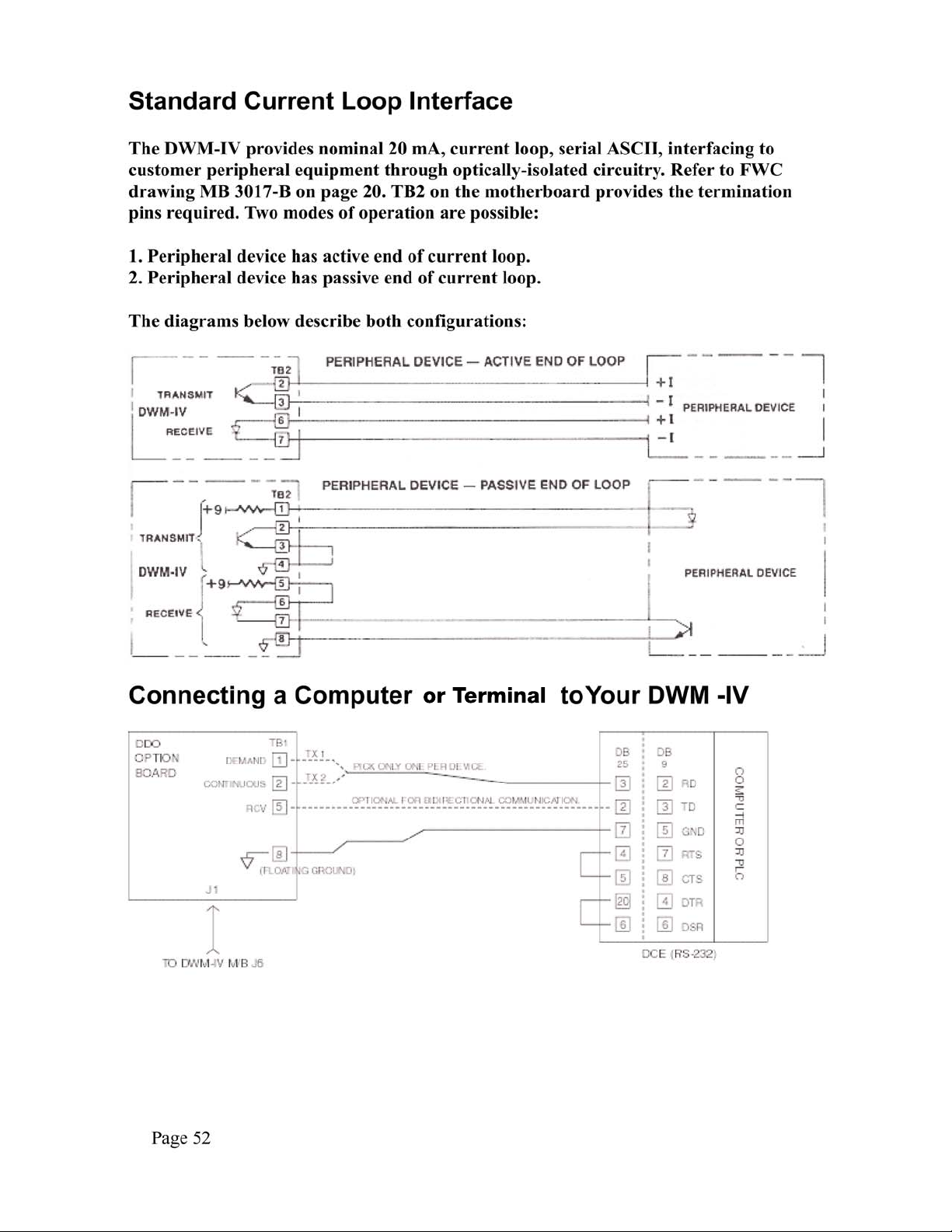
Remote Control Inputs
The functions of ZERO, TARE, GROSS/NET, selection and PRINT may be
performed remotely via voltage-free contacts across the indicated pins on TB1 of the
DWM-IV motherboard and pins 5 or 6. ZERO, TARE, and PRINT inputs should
have a minimum duration of 500 milliseconds while the GROSS/NET input must be
maintained closed for net and open for gross.
Data Output Formats
The DWM-IV data output is selectable using the Set-up procedure using F3.2, F3.4,
F3.5, F3.6, F3.8, F4.1, F4.5, F4.6, F4.7, F4.8, F6.0 as described in the manual. The
information sent can optionally include time/date, consecutive number and ID
number. Additionally, the output can be configured to send the data in any of eight
(8) different formats. The weight data may be configured in any of four (4) formats.
The time/date information may be selected from four (4) formats.
Whenever data is transmitted, the first character sent is always an ASCII STX (02h)
to signify the start of data block. The data previously selected
is sent and is always terminated by an ASCII ETX (03h). The Continuous Output
formats do not adhere to this convention, however. In addition to the characters
Page 43
Page 46
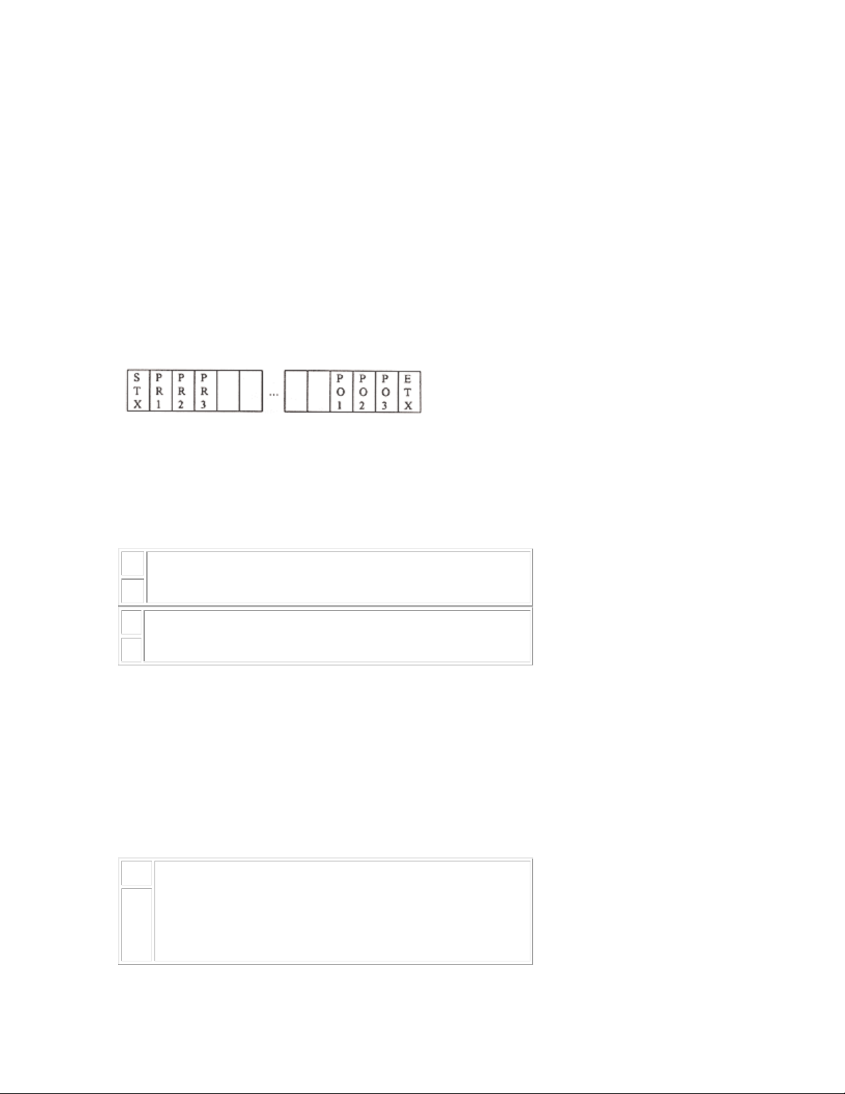
described, the user may program up to three (3) preamble characters that are sent
after the STX character and up to three (3) postamble characters which are
transmitted just before the ETX character. These characters may be used for
special purposes such as releasing the paper clamp on a ticket printer or performing
a double wide print out.
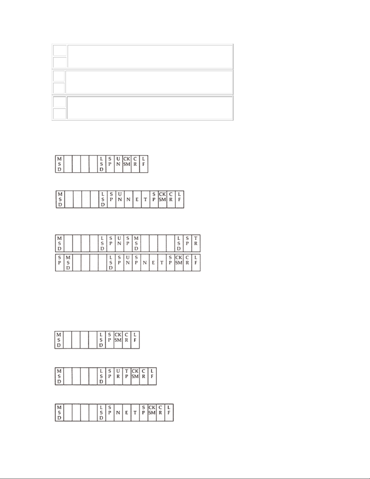
All Weight data fields are six (6) active characters in length. If required by the
programmed capacity, this field will be expanded to seven (7) characters to include
the decimal point (2Eh) justified in the proper position within the weight field. Nonsignificant leading zeroes will be transmitted as spaces but the least significant three
(3) characters are not zero suppressed.
Data Block Format:
Data Block
where PR is preamble and PO is postamble.
In the format descriptions below, the following abbreviations apply:
U
represents the programmed units and may be
from zero to seven characters long.
N
T
represents the tare and may be any of the following
depending on the programmed configuration:
R
1. TR If single register tare is used and tare was entered via pushbutton.
2. TR(K) If single register tare is used and tare was entered via the keyboard.
3. TRx If Ten-Tare Look-up is enabled. x represents the tare register currently
selected. Tare value was entered via the pushbutton.
4. TRx(K) Ten -Tare Look-up as in 3. above but entered via the keyboard.
Represents the checksum data which is the sum of the
CK
data previously sent and is in 2's complement binary
notation. The checksum is comprised of two ASCII
SM
hexadecimal characters. These two characters are only
inserted if the 'Checksum Transmit Enable' is enabled.
Page 44
Page 47
S
ASCII character space (20h).
P
C
ASCII character carriage return (0Dh).
R
L
ASCII character line feed (0Ah).
F
A. Displayed Weight Only
Gross wt Only
Net wt Only
B. Single Line GTN
Note: If tare equals zero or in the gross mode, the format is the same as in Displayed
Weight Only above.
C. Multiple Line GTN
Gross wt
Tare w t
Net wt
Page 45
Page 48

D. Status, Weight and Tare
Status Words Table
Bit STATUS A STATUS B STATUS C
8 7 0 0 Relay 8
4 6 Center Zero Print Key Relay 7
H
2 5 Motion Decimal pos Relay 6
1 4 Gross Decimal pos Relay 5
8 3 Negative Decimal pos Relay 4
4 2 Undercap Zero Incr Size Relay 3
L
2 1 Overcap Incr Size Relay 2
1 0 LB Incr Size Relay 1
Notes:
1. Conditions noted are true if corresponding bit is a logic 1.
2. Increment Size values correspond to the following table:
Bit 2 1 0
0 0 0 By 1's
0 0 1 By 2's
0 1 0 By 5's
0 1 1 By 10's
1 0 0 By 20's
1 0 1 By 50's
1 1 0 By 100's
3. Decimal Position values correspond to the following table:
Bit 5 4 3
0 0 0 No Decimal
0 0 1 Illegal
Page 46
0 1 0 XXXXX.X
Page 49

0 1 1 XXXX.XX
1 0 0 XXX.XXX
1 0 1 XX.XXXX
4. Print Key = 1 if front panel PRINT key is being pressed.
5. Relay = 1 if relay energized.
6. Each Status Word is comprised of two ASCII hex characters (0 - 9, A - F),
representing the two 4-bit patterns that make up each Status Word. Example: 5 1 in
the Status B position would be bit pattern 0101 0001 = count by .2 and print button
pressed.
E) Time/Date Format
12 Hour
Time Date
HH:MMASMM-DD-YYS
PS P
24 Hour
Time Date
HH:MMSMM-DD-YYS
PP
F) Totals Format
Where 'x' represents the totals register number currently selected. If checksum is
enabled, it is inserted before a CR-LF sequence.
G) ID Number
H) Consecutive Number
Page 47
Page 50

I) Z660 Scoreboard
J) ASCII - with Preamble and Postamble (No STX or ETX)
K) RD
Custom Print Format Programming
By selecting the custom print options, it is possible to design a print output to
conform to almost any given requirements.
Custom data sent via the PRINT function (either front panel button, remote input,
or external voltage free contact) is enabled by selecting the C option under F4.7,
Weight Print Format, of the SET-UP procedure. Similarly, custom totals data is
enabled via F4.8, Totals Print Format.
A total of eighty (80) print codes may be entered as a combination of weight print
codes and totals print codes. The codes are each one byte (8 bits) long. Any value
less than 128 is treated as a literal ASCII character and will print as such. Codes
greater than 127 are special print codes and the DWM-IV will interpret them
according to the chart below to perform the described action. The code 150 is in
essence a NO OPERATION code (print zero spaces) and may be used to reserve
space if later it is determined that codes must be inserted . In this way, not all of the
codes need be re-entered. Merely replace the 150 codes with the required ones. A
Page 48
Page 51

total of eighty (80) codes may be entered. It is possible to print out particular
headers or titles by using the ASCII representations for them in decimal.
Entering Print Codes
1. first enable under F4.7 and/or F4.8.
2. Under F3.8 of the SET-UP procedure, enter the preamble and postamble data, if
needed.
3. After the postamble step the weight data codes are entered. The display will show
the following:
xx.yyy
where xx is the code count and yyy is the print code in decimal. to enter a new
code, use the numeric keypad. Press [ENTER] to store the code and advance to the
next one. Press [ENTER] without pressing any numeric buttons to retain the
existing data. Terminate the codes with a value of 255 and [ENTER]. The display
will blink momentarily.
4. Enter the codes for the totals print-out using the same method described above
for the weight codes. Remember to always terminate the codes with value 255. Any
number greater than 255 will be ignored and the previous data will be re-displayed.
Print Codes and Descriptions
For the following table, refer to the Data Output Formats (referred to as D.O.F.)
and SET-UP procedure sections of this manual.
Code Descriptions
128
129
130
131
132
Inserts ASCII STX and up to three (3) bytes of preamble codes, as set in step F3.8
of set-up procedure.
Formats weight data as described in D.O.F. Type is selected in Step F4.5 of SET UP procedure.
Formats time and date data as programmed in Step F4.6 of SET-UP.
Formats the ID number entered using Function 7 from the front panel. Must be
enabled under F3.5.
Formats the consecutive number. Must be enabled under Step F3.4.
133
134
135
Formats the total or subtotal data and register number as described in D.O.F.
Prints the total register number currently selected (zero to nine).
Internal code for carriage return-line feed. Do not use.
Page 49
Page 52

136
Internal code for carriage return-line feed and checksum insertion if enabled. Do
not use.
137
138
139
140
141
142
143
144
145
146
147
148
Inserts the previously entered postamble entered under Step 3.8 of SET-UP
procedure.
Formats net weight data for a GTN-type print-out. If DWM-IV is in gross mode of
operation, this field is padded with spaces in place of the weight data.
Formats tare weight data for a GTN-type print. If in the gross mode, field is padded
with spaces.
Gross weight data for GTN print-out.
Formats according to ÔDisplayed Weight OnlyÕ as described in D.O.F. section of
this manual.
Formats the time data in twelve (12) or twenty-four (24) hour mode as pre-
programmed in Step F3.7.
Formats the Date data as month, day, and year.
Inserts the checksum data described in D.O.F.
Delay.
Store Preamble.
Format Tare.
Continuous Format.
149
150-
239
240-
254
Job: Date:
Step Code Comment Step Code Comment Step Code Comment
1 150 No Operation 24 10 47
2 40 ( 25 13 48
3 89 Y 26 130 Formats/Date 49
4 79 O 27 10 50
5 85 U 28 13 51
6 82 R 29 129 Formats Weigh Data 52
7 32 Space 30 10 53
8 78 N 31 13 54
End Buffer (NO ETX).
Specifies multiple spaces ;150=0 spaces ,151=1 space, 160=10 spaces etc.
Specifies multiple carriage returns as above.
Sample DWM-IV Custom Print Codes
Page 50
Page 53
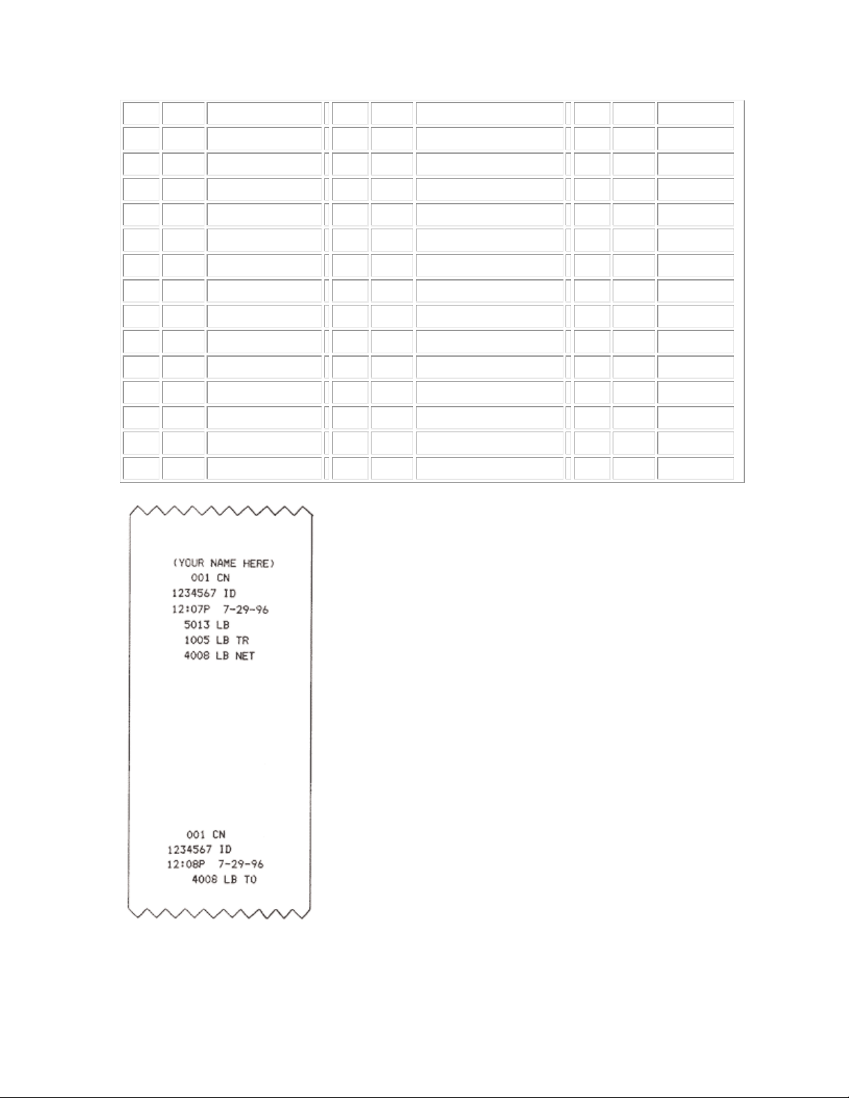
9 65 A 32 255 Ends Print Field 55
10 77 M 33 132 56
11 69 E 34 10 57
12 32 35 13 58
13 72 H 36 131 59
14 69 E 37 10 60
15 82 R 38 13 61
16 69 E 39 130 62
17 41 ) 40 10 63
18 10 Line Feed 41 13 64
19 13 Carriage Return 42 133 Formats Totals 65
20 132 Formats CN 43 10 66
21 10 44 13 67
22 13 45 255 Ends Total Field 68
23 131 Formats ID 46 69
Page 51
Page 54
Page 55

Page 53
Page 56

Page 54
Page 57

Page 55
Page 58

Page 59

Page 60
VT 11 00001011 013 0B K 75 01001011 113 4B TA11
FF 12 00001100 014 0C L 76 01001100 114 4C TA12
CR 13 00001101 015 0D M 77 01001101 115 4D TA13
SO 14 00001110 016 0E N 78 01001110 116 4E TA14
SI 15 00001111 017 0F O 79 01001111 117 4F TA15
DLE 16 00010000 020 10 P 80 01010000 120 50 TA16
DC1 17 00010001 021 11 LLO Q 81 01010001 121 51 TA17
DC2 18 00010010 022 12 R 82 01010010 122 52 TA18
DC3 19 00010011 023 13 S 83 01010011 123 53 TA19
DC4 20 00010100 024 14 DCL T 84 01010100 124 54 TA20
NAK 21 00010101 025 15 PPU U 85 01010101 125 55 TA21
SYNC 22 00010110 026 16 V 86 01010110 126 56 TA22
ETB 23 00010111 027 17 W 87 01010111 127 57 TA23
CAN 24 00011000 030 18 SPE X 88 01011000 130 58 TA24
EM 25 00011001 031 19 SPD Y 89 01011001 131 59 TA25
SUB 26 00011010 032 1A Z 90 01011010 132 5A TA26
ESC 27 00011011 033 1B [ 91 01011011 133 5B TA27
FS 28 00011100 034 1C \ 92 01011100 134 5C TA28
GS 29 00011101 035 1D ] 93 01011101 135 5D TA29
RS 30 00011110 036 1E ^ 94 01011110 136 5E TA30
US 31 00011111 037 1F _ 95 0101111 1 137 5F UNT
space 32 00100000 040 20 LA0 ` 96 01100000 140 60 SC0
! 33 00100001 041 21 LA1 a 97 01100001 141 61 SC1
" 34 00100010 042 22 LA2 b 98 01100010 142 62 SC2
# 35 00100011 043 23 LA3 c 99 01100011 143 63 SC3
$ 36 00100100 044 24 LA4 d 100 01100100 144 64 SC4
% 37 00100101 045 25 LA5 e 101 01100101 145 65 SC5
& 38 00100110 046 26 LA6 f 102 01100110 146 66 SC6
' 39 00100111 047 27 LA7 g 103 01100111 147 67 SC7
( 40 00101000 050 28 LA8 h 104 01101000 150 68 SC8
) 41 00101001 051 29 LA9 i 105 01101001 151 69 SC9
* 42 00101010 052 2A LA10 j 106 01101010 152 6A SC10
+ 43 00101011 053 2B LA11 k 107 01101011 153 6B SC11
, 44 00101100 054 2C LA12 l 108 01101100 154 6C SC12
- 45 00101101 055 2D LA13 m 109 01101101 155 6D SC13
Page 58
Page 61
. 46 00101110 056 2E LA14 n 110 01101110 156 6E SC14
/ 47 00101111 057 2F LA15 o 111 01101111 157 6F SC15
0 48 00110000 060 30 LA16 p 112 01110000 160 70 SC16
1 49 00110001 061 31 LA17 q 113 01110001 161 71 SC17
2 50 00110010 062 32 LA18 r 114 01110010 162 72 SC18
3 51 00110011 063 33 LA19 s 115 01110011 163 73 SC19
4 52 00110100 064 34 LA20 t 116 01110100 164 74 SC20
5 53 00110101 065 35 LA21 u 117 01110101 165 75 SC21
6 54 00110110 066 36 LA22 v 118 01110111 166 76 SC22
7 55 00110111 067 37 LA23 w 119 01110000 167 77 SC23
8 56 00111000 070 38 LA24 x 120 01111000 170 78 SC24
9 57 00111001 071 39 LA25 y 121 01111001 171 79 SC25
: 58 00111010 072 3A LA26 z 122 01111010 172 7A SC26
; 59 00111011 073 3B LA27 { 123 01111011 173 7B SC27
< 60 00111100 074 3C LA28 | 124 01111100 174 7C SC28
= 61 00111101 075 3D LA29 } 125 01111101 175 7D SC29
> 62 00111110 076 3E LA30 ~ 126 01111110 176 7E SC30
? 63 00111111 077 3F UNL DEL 127 01111111 177 7F SC31
Page 59
Page 62

DWM-IV Limited Warranty
Rice Lake Weighing Systems (RLWS) warrants that all RLWS equipment and systems properly installed by a
Distributor or Original Equipment Manufacturer (OEM) will operate per written specifications as confirmed by
the Distributor/OEM and accepted by RLWS. All systems and components are warranted against defects in
materials and workmanship for one (1) year.
RLWS warrants that the equipment sold hereunder will conform to the current written specifications authorized
by RLWS. RLWS warrants the equipment against faulty workmanship and defective materials. If any equipment
fails to conform to these warranties, RLWS will, at its option, repair or replace such goods returned within the
warranty period subject to the following conditions:
• Upon discovery by Buyer of such nonconformity, RLWS will be given prompt written notice with a
detailed explanation of the alleged deficiencies.
• Individual electronic components returned to RLWS for warranty purposes must be packaged to
prevent electrostatic discharge (ESD) damage in shipment. Packaging requirements are listed in a
publication, Protecting Your Components From Static Damage in Shipment, available from RLWS
Equipment Return Department.
• Examination of such equipment by RLWS confirms that the nonconformity actually exists, and was
not caused by accident, misuse, neglect, alteration, improper installation, improper repair or
improper testing; RLWS shall be the sole judge of all alleged non-conformities.
• Such equipment has not been modified, altered, or changed by any person other than RLWS or its
duly authorized repair agents.
• RLWS will have a reasonable time to repair or replace the defective equipment. Buyer is responsible
for shipping charges both ways.
• In no event will RLWS be responsible for travel time or on-location repairs, including assembly or
disassembly of equipment, nor will RLWS be liable for the cost of any repairs made by others.
THESE WARRANTIES EXCLUDE ALL OTHER WARRANTIES, EXPRESSED OR IMPLIED, INCLUDING WITHOUT
LIMITATION WARRANTIES OF MERCHANTABILITY OR FITNESS FOR A PARTICULAR PURPOSE. NEITHER
RLWS
RLWS AND BUYER AGREE THAT RLWS’S SOLE AND EXCLUSIVE LIABILITY HEREUNDER IS LIMITED TO
REPAIR OR REPLACEMENT OF SUCH GOODS. IN ACCEPTING THIS WARRANTY, THE BUYER WAIVES ANY AND
ALL OTHER CLAIMS TO WARRANTY.
SHOULD THE SELLER BE OTHER THAN RLWS, THE BUYER AGREES TO LOOK ONLY TO THE SELLER FOR
WARRANTY CLAIMS.
NO TERMS, CONDITIONS, UNDERSTANDING, OR AGREEMENTS PURPORTING TO MODIFY THE TERMS OF THIS
WARRANTY SHALL HAVE ANY LEGAL EFFECT UNLESS MADE IN WRITING AND SIGNED BY A CORPORATE
OFFICER OF RLWS AND THE BUYER.
NOR DISTRIBUTOR WILL, IN ANY EVENT, BE LIABLE FOR INCIDENTAL OR CONSEQUENTIAL DAMAGES.
© 2009 Rice Lake Weighing Systems, Inc. Rice Lake, WI USA. All Rights Reserved.
RICE LAKE WEIGHING SYSTEMS • 230 WEST COLEMAN STREET • RICE LAKE, WISCONSIN 54868 • USA
 Loading...