

Page 1
Digital Diagnostic Junction Box
Version 1.4
Installation Manual
77224
Page 2

Contents
About This Manual ................................................................................................................................... 1
1.0 Introduction.................................................................................................................................. 1
1.1 System Configurations and Options. . . . . . . . . . . . . . . . . . . . . . . . . . . . . . . . . . . . . . . . . . . . . . . . . . 2
2.0 Installation ................................................................................................................................... 3
2.1 Unpacking and Assembly . . . . . . . . . . . . . . . . . . . . . . . . . . . . . . . . . . . . . . . . . . . . . . . . . . . . . . . . . 3
2.2 Mounting the Enclosure . . . . . . . . . . . . . . . . . . . . . . . . . . . . . . . . . . . . . . . . . . . . . . . . . . . . . . . . . . . 3
2.3 Cable Connections . . . . . . . . . . . . . . . . . . . . . . . . . . . . . . . . . . . . . . . . . . . . . . . . . . . . . . . . . . . . . . 3
2.4 Load Cells . . . . . . . . . . . . . . . . . . . . . . . . . . . . . . . . . . . . . . . . . . . . . . . . . . . . . . . . . . . . . . . . . . . . . 3
2.5 Serial Communications . . . . . . . . . . . . . . . . . . . . . . . . . . . . . . . . . . . . . . . . . . . . . . . . . . . . . . . . . . . 5
2.6 Primary/Secondary Configuration . . . . . . . . . . . . . . . . . . . . . . . . . . . . . . . . . . . . . . . . . . . . . . . . . . . 5
2.7 Digital I/O. . . . . . . . . . . . . . . . . . . . . . . . . . . . . . . . . . . . . . . . . . . . . . . . . . . . . . . . . . . . . . . . . . . . . . 8
2.8 Analog Output . . . . . . . . . . . . . . . . . . . . . . . . . . . . . . . . . . . . . . . . . . . . . . . . . . . . . . . . . . . . . . . . . . 9
2.9 Core Module DIP Switches . . . . . . . . . . . . . . . . . . . . . . . . . . . . . . . . . . . . . . . . . . . . . . . . . . . . . . . 10
2.10 Core Module Reset Procedure . . . . . . . . . . . . . . . . . . . . . . . . . . . . . . . . . . . . . . . . . . . . . . . . . . . . 10
2.11 iQUBE Communications Configurations . . . . . . . . . . . . . . . . . . . . . . . . . . . . . . . . . . . . . . . . . . . . . 11
2.11.1 Copper-Wire Connection to the 920i. . . . . . . . . . . . . . . . . . . . . . . . . . . . . . . . . . . . . . . . . . . . . . . . . . 11
2.11.2 Fiber-Optic and Ethernet Communications . . . . . . . . . . . . . . . . . . . . . . . . . . . . . . . . . . . . . . . . . . . . . 11
2.11.3 Remote Fiber-Optic Module (PN 77789) . . . . . . . . . . . . . . . . . . . . . . . . . . . . . . . . . . . . . . . . . . . . . . . 12
2.11.4 Analog Output . . . . . . . . . . . . . . . . . . . . . . . . . . . . . . . . . . . . . . . . . . . . . . . . . . . . . . . . . . . . . . . . . . 13
2.12 Installing Tap and Run Connectors for 920i Power . . . . . . . . . . . . . . . . . . . . . . . . . . . . . . . . . . . . . 14
2.13 Installing the Optional Power Supply . . . . . . . . . . . . . . . . . . . . . . . . . . . . . . . . . . . . . . . . . . . . . . . 15
2.14 Installing Option Cards . . . . . . . . . . . . . . . . . . . . . . . . . . . . . . . . . . . . . . . . . . . . . . . . . . . . . . . . . . 15
2.14.1 Digital-to-Analog (DAC) Conversion Cards . . . . . . . . . . . . . . . . . . . . . . . . . . . . . . . . . . . . . . . . . . . . . 15
2.14.2 iQUBE Internal Fiber-Optic Option. . . . . . . . . . . . . . . . . . . . . . . . . . . . . . . . . . . . . . . . . . . . . . . . . . . . 15
2.14.3 iQUBE Internal Ethernet Option. . . . . . . . . . . . . . . . . . . . . . . . . . . . . . . . . . . . . . . . . . . . . . . . . . . . . . 15
2.14.4 920i Internal Fiber-Optic Option . . . . . . . . . . . . . . . . . . . . . . . . . . . . . . . . . . . . . . . . . . . . . . . . . . . . . 16
2.15 Fuse Replacement . . . . . . . . . . . . . . . . . . . . . . . . . . . . . . . . . . . . . . . . . . . . . . . . . . . . . . . . . . . . . 16
2.16 Parts Kit Contents . . . . . . . . . . . . . . . . . . . . . . . . . . . . . . . . . . . . . . . . . . . . . . . . . . . . . . . . . . . . . 16
2.17 Replacement Parts and Assembly Drawings . . . . . . . . . . . . . . . . . . . . . . . . . . . . . . . . . . . . . . . . . 17
3.0 920i Indicator Configuration...................................................................................................... 20
3.1 Configuration Methods . . . . . . . . . . . . . . . . . . . . . . . . . . . . . . . . . . . . . . . . . . . . . . . . . . . . . . . . . . 20
3.2 920i–iQUBE Menu Configuration . . . . . . . . . . . . . . . . . . . . . . . . . . . . . . . . . . . . . . . . . . . . . . . . . . . 20
3.3 Configuration and Calibration Summary. . . . . . . . . . . . . . . . . . . . . . . . . . . . . . . . . . . . . . . . . . . . . . 21
3.4 iQUBE-Specific Menu Structures and Parameter Descriptions . . . . . . . . . . . . . . . . . . . . . . . . . . . . . 22
3.4.1 SERIAL Menu, iQUBE Submenu. . . . . . . . . . . . . . . . . . . . . . . . . . . . . . . . . . . . . . . . . . . . . . . . . . . . . 22
3.4.2 iQUBE Submenu, IQDIAG Parameters . . . . . . . . . . . . . . . . . . . . . . . . . . . . . . . . . . . . . . . . . . . . . . . . 25
3.4.3 PFORMT Menu. . . . . . . . . . . . . . . . . . . . . . . . . . . . . . . . . . . . . . . . . . . . . . . . . . . . . . . . . . . . . . . . . . 28
4.0 PC Configuration ........................................................................................................................ 29
4.1 Using Revolution III . . . . . . . . . . . . . . . . . . . . . . . . . . . . . . . . . . . . . . . . . . . . . . . . . . . . . . . . . . . . . 29
4.1.1 Revolution III Configuration . . . . . . . . . . . . . . . . . . . . . . . . . . . . . . . . . . . . . . . . . . . . . . . . . . . . . . . . . 29
4.1.2 Downloading to the iQUBE . . . . . . . . . . . . . . . . . . . . . . . . . . . . . . . . . . . . . . . . . . . . . . . . . . . . . . . . . 30
4.2 Using iRev . . . . . . . . . . . . . . . . . . . . . . . . . . . . . . . . . . . . . . . . . . . . . . . . . . . . . . . . . . . . . . . . . . . . 30
Technical training seminars are available through Rice Lake Weighing Systems.
Course descriptions and dates can be viewed at www.rlws.com or obtained
by calling 715-234-9171 and asking for the training department
© 2006 Rice Lake Weighing Systems. All rights reserved. Printed in the United States of America.
Specifications subject to change without notice.
March 2006
Page 3

5.0 Calibration ................................................................................................................................. 31
5.1 920i Front Panel Calibration. . . . . . . . . . . . . . . . . . . . . . . . . . . . . . . . . . . . . . . . . . . . . . . . . . . . . . . 31
5.1.1 Theoretical Calibration . . . . . . . . . . . . . . . . . . . . . . . . . . . . . . . . . . . . . . . . . . . . . . . . . . . . . . . . . . . . 31
5.1.2 Cal-Match Calibration . . . . . . . . . . . . . . . . . . . . . . . . . . . . . . . . . . . . . . . . . . . . . . . . . . . . . . . . . . . . . 31
5.1.3 Manual Trim Factor Adjustment (Tweaking). . . . . . . . . . . . . . . . . . . . . . . . . . . . . . . . . . . . . . . . . . . . . 32
5.1.4 Final Calibration . . . . . . . . . . . . . . . . . . . . . . . . . . . . . . . . . . . . . . . . . . . . . . . . . . . . . . . . . . . . . . . . . 32
5.2 Revolution III Calibration. . . . . . . . . . . . . . . . . . . . . . . . . . . . . . . . . . . . . . . . . . . . . . . . . . . . . . . . . . 32
6.0 Diagnostics ................................................................................................................................ 34
6.1 iQUBE Diagnostic . . . . . . . . . . . . . . . . . . . . . . . . . . . . . . . . . . . . . . . . . . . . . . . . . . . . . . . . . . . . . . 34
6.2 Cell Mate Relationships . . . . . . . . . . . . . . . . . . . . . . . . . . . . . . . . . . . . . . . . . . . . . . . . . . . . . . . . . . 34
6.3 Diagnostic Tests . . . . . . . . . . . . . . . . . . . . . . . . . . . . . . . . . . . . . . . . . . . . . . . . . . . . . . . . . . . . . . . 34
6.4 Diagnostic Setup . . . . . . . . . . . . . . . . . . . . . . . . . . . . . . . . . . . . . . . . . . . . . . . . . . . . . . . . . . . . . . . 36
6.4.1 Configuring the 920i Diagnostics Softkey . . . . . . . . . . . . . . . . . . . . . . . . . . . . . . . . . . . . . . . . . . . . . . 36
6.4.2 920i Diagnostic Display. . . . . . . . . . . . . . . . . . . . . . . . . . . . . . . . . . . . . . . . . . . . . . . . . . . . . . . . . . . . 36
6.5 Error Messages . . . . . . . . . . . . . . . . . . . . . . . . . . . . . . . . . . . . . . . . . . . . . . . . . . . . . . . . . . . . . . . . 36
7.0 Alerts.......................................................................................................................................... 38
7.1 Network Alert Notification . . . . . . . . . . . . . . . . . . . . . . . . . . . . . . . . . . . . . . . . . . . . . . . . . . . . . . . . 38
7.2 Alert Format. . . . . . . . . . . . . . . . . . . . . . . . . . . . . . . . . . . . . . . . . . . . . . . . . . . . . . . . . . . . . . . . . . . 39
7.3 FEATURE Menu, CONTACT Submenu . . . . . . . . . . . . . . . . . . . . . . . . . . . . . . . . . . . . . . . . . . . . . . 40
7.4 PFORMT Menu . . . . . . . . . . . . . . . . . . . . . . . . . . . . . . . . . . . . . . . . . . . . . . . . . . . . . . . . . . . . . . . . 41
8.0 920i Serial Commands .............................................................................................................. 42
9.0 Appendix .................................................................................................................................... 45
9.1 Troubleshooting. . . . . . . . . . . . . . . . . . . . . . . . . . . . . . . . . . . . . . . . . . . . . . . . . . . . . . . . . . . . . . . . 45
9.1.1 General Steps. . . . . . . . . . . . . . . . . . . . . . . . . . . . . . . . . . . . . . . . . . . . . . . . . . . . . . . . . . . . . . . . . . . 45
9.1.2 Technical Assistance Guide and Questionnaire . . . . . . . . . . . . . . . . . . . . . . . . . . . . . . . . . . . . . . . . . . 46
9.2 Printed Information . . . . . . . . . . . . . . . . . . . . . . . . . . . . . . . . . . . . . . . . . . . . . . . . . . . . . . . . . . . . . 48
9.3 Flash Update Procedure . . . . . . . . . . . . . . . . . . . . . . . . . . . . . . . . . . . . . . . . . . . . . . . . . . . . . . . . . 49
9.4 Software Version Updates . . . . . . . . . . . . . . . . . . . . . . . . . . . . . . . . . . . . . . . . . . . . . . . . . . . . . . . . 50
9.5 Specifications . . . . . . . . . . . . . . . . . . . . . . . . . . . . . . . . . . . . . . . . . . . . . . . . . . . . . . . . . . . . . . . . . 50
iQUBE Limited Warranty......................................................................................................................... 51
ii iQUBE Installation Manual
Page 4

About This Manual
This manual is intended for use by service technicians
™
920i
responsible for installing and servicing
digital
diagnostic junction boxes. This manual applies to
Version 2145 or later of the
Version 2.05 or later of the
Configuration and calibration of the
accomplished using the
iQUBE software and
920i indicator software.
iQUBE can be
Revolution III configuration
utility.
For installations using the
can be configured using the
920i indicator, the indicator
Revolution III or iRev
™
configuration utilities, serial commands, or the 920i
indicator front panel keys.
1.0 Introduction
The iQUBE is a digital programmable junction box
used to connect up to 16 full bridge analog load cells.
iQUBE outputs a serial stream that can be directly
The
input to the
Ethernet cabling. Alternatively, the
configured to provide an analog output signal for
input to standard digital weight indicators.
The
iQUBE is available in three models:
• Four-channel
• Eight-channel
• Eight-channel with eight digital I/O channels
The basic
•The connector board provides the physical
•The core module, which plugs into the
Up to four
as a multidrop RS-485 network, consisting of one
primary and up to three secondary
maximum number of load cells supported for the
indicator is 16. Up to four individual weighing
platforms can be configured for a scale system.
The
iQUBE can be configured and calibrated through
920i indicator (Version 2.05 or later), the 920i’s
the
iRev configuration utility, or by using the iQUBE
module of the Revolution III configuration utility.
920i indicator using copper, fiber-optic, or
iQUBE can be
iQUBE consists of two boards:
connections for the load cells, serial
communications, analog output, and digital
I/O.
connector board, contains the
iQUBE’s
processor and stores configuration and
calibration data for the
iQUBE. The core
module provides a discrete A/D for each
channel input and converts the analog load
cell signal to a digital serial output.
iQUBE units can connect and commun ic ate
iQUBE units. The
920i
Some procedures described in this manual
require work inside the
enclosure. These procedures are to be
performed by qualified service personnel
only.
iQUBE or indicator
Authorized distributors and their employees
can view or download this manual from the
Rice Lake Weighing Systems distributor
www.rlws.com.
site at
iQUBE Options
Options for the iQUBE include the following;
Internal power supply: The 6 VDC power supply
mounts inside the
iQUBE enclosure and requires a
115/230 VAC input. This option is required for
applications that do not use the
920i applications that use more than two iQUBE units,
the distance between the
920i and the master iQUBE is
920i indicator and for
more than 75 feet, or the fiber optic modules are used.
Analog output: This option consists of a DAC card
that mounts on the core module and converts the
iQUBE’s digital output stream to 0–30 mV or 0–20
mA (passive only).
Fiber-optic transceiver: This option mounts on the
connector board to convert the
iQUBE’s serial output
into visible light for fiber-optic interface. When used
with the optional power supply, the fiber-optic
interface provides electrical isolation of the
iQUBE
from the host.
Fiber-optic transceiver to analog output: This
option converts digital fiber-optic data received from
the
iQUBE to an analog signal that can be input to the
load cell input of a standard weight indicator.
Ethernet: This option mounts on the connector board
to transfer the
Configuration
iQUBE’ s serial output onto the Ethernet.
There are two methods for configuration, using either
920i indicator as the host (menu or iRev
the
configuration) or by using the Revolution III utility to
configure the
the load cells connected to
iQUBE directly. Each method defines
iQUBE, which load cells
comprise a platform, and which platforms make up
the scale system.
Introduction 1
Page 5
Configuration consists of the following steps:
Define Load Cells: This is the electrical sensitivity
(mV/V output) and capacity specification of the load
cells. Load cell names and serial number can also be
specified.
Define Platforms: A platform is a contiguous weigh
bridge. Any
iQUBE board can assign load cells to two
separate platforms. A maximum of four platforms can
be defined in an
iQUBE system. The relationship
between load cells is also defined as a paired or
circular arrangement.
Define Systems: The platforms can be assigned to a
system. Up to four unique systems can be defined,
however the
920i will only support one system per
serial channel.
Error conditions generate a displayed error message if
connected to the
920i which, with an Ethernet card,
can be configured to e-mail the alert message to an
address. In addition, there is a visual LED indication
on the connector board to identify any load cell that
appears to have an abnormal condition.
Cell Emulation
Cell emulation allows the output of a failed load cell
to be emulated. Automatic or manual cell emulation
can be specified (limited to one cell per scale system),
using either truck scale (Type 1) or tank/hopper/floor
scale (Type 2) emulation algorithms.
NOTE: Satisfactory results from cell emulation require the
load to be centered and the scale installation to be plumb and
level.
Load Cell Trimming and Calibration
Cal-Match™ calibration calculates the load cell trim
based on a comparison of the signal generated by an
applied weight for each load cell to the signal
generated by all other load cells. If a known test
weight value is used, this calibration also sets the span
for the scale.
Three types of Cal-Match calibration can be
performed using the
iQUBE. Each type of calibration
captures the initial dead load of the scale and provides
a means to trim the outputs of the load cells.
Cal-Match Theoretical calibration allows each cell
to be zeroed and trim factors calculated. Based on the
cell capacity and sensitivity, the
iQUBE calculates
weight values based on the total signal from all of the
cells.
Cal-Match Section calibration requires a weight to
be placed over each section. Trimming can be
performed by running a weight cart down the middle
of the platform, stopping for calibration of each
section.
Corner calibration requires weight to be placed over
each cell individually. Corner trimming can be
performed for platforms using an even or odd number
of cells.
Diagnostics (Error 2)
Diagnostic functionality can be enabled for the iQUBE
to identify abnormal load cell outputs. This is based
on the reference established through cell associations.
The diagnostic conditions that can be identified for
paired configurations are open bridge or channel, zero
reference tolerance, drifting, peak-to-peak noise, and
out-of-balance conditions. Diagnostic conditions
recognized for circular configurations are limited to
open bridge or channel, drifting, and peak-to-peak
noise.
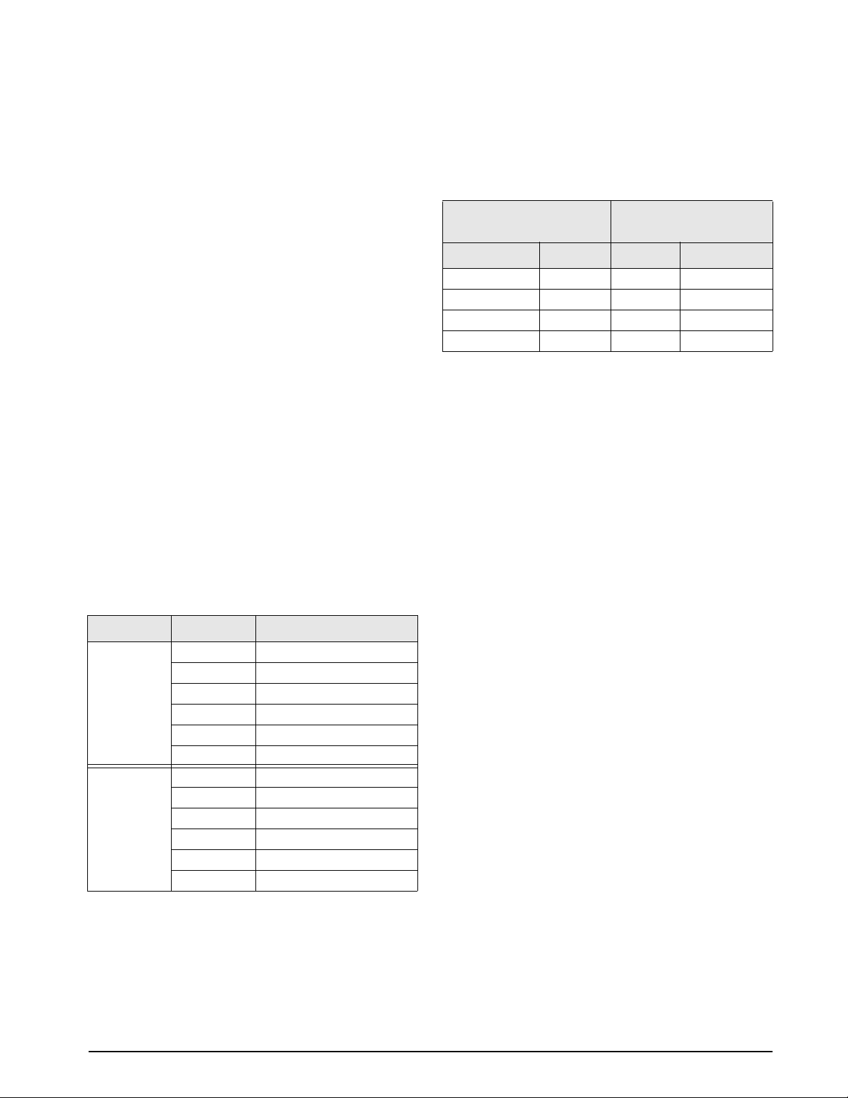
1.1 System Configurations and Options
Table 1-1 lists iQUBE model and option part numbers.
920i part numbers listed are for models without A/D
cards.
Model / Option PN
4-channel iQUBE
8-channel
8-channel
iQUBE internal power supply, 6 VDC
iQUBE internal Ethernet interface
iQUBE internal fiber-optic interface
920i internal fiber-optic interface
920i internal Ethernet communications card
920i Serial option card
Remote (external) fiber-optic interface 77789
Analog output, 0–30 mV 77146
Analog output, 0–20 mA (passive) 77797
920i universal model, 115 VAC
920i universal model, 230 VAC
920i deep enclosure, wwithout A/D model,
115 VAC
920i deep enclosure, wwithout A/D model,
230 VAC
920i panel mount model, 115 VAC
920i panel mount model, 230 VAC
920i wall mount model, 115 VAC
920i wall mount model, 230 VAC
iQUBE
iQUBE with digital I/O
Table 1-1. iQUBE Model and Option Part Numbers
92391
92392
92393
77531
77142
77143
77788
71986
67604
77790
77791
93243
93244
77792
77793
77794
77795
2 iQUBE Installation Manual
Page 6
2.0 Installation
This section describes procedures for connecting load
cell, analog output, power, and serial communications
cables to the
drawings and replacement parts lists for the
are included for the service technician.
2.1 Unpacking and Assembly
Immediately after unpacking, visually inspect the
iQUBE to ensure all components are included and
undamaged. The shipping carton should contain the
iQUBE, this manual, and a parts kit. If any parts were
damaged in shipment, notify Rice Lake Weighing
Systems and the shipper immediately.
See Section 2.16 on page 16 for parts kit contents.
2.2 Mounting the Enclosure
The iQUBE can be mounted either vertically or
horizontally to a flat surface.
2.3 Cable Connections
All models of the iQUBE provide ten cord grips for
cabling into the unit, plus a dedicated cord grip for a
ground wire. Up to eight load cells can be cabled into
iQUBE; other cord grips allow cabling for serial
the
communications, analog output, digital I/O, and AC
power. Install plugs in all un us ed co rd grips to prev ent
moisture from entering the enclosure.
iQUBE junction box. Assembly
iQUBE
Use a wrist strap to ground yourself and
protect components from electrostatic
discharge (ESD) when working inside the
iQUBE enclosure.
Channels 1–4
iQUBE
Connector Cell Name
J12A1J16A5
J13A2J17A6
J14A3J18A7
J15A4J19A8
NOTE: For secondary
with B, C, or D.
Table 2-1. iQUBE Connector and Load Cell Names
iQUBE units, the A prefix is replaced
Channels 5–8
(8-channel units only)
iQUBE
Connector Cell Name
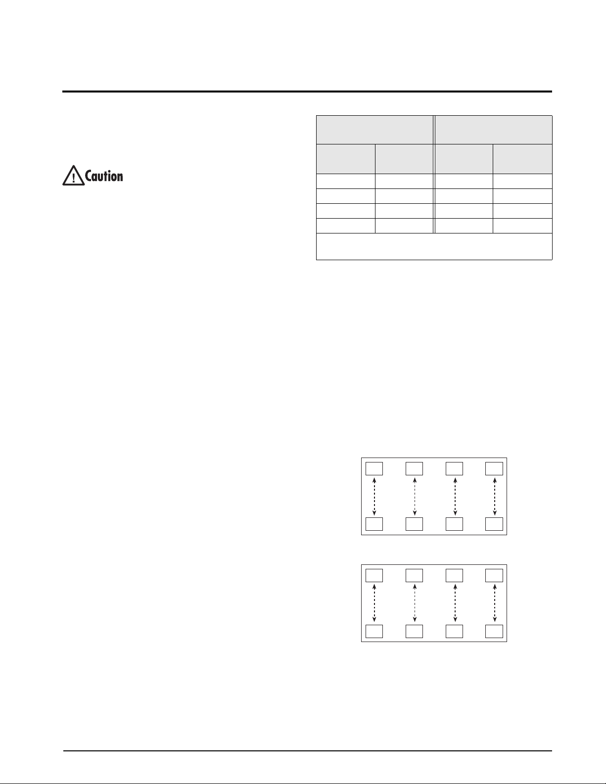
Figure 2-1 shows two exa mples of load cell naming
for eight-cell platforms. While load cells can be wired
to any connector on the
iQUBE connector board,
platforms defined as using “paired” sections
(including most truck scale applications) must
correctly associate these pairs to ensure valid
calibration and diagnostic functions.
In the top example of Figure 2-1, the even/odd load
cell wiring scheme requires cells A1/A2, A3/A4, A5/
A6, and A7/A8 to be associated as section pairs. In the
lower example, the sequential wiring requires pair
associations for A1/A8, A2/A7, A3/A6, and A4/A5.
Pair association is set in the platform configuration for
the scale.
A1
A3
A5
A7
2.4 Load Cells
When wiring load cells, cells wired to iQUBE
connectors J12–J19 (8-channel units) are assigned
default names A1–A8 (8-channel primary unit) or
B1–B8 (8-channel secondary unit). Be aware that
graphic representations of the weighing platform
shown when configuring the scale assume particular
locations for each load cell, based on the
connector used (see Table 2-1). Load cells can be
renamed during configuration.
iQUBE
A2
A4 A8
A6
A1 A2 A3 A4
A8 A7 A6 A5
Figure 2-1. Load Cell Pairing for Eight-Cell Platforms
Installation 3
Page 7
+SIG
1
–SIG
SHLD
JP1 is located on the back
side of the core module
1
+SIG
–SIG
+EXC
LOAD CELL 1
–EXC
J12
SHLD
1
+SIG
–SIG
+EXC
LOAD CELL 3
–EXC
J14
SHLD
1
+SIG
–SIG
+EXC
LOAD CELL 5
–EXC
J16
SHLD
1
+SIG
–SIG
+EXC
LOAD CELL 7
–EXC
J18
SHLD
INPUT/OUTPUT LEDs:
OUTPUT: GREEN = RELAY ON
INPUT: GREEN = SWITCH CLOSED
1
+SIG
–SIG
+EXC
LOAD CELL 2
–EXC
J13
SHLD
1
+SIG
–SIG
+EXC
LOAD CELL 4
–EXC
J15
SHLD
1
+SIG
–SIG
+EXC
LOAD CELL 6
–EXC
J17
SHLD
1
+SIG
–SIG
+EXC
LOAD CELL 8
–EXC
J19
SHLD
J21
IO 8
DAC
C44
C72
C47
C73
C50
C74
C53
C56
C76
C59
C62
C78
C65
8-CHANNEL
MODELS ONLY
IO 7
IO 6
IO 5
IO 4
DIGITAL I/O
ON
123 45678
DIP SWITCH / S1
4-Channel
C75
C77
8-Channel
C79
CORE MODULE
J8
ANALOG 2
1
+SIG
GND
+PWR
IO 3
IO 2
IO 1
1
J20
1
DIGITAL I/O
MODEL ONLY
J6
1
J4
Serial LEDs
JP1
D7
D5
D8
D6
1
EXPANSION MODULE
CELL STATUS LEDs
D1
C1 C2 C3 C4
C5 C6 C7 C8
Version
Label
J3
1
LED EXTENSION
SW1
SETUP
J2
J3
PIN 1
J9
ANALOG 1
SHLD
+SIG1–SIG
–SIG
SHLD
BOARD POWER
+PWR
OFF ON
F1
J10
1
GND SHLD
FIBER-OPTIC OR
GREEN =
POWER ON
J11
SECONDARY
POWER
1
GND SHLD
+PWR
ETHERNET
OPTION
J7
B
Y
Z/TXD A/RXD
GNDSHLD
1
GND SHLD
ZB
Y
1
A
J4
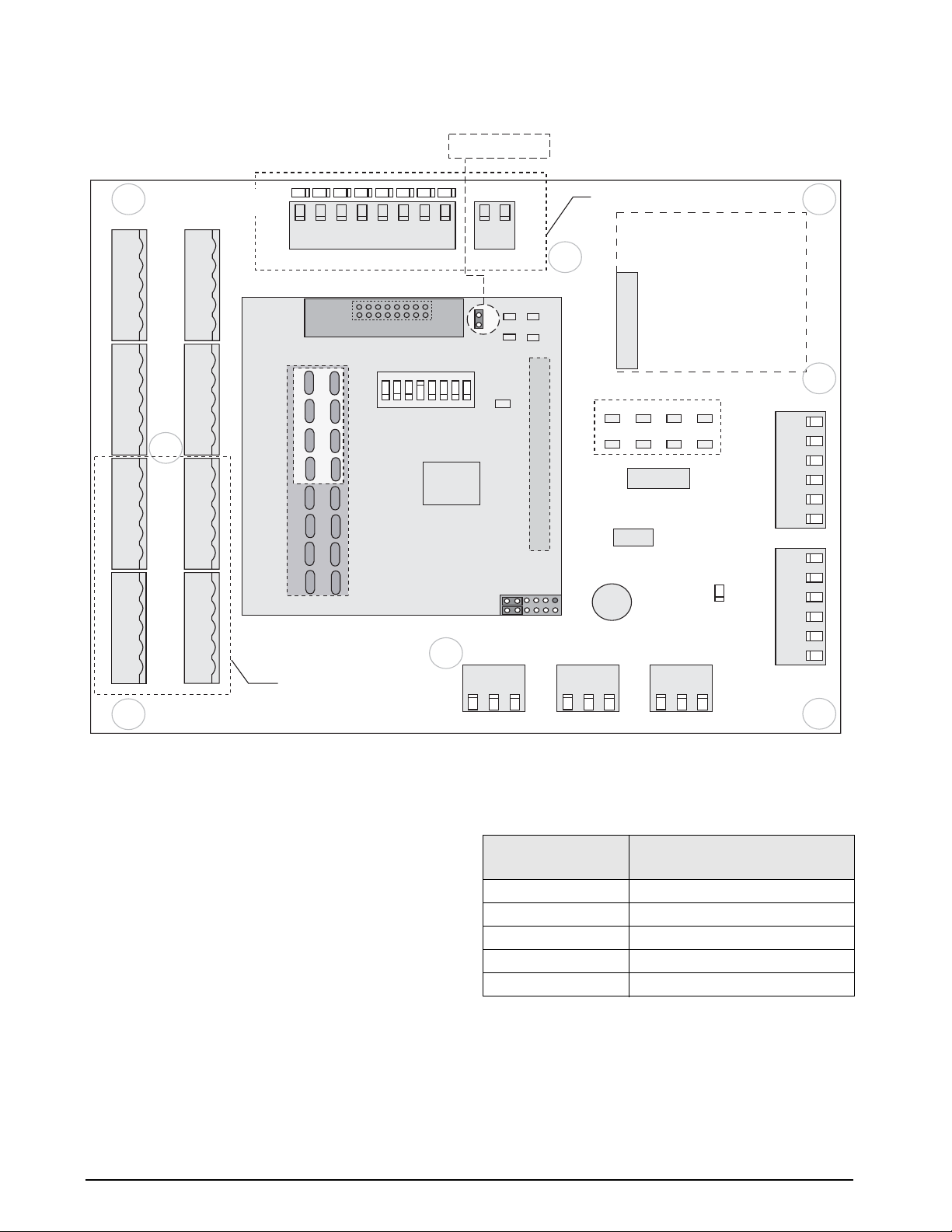
Figure 2-2. iQUBE Connector Board (8-channel with Digital I/O) with Core Module and DAC Card
Load Cell Wiring
T o attach load cell cables to the connector board, route
the cables through the cord grips on the load cell
connector end of the
iQUBE enclosure. Note the load
cell numbering assigned to the connectors (see
Figure 2-2).
Strip 1/4-inch of insulation from the ends of the load
cell wires. Use the cable clamp tool included in the
parts kit to open the connector springs and install
wires into the connectors. Wire load cell cables as
shown in Table 2-2.
When connections are complete, use cable ties and
mounts to secure the load cell cables to the inside of
the enclosure.
4 iQUBE Installation Manual
Load Cell Connector
Pins (J12–J19)
Function
1+SIG
2–SIG
3+EXC
4–EXC
5SHIELD
Table 2-2. Load Cell Connector Pin Assignments
Page 8
2.5 Serial Communications
The J4 and J7 serial communications ports on the
iQUBE connector board support communications
between the
PC) or other
• Port J7 supports full-duplex RS-232 or
NOTE: Four-wire RS-485 communications with
the
card in the indicator. See Table 2-4.
• Port J4 supports full-duplex RS-485
To attach serial communications cables, route the
cable through the cord grip and wire to the connector.
Use cable ties to secure serial cables to the inside of
the enclosure.
Table 2-3 sho ws the pin assignments for connectors
J4 and J7. See Section 2.6 for information about
wiring for secondary units.
Connector Pin Signal
J7
J4
iQUBE and a host device (indicator or
iQUBE units.
four-wire RS-485 communications between
the primary
iQUBE unit and a host device.
The communications protocol (RS-232 or
RS-485) and port used to communicate with
the host device are selected by setting DIP
switches on the core module (see Section 2.9
on page 10).
920i requires installation of the serial option
Port J7 is also used by secondary
iQUBE units
to connect to the master and secondary unit.
communication between the primary
iQUBE
unit and any secondary iQUBE, and between
successive secondary units (see Section 2.6).
1SHIELD
2GND
3 Z / RS-232 TxD
4Y
5B
6 A / RS-232 RxD
1 A (RS-485 +RxD)
2 B (RS-485 –RxD)
3 Y (RS-485 +TxD)
4 Z (RS-485 –TxD)
5GND
6SHIELD
Table 2-3. Serial Port Pin Assignments
RS-485 Connections to Host 920i
Table 2-4 shows the connections needed for RS-485
communications between a host
920i serial expansion card, PN 67604, must be
The
920i and the iQUBE.
installed in the indicator for 4-wire RS-485
communications with the
920i Serial Option Board
J2 Connector
RS-485 Signal Pin Pin RS-485 Signal
+RxD 1 4 +TxD (Y)
–RxD 2 3 –TxD (Z)
–TxD 3 5 –RxD (B)
+TxD 4 6 +RxD (A)
Table 2-4. RS-485 Connections for 920i Host
NOTE: RS-485 is only supported on Port A of the
iQUBE.
iQUBE
J7 Connector
2-channel expansion board.
Communications Cable Distance Limitations
The maximum cable lengths that can be used for
various communications types depend on a number of
factors. These include: output impedance of the
transmitter; electrical noise in the environment; cable
capacitance, gauge, termination, and shielding.
Given that these and other factors will affect the
maximum usable cable length, the following distances
can be used as a general guide for
iQUBE
communications cabling:
RS-232: 50 ft (15 m)
RS-485: 1000 ft (300 m) (Twised pair cable)
Fiber-optic: 500 ft (150 m)
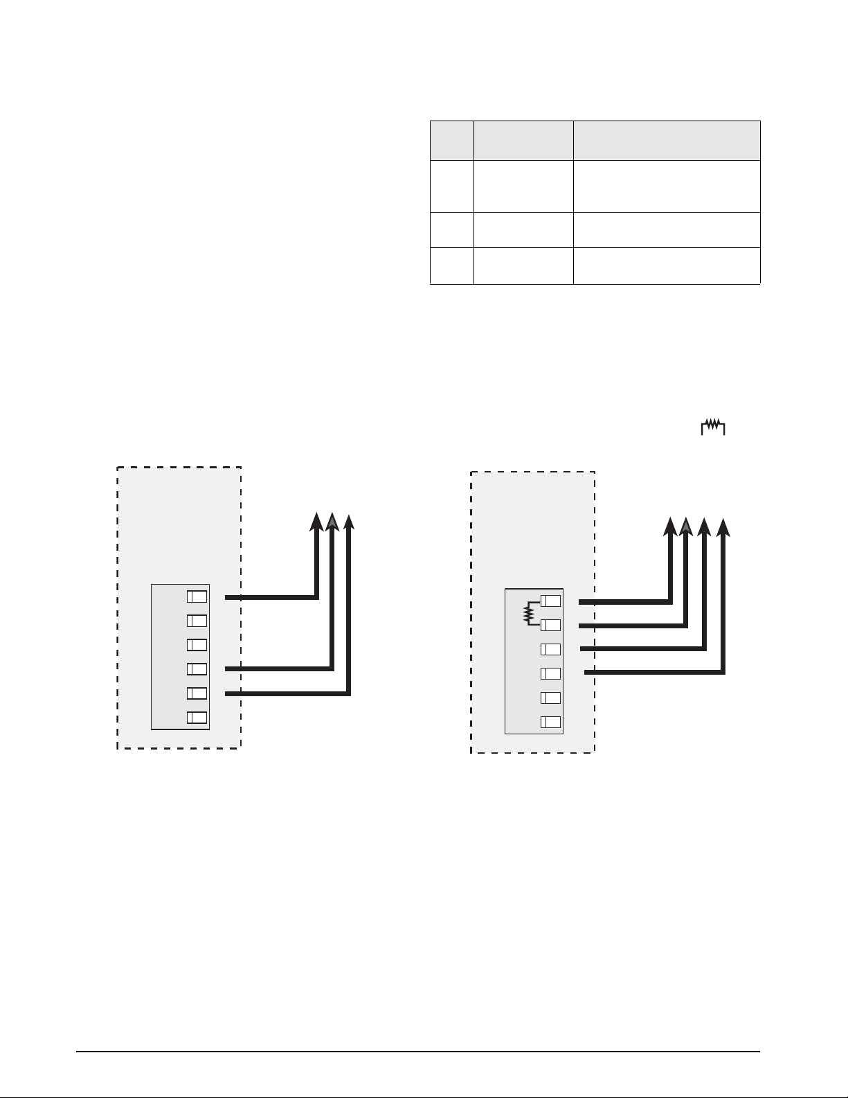
2.6 Primary/Secondary Configuration
Up to three iQUBE junction boxes can be configured
as secondary units controlled by a primary
unit. Figure 2-4 on page 7 shows the
primary-to-secondary wiring for multiple
units. Successive secondary units are wired in parallel
(A to A, B to B, and so on) as shown in Figure 2-5 .
NOTES:
•120Ω termination resistors (included in parts
kit) must be installed across the A and B
terminals on the J4 connector of the primary
unit and between the A and B terminals on the
J7 connector of the last secondary unit (see
Figure 2-4 on page 7).
• All six wires, including shield and ground
wires, must be connected between the
communicating
iQUBE units.
iQUBE
iQUBE
Installation 5
Page 9
DIP switches on the core module of each iQUBE must
be set to indicate whether the unit is a primary or
secondary, the communication protocol and port used,
and the secondary address.
• For the primary unit, DIP switches 1–3 must
all be set OFF. Set switches 5 and 6 based on
the protocol (RS-232 or RS-485) and port (J7
or J6) used to communicate with the host
device.
• For secondary units, DIP switch 5 must be set
ON; use switches 1–3 to set the secondary
address as shown in Table 2-5.
RS-232 to
Host PC (920i)
RS-232
DIP
Switch
1–3 OFF, OFF, OFF ON, OFF, OFF = SECONDARY1
5 RS-232 = OFF
6 OFF = J7
Primary Unit Secondary Unit
OFF, ON, OFF = SECONDARY2
ON, ON, OFF = SECONDARY3
ON
RS-485 = ON
iQUBE Port
ON = J6
Table 2-5. Core Module Communications DIP Switches
See Section 2.9 on page 10 for more information
about the core module DIP switches.
RS-485 to
920i Serial
120Ω
Option Board
RS-485
PRIMARY
iQUBE UNITiQUBE UNIT
J7
1
YBZ/TXD A/RXD
GNDSHLD
TXD
RXD
GND
Figure 2-3. 920i W iring
PRIMARY
iQUBE UNITiQUBE UNIT
J7
120Ω
1
YBZ/TXD A/RXD
GNDSHLD
A RS-485 TXD +
A RS-485 TXD -
A RS-485 RXD +
A RS-485 RXD -
6 iQUBE Installation Manual
Page 10
ALL SIX WIRES, INCLUDING SHIELD
AND GROUND WIRES, MUST BE
CONNECTED FOR COMMUNICATION
NOTE!
BETWEEN iQUBE UNITS
PRIMARY
iQUBE UNIT
J7
1
120Ω
1
J4
YBZ/TXD A/RXD
GNDSHLD
GND SHLD
ZB
Y
A
TO HOST
INDICATOR OR PC
SECONDARY1
iQUBE UNIT
J7
120Ω
YBZ/TXD A/RXD
GNDSHLD
1
GND SHLD
ZB
Y
1
A
J4
Figure 2-4. Primary-to-Secondary Communications Wiring
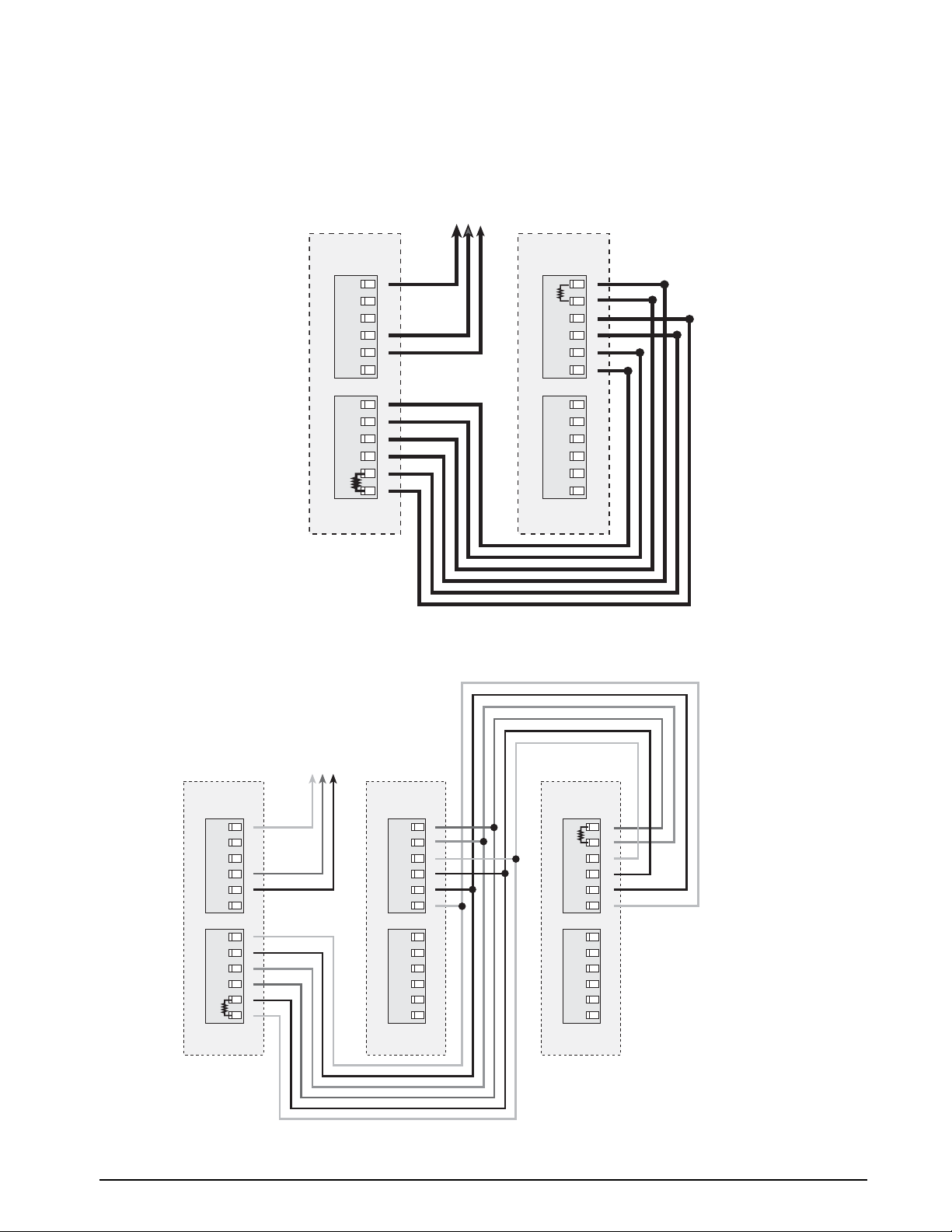
PRIMARY
iQUBE UNIT
J7
1
120Ω
1
J4
ALL SIX WIRES, INCLUDING SHIELD
AND GROUND WIRES, MUST BE
CONNECTED FOR COMMUNICATION
INDICATOR OR PC
NOTE!
BETWEEN iQUBE UNITS
TO HOST
SECONDARY1
iQUBE UNIT
SHLD
GNDZYBA
SECONDARYn
iQUBE UNIT
J7
YBZ/TXD A/RXD
GNDSHLD
GND SHLD
ZB
Y
A
YBZ/TXD A/RXD
GNDSHLD
1
GND SHLD
ZB
Y
A
1
1
1
J4
Figure 2-5. Primary-to-Multiple Secondary Communications
J7
120Ω
J4
YBZ/TXD A/RXD
GNDSHLD
GND SHLD
ZB
Y
A
Installation 7
Page 11

2.7 Digital I/O
The iQUBE junction box is available with support for eight channels of digital I/O.
Digital inputs can be set to provide many indicator functions, including all keypad functions. Digital inputs are
active low (0 VDC), inactive high (5 VDC).
Digital outputs are typically used to control relays that drive other equipment. Outputs are designed to sink,
rather than source, switching current.
Each output is a normally-open collector circuit, ca pable of sinking 25 mA when active. Digital outputs are wired
to switch relays when the digital output is active (low, 0 VDC) with reference to a 5 VDC supply. Auxiliary
power is available at connector J20 (see Figure 2-2 on page 4).
Table 2-6 shows the pin assignments for connector J21.
J21 Pin J21 Signal
1I/O 1
2I/O 2
3I/O 3
4I/O 4
5I/O 5
6I/O 6
7I/O 7
8I/O 8
Table 2-6. J21 Pin Assignments (Digital I/O)
Digital inputs and outputs for the
920i indicator are configured using the DIG I/O menu.
8 iQUBE Installation Manual
Page 12
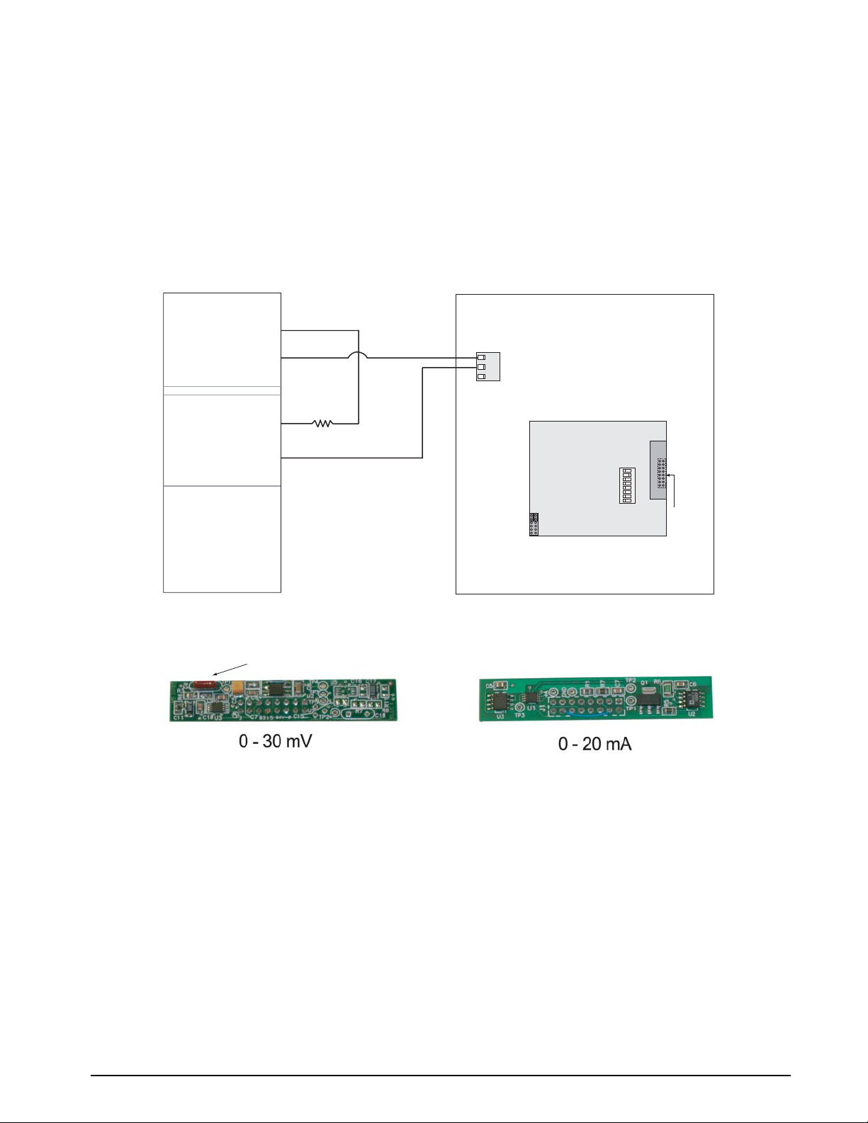
2.8 Analog Output
The analog output option consists of either a 0-30mV (PN 77146) or 0-20mA (PN 77797) digital-to-analog
(DAC) card that plugs into the
standard junction box, allowing connection to standard indicators. A 0–20 mA (passive only) DAC is also
available for PLC applications. the 0-20mA and the 0-30mV DAC cards connect to J4 on the
module. See Figure 2-6 for J4 location.
NOTE: Analog output setup information is supplied with the 920i, VIRTUi, or Revolution III technical
documentation.
Analog output from the
iQUBE is sent to connector J9 on the connector board (see Figure 2-2 on page 4). See
Section 2.14.1 on page 15 for more information about installing the analog output option.
PLC
Analog Input
N104
iQUBE core module. The 0–30 mV output simulates the output of a load cell or
iQUBE core
+IN
J9
1
-IN
+SIG
–SIG
SHLD
ANALOG 1
Power Supply
+24
+24V Ret
Brown capacitor
150
CORE MODULE
Figure 2-6. 0-20mA Analog Output Wiring
Figure 2-7. 0 - 30mV and 0 - 20mA Converters
ON
J4
DAC
Connection
Installation 9
Page 13
2.9 Core Module DIP Switches
The DIP switches on the iQUBE core module must be
set to configure the
unit, and to specify the type of serial communications
provided by the unit. Table 2-7 lists the DIP switches
and their functions.
Switch Function Val ues
1–3 Primary/
secondary
address
4 Setup enable/
disable
5Host
communication
protocol
6Host
communication
port
7 Reserved —
8 Load default Load default configuration on
iQUBE as a primary or secondary
OFF, OFF, OFF = PRIMARY
ON, OFF, OFF = SECONDARY1
OFF, ON, OFF = SECONDARY2
ON, ON, OFF = SECONDARY3
OFF = setup disabled
ON = setup enabled
OFF = RS-232
ON = RS-485
OFF = Port J7
ON = Port J6
power-up (see Section 2.10)
Table 2-7. Core Module DIP Switch Settings
2.10 Core Module Reset Procedure
To reload the default firmware into the iQUBE core
module, do the following:
1. Power-off the
units can be powered off by temporarily
removing fuse F1 (see Figure 2-2 on page 4).
2. Set core module DIP switch 8 ON.
3. Power-on the
core module, to cycle from red to green or
green to red several times, then off.
4. Power-off the
5. Set DIP switch 8 OFF.
6. Power-on the
iQUBE. Remotely powered
iQUBE. Allow LED D1, on the
iQUBE.
iQUBE. The reset is now complete.
10 iQUBE Installation Manual
Page 14
2.11 iQUBE Communications Configurations
The following sections describe some of the ways digital or analog output from the iQUBE can be connected to
weight indicators.
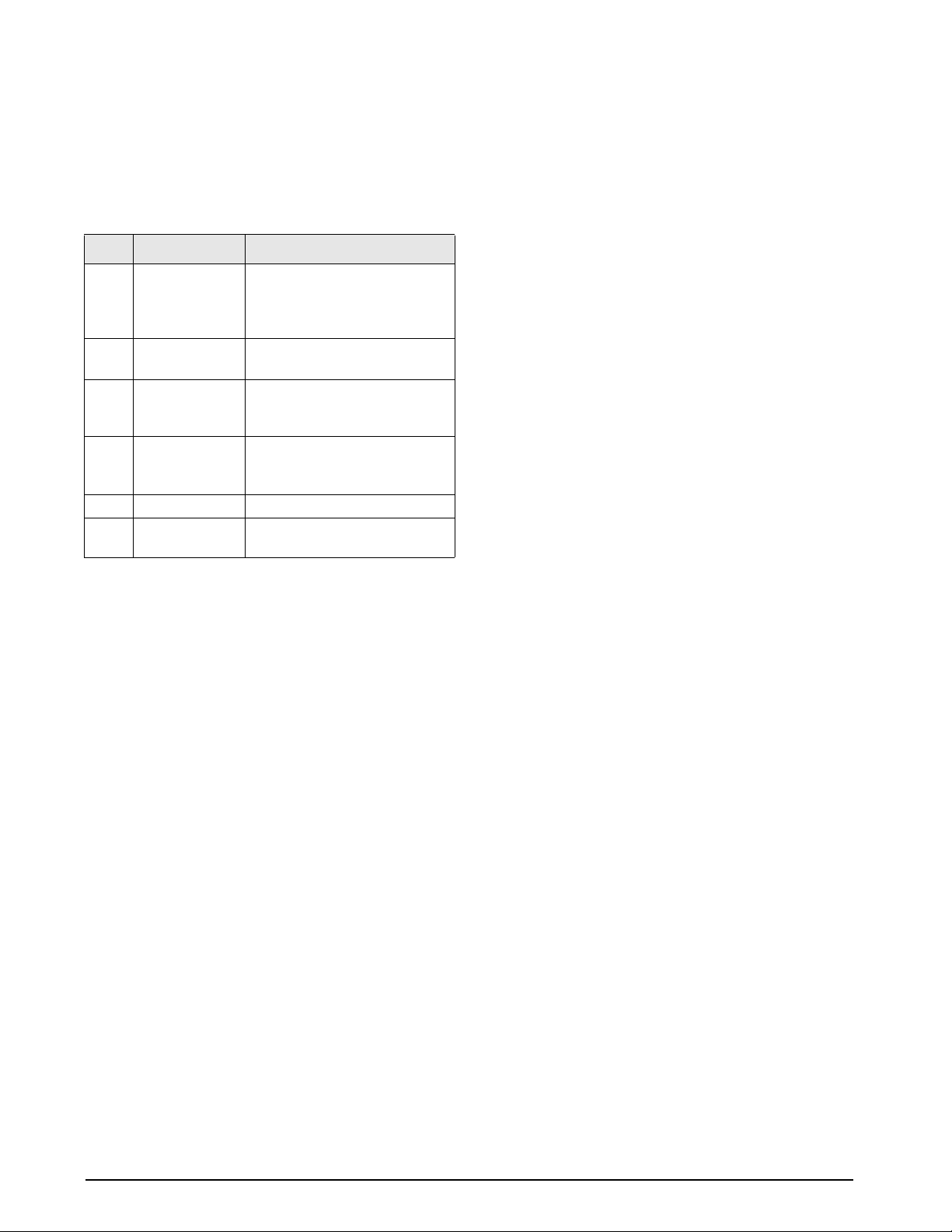
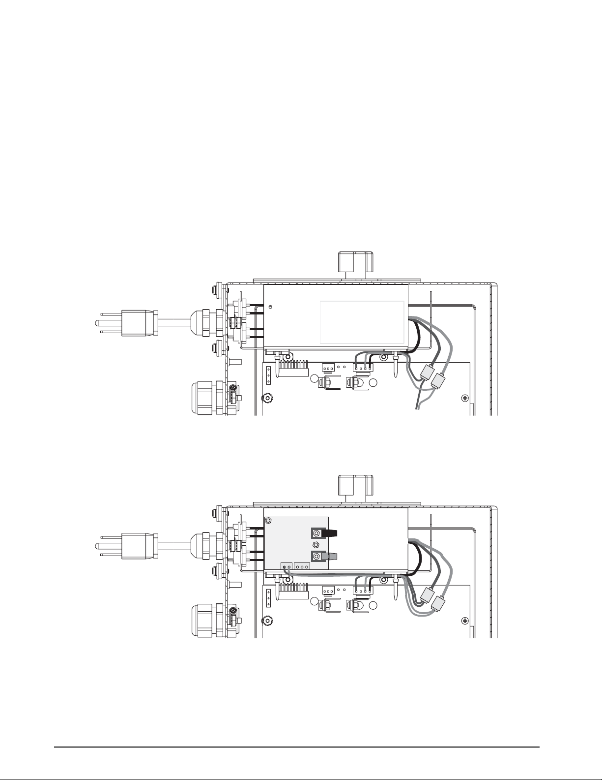
2.11.1 Copper-Wire Connection to the 920i
A basic configuration of the iQUBE is shown in Figure 2-8. A single 6-conductor load cell cable can be used both
to supply 6 VDC power to the
included in the
page 14).
iQUBE parts kit are used to tap power from the indicator power supply (see Sect ion 2.12 on
NOTE: Applications using more than two iQUBE units must use the iQUBE’s optional internal power
supply.
iQUBE and to exchange serial data with the 920i indicator. Tap and run connectors
Figure 2-8. iQUBE Copper Wire Connection to 920i, Showing RS-232 and DC Power Connections
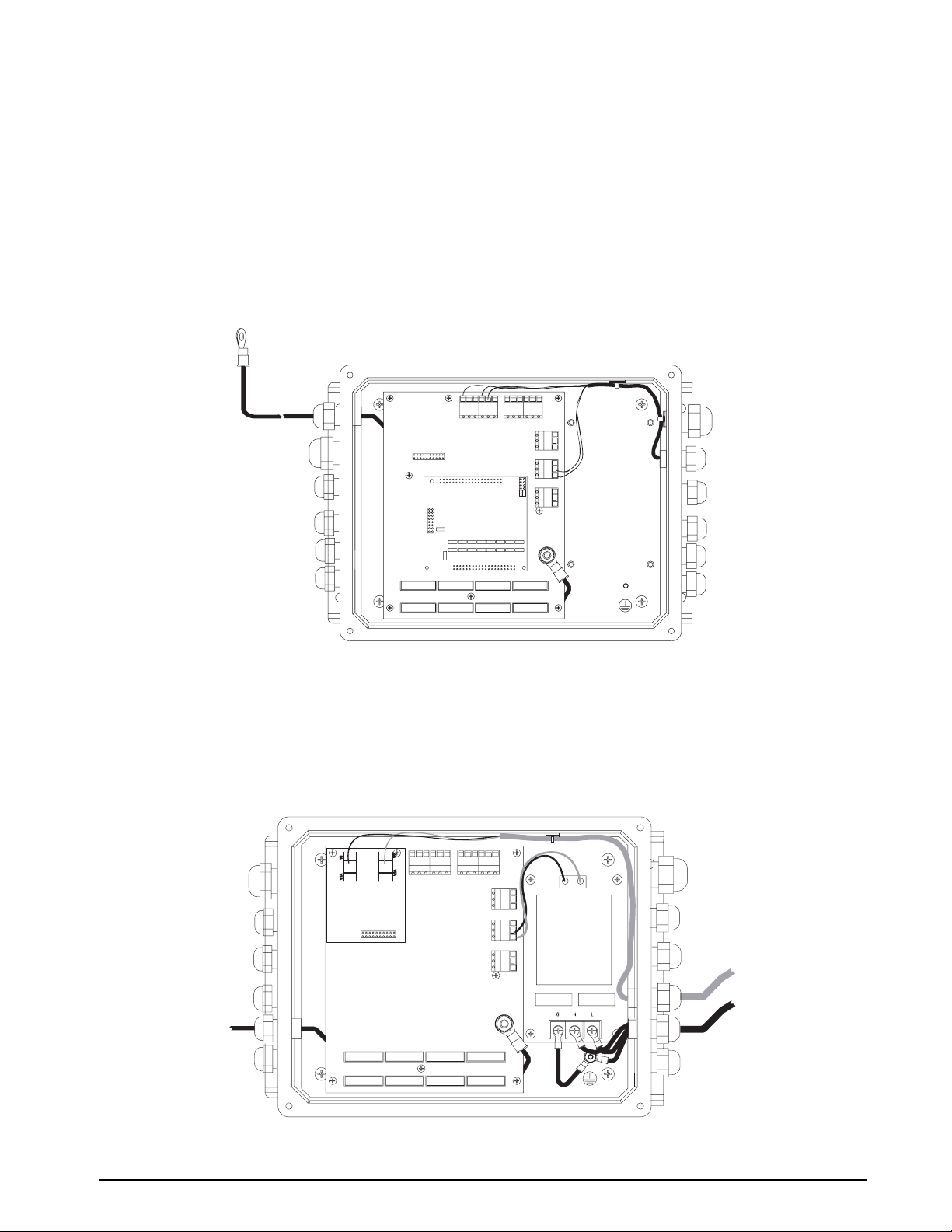
2.11.2 Fiber-Optic and Ethernet Communications
Both fiber-optic and Ethernet communications cards are available for the iQUBE. Figure 2-9 shows an iQUBE
unit with the fiber-optic card and the optional internal power supply installed.
An internal fiber-optic module for the
between the
iQUBE and the 920i. The optional remote fiber-optic interface can also be used to convert digital
data carried on a fiber-optic cable from the
920i (see Figure 2-18 on page 16) allows direct fiber-optic communication
iQUBE to an analog signal for any weight indicator.
Figure 2-9. iQUBE Fiber-Optic Connection to 920i or Remote Fiber Module
Installation 11
Page 15
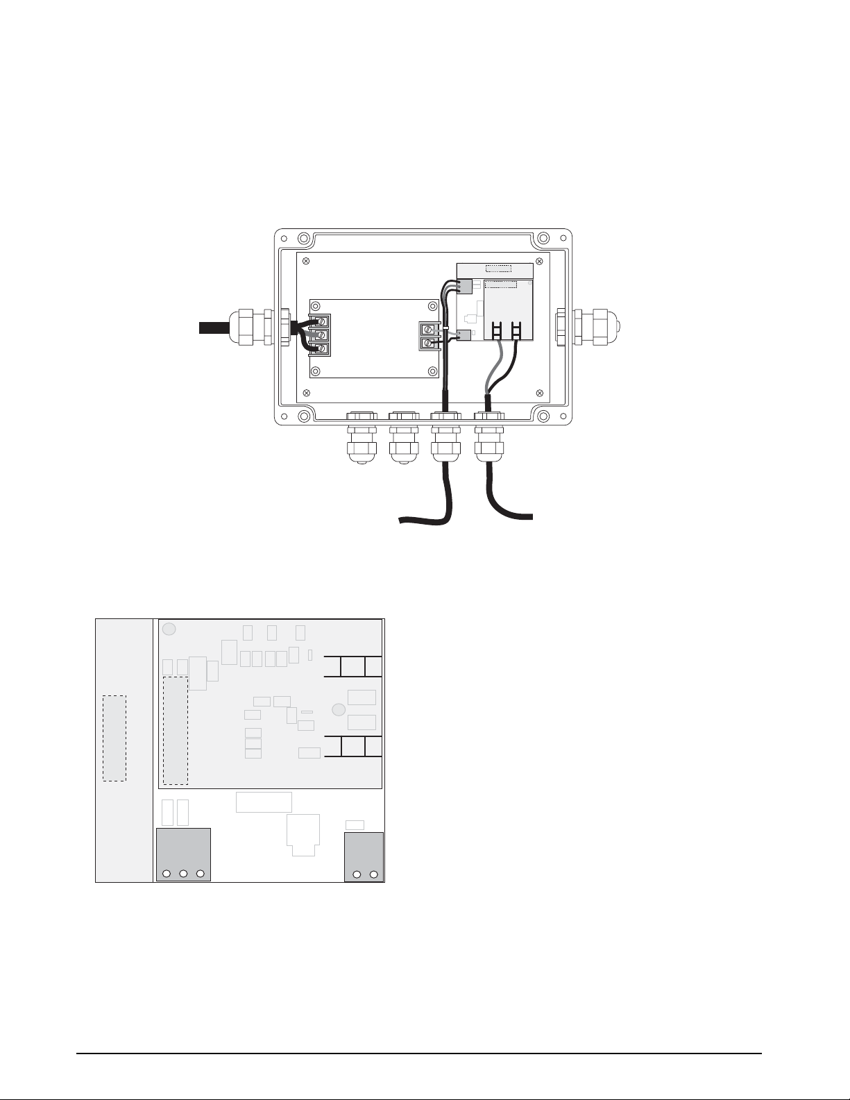
2.11.3 Remote Fiber-Optic Module (PN 77789)
The optional remote fiber-optic module provides optically isolated digital-to-analog (DAC) conversion of digital
data received from the
iQUBE. The analog output from the module can be connected to the analog (load cell)
signal input of a standard weight indicator that can read 0-30mV (0-20mA) referenced to ground (see
Figure 2-10).
This option requires that the
iQUBE be fitted with its internal fiber-optic card (see Figure 2-9 on page 11); both
voltage- and current-based DAC cards available for the remote fiber-optic module.
J5
DAC
J3
FIBER-OPTIC
INTERFACE
V1
V1A
V2A V2
AC
POWER
IN
POWER
SUPPLY
J4
ANALOG
OUTPUT
J1
POWER
IN
ANALOG OUTPUT
TO INDICATOR
Figure 2-10. Remote Fiber-Optic Module
Figure 2-11 shows connector locations on the remote
fiber-optic interface.
(BLACK)
DAC
J5
FIBER-OPTIC
J3
INTERFACE
J4
ANALOG
OUTPUT
GND
–OUT
+OUT
V1
(BLUE)
V2
TRANSMITTER
J1
POWER
IN
+V
GND
FIBER-OPTIC INPUT
FROM iQUBE
Figure 2-11. Remote Fiber-Optic Interface, Including DAC
12 iQUBE Installation Manual
Page 16
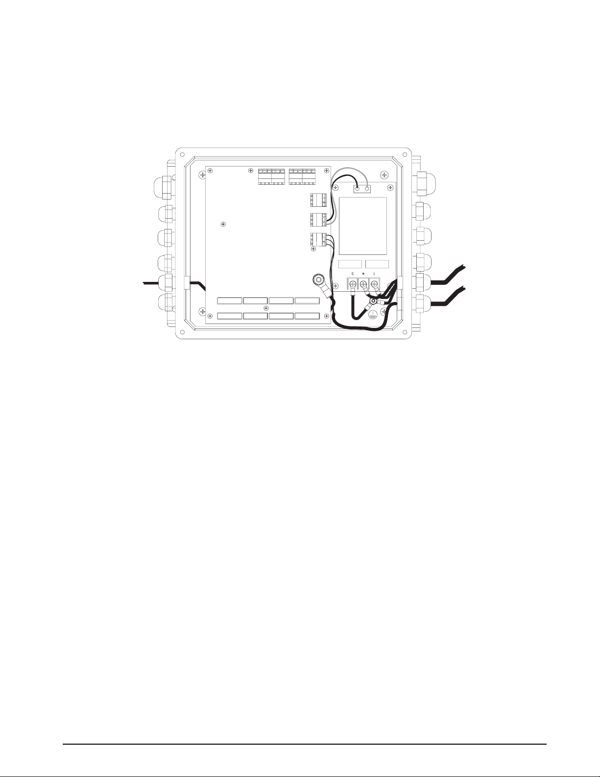
2.11.4 Analog Output
The analog output from the iQUBE can be connected to the analog signal inputs of any weight indicator that can
be read 0-30mV (0-20mA) referenced to ground (see Figure 2-12). Analog output from the
digital-to-analog (DAC) card be installed on the
iQUBE core module. Both voltage- and current-based DAC
iQUBE requires that a
cards are available. See Section 2.14.1 on page 15 for more information about DAC card installation.
NOTE: Analog output wiring must include ground wire (pin 3 on connector J9 on the iQUBE connector board).
Figure 2-12. iQUBE Analog Output Connection to Indicator
Installation 13
Page 17
2.12 Installing Tap and Run Connectors for 920i Power
iQUBE installations that are remotely powered by the
920i indicator, and those that use the 920i internal
fiber-optic module, require tap and run connectors to
draw power from the
920i power supply (see Figures
2-13 and 2-14).
To install tap and run connectors in the
920i indicator,
do the following:
1. Place red (+6V) wire from
920i power supply
inside the run channel of the tap and run
connector. The cable tie used to secure the
power supply wires may need to be cut to allow
sufficient slack in the wires.
POWER SUPPLY
2. Close side cover of connector until latched.
3. Insert tap wire (+6V supply to
connector. Use inspection port to check wire
position.
4. Use crimping tool to drive u-contact down flush
with top of connector. Close hinged top cover
until latched.
5. Repeat procedure for green (GND) wire tap and
run connector.
6. Use cable ties to secure power supply wires
inside the enclosure.
WARNING!
HIGH VOLTAGE
DISCONNECT POWER BEFORE SERVICING
iQUBE) into
J8
TAP AND RUN
CONNECTORS
GREEN (GND)
RED (+6V)
Figure 2-13. 920i Tap and Run Connector Installation
POWER SUPPLY
FIBER-OPTIC
INTERFACE
V1
V2
J4
J8
J3
TAP AND RUN
CONNECTORS
GREEN (GND)
RED (+6V)
Figure 2-14. 920i Tap and Run Connector Installation for Internal Fiber-Optic Interface
See Section 2.14.4 on page 16 for more information about installing the 920i internal fiber-optic interface.
14 iQUBE Installation Manual
Page 18

2.13 Installing the Optional Power Supply
The optional internal power supply provides 6VDC
power for the
sources. It is required for
include the Ethernet option or that consist of more
than two
use the internal power supply to provide electrical
isolation from the indicator.
iQUBE from 115 or 230 VAC power
iQUBE configurations that
iQUBE units. Fiber-optic configurations can
F1
GNL
–DC
2.14.2 iQUBE Internal Fiber-Optic Option
To install the internal iQUBE fiber-optic interface
card, carefully align the option card connector with
connector J6 on the connector board (see Figure 2-2
on page 4). Press down to seat the option card in the
connector.
V1
V1A
+DC
F2
Figure 2-15. Optional iQUBE 6V Power Supply
NOTE: When using DC source that is between 8 - 16
volts, remove jumper JP1, located on the back side of
the core module. See Figure 2-2 on page 4.
2.14 Installing Option Cards
General procedures for iQUBE option cards are
described below:
Option cards are not hot-pluggable.
Disconnect power to the
installing option cards.
2.14.1 Digital-to-Analog (DAC) Conversion Cards
Two DAC cards are available for both the iQUBE and
the remote fiber-optic module:
• PN 77146, 0–30 mV DAC
• PN 77797, 4–20 mA DAC
For DAC cards to be installed in either the
the remote fiber-optic module, orient the DAC card so
that, when installed, its edge is aligned with the edge
of the core module (
iQUBE) or the fiber-optic
interface board (remote fiber-optic module).
Carefully align the DAC card connector with the
board connector (J4 on the core module, J5 on the
remote fiber-optic interface board). Press down to seat
the DAC in the board connector.
See Figure 2-2 on page 4 for core module location;
see Figure 2-10 on page 12 for remote fiber-optic
interface location.
iQUBE before
iQUBE or
Connector for iQUBE
Expansion Module Slot
V2A V2
J1
Figure 2-16. iQUBE Internal Fiber-Optic Option Card
2.14.3 iQUBE Internal Ethernet Option
To install the internal iQUBE Ethernet cards, carefully
align the option card connector with connector J6 on
the connector board (see Figure 2-2 on p age 4). Press
down to seat the option card in the connector.
NOTE: The optional internal iQUBE power supply is
required for configurations that include the Ethernet
option.
RJ-45
JACK
22
1
LED
ARRAY
Connector for iQUBE
Expansion Module Slot
12
J2
11
J1
Figure 2-17. iQUBE Internal Ethernet Option Card
Installation 15
Page 19

2.14.4 920i Internal Fiber-Optic Option
To install the 920i internal fiber-optic interface,
position the adhesive square on the top of the
920i
power supply shield (see Figure 2-14 on page 14).
Press the fiber-optic interface backplate onto the
adhesive square, then install the interface board onto
the backplate.
Attach fiber-optic cables to connectors V1 (receive)
and V2 (send). Attach RS-232 communications cables
from connector J3 on the fiber-optic interface to any
available
920i serial port. Use cable ties to secure
communications cables inside the indicator enclosure.
Power to the
920i internal fiber-optic interface is
provided by tap and run connectors on the +6V and
GND wires between the
920i power supply and the
indicator CPU board. Attach power supply wires to
connector J4 on the fiber-optic interface. See
Section 2.12 on page 14 for installation information.
(BLACK)
V1
DETECTOR
GND
J3
(BLUE)
V2
1
TXD
RXD
TRANSMITTER
GND
J4
POWER SERIAL DATA
1
+6V
Figure 2-18. 920i Internal Fiber-Optic Option Card
2.15 Fuse Replacement
Fuse F1 on the iQUBE connector board (see
Figure 2-2 on page 4) provides protection for power
supplied to the connector board and core module at
connector J10. See Section 9.5 on page 50 for
complete fuse specifications.
To protect against the risk of fire, replace
fuses only with same type and rating fuse.
2.16 Parts Kit Contents
Table 2-8 lists the parts kit contents for the iQUBE.
PN Description
15631 Cable ties, 3-in. nylon (15)
15650 Cable tie mounts, 3/4-in. (7)
15665 Reducing glands, 1/2-in. NPT (10)
19538 Cord grip plugs (6)
42350 Capacity label (1)
60940 120Ω resistors for RS-485 termination (2)
67063 Enclosure mounting tabs (4)
71349 1-in. polycarbonate breathing filter (1)
77925
78476 Cage clamp tools for load cell connectors (2)
80331 Tap and run connectors (2)
83937
77224 Installation manual (1)
Revolution III configuration software CD (1)
iQUBE Tec hn i cal v id e o (1 )
Table 2-8. Parts Kit Contents
16 iQUBE Installation Manual
Page 20

2.17 Replacement Parts and Assembly Drawings
Table 2-9 lists replacement parts for the iQUBE models, including all parts referenced in Figures 2-19 and 2-20.
Ref Number PN Description (Quantity)
1 92938
3 14822 Machine screws, 4-40NC x 1/2 (8)
4 77140
77139
77727
5 14637 Nuts (for power ground), 1/4-20NC (2)
6 31546 1/4-in. internal tooth lock washers (for power ground) (3)
7 14729 Bolt (for power ground), 1/4-20NC x 3/4 hex head (1)
8 15655 Cable grip, 3/8 NPT (9)
9 15656 Lock nut, 3/8 NPT (10)
10 15628 Cord grips, 1/2-in. NPT (10)
11 15630 Lock nuts, 1/2-in. NPT (10)
12 91785
18 77248
77247
19 16892 Ground/Earth label (1)
21 91896 Mounting panel assembly (1)
— 71027 Fuse F1 (see Figure 2-2 on page 4). 2A time-lag,
— 83052 Splice connector for fiber-optic cable
— 77224 Installation manual (1)
— 77925
— 83897
To protect against the risk of fire, replace fuses only with same type and rating fuse.
See Section 9.5 on page 50 for complete fuse specifications.
iQUBE cover decal (1)
iQUBE connector board, 4-channel (1)
iQUBE connector board, 8-channel (1)
iQUBE connector board, 8-channel with digital I/O (1)
iQUBE enclosure (1)
iQUBE core module, 4-channel (1)
iQUBE core module, 8-channel (1)
Wickmann TR5, type 374 (1)
Revolution III configuration software CD (1)
iQUBE Technical video (1)
See Figure 2-19 on page 18
See Figure 2-20 on page 19
Table 2-9. Replacement Parts
Installation 17
Page 21

1
3
4
5
6
7
8
9
18 iQUBE Installation Manual
12
Figure 2-19. iQUBE Enclosure Assembly
10
11
Page 22

18
19
21
Figure 2-20. iQUBE Assembly
Installation 19
Page 23

3.0 920i Indicator Configuration
To configure the 920i indicator, the indicator must be placed in setup mode. The setup switch is accessed by
removing the large fillister head screw on the desktop and universal enclosures. Switch position is changed by
inserting a screwdriver into the access hole and pressing the switch.
When the indicator is placed in setup mode, a series of menus is shown across the top of the display, along with
the words
920i Installation Manual for complete information.
When configuration is complete, press the
switch access screw.
•The
•
3.1 Configuration Methods
The iQUBE can be configured for use with the 920i indicator by using the indicator front panel keys to navigate
through a series of configuration menus or by sending commands or configuration data to an indicator serial port.
Configuration using the menus is described in Section 3.4 on page 22.
Configuration using the serial port can be accomplished using either the serial commands described in the
Installation Manual and Section 8.0 on page 42 of this manual, or by using the iRev configuration utility (see
Section 4.0 on page 29).
NOTE: Some configuration parameters, such as those used to configure the 920i display and widgets, cannot be
accessed through the configuration menus.
for the
Scale Configuration. The SCALES menu is highlighted as the first used to configure the indicator . See the
Exit or Save and Exit softkey to exit setup mode, then replace the setup
Exit softkey exits setup mode without saving parameter changes to NV RAM. Changes made to the
configuration remain in the system until indicator power is cycled.
Save and Exit writes all parameter changes to flash memory before returning to normal mode.
920i
iRev provides the most complete and efficient configuration interface
920i.
3.2 920i–iQUBE Menu Configuration
With both the iQUBE and the indicator powered off, connect Port 3 (or higher) of the indicator serial port to pins
2, 3, and 6 of connector J7 on the
Power up the indicator and the
mode.
1. Use the SERIAL menu to set up the following parameters. See Figure 3-2 on page 22 for a diagram of this
portion of the
920i SERIAL menu. See also Table 3-1 on page 23.
CONFIG: Use the CONFIG parameter to select the
system with an 8-channel primary board and no secondary units is designated 8/0/0/0; an 8-channel primary
board with a 4-channel secondary is designated 8/4/0/0.
CELLS: Enter load cell IDs, capacities, factory sensitivity values, and serial numbers. Load cell capacities
and sensitivities are the only required parameters.
SECTION: Specify the relationship between cells as paired (PAIR) or circular (CIRC). Platforms with an
odd number of cells must specify CIRC.
PLATFM: The platform setup display is divided into three areas:
• Platform (middle section): Highlight the platform being configured, then use the
to the Available Cells section.
• Available Cells (left section): Use this section to assign cells to the platform. Use the
to highlight the desired cell, then use the
assignment is important! See Section 2.3 on page 3 for information about the load cell build order.
• Associated Cells (right section): Lists cells that have been assigned to the platform. You can use the
Remove softkey to remove cells from the platform. As cells are moved to the Associated Cells side a
section diagram of the platform is displayed in the center of the screen.
Press
Done when all required cells have been assigned to the platform.
iQUBE connector board.
iQUBE. Use the setup switches to place both the iQUBE and the indicator in setup
iQUBE board and cell configuration. For example, a
left arrow key to move
up and down keys
Add softkey to associate the cells with the platform. Order of
20 iQUBE Installation Manual
Page 24

SYSTEM: The system setup display is divided into three areas:
• System (middle section): Highlight the system being configured, then use the
left arrow key to move to
the Available Platform section.
• Available Platforms (left section): Use this section to assign platforms to the system. Use the
down keys to highlight the desired platform, then press the Add softkey to assign the platform to the
system.
• Associated Platforms (right section): Lists platforms that have been assigned the system. A system
diagram is displayed in the center of the screen.
Press
Done to return to the configuration menu.
2. Press the
press
3. Cycle power on the
4. Press the
5. Return the
6. Continue configuration of the indicator as described in the
iQUBE-920i functions and setup information are described in the sections listed below:
Other
Download softkey. Use the up and down keys to select Download iQUBE configuration only, then
enter.
iQUBE to initialize the changed configuration.
Save and Exit softkey.
920i to setup mode.
920i Installation Manual.
• Calibration: see Section 5.0 on page 31
• Contact information: see Section 7.3 on page 40
• Diagnostic setup: see Section 3.4.2 on page 25 and Section 6.0 on page 34
• Alert messaging: see Section 7.0 on page 38
up and
3.3 Configuration and Calibration Summary
Step 1 Step 2
Config
Associate
Serial Port
Port
Number
Config
Cells
Platform
System
iQUBE
Scale
Port
Step 3
Config
Scale
Grads
Format
Step 4
Calibr
WZero
Theoretical
Calibration
Step 5
Calib
Cal-
Match
WVal
Final
Calibration
(WSpan)
Download
to J-Box
Figure 3-1. Configuration and Calibration Summary
920i Indicator Configuration 21
Page 25

3.4 iQUBE-Specific Menu Structures and Parameter Descriptions
The following sections provide graphic representations of iQUBE-specific 920i menu structures and tables
describing the menu parameters. Default values are shown in bold type; numeric ranges and string values are
shown in italic type. Parameters shown surrounded by a dotted-line box only appear under the special
circumstances explained under each box.
NOTE: Port 3 is the default port for most print formats. If the iQUBE is attached to the 920i using port 3, ensure that the serial
print format is not also routed to port 3. Use the PORT parameter to change the print format serial port assignment.
3.4.1 SERIAL Menu, iQUBE Submenu
SCALESSERIAL FEATURE PFORMT SETPTS DIG I/O ALGOUT VERS
PORT 3
PROGIN
See Port 1–2 Menus
CONFIG SECTIONCELLS
8/0/0/0
8/4/0/0
8/4/4/0
8/8/0/0
4/0/0/0
4/4/0/0
4/4/4/0
4/4/4/4
CMD
CELLA1–
CELLA8
List of Cells
for
CONFIG type
ID
load_cell_ID
SCALE IND SC IQUBE
See Port 3–4 Menus
PLATFM ALGOUT
PAIR
CIRC
CAPCTY
75000 3.000000
capacity
List of Cells
and Platforms
SENS
sensitivity
1–4
SYSTEM
Platforms
and Systems
SRLNUM
serial_number
List of
SOURCE
OFF
ON
PORT 4
Same as PORT 3
FULLSC
300000.0
number
…
DIGIO
…
BIT 1
See DIG IO Menu Selections
BIT 8
22 iQUBE Installation Manual
IQDIAG
See IQDIAG
Submenu
Figure 3-2. SERIAL Menu, iQUBE Submenu
TESTCOM
VALIDAT
PORTTYPE
RS232
RS485
Page 26

SERIAL Menu (iQUBE Submenu)
Parameter Choices Description
CONFIG 8/0/0/0
8/4/0/0
8/4/4/0
8/8/0/0
4/0/0/0
4/4/0/0
4/4/4/0
4/4/4/4
4/8/0/0
CELLS CELLA1–CELLA8
List of cells for
CONFIG type
SECTION PAIRED
CIRCULAR
PLATFM List of cells and
platforms
SYSTEM List of platforms
and systems
ALGOUT SOURCE
FULLSC
DIGIO BIT 1 – BIT 8
IQDIAG ZEROREF
CELLBAL
LDRIFT
PKtoPK
CELLEMU
MOTBAND
TESTCOM VALIDAT Select VALIDAT to run a communication validation test for one or more attached
Specifies the
The first value (8 or 4) designates the number of channels on the iQUBE primary board;
the remaining three values represent attached secondary units, if any, and the number of
channels on each secondary board.
NOTE: The
exceed 16; an 8-channel board cannot be defined as a 4-channel board.
Depending on the value specified for CONFIG, load cells are listed using default names
with the format CELLxy, where x is the board identifier (A is the primary unit; B, C, and D
are secondary units), and y is a designation (1–4 or 1–8, depending on the number of
channels supported by the board), for the individual load cell.
Subparameters allow load cell ID, capacity, sensitivity, and serial number to be specified.
See descriptions under Level 4 Submenus.
Specifies whether the load cells defined for the section are referenced to each other as
pairs or in a circular relationship. Sections with an odd number of cells must specify
CIRCULAR. Full diagnostic capability requires PAIRED section configuration.
See Section 2.3 on page 3 for information about load cell build order.
Use the Add softkey to associate load cells with platforms.
Use the Add softkey to associate platforms with an
consist of 1–4 platforms.
Specifies the source system and full scale value for an iQUBE analog output. See
descriptions under Level 4 Submenus.
For iQUBE models with digital I/O, specifies the function of each of the digital I/O bits.
See the 920i Installation Manual, PN 67887, for information about digital I/O functions.
See Level 4 Submenus, Figure 3-3 on page 25, and Table 3-2 on page 26.
iQUBE system configuration.
iQUBE allocates either 4 or 8 channels per board. Total channels cannot
iQUBE system. A system can
iQUBEs. The validation test returns the serial numbers of all attached iQUBEs.
PORTTYPE RS232
RS485
Level 4 Submenus
ID load_cell_ID Specifies the load cell ID. Press enter to exit this parameter.
CAPCTY 75000
capacity
SENS 3.000000
sensitivity (mV/V)
SRLNUM serial_number Optional. Enter the load cell serial number.
Specifies the port designation.
Enter the rated load cell capacity.
Enter the actual or nominal load cell millivolt/volt sensitivity.
Table 3-1. Serial Menu Parameters, iQUBE Submenu
920i Indicator Configuration 23
Page 27

SERIAL Menu (iQUBE Submenu)
Parameter Choices Description
SOURCE OFF
system_name
FULLSC 300000.0
value (weight)
BIT 1 – BIT 8 —
ZEROREF ENABLE
THRH
%THRH
DELAY
CELLBAL ENABLE
THRH
%TOLR
LOAD
LDRIFT ENABLE
LIMIT
%LIMIT
TIME
LOAD
PKtoPK ENABLE
LIMIT
CELLEMU ENABLE
TYPE
MOTBAND 10.00000
value (weight)
Analog output source. If analog output DAC is installed, assign system name.
Analog output full scale range. Specifies the weight value at the full scale analog output
(30 mV or 20 mA).
Specifies the function of the digital I/O bit. See the
for more information.
Zero reference diagnostic subparameters. See Table 3-2 on page 26. The zero reference
test compares the millivolt output of section pairs when half of the load cell outputs are
below the specified threshold value.
Cell balance tolerance diagnostic subparameters. See Table 3-2 on page 26. The cell
balance test checks the outputs of section pairs for equal load distribution.
Load cell drift diagnostic subparameters. See Table 3-2 on page 26.
Peak-to-peak diagnostic subparameters. See Table 3-2 on page 26.
Cell emulation. See Table 3-2 on page 26 for more information.
Motion band. See Table 3-2 on page 26 for more information.
920i Installation Manual, PN 67887,
Table 3-1. Serial Menu Parameters, iQUBE Submenu (Continued)
24 iQUBE Installation Manual
Page 28

3.4.2 iQUBE Submenu, IQDIAG Parameters
Figure 3-3 shows the IQDIAG parameters on the IQUBE submenu. The IQDIAG parameters allow
customization of the
iQUBE’s diagnostic routines.
DIGIO
ZEROREF
ENABLE
ON
OFF
LDRIFT
ENABLE
ON
OFF
THRH
0.125000
number
LIMIT
0.025000
number
IQDIAG
If ENABLE = ON
If ENABLE = ON
%THRH
25 900
number
%LIMIT
10 30
number
TESTCOM
DELAY
number
TIME
number
CELLBAL
ENABLE
ON
OFF
LOAD
5000.000
number
THRH
0.200000
number
PKtoPK
ENABLE
ON
OFF
%TOLR
25 5000.000
number
If ENABLE = ON
LIMIT
0.125000
number
If ENABLE = ON
LOAD
number
CELLEMU
ENABLE
ON
OFF
TYPE
AUTO1
AUTO2
MANUAL1
MANUAL2
If ENABLE = ON
MOTBAND
10.00000
number
Figure 3-3. IQDIAG Submenu
920i Indicator Configuration 25
Page 29

iQUBE Submenu, IQDIAG Parameters
Parameter Subparameter Choices Description
IQDIAG ZEROREF
CELLBAL
LDRIFT
PKtoPK
CELLEMU
Level 5 Submenus
ZEROREF ENABLE ON
THRH 0.125000
%THRH 25
DELAY 900
CELLBAL ENABLE ON
THRH 0.200000
%TOLR 25
LOAD 5000.000
See descriptions under Level 5 Submenus. Each group of
can be enabled or disabled using the ENABLE subparameter.
See Section 6.0 on page 34 for more information about iQUBE diagnostic tests.
Enable zero reference diagnostics. The zero reference test checks
OFF
value (mV)
value (percent)
value (seconds)
OFF
value (mV)
value (percent)
value (weight)
for load cell output errors and inconsistencies when the scale is
unloaded.The zero reference test begins when half of the load cells
fall below the threshold value.
above the threshold value, if any are, after the time delay it looks at
that cells cell mates. If it’s cell mates fall between calculated zero
and percent threshold an error will occur. If any one fo the cell amtes
is above the percent threshold, no error will occur.
A m/v reference value at which a cell is presumed to be unloaded.
This m/v threshold value is added to the calculated zero m/v of each
cell.
Specifies a band above the calculated zero point of each load cell
allowed for a presumed zero point.
Time delay in seconds, this is the amount of time a cell must be over
the threshold value.
Enable cell balance diagnostics. The cell balance test checks for
balance between cells in a section of a scale. The test will not run
until the millivolt threshold of both cells in a section have been met
and the load value of the scale has been exceeded. As a cell in a
section increases or decreases to meet the percent tolerance an
error will be issued.
A m/v reference value at which the cells have to exceed from the
calibration zero before the test starts.
Specifies a weight ratio between the cells in a section that must be
met to obtain an error.
A weight value that the scale has to exceed before the test will run.
iQUBE determines if any cell is
iQUBE diagnostic parameters
26 iQUBE Installation Manual
Table 3-2. iQUBE Submenu, IQDIAG Parameters
Page 30

iQUBE Submenu, IQDIAG Parameters
Parameter Subparameter Choices Description
LDRIFT ENABLE ON
OFF
LIMIT 0.025000
value (mV)
%LIMIT 10
value (percent)
TIME 30
value (seconds)
LOAD 5000.000
value (weight)
PKtoPK ENABLE ON
OFF
LIMIT 0.125000
value (mV)
CELLEMU ENABLE ON
OFF
TYPE AUTO1
AUTO2
MANUAL1
MANUAL2
Enable loaded drift test diagnostics. Tests for drifting load cell
output, which can indicate binding or a deteriorating cell, when the
scale is loaded. The test begins after the load value has been
exceeded and the scale is considered out of motion (see note.)
Once the scale comes to a stable live load, the timer will start. If any
one cell is above the limit after the timer expires and any of the
remaining cells are below the percent limit, no error will occur.
NOTE: If the scale exceeds the motion band in a .5 second interval
after a stable weight, the test is reset until it comes out of motion
again.
A m/v reference representing drift allowed for cells on a loaded
scale.
Specifies the percentage difference allowed between the millivolt
output values of a cell and it’s cell mates when the scale is loaded.
Time delay in seconds between measurements of load cell values.
A weight value that the scale has to be above before the test will
run.
Enable peak-to-peak tolerance diagnostics. A back and forth
millivolt output that exceeds the limit value.
Peak-to-peak tolerance noise limit. Specifies a millivolt limit for noise
allowed between stored measurements.
Cell emulation. Specifies whether cell emulation can be used to
replace output from a bad load cell.
Type 1 selections (AUTO1, MANUAL1) use a cell emulation
algorithm designed for truck scales. Type 2 selections (AUTO2,
MANUAL2) use an algorithm for hopper and pallet scales. See
NOTE below for additional information about using Type 2
selections.
MOTBAND — 10.00000
value (weight)
Table 3-2. iQUBE Submenu, IQDIAG Parameters (Continued)
AUTO selections specify that the
cell emulation, based on diagnostic tests, and automatically applies
the selected algorithm to replace the output of a defective cell.
MANUAL selections allow the operator to toggle between actual
and emulated load cell outputs by using the
Type 2 selections (AUTO2, MANUAL2) require the “snapshot”
function (Snapshot softkey on the diagnostic display) be executed
while the scale is weighing properly. The snapshot provides the
weight distribution reference used during cell emulation.
Platform motion band. Specifies the amount of weight change
allowed in a 0.5-second interval. Diagnostic tests are run only when
platform stability is within the specified motion band.
iQUBE determines when to apply
920i diagnostic display.
920i Indicator Configuration 27
Page 31

3.4.3 PFORMT Menu
See the 920i Installation Manual, PN 67887, for general information about print formats. See Section 7.2 on
page 39 for information about the ALERT print format.
NOTE: Port 3 is the default port for most print formats. If the iQUBE is attached to the 920i using port 3, ensure that the serial
print format is not also routed to port 3. Use the PORT parameter to change the print format serial port assignment.
SCALESSERIAL FEATURE PFORMT SETPTS DIG I/O ALGOUT VERS
GFMT NFMT ACCFMT SPFMT TRWIN TRWOUT TRFMT
Same as GFMT
AUXFMT
Same as GFMT
format
PORTFMT
PORT 3
PORT 4
PORT 1
PORT 2
NOTE: Default port for
ALERT format is PORT 1
HDRFMT1
format
HDRFMT2
format
Figure 3-4. PFORMT Menu
ALERT
AUDITFMT
Same as GFMT
28 iQUBE Installation Manual
Page 32

4.0 PC Configuration
When used with the 920i indicator, the iQUBE can be configured using a PC running either the iRev or the
Revolution III program. iRev allows complete configuration of the 920i, with the capability to download the
iQUBE configuration from the indicator to the junction box. Revolution III can be used to configure the iQUBE
directly, for use with any indicator. iQUBE configurations created using Revolution III can be uploaded to the
920i.
4.1 Using Revolution III
The Revolution III configuration utility can be used to
iQUBE configuration parameters for use with any
set
indicator. When
complete, configuration data is downloaded to the
iQUBE.
Revolution III supports both uploading and
downloading of
capability allows configuration data to be retrieved
from one
iQUBE, edited, then downloaded to another.
Revolution provides online help for each of its
configuration displays.
To use
Revolution III, do the following:
1. Install
personal computer running Windows
later. Minimum system requirements include a
processor speed of at least 166MHz, 32MB of
memory (64MB recommended, required for
NT4, 2000, XP), and at least 40MB of available
hard disk space for installation.
2. With both the
connect the PC serial port to pins 2, 3, and 6 of
connector J7 on the iQUBE connector board.
(See Figure 2-2 on page 4 and Figure 2-4 on
page 7).
3. Power up the PC and the
switch to place the
4. Start the
4.1.1 Revolution III Configuration
To configure the iQUBE using Revolution, do the
following:
1. With the PC and
Revolution III program running, select
from the File menu.
2. On the Select Indicator display, highlight the
iQUBE icon, for the correct core version, see
Figure 2-2 on page 4, click the radio button
New Configuration File, then click OK. The
for
iQUBE Information Display is shown.
3. Select
bar on the iQUBE Information Display (see
Figure 4-1). The Configuration submenu is
shown.
Revolution III configuration is
iQUBE configuration data. This
Revolution III on an IBM-compatible
iQUBE and the PC powered off,
iQUBE. Use the setup
iQUBE in setup mode.
Revolution III program.
iQUBE connected and the
Configuration from the left-hand tool
®
98 or
New
Figure 4-1. Revolution iQUBE Display
4. Select Core. Use this screen to set the Auto
Transmit Port and section type. Note: As you
set up
iQUBE you will be moving down
through the configuration menu pages.
5. Select the
Cells Configuration display. Use this
display to select the load cells used in the
iQUBE system by checking the box to the left
of each cell. Enter load cell data such as
factory sensitivity, serial numbers, and
capacity on the General Information sheet for
each cell.
6. Select the
Platforms Configuration display.
Cells that were checked on the Cells screen
are now listed as Available Load Cells for the
iQUBE.
7. Click on
Platform 1.
8. Double-click on each available load cell to
move the cell into the Assigned Load Cell
column for Platform 1.
NOTE: You can rearrange the Assigned Cells by
clicking on individual cells and then using the up or
down arrows to change the position of the cell.
As cells are added to the Assigned Cell
column, a Section Format Diagram is
displayed at the bottom of the screen.
9. Select the
10. Click on
Systems display.
System 1.
11. Platform 1 is now shown in the Assigned
PC Configuration 29
Page 33

Platforms field. Click the Platform 1 box to
assign Platform 1 to System 1. Use the
General display to enter scale sys tem
parameters.
4.1.2 Downloading to the iQUBE
Once configuration is complete, you must download
the configuration data from the PC to the
iQUBE.
1. Go to the Communications menu and select
Connect… Revolution automatically detects
iQUBE communications port.
the
2. Return to the Communications menu and
select
Download Configuration. Click Begin to
initiate the download. Downloading may take
up to 30 seconds.
4.2 Using iRev
The iRev utility provides a suite of functions used to
support configuration, calibration, customization, and
backup of the
configuration,
designs, stream and ticket formatting, setpoint
configuration, database management, and
program editing are all supported by iRev.
Calibration values, scale, setpoint, and display
configuration, database tables, and user programs, can
be both saved and restored to the
supporting applications provided with
•The
compiler for writing
• The Rice Lake Web Update utility uses your
internet connection to check for and download
updates to the
• The iLaunch utility can be installed to display a
set of icons used for convenient startup of
and its supporting applications, including the
Help system.
Hardware and Software Requirements
Minimum system requirements: 166 MHz,
x86-compatible, with 32MB RAM (64MB for NT4/
2000), 40MB disk space. Recommended system: 233
MHz, x86-compatible or greater, with 64MB RAM,
40 MB disk space.
iRev runs on most Windows
including Windows 95 (original release), Windows 95
OSR2, Windows 98, Windows 98 SE, Windows ME,
Windows NT 4.0 (SP4 or greater), Windows 2000, and
Windows XP (Home or Professional).
When used with the original release of Windows 95,
iRev requires an updated version of TAPI. The TA PI
update is included on the
available from the RLWS web site at
920i software. Hardware and software
920i display setup for up to ten screen
iRite
920i using iRev. Other
iRev include:
iRev Editor provides a basic editor and a
iRite applications.
iRev and 920i software.
iRev
®
operating systems,
iRev installation CD and is
www.rlws.com.
Internet Explorer
iRev help system. Explorer is included on the iRev
the
®
(IE) 4.0 or greater is required to use
installation CD or is available from Microsoft
Corporation.
iRev is installed using a standard Windows installation
procedure.
installed in a directory named iRev; icons for the
iRev applications and support files are
iRev
application, the iRev Editor, Uninstall, and the Rice
Lake Web Update utility are placed in the Windows
Start menu.
See the
about using
iRev Configuration
920i Installation Manual for more information
iRev.
Configuration of the iQUBE using the iRev program is
similar to using the
920i menus. Use the Too l s toolbar
selection to configure the serial port used for the
iQUBE connection.
Figure 4-2 shows one of the
iRev serial port
configuration displays.
Figure 4-2. iRev Serial Port Configuration Display
Once iRev configuration of the 920i is complete, use
the
Download Configuration function on the iRev
Communications menu to download the configuration
to the indicator.
To download the
Download softkey on the 920i serial port IQUBE
the
CONFIG menu. Use the
Download iQUBE configuration only, then press enter.
At version 2.05 and higher, the
iQUBE is done automatically after the iRev download.
920i configuration to the iQUBE, use
up and down keys to select
920i download to
30 iQUBE Installation Manual
Page 34

5.0 Calibration
The iQUBE can be calibrated using the 920i front panel or Revolution III. The following sections describe the
calibration procedure for each of the calibration methods.
SCALESSERIAL FEATURE PFORMT SETPTS DIG I/OALGOUT VERS
SCALE x
…
VISIBLE GRADS FORMATCALIBR
WZERO
WZERO
display
Theoretical
Calibration
POINT 3
…
CALIB SECTIONS CORNERS
List of
platforms
PLAT x
NOTE: Perform Corner
or Section-Match
WVAL WSPAN WLIN
weight_value
POINT 4 POINT 5 POINT 1 POINT 2
Sections
display/tweak
If
SECTION=PAIRED
mV_value
Corners
display/tweak
Figure 5-1. CALIBR Submenu
REZERO
Deadload
adjustment
5.1 920i Front Panel Calibration
The CALIBR submenu (under the SCALES menu,
see Figure 5-1) is used to calibrate the
iQUBE at the same time.
Three calibration methods can be used to trim the load
cells:
• Theoretical
• Cal-Match
• Manual trimming
5.1.1 Theoretical Calibration
To perform a theoretical calibration of the iQUBE
using the 920i front panel, press the Theoretical
Calibration
softkey. The dead load value is captured
and the cells trimmed based on the capacity and
sensitivity values entered for the cells. Scale capacity
is set at the total of the load cell capacities.
920i and the
5.1.2 Cal-Match Calibration
To perform a Cal-Match calibration of the iQUBE
using the 920i front panel, do the following:
1. Place the indicator in setup mode (display
reads
Scale Configuration) and remove all
weight from the scale platform.
2. With the SCALES menu highlighted, press
down key to show the CALIBR parameter.
the
3. From the CALIBR parameter, press
down
again to show a list of configured platforms
and select the platform to be calibrated.
4. Press
down to go to the test weight parameter
WVAL). By default, the test weight value is set
(
to the total load cell capacity. Use the numeric
keypad to enter the test weight, then press
enter.
5. Press the
Cal-Match softkey to continue
Calibration 31
Page 35

calibration. NOTE: Cal-Match calibration can
be canceled by pressing the
6. Ensure scale is empty, then use the
down keys to select Corner Cal-Match (see
Figure 5-2
) or Section Cal-Match. Press enter.
CLEAR key.
up and
The iQUBE calculates the zero reference
point.
Figure 5-2. 920i Cal-Match Selection
7. The display now prompts Cal-Match Point 1.
Place a test weight over the cell or section to
be tested, then press
enter. NOTE: It is not
necessary to measure the cells in any
particular order.
8. Once the
iQUBE has read the cell, the 920i
display will show Cal-Match Point 2. Move the
test weight to the next cell or section and
enter. Repeat until all cells have been
press
measured.
9. When the last cell has been measured, the
iQUBE automatically sets the load cell trim
factors. The
Complete
10. Press
up to return to the SCALES menu, or
920i display shows Calibration
.
press the Save and Exit softkey to exit setup
mode.
NOTE: Cal-Match calibration can be performed using
a vehicle as the test weight, but a smaller footprint and
heavier weight value will yield better results.
Mechanical characteristics of the scale may prevent
Cal-Match from automatically computing load cell
trim factors.
5.1.3 Manual Trim Factor Adjustment (Tweaking)
Section or corner trim factors can be manually
tweaked. When using the
use the
up or down navigation key to select the section
or corner to be adjusted, then use the
+
softkey to adjust the value. The displayed weight for
iQUBE with a 920i indicator ,
Twe a k – or Tw e ak
the scale system is shown at the bottom of the weight
column.
Tweaking can be performed following a Cal-Match
calibration or when replacing a load cell.
5.1.4 Final Calibration
The span and linear calibration displays provide a
Calibration softkey to perform a traditional calibration
for the selected point. Enter the weight value under
WVAL, then press the
Calibration softkey under
WSPAN for each platform. Continue under WLIN for
systems using linear calibration.
Trim factors displayed for sections or corners can be
manually tweaked up or down. The cell with the
lowest output is given a trim factor of 1.0000.
5.2 Revolution III Calibration
Cal-Match Calibration
With the iQUBE connected to a PC running the
Revolution III program, do the following:
1. From the Interactive menu, select
Load Cell Matching…
Figure 5-3. Cal-Match Load Cell Matching Display
(see Figure 5-3).
2. Remove all weight from the scale platform.
Click on
No Load. The word Transm i t t i n g is
displayed while the no-load values are
calculated. This process can last up to 45
seconds.
3. Enter the test weight value in the
Weight
field. You are now ready to measure
the load cell outputs using the Cal-Match
procedure.
4. Place the test weight over the cell to be
measured. It is not necessary to measure the
cells in any particular order.
5. Click the first
Measure box. As each cell is
completed the next cell becomes available for
measurement.
6. Repeat steps 4 and 5 until all cells have been
measured.
7. Click
Finish. Cal-Match automatically
calculates the load cell trim factors. These
normalized sensitivity values are displayed
for each cell in the platform.
8. Click
Exit.
Cal-Match
Calibration
32 iQUBE Installation Manual
Page 36

iQUBE calibration is complete. You can view the
active status of the cells, platform, or system by
returning to the Interactive menu and selecting
Monitoring
Auto Refresh box to automatically update the readings
from the
for cells, platforms, or systems. Click on the
iQUBE.
Status
Calibration 33
Page 37

6.0 Diagnostics
LC 1
LC 5
LC 3
LC 2
LC 4
LC 6
6.1 iQUBE Diagnostic
The iQUBE connector board provides bi-color cell
status LEDs (see Figure 2-2 on page 4) that indicate
the status of connected load cells. Table 6-1 lists the
cell status indications shown by the LEDs.
LED Color meaning
Green Load cell good
Red Load cell error
Off Disabled/no load cell connected
Table 6-1. LED Status Indications
6.2 Cell Mate Relationships
Cell mates to a specific load cell are defined as the
load cells that are horizontally or vertically adjacent to
each other. In the platform illustrat ion below LC2 and
LC 3 are cell mates to LC1 and LC2, LC3, and LC6
are cell mates to LC4.
LC 1
LC 2
Figure 6-1. Cell Mate Indications
LC 3
LC 4
LC 5
LC 6
6.3 Diagnostic Tests
The iQUBE provides a number of diagnostic tests, including boundary, weighing, and system tests (see Table 6-4
on page 37 for a list of diagnostic error messages ). The table below describes the tests that can be enabled or
disabled in the diagnostics of the
Te st Definition Description 920i Default
Zero
Reference
Cell Balance Which cell is out of balance with its
Load Cell Drift Checks for load cell outputs that
Peak to Peak
Limit
Motion Band Defined value in Grads that defines
Cell Emulation Process of inputting a value based
Which cell is out of tolerance at
zero
section cell mate when weight is on
the scale.
have changed over time with load
applied..
Check for noisy load cell output not
attributed to environmental
conditions.
a scale not in motion
on the matrix offset values gatered
at Calmatch time.
iQUBE.
Revolution III/
iQUBE Default
threshold: the upper limit of the zero reading of the
cells.
Per Cent threshold: the percentage of zero reading of
adjacent cells.
Delay: time to wait until the next testing process. 900 seconds 900 seconds
Threshold 0.200mv 200mv
Per Cent tolerance 25% 20%
Load: minimum load needed to initiate the test 5000lb 5000lb
Limit 0.025mv 0.025mv
Per Cent limit 10% 10%
Time 30 seconds 30 seconds
Load: minimum load needed to initiate the test 1000lb 1000lb
Limit 0.125mv 0.250mv
Motion band range: should be the same as
MOTBAND for truck scale
Type 1(standard truck scale): Auto 1, Manual 1
Type 2 (hopper scale configuration): Auto 1, Manual 2
0.125mv 0.200mv
25% 20%
10lb 10lb
Off Off
34 iQUBE Installation Manual
Table 6-2. iQUBE Diagnostic Settings
Page 38

Diagnostic Test Examples
Zero Reference Error
Threshold
125 (m/v)
25% Threshold
Calibrated Dead
Load
C1
C2
C3 C4
Loaded Drift Error
Limit 25 (m/v)
10% Limit
No Zero Reference Error
Threshold
125(m/v)
25% Threshold
Calibrated Dead
Load
Figure 6-2. Zero and No Zero Reference Errors
No Loaded Drift Error
C1
C2 C3
Limit 25 (m/v)
10% Limit
C1
C2 C3
C1
C2 C3 C4
C4
C4
Stable Live
Load (10lb)
Load
Figure 6-3. Loaded Drift and No Loaded Drift Error
25% C1 = 250 lbs
C2 = 1000 lbs
50% C1 = 500 lbs
C2 = 1000 lbs
75% C1 = 750 lbs
C2 = 1000 lbs
Figure 6-4. Cell Balance Error
Stable Live
Load (10lb)
Load
NOTES:
• the higher the %TOLR, the less variance
needed to obtain erroer
• The lower the %TOLR, the more variance
needed to obtain error
• Multiple sections can error at the same
time
Diagnostics 35
Page 39

6.4 Diagnostic Setup
Parameters associated with each of the iQUBE’s
diagnostic tests can be set using the
Revolution III. See Section 3.4.2 on page 25 for
or
descriptions of the
920i.
the
Figure 6-5. Revolution III Diagnostic Setup Display
6.4.1 Configuring the 920i Diagnostics Softkey
iQUBE diagnostic parameters for
When using the iQUBE with the 920i indicator, a
Diagnostics softkey can be configured to display
diagnostic information when in weigh mode. Use the
FEATURE menu, SOFTKEYS submenu, to select the
Diagnostics softkey (see Figure 6-6).
920i menus, iRev,
• Number of weighments
• Cell status for highlighted cell. Use the
indicator navigation keys to select cells.
NOTE: Displayed deadload and current values are raw
millivolt values. All diagnostic measurements use
corrected mV values:
corrected_value = current_value – deadload_value
Figure 6-7. 920i Diagnostic Display
The 920i diagnostic display can be shown by pressing
Diagnostic softkey (if configured).
the
In setup mode, diagnostic information can be shown
by going to the VERS menu., pressing the
Contact
softkey, then the Next softkey.
Access through the VERS menu also displays
softkeys for
enabled,
AUTO2 or MANUAL2 (see page 27), a
Clear Diagnostics and, if cell emulation is
Cell Emulation. If cell emulation is set to
Snapshot
softkey is also shown.
Figure 6-6. Selecting Diagnostics Softkey
6.4.2 920i Diagnostic Display
Figure 6-7 shows an example of a 920i display of
iQUBE diagnostic information. Information shown
includes the following:
• Cell name
• Cell deadload value (mV)
• Current individual cell and total values (mV)
36 iQUBE Installation Manual
6.5 Error Messages
Table 6-3 shows the alert system status messages
generated by the
Scale
Number
Scale x System boundary error:
Weighing error:
Master error:
Table 6-3. Alert Error Message Format
Error messages are displayed on the indicator and can
be used by print formats and
iQUBE.
Status Message
Cell Error
Messages
Error 1 Cell
Error 2 Cell
Error 3 Cell
iRite user programs.
Cell ID
An,Bn,Cn
,Dn
Page 40

Table 6-4 lists the system and cell error messages.
System Error Message Cell Error Message Error Categories
Boundary Error Error 1 Cell Not Detected
AtoD Not Responding
Cell At Rail
Cell Over/Under Range
Weighing Error Error 2 Cell Long Term Drift Error
Cell Balance Error
Cell Noise Error
Cell At Load Drift Error
Zero Reference Cell Error
Master (Primary Unit) Error Error 3 Slave (Secondary) Comm Error
Temperature Error
Low Excitation Voltage
High Excitation Voltage
Low Power Supply
High Power Supply
DtoA1 Calibration Error
DtoA2 Calibration Error
Table 6-4. System and Cell Error Messages
920i Diagnostic Display Error Codes
Table 6-5 lists error codes that may be shown in the status area of the 920i diagnostic display.Error codes are
shown in the format
OK
is shown.
Cell Error X, where X is the code listed below. If the cell is reporting no error, the message Cell
920i Error Code
A A-to-D not responding
B Cell balance error
D Load drift error
M Cell not detected
N Cell noise error
O Cell over/under range error
R Cell railed error
Z Zero reference drift error
Error Category
Table 6-5. 920i Diagnostic Display Error Codes
Diagnostics 37
Page 41

7. 0 A l e r t s
When attached to the 920i indicator, diagnostic error messages generated by the iQUBE are shown on the
indicator display. The
Ethernet card attached to a network, routed via e-mail to an alert contact.
7.1 Network Alert Notification
Figure 7-1 shows an example of a system configured to relay iQUBE alert messages through e-mail. The 920i
indicator is equipped with an Ethernet card. The 920i and Ethernet card configurations must include the
following:
• In the Ethernet card configuration,
(C4)
. This allows the 920i to set the address of the SMTP (Simple Mail Transfer Protocol) server used by the
Ethernet card.
• Set the Inactivity Timeout to ENABLE
• Set the Inactivity Timer to 0:15
•The SMTP server address must be set in the
ALERT.SERV serial command. The SMTP server address cannot be set using the
To disable alert notification, set the SMTP server address to 0.0.0.0.
•The alert contact e-mail address must be set to a valid address. This value can be set using the
(FEATURE menu, CONTACT subme nu, EMAIL parameter), through
CONTACT.EMAIL serial command.
•The
The body of the e-mail message sent to the alert contact consists of the alert format configured in the
Section 7.2 on page 39).
920i alert port must be set to the port used by the Ethernet card. This value can be set in iRev or by
using the ALERT.PORT serial command.
920i alert support also allows messages to be printed or, if the 920i is equipped with an
Connect Mode Settings, the Startup value must be set to Manual Connection
920i. This value can be set in iRev or by using the
920i menus.
920i menus
iRev, or by using the
920i (see
920i
TM
PRINT
iQUBE ALERT
error message
UNITS
Ethernet
Card
CONTACT.EMAIL = xxxxxx@yyyyyy.zzz
ALERT.FMT = alert_format
ALERT.SERV = nnn.n.nn.n
SMTP server address
Alert
NETWORK
(LAN)
SMTP
Server
nnn.n.nn.n
Figure 7-1. iQUBE Alert Notification Process
NOTE: After the SMTP address has been set to other than 0.0.0.0 (in the 920i) normal uploading/downloading
iRev (in TCP/IP mode) is not allowed and Telnet will not operate in bi-directional fashion.
with
Contact
xxxxxx@yyyyyy.zzz
NETWORK
(INTERNET)
38 iQUBE Installation Manual
Page 42

7.2 Alert Format
The default 920i alert print format is as follows:
<COMP><NL>
<COAR1><NL>
<COAR2><NL>
<COAR3><NL>
<CONM1><NL>
<COPH1><NL>
<CONM2><NL>
<COPH2><NL>
<CONM3><NL>
<COPH3><NL>
<COML><NL>
<ERR><NL>
Commands used in the 920i alert format are listed
in Table 7-1.
Command Content
<COMP> Company name (up to 30 characters)
<COAR1>
<COAR2>
<COAR3>
<CONM1>
<CONM2>
<CONM3>
<COPH1>
<COPH2>
<COPH3>
<COML> Contact e-mail address (up to 30 characters)
<ERR> Alert error message (system-generated)
<NLnn> New line (nn = number of termination (<CR/
Contact company address, lines 1–3 (up to
30 characters)
Contact names (up to 20 characters)
Contact phone numbers (up to 20 characters)
LF> or <CR>) characters). If nn is not
specified, 1 is assumed. Value must be in the
range 1–99.
Table 7-1. Alert Format Commands
Values for the contact information referenced by the
print formatting commands shown in Table 7-1 can be
set using the
920i menus (FEATURE menu,
CONTACT submenu), serial commands (see
Section 8.0 on pa ge 42),or th e
iRev configuration
utility.
See the
920i Installation Manual, PN 67887, for more
information about print formatting.
Alerts 39
Page 43

7.3 FEATURE Menu, CONTACT Submenu
SCALESSERIAL FEATURE PFORMT SETPTS DIG I/O ALGOUT VERS
CONTACT
CMPNY ADDR1 ADDR2 ADDR3 NAME1 NAME2 NAME3
company_name
address_line_1 address_line_2 address_line_3 contact_name_1
PHONE1 PHONE2 PHONE3 EMAIL
phone_number phone_number phone_number email_address
contact_name_2 contact_name_3
NEXTCAL
date
Figure 7-2. CONTACT Submenu
FEATURE Menu, CONTACT Submenu
Parameter Choices Description
Level 3, CONTACT submenu
CMPNY company_name Enter the name of the contact company or dealer.
ADDR1–
ADDR3
NAME1–
NAME3
PHONE1–
PHONE3
EMAIL email_address Enter the email address of the contact company or dealer.
NEXTCAL date Enter the next scheduled calibration date using the month/day/year format on the
address Enter up to three lines of address information for the contact company.
contact_name Enter names of up to three contact persons.
phone_number Enter phone numbers for each of the contact persons specified for the NAMEx parameter.
iQUBE alert support is used to send automated alert messages (see Section 7.0 on
If the
page 38), enter the email address to which the alert messages will be sent.
DATEFMT parameter. Separator characters are not required.
40 iQUBE Installation Manual
Table 7-2. CONTACT Submenu Parameters
Page 44

7. 4 P F O R M T M e n u
See the 920i Installation Manual, PN 67887, for general information about print formats. See Section 7.2 on
page 39 for information about the ALERT print format.
NOTE: Port 3 is the default port for most print formats. If the iQUBE is attached to the 920i using port 3, ensure that the serial
print format is not also routed to port 3. Use the PORT parameter to change the print format serial port assignment.
SCALESSERIAL FEATURE PFORMT SETPTS DIG I/O ALGOUT VERS
GFMT NFMT ACCFMT SPFMT TRWIN TRWOUT TRFMT
Same as GFMT
AUXFMT
Same as GFMT
format
PORTFMT
PORT 3
PORT 4
PORT 1
PORT 2
NOTE: Default port for
ALERT format is PORT 1
HDRFMT1
format
HDRFMT2
format
Figure 7-3. PFORMT Menu
ALERT
AUDITFMT
Same as GFMT
Alerts 41
Page 45

8.0 920i Serial Commands
The following section lists 920i serial commands used to configure and control the iQUBE. See the 920i
Installation Manual, PN 67887, for more information about using serial commands.
Command Description Val ues
SJ.SERIAL_NUMBER#n
SJ.CONFIG#n
SJ.SECT_TYPE#n Section type PAIRED, CIRCULAR
SJ.VERSION.s#n System version Read-only output.
SJ.DUMP#n Dump diagnostic parameters Read-only output.
SJ.DOWNLOAD#n
n is the.920i serial port number to which the iQUBE is connected.
iQUBE serial number
iQUBE primary-secondary
configuration
Download to
iQUBE Downloads configuration and resets iQUBE
Read-only output
8/0/0/0, 4/0/0/0, 4/8/0/0, 4/4/0/0, 4/4/4/0, 4/4/4/4, 8/4/0/0, 8/4/
4/0, 8/8/0/0
s is the system number, n is the
Dumps all SJ parameters for the iQUBE connected to port n.
920i serial port number.
Table 8-1. 920i iQUBE Serial Commands
Command Description Val ues
SJ.LC.ID.c#n Load cell ID Load Cell A1, load_cell_ID (24 characters, maximum)
SJ.LC.SRLNUM.c#n Load cell serial number (16 characters, maximum)
SJ.LC.CAPCTY.c#n Load cell capacity 1–500000
SJ.LC.SENS.c#n Load cell sensitivity 0.0001–9.9999 (mV/V)
SJ.LC.TRIM.c#n Load cell trim factor 0.0001–9.9999
SJ.LC.ZERO.c#n Load cell zero value –0.5 to 45.0
For load cell (SJ.LC.) commands ending with “c#n”, c is the load cell number, n is the 920i serial port number.
Table 8-2. 920i iQUBE Load Cell Serial Commands
Command Description Val ues
SJ.PLAT.NAME.p#n Platform name Platform1, platform_name (24 characters, maximum)
SJ.PLAT.CELLS.p#n Platform load cells 0,0,0,0,0,0,0,0,0,0,0,0,0,0,0,0 (specify comma-separated list
of load cell numbers associated with this platform) or NONE
(to clear load cell list)
SJ.PLAT.SIM.p#n Platform simulated cell 0, 1–16
SJ.PLAT.WVAL.p#n Platform test weight value 0.0–9999999.0
SJ.PLAT.WSPAN.p#n Platform span calibration –0.5 to 512.0
SJ.PLAT.WLIN.V1.p#n–
SJ.PLAT.WLIN.V5.p#n
SJ.PLAT.WLIN.F1.p#n–
SJ.PLAT.WLIN.F5.p#n
SJ.PLAT.CALTYPE.p#n Platform calibration type NONE, FACTORY, CALMATCH, SECMATCH
S J. P LAT. CA LM ULT. p#n Retrieve platform calibration data —
For platform (SJ.PLAT.) commands ending with “p#n”, p is the platform number, n is the 920i serial port number.
Platform test weight value for
linearization points 1–5
Actual raw count value for platform
linearization points 1–5
0.0–9999999.0
–0.5 to 512.0
Table 8-3. 920i iQUBE Platform Serial Commands
42 iQUBE Installation Manual
Page 46

Command Description Val ues
SJ.SYS.NAME.s#n System name System1, system_name (24 characters, maximum)
SJ.SYS.PLATS.s#n System platforms 0,0,0,0 (specify platform numbers, 1–4, assigned to sytem)
or NONE (to clear platform list)
For system (SJ.SYS.) commands ending with “s#n”, s is the system number, n is the 920i serial port number.
Table 8-4. 920i iQUBE System Serial Commands
Command Description Val ues
SJ.DIAG.ZEROREF#n Zero reference diagnostic enable ON, OFF
SJ.DIAG.ZR.THRH#n Zero reference threshold 0.0–9.999999
SJ.DIAG.ZR.%THRH#n Zero reference percent threshold 0–100
SJ.DIAG.ZR.DELAY#n Zero reference delay 0–65535
SJ.DIAG.CELLBAL#n Cell balance diagnostic enable ON, OFF
SJ.DIAG.CB.THRH#n Cell balance threshold 0.0–9.999999
SJ.DIAG.CB.%TOLR#n Cell balance percent tolerance 0–100
SJ.DIAG.CB.LOAD#n Cell balance load 0.0–9999999.0
SJ.DIAG.LDRIFT#n Load cell drift diagnostic enable ON, OFF
SJ.DIAG.LD.LIMIT#n Load cell drift limit 0.0–9.999999
SJ.DIAG.LD.%LIMIT#n Load cell drift percent limit 0–100
SJ.DIAG.LD.TIME#n Load cell drift time 0–65535
SJ.DIAG.LD.LOAD#n Load cell drift load 0.0–9999999.0
SJ.DIAG.PKTOPK#n Peak-to-peak diagnostic enable ON, OFF
SJ.DIAG.PK.LIMIT#n Peak-to-peak limit 0.0–9.999999
SJ.DIAG.CELLEMU#n Cell emulation enable ON, OFF
SJ.DIAG.CE.TYPE#n Cell emulation type AUTO1, AUTO2, MANUAL1, MANUAL2
SJ.DIAG.MOTBAND#n Motion band 0.0–9999999.0
For commands ending with “#n”, n is the number of the 920i serial port to which the iQUBE is attached.
Table 8-5. 920i iQUBE Diagnostic Serial Commands
920i Serial Commands 43
Page 47

Command Description
DON.b#s
DOFF.b#s
SJ.DIO.ALIAS.b#n Digital I/O alias
SJ.DIO.b#n
For SJ.DIO commands, digital inputs are specified by bit number (b, 1–8) and the number of the
Set digital output on (active) at bit b (9–24), for iQUBE connected to slot s. NOTE: Odd numbered ports
use bits 9–16; even numbered ports use bits 17–24.
Example: To turn on digital output bit 1 for an iQUBE attached to port 3 (slot 0), use DON.9#0.
Set digital output off (inactive) at bit b (9–24), for iQUBE connected to slot s. NOTE: Odd numbered ports
use bits 9–16; even numbered ports use bits 17–24.
Example: To turn off digital output bit 6 for an
Digital input function. See the
920i Installation Manual, PN 67887, for more information
iQUBE attached to port 8 (slot2), use DOFF.22#2.
920i serial port to which the
iQUBE is attached (n).
Table 8-6. DIG I/O Serial Commands
Command Description Val ues
SJ.ALG.SOURCE#n Analog output source OFF, system_name
SJ.ALG.FULLSC#n Analog output full scale 0.000001–9999999.0
For commands ending with “#n”, n is the number of the 920i serial port to which the iQUBE is attached
Table 8-7. ALGOUT Serial Commands (Valid Only If Analog Output Option Is Installed)
Command Description Val ues
CONTACT.COMPANY Contact company name company_name (up to 30 characters)
CONTACT.ADDR1
CONTACT.ADDR2
CONTACT.ADDR3
CONTACT.NAME1
CONTACT.NAME2
CONTACT.NAME3
CONTACT.PHONE1
CONTACT.PHONE2
CONTACT.PHONE3
CONTACT.EMAIL Contact e-mail address contact_e-mail_address (up to 30 characters)
CONTACT.NEXTCAL Next calibration date calibration_date
Contact company address company_address (up to 30 characters for each line)
Contact names contact_names (up to 20 characters each)
Contact phone numbers contact_phone_numbers (up to 20 characters each)
See Section 7.0 on page 38 for information about e-mail
notification of
iQUBE alert messages.
Table 8-8. Contact Serial Commands
Command Description Val ues
ALERT.FMT Alert format See Section 7.2 on page 39 for information about specifying
the alert format.
ALERT.SERV Alert SMTP server address 0.0.0.0, SMTP_server_IP_address
ALERT.PRN Alert printer port PORTn
44 iQUBE Installation Manual
Table 8-9. Alert Serial Commands
Page 48

9.0 Appendix
9.1 Troubleshooting
The following section provides information to assist
for troubleshooting or repairing the
Materials needed to accomplish these steps are:
Revolution III loaded onto a laptop PC. If using
•
Virtui, iRev must be loaded on the PC
• Digital voltmeter
9.1.1 General Steps
To determine that the iQUBE has power, check LED
D1 on the core module and LEDs for the load cells
assigned on each connector board (see Figure 2-2 on
page 4). If no load cell LEDs (D18–D25) are on,
download configuration to the
Use a voltmeter to measure the voltage at connector
J10. Pin 1 should show 6 volts.
Verify communication LEDs D5 and D6 on the core
module are flashing (see Figure 2-2 on page 4). If
both LEDs are not flashing, check wiring and setup.
Virtui applications, if the power and the LEDs are
For
all properly lit, use the
Diagnostic softkey to go into
diagnostic mode. (This feature can be enabled in the
Feature menu in Config mode.) Use the diagnostic
displays to view the outputs of each load cell.
iQUBE.
iQUBE.
If no
Virtui is available, connect the PC running
Revolution III to connector J7 with switch 6 in the off
position. After connecting, upload the
iQUBE
configuration to the PC to verify the proper
configuration is still loaded. If not, download the
correct configuration to the
Also verify that the
iQUBE software is the latest
iQUBE and recalibrate.
version.
If the configuration looks good, check the outputs of
each load cell. Cell outputs should change when a
weight on top of each cell or when the load cell cable
is disconnected.
Use the interactive menu of
Revolution III to monitor
the cells, platforms, or systems. If any of the load cells
reads incorrectly, correct the problem then test the
total system again.
If these steps does not resolve the problem, contact
Rice Lake Weighing Systems technical support for
further assistance.
Symptom Cause/Remedy
iQUBE seems dead
No LEDs lit for load cells
Some LEDs lit green or red Green light means good config and good cell; red indicates a
No scale or
Print button causes drift Change print format in PFORMT to send print to a port not
Slaves not configured Cycle power on primary unit only. Secondary units will receive
iQUBE in Virtui configuration
Table 9-1. iQUBE Troubleshooting
Verify power indicator LED on connector board is green.
Cycle power by pulling the
core module cycle through red, green, then off. If it does not,
turn all switches off and only turn on 8. Cycle power again.
This will clear the core module.
Download from
load cell fault or bad A/D conversion. Swap load cell cable to
another position.
Configuration setup and download needed to setup
configuration the
Ensure setup switch (DIP switch 4 on the core module) is ON
to enable download from Virtui to iQUBE.
connected to the iQUBE.
new configuration data.
Virtui required after setup is completed.
iQUBE.
iQUBE fuse and watch D1 on
Appendix 45
Page 49

Symptom Cause/Remedy
Very large trim factors Verify that the capacity and sensitivity of each configured load
cell is correct.
Cal-Match failure Try using a test weight with a smaller footprint. Verify
communications.
Calibration shift Possible mechanical problem or corrupted data stored in
iQUBE.
If another device connected to the iQUBE causes this, check
for proper common grounding.
No communication
No communication with secondary unit D7 and D8 flash for communications of the primary unit to D5
No fiber-optic communication Check for damaged fiber cable. Verify proper connection of
No Ethernet communication Verify IP address and connections. Try to connect using Telnet
No analog output Verify configuration is correct for the DAC board. Verify board
In setup of iQUBE, go to TESTCOM to verify
communications. This step retrieves the serial numbers of the
attached
wiring and switches 5 and 6.
and D6 of each secondary unit.
Verify connections between J4 of primary unit and J7 of each
of the secondary units.
Verify addresses of each card are correct. Primary = 0
(switches 1–3); Secondary = 1,2, or 3.
Verify 120 Ω resistor is installed across A and B terminals of the
primary (J4 connector) and last secondary unit (J7). See
Figure 2-4 on page 7.
transmit to receive.
Check RS-232 communications to determine if the
communications failure is limited to the fiber communications
board.
software.
is installed correctly. See Section 2.11.4 on page 13.
iQUBE units for verification. Check communication
Table 9-1. iQUBE Troubleshooting
9.1.2 Technical Assistance Guide and Questionnaire
If you need to contact Rice Lake for assistance, please use the following section as a guide for troubleshooting or
repair of the
iQUBE.
1. What are the symptoms?
2. Is this a new installation or has the
iQUBE been in previous working order?
If new, go to step 3.
If existing, go to step 13.
3. What is the software version for the following:
920i ______________
iQUBE ___________
iRev ______________
Revolution III ______
46 iQUBE Installation Manual
Page 50

Virtui _____________
4. What communication method is being used?
RS-232___________
RS-485___________
Fiber–optic_________
R/F______________
5. What is the
iQUBE configuration?
6. Do you have the manual for all the equipm ent in use?
7. After connection, is there Voltage at the
iQUBE?
8. Is D1 On or Off on the connector board?
9. If using a
If using
If using
10. What is the distance from the
11. What port is the
920i, continue to step 10.
Revolution III, access cell monitoring Via the interactive tab and proceed to step 18
Virtui, access cell monitoring and proceed to step 18
920i to the scale?
iQUBE on?
If using port 3, ensure printer ports are not still set to the default port 3.
12. With the communications on, using
TESTCOM, are D5 and D6 or D7 and D8 flashing?
13. If using
iRev, is the CONFIG already set up and ready to download?
14. Set up the diagnostic key.
15. Does the download complete to the
16. Did the
920i send the data to the iQUBE?
920i without error?
17. Does the Cal-Match work?
18. When the scale is empty, are all the current readings near the captured zero?
If yes, go to step 19.
If no, go to step 20.
19. With weight on the scale, do all of the current readings rise to the same degree?
If yes, go to step 20.
If no, go to step 21.
Appendix 47
Page 51

20. Is the adjusted weight, in the lower right corner, reading a weight or 000000?
If the adjusted weight is showing a good weight, the problem is within the 920i configuration
If the adjusted weight is displaying
000000, the iQUBE has lost calibration or the core has gone bad.
21. Is one single cell reading bad?
If yes, go to step 22.
If no, go to step 26.
22. Is the single cell reading 62mV?
If yes, the cell bridge is open or there is a bad cell. Check the signal and go to step 27.
If no, go to step 23.
23. Is a single cell reading around -16 mv?
If yes, the negative excitation wire is broken or disconnected.
24. Compared to the other cells, is the single cell reading very low?
If yes, the + EXC wire is broken.
25. Is the cell reading high, low or not moving?
This could be a binding cell or some other mechanical problem.
26. Is the bad cell on a slave only?
27. Open the J-box(s).
28. If using a slave, are the comm lights D7 and D8 on the master flashing?
29. Are all the lights green for the correct number of cells?
30. For any red lights, pull the wires and check bridge resistance.
31. If everything is correct, proceed with a theoretical calibration.
32. If the theoretical calibration works, proceed with a Cal-Match final calibration.
9.2 Printed Information
iQUBE Options
• iQUBE Remote Fiber-Optic Interface Installation Instructions, PN 80230
Virtui System Manuals
• Virtui Installation Manual, PN 67887
48 iQUBE Installation Manual
Page 52

• iRite™ Programming Reference, PN 67888
Virtui Option Cards
• Virtui Single-Channel A/D Card Installation Instructions, PN 69092
Virtui Dual-Channel A/D Card Installation Instructions, PN 69090
•
Virtui 24-Channel Digital I/O Expansion Card Installation Instructions, PN 69087
•
Virtui Serial Expansion Card Installation Instructions, PN 69088
•
•
Virtui Pulse Input Card Installation Instructions, PN 69086
Virtui Memory Expansion Card Installation Instructions, PN 69085
•
520/920i Communications Options
• DeviceNet™ Interface Installation and Programming Manual, PN 69949
®
• Profibus
•Allen-Bradley
DP Interface Installation and Programming Ma nua l, PN 69948
®
Remote I/O Interface Installation and Programming Manual, PN 69950
• Ethernet Communications Card Installation Instructions, PN 72117
9.3 Flash Update Procedure
Before beginning this procedure, ensure that there are no other processes running on the PC and that the cable
from the programmer is plugged into the PC cable.
1. Insert core board in the
2. Remove the two jumpers on J3.
3. Connect the blue connector to J3 with red wire to the edge of the board.
4. Turn on the power.
5. Double click
AVRSTUDIO4 (LadyBug). This is available on the CD included in the parts kit or at http://
www.atmel.com.
“Welcome to AVR Studio”
6. Select Cancel when iQUBE project is displayed.
7. Click
Next.
8. Select the device
9. Click Finish.
10. Click the
AVR button, it looks like an EEPROM.
11. A warning to upgrade may appear.
12. Click
Cancel.
13. Go to lock Bits and ensure that all are on Mode 1.
14. Click
Program to send Locks to core module.
15. Go to the Fuse tab and ensure that only the following fuses are set.
• WatchDog Timer On
• Preserve EEProm
• Boot Glash = 512
• CKOPT Fuse
•BrownOut = 2.7v
• BrownOut Detection Enabled
• Ext Crystal last box in list
16. Click Program to send fuses to core module.
17. Locate Flash Box.
18. Click Program.
19. Verify that there are no errors.
20. Turn power off.
21. Disconnect the blue connector.
iQUBE grey box test fixture or production box.
Atmegal 128
Appendix 49
Page 53

22. Replace the two jumpers J3 that were removed in step 2.
23. Place new label, 2145 on the CPU chip.
9.4 Software Version Updates
Version Number Update
10243 Initial Release
12283 Protocol chagne from iQUBE - requires 920i version 2.01
05054 Remote diagnostic LED error corrected
Reordering of the captured Cal-Match matrix
Emmulator 2 added
06254 (Not released)
Improved Cal-Match for small changes in load cell output
Changed operation of temperture compensation
0704a Corrected communication problem between core module and remote
boards
0714b Corrected the remote boeard intermittent communicaton problem
2145 Changed master error bit polarity
Operation of temperature compensation
Communications handshaking
Selection of baud rates
Table 9-2. iQUBE Software Version Updates
9.5 Specifications
Power
Power Consumption (+6 VDC)
4-channel, 4 x 350Ω load cells 91 mA (0.546 W)
8-channel, 8 x 350Ω load cells 134 mA (0.810 W)
Fuse 2A TR5 subminiature fuse
Wickmann Time-Lag 19374 Series
UL Listed, CSA Certified and Approved
A/D Specifications
Excitation Voltage 4 VDC (+4V and ground, single-sided)
Analog Signal Input Range –11.7 mV to +27.3 mV
A/D Sample Rate 15 Hz per channel
Serial Communications
J7 Port Full duplex RS-232 or RS-485. Can be routed
through J6 for Ethernet or fiber-optic cabling.
J4 Port 4-wire RS-485 only
Environmental
Operating Temperature–10 to +40°C (14 to 104°F)
Storage Temperature –10 to +70°C (14 to 158°F)
Humidity 0–95% relative humidity
Enclosure
Enclosure Dimensions 11.5 in x 8.25 in x 5.25 in
29 cm x 21 cm x 13 cm
Weight 8.0 lb (4 Kg)
Rating/Material NEMA 4X
Certifications and Approvals
O
C
N
NTEP
F
L
E
A
R
N
E
O
I
N
T
C
A
E
N
•
•
O
N
W
E
I
G
H
C
LISTED
T
CoC Number 03-032
S
E
R
U
S
A
Accuracy Class III/IIIL n
E
S
M
A
D
N
UL
U
US
L
®
File Number: E151461
: 10 00000
max
50 iQUBE Installation Manual
Page 54

iQUBE Limited Warranty
Rice Lake Weighing Systems (RLWS) warrants that all RLWS equipment and systems properly installed by a
Distributor or Original Equipment Manufacturer (OEM) will operate per written specifications as confirmed by
the Distributor/OEM and accepted by RLWS. All systems and components are warranted against defects in
materials and workmanship for two years.
RLWS warrants that the equipment sold hereunder will conform to the current written specifications authorized
by RLWS. RLWS warrants the equipment against faulty workmanship and defective materials. If any equipment
fails to conform to these warranties, RLWS will, at its option, repair or replace such goods returned within the
warranty period subject to the following conditions:
• Upon discovery by Buyer of such nonconformity, RLWS will be given prompt written notice with a
detailed explanation of the alleged deficiencies.
• Individual electronic components returned to RLWS for warranty purposes must be packaged to
prevent electrostatic discharge (ESD) damage in shipment. Packaging requirements are listed in a
publication, Protecting Your Components From Static Damage in Shipment, available from RLWS
Equipment Return Department.
• Examination of such equipment by RLWS confirms that the nonconformity actually exists, and was
not caused by accident, misuse, neglect, alteration, improper installation, improper repair or
improper testing; RLWS shall be the sole judge of all alleged non-conformities.
• Such equipment has not been modified, altered, or changed by any person other than RLWS or its
duly authorized repair agents.
• RLWS will have a reasonable time to repair or replace the defective equipment. Buyer is responsible
for shipping charges both ways.
• In no event will RLWS be responsible for travel time or on-location repairs, including assembly or
disassembly of equipment, nor will RLWS be liable for the cost of any repairs made by others.
T
HESE WARRANTIES EXCLUDE ALL OTHER WARRANTIES, EXPRESSED OR IMPLIED, INCLUDING WITHOUT
LIMITATION
RLWS NOR DISTRIBUTOR WILL, IN ANY EVENT, BE LIABLE FOR INCIDENTAL OR CONSEQUENTIAL DAMAGES.
RLWS
REPAIR
OTHER CLAIMS TO WARRANTY.
ALL
S
HOULD THE SELLER BE OTHER THAN RLWS, THE BUYER AGREES TO LOOK ONLY TO THE SELLER FOR
WARRANTY
N
O TERMS, CONDITIONS, UNDERSTANDING, OR AGREEMENTS PURPORT IN G TO MODIFY THE TERMS OF THIS
WARRANTY
OFFICER
WARRA NTIES OF MERCHANTABILITY OR FITNESS FOR A PARTICULAR PURPOSE . NEITHER
AND BUYER AGREE THAT RLWS’S SOLE AND EXCLU SIVE LIABILITY HEREUNDER IS LIMITE D TO
OR REPLACEMENT OF SU CH GOODS. IN ACCEPTING THIS WARRANTY, THE BUYER WAIVES ANY AND
CLAIMS.
SHALL HAVE ANY LEGAL EFFECT UNLESS MADE IN WRITING AND SIGNED BY A CORPORATE
OF RLWS AND THE BUYER.
© 2006 Rice Lake Weighing Systems, Inc. Rice Lake, WI USA. All Rights Reserved.
RICE LAKE WEIGHING SYSTEMS • 230 WEST COLEMAN STREET • RICE LAKE, WISCONSIN 54868 • USA
Appendix 51
 Loading...