

Page 1
Competitor Series
Body Composition Scale
Model D1000 Series
Version 1.0
Installation & Operation
Manual
®
156852 Rev A
Page 2

Page 3

Contents
Technical training seminars are available through Rice Lake Weighing Systems.
Course descriptions and dates can be viewed at www.ricelake.com/training
or obtained by calling 715-234-9171 and asking for the training department.
1.0 Safety ........................................................................................................................................... 1
1.1 Safety Signals. . . . . . . . . . . . . . . . . . . . . . . . . . . . . . . . . . . . . . . . . . . . . . . . . . . . . . . . . . . . . . . . . . . 1
1.2 Safety Precautions . . . . . . . . . . . . . . . . . . . . . . . . . . . . . . . . . . . . . . . . . . . . . . . . . . . . . . . . . . . . . . . 1
1.3 Safety and Information Symbols . . . . . . . . . . . . . . . . . . . . . . . . . . . . . . . . . . . . . . . . . . . . . . . . . . . . . 4
2.0 Introduction.................................................................................................................................. 5
2.1 About Body Composition . . . . . . . . . . . . . . . . . . . . . . . . . . . . . . . . . . . . . . . . . . . . . . . . . . . . . . . . . . 6
2.2 Keypad Functions . . . . . . . . . . . . . . . . . . . . . . . . . . . . . . . . . . . . . . . . . . . . . . . . . . . . . . . . . . . . . . . 7
2.3 Digital Display. . . . . . . . . . . . . . . . . . . . . . . . . . . . . . . . . . . . . . . . . . . . . . . . . . . . . . . . . . . . . . . . . . . 8
2.4 Scale Base . . . . . . . . . . . . . . . . . . . . . . . . . . . . . . . . . . . . . . . . . . . . . . . . . . . . . . . . . . . . . . . . . . . . . 9
2.5 Handle Electrode . . . . . . . . . . . . . . . . . . . . . . . . . . . . . . . . . . . . . . . . . . . . . . . . . . . . . . . . . . . . . . . . 9
3.0 Installation and Setup................................................................................................................ 10
3.1 Unpacking . . . . . . . . . . . . . . . . . . . . . . . . . . . . . . . . . . . . . . . . . . . . . . . . . . . . . . . . . . . . . . . . . . . . 10
3.2 Scale Base Assembly . . . . . . . . . . . . . . . . . . . . . . . . . . . . . . . . . . . . . . . . . . . . . . . . . . . . . . . . . . . . 11
3.2.1 Leveling The Scale Base . . . . . . . . . . . . . . . . . . . . . . . . . . . . . . . . . . . . . . . . . . . . . . . . . . . . . . . . . . 11
3.3 Digital Display. . . . . . . . . . . . . . . . . . . . . . . . . . . . . . . . . . . . . . . . . . . . . . . . . . . . . . . . . . . . . . . . . . 11
3.4 Power Supply Connections . . . . . . . . . . . . . . . . . . . . . . . . . . . . . . . . . . . . . . . . . . . . . . . . . . . . . . . 11
3.5 Connecting the Digital Display to the Scale Base . . . . . . . . . . . . . . . . . . . . . . . . . . . . . . . . . . . . . . . 12
3.6 Replacing Thermal Printer Paper . . . . . . . . . . . . . . . . . . . . . . . . . . . . . . . . . . . . . . . . . . . . . . . . . . . 12
3.7 Jammed Printer Paper Removal . . . . . . . . . . . . . . . . . . . . . . . . . . . . . . . . . . . . . . . . . . . . . . . . . . . . 12
3.8 Optional Column Installation . . . . . . . . . . . . . . . . . . . . . . . . . . . . . . . . . . . . . . . . . . . . . . . . . . . . . . . 13
3.9 Column Cover Assembly . . . . . . . . . . . . . . . . . . . . . . . . . . . . . . . . . . . . . . . . . . . . . . . . . . . . . . . . . 15
3.10 Connect Power Supply and Scale Cable. . . . . . . . . . . . . . . . . . . . . . . . . . . . . . . . . . . . . . . . . . . . . 15
4.0 Configuration ............................................................................................................................. 16
4.1 Entering System Setup . . . . . . . . . . . . . . . . . . . . . . . . . . . . . . . . . . . . . . . . . . . . . . . . . . . . . . . . . . . 16
4.1.1 Navigating Through the Menu Options in SYSTEM SETUP . . . . . . . . . . . . . . . . . . . . . . . . . . . . . . . . . 16
4.1.2 Menu in System Setup . . . . . . . . . . . . . . . . . . . . . . . . . . . . . . . . . . . . . . . . . . . . . . . . . . . . . . . . . . . . 16
5.0 Measurement and Analysis ....................................................................................................... 20
5.1 Suggestions for Accurate and Repeatable Results . . . . . . . . . . . . . . . . . . . . . . . . . . . . . . . . . . . . . . 20
5.2 Correct Posture . . . . . . . . . . . . . . . . . . . . . . . . . . . . . . . . . . . . . . . . . . . . . . . . . . . . . . . . . . . . . . . . 21
5.2.1 How to Touch Plate Electrodes on the Scale Base . . . . . . . . . . . . . . . . . . . . . . . . . . . . . . . . . . . . . . . 21
5.2.2 How to Touch Handle Electrodes . . . . . . . . . . . . . . . . . . . . . . . . . . . . . . . . . . . . . . . . . . . . . . . . . . . . 21
5.3 Measuring Posture . . . . . . . . . . . . . . . . . . . . . . . . . . . . . . . . . . . . . . . . . . . . . . . . . . . . . . . . . . . . . . 22
5.4 Body Composition Weighing Measurement . . . . . . . . . . . . . . . . . . . . . . . . . . . . . . . . . . . . . . . . . . . 23
6.0 Interpreting the Results ............................................................................................................. 26
6.1 Personal Data . . . . . . . . . . . . . . . . . . . . . . . . . . . . . . . . . . . . . . . . . . . . . . . . . . . . . . . . . . . . . . . . . 26
6.2 Segmental Analysis . . . . . . . . . . . . . . . . . . . . . . . . . . . . . . . . . . . . . . . . . . . . . . . . . . . . . . . . . . . . . 26
6.3 Body Composition . . . . . . . . . . . . . . . . . . . . . . . . . . . . . . . . . . . . . . . . . . . . . . . . . . . . . . . . . . . . . . 26
6.4 Basal Metabolic Rate (B.M.R.) . . . . . . . . . . . . . . . . . . . . . . . . . . . . . . . . . . . . . . . . . . . . . . . . . . . . . 27
6.5 Body Type . . . . . . . . . . . . . . . . . . . . . . . . . . . . . . . . . . . . . . . . . . . . . . . . . . . . . . . . . . . . . . . . . . . . 27
6.6 E.C.W./T.B.W. Ratio. . . . . . . . . . . . . . . . . . . . . . . . . . . . . . . . . . . . . . . . . . . . . . . . . . . . . . . . . . . . . 27
6.7 Wrestler Mode . . . . . . . . . . . . . . . . . . . . . . . . . . . . . . . . . . . . . . . . . . . . . . . . . . . . . . . . . . . . . . . . . 27
6.8 Sample Print Tickets. . . . . . . . . . . . . . . . . . . . . . . . . . . . . . . . . . . . . . . . . . . . . . . . . . . . . . . . . . . . . 28
6.8.1 Hand to Hand Example Print Tickets . . . . . . . . . . . . . . . . . . . . . . . . . . . . . . . . . . . . . . . . . . . . . . . . . 28
6.8.2 Foot to Foot Example Print Tickets . . . . . . . . . . . . . . . . . . . . . . . . . . . . . . . . . . . . . . . . . . . . . . . . . . . 30
© Rice Lake Weighing Systems. All rights reserved. Specifications subject to change without notice.
Rice Lake Weighing Systems is an ISO 9001 registered company.
Version 1.00 August 2014 Rev A
Page 4

of product-related topics at no cost. Visit www.ricelake.com/webinars.
6.8.3 Full body Print Ticket Examples . . . . . . . . . . . . . . . . . . . . . . . . . . . . . . . . . . . . . . . . . . . . . . . . . . . . . .32
6.9 Measuring Weight Only . . . . . . . . . . . . . . . . . . . . . . . . . . . . . . . . . . . . . . . . . . . . . . . . . . . . . . . . . . 36
7.0 Troubleshooting ......................................................................................................................... 37
7.1 Storage and Maintenance . . . . . . . . . . . . . . . . . . . . . . . . . . . . . . . . . . . . . . . . . . . . . . . . . . . . . . . . 37
7.2 Error and Repair . . . . . . . . . . . . . . . . . . . . . . . . . . . . . . . . . . . . . . . . . . . . . . . . . . . . . . . . . . . . . . . 38
7.3 Troubleshooting Assistance . . . . . . . . . . . . . . . . . . . . . . . . . . . . . . . . . . . . . . . . . . . . . . . . . . . . . . . 39
7.4 Specifications . . . . . . . . . . . . . . . . . . . . . . . . . . . . . . . . . . . . . . . . . . . . . . . . . . . . . . . . . . . . . . . . . 40
Rice Lake continually offers web-based video training on a growing selection
ii Competitor Series Installation & Operation Manual
Page 5
About This Manual
Important
CAUTION
WARNING
WARNING
This manual can be viewed and downloaded from the Rice Lake Weighing Systems website at
www.ricelakehealth.com. Rice Lake Weighing Systems is an ISO 9001 registered company.
1.0 Safety
There are certain precautions that should be taken to prevent personal injury to the user and damage to your device.
Follow instructions for installation and usage. The manufacturer is not responsible for any damage or injury from
incorrect operation or manipulation by the user.
The results from using this device require an
cure based on the user’s judgment. It is strongly advised to consult with a medical doctor.
If any problem occurs during the operation, turn of
problem remains, contact Rice Lake Weighing Systems.
1.1 Safety Signals
Safety Signal Definitions:
Indicates a potentially hazardous situation that, if not avoided, could result in serious injury or
death.
Indicates a potentially hazardous si
injury.
Indicates information about procedures that, if not observed, could result in damage to
equipment
.
expert’s analysis and cannot and should not be used to prescribe or
f the device first and follow the instructions in the manual. If the
tuation that, if not avoided, may result in minor or moderate
1.2 Safety Precautions
This device is designed and manufactured on the basis of the International Standard for Medical Equipment.
Do not operate or work on this equipment unless you have read and understand the safety
information and instructions
any Rice Lake Weighing Systems dealer for replacement manuals. Proper care is your
responsibility.
in the manual. Please follow these instructions carefully. Contact
General Safety
Failure to follow the instructions or heed these warnings could result in serious injury or death.
Inside of the device must be handled only by a qualified trained person. The customers must not touch or handle the
inside of this device under any circumstance. It may cause an electric shock or a flame out.
This device should not be used
•Anyone who has implanted metallic materials like a pacemaker, de
•Anyone who is equipped with the devices making electric signals such as an artificial heart and heart lung machine,
etc.
•Anyone who is connected to a liquid-filled catheter or other electronic equipment with good conductivity.
•Anyone who falls under the cases below may face danger or may not acquire exact results due to disturbance of the
electric signals.
-Using electronic stimulators for various purposes.
-Being injected with electric currents or connected to operating devices: ECG, EMG, EEG, etc.
-Under the treatment or tests that are recognized as having the similar risk described above by a doctor.
in the following cases:
fibrillator, stent, and metal suture in the heart, etc.
Competitor Series Installation & Operation Manual — Safety 1
Page 6
WARNING
Please consult with a doctor before using this device in any case below.
•Any woman taking contraceptives
•Any woman who is/or suspects that she is pregnant.
•Anyone who can be damaged physically by even a small amount of electric stimulation.
•In case of using electric or electronic devices with good conductivity.
Do not touch signal input, signal output or other connectors, and the patient simultaneously.
The power cable should be pulled out after t
Do not operate this device with wet hands. It
The power switch in the main unit should be turned off when this device is connected to other equipment.
The person who has implanted electrical devices can be exposed to
difference between two surfaces of conductive materials if there are any other electrical appliances near this device. To
protect people from those risks, the adapter offered with this device should be used.
Do not open or disassemble this unit without consent of your local distributor or our company.
If the result is abnormal or strang
Do not allow minors (children) or inexper
Do not use in the presence of flammable materials.
Do not make alterations or mo
Do not drop the device or subject it to violent shocks.
Operating at voltages and frequencies other than spe
To avoid cross contamination, the scale should be cleaned regularly.
Avoid contact with excessive moisture.
e, you should consult with a doctor or an authorized expert.
difications to the scale.
he power switch is turned off.
can cause electric shock.
unavoidable shock by leaking current or potential
ienced persons to operate this device.
cified could damage the equipment.
Additional Safety Precautions
Failure to follow the instructions or heed these warnings could result in serious injury or death.
The following precautions must be observed for customer’s safety.
•This device has been adjusted to the optimal performance at the time of factory release.
Do not attempt to modify or adjust any preset controls or switches except those specified in this manual for operation.
•
If any modification is needed, ask your local distributor for service.
•If you have any trouble with this device, turn it off immediately and contact your local distributor for assistance.
•Avoid the following environments in using and storing this device.
-Where the ambient temperature falls below -4°F or exceeds 140°F for storage (-20°C or exceeds 60°C) for storage.
°F
-Where the ambient temperature falls below 50
-Where the atmospheric pressure falls below 70 kPa (700 mbar) or exceeds 106 kPa (1060 mbar).
-Where the humidity falls below 30% or exceeds 75% for use.
-Where the humidity is over 95% for storage.
-Where this device is exposed to water stream or splashing water.
-Where this device is exposed to dust.
-Where this device is exposed to high-density oil vapor.
-Where this device is exposed to a salty atmosphere.
-Where this device is exposed to explosive gases.
-Where this device is exposed to excessive shock or vibration.
-Where this device is inclined over 10 degree of an angle.
-Where this device is exposed to direct sunlight.
or exceeds 104°F (10°C or exceeds 40°C) for use.
2 Competitor Series Installation & Operation Manual
Page 7
Important
CAUTION
•Power should be supplied through the adapter and the cable offered with this device. The accessories for power
supply should be the ones compatible with International Standard. The accessories connected to the analog and
digital interfaces are certified by the respective IEC standards. (e.g. IEC 950 to data processing equipment, IEC
60601-1 to medical equipment and system standard EN 60601-1-1:1995). In case of scrapping this device, it should
follow the related laws and regulations.
•If this device has been exposed to foreign materials or exceptional environments, it should be checked before use.
•In case of using this device after a long period of non-use, it should be checked carefully before use.
•Observe general precautions on using electric devices and the things specified in this manual.
•The device must not be cleaned with lubricant or alcohol-based products. Plate electrode and coating can be peeled
off. Use a dry cloth or wet tissue.
In case of mechanical failure, please contact Rice Lake Weighing Systems.
This equipment has been tested and found to comply
60601-1-2:1994. These limits are desig
in a typical medical installation. This equipment generates, uses and can radiate radio frequency energy
and, if not installed and used in accordance with the instructions, may cause harmful interference to other devices in the
vicinity. However, there is no guarantee that interference will not occur in a particular installation. If this equipment does
cause harmful interference to other devices, which can be determined by turning the equipment off and on, the user is
encouraged to try to correct the interference by one or more of the following measures:
- Reorient or relocate
- Increase the separation between the equipment.
- Connect the equipment into an outlet on a circuit different f
- Consult the manufacturer or field service technician for help.
the receiving device.
ned to provide reasonable protection against harmful interference
rom that to which the other device(s) are connected.
with the limits for medical devices to the IEC
Classifications:
• Type of protection against electric shock: Class I Equipment
• Degree of protection against electric shock: Type BF Applied Parts
• Degree of protection against the ingress of water: IPX0
• Equipment not suitable for use in the presence of a flamma
ble anesthetic mixture with air or with oxygen
or nitrous oxide.
Competitor Series Installation & Operation Manual — Safety 3
Page 8
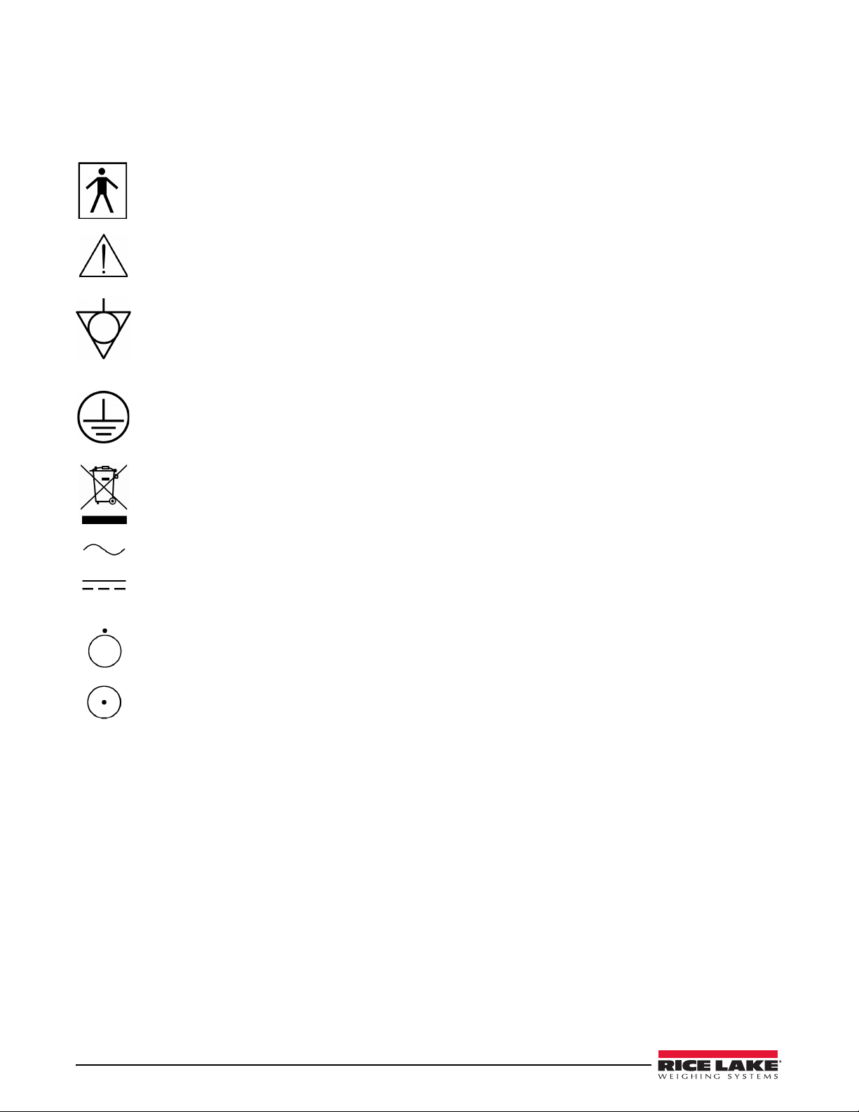
1.3 Safety and Information Symbols
The International Electro-technical Commission (IEC) has established a set of symbols for medical electrical
equipment, which classify a connection or warning any potential hazard.
The classification of symbols is as follows.
Isolated patient connection (IEC 60601-1-1:1995 Type BF (Body Protected))
This means that the input connectors are sui
connection to the heart.
This symbol identifies a safety note. Make sure you understand the function of the device before using. This
symbol is described in appropriate operating manual where it is necessary
safety is involved.
Identifies equipotential ground (IEC 417-5021). This symbol is used in applications where it is important to
indicate to the operator that two or more
functional purposes than for safety purposes the protective conductor terminal is placed at the device earthlings
point.
This symbol is an inside system. It identifies the point where the safety ground of the system is fastened to the
chassis.
Waste Electrical and Electronic Equipment (WEEE). The device could be sent back to the manufacturer for
recycling or proper disposal after their useful lives
national laws after their useful lives.
table for connection to humans provided there is no direct electrical
to follow specified instructions and
accessible functional earth terminals or points are equipotent. More for
. Alternatively the device shall be disposed in accordance with
Alternating current
Direct current
OFF (only for a part of the equipment).
ON (only for a part of the equipment).
4 Competitor Series Installation & Operation Manual
Page 9
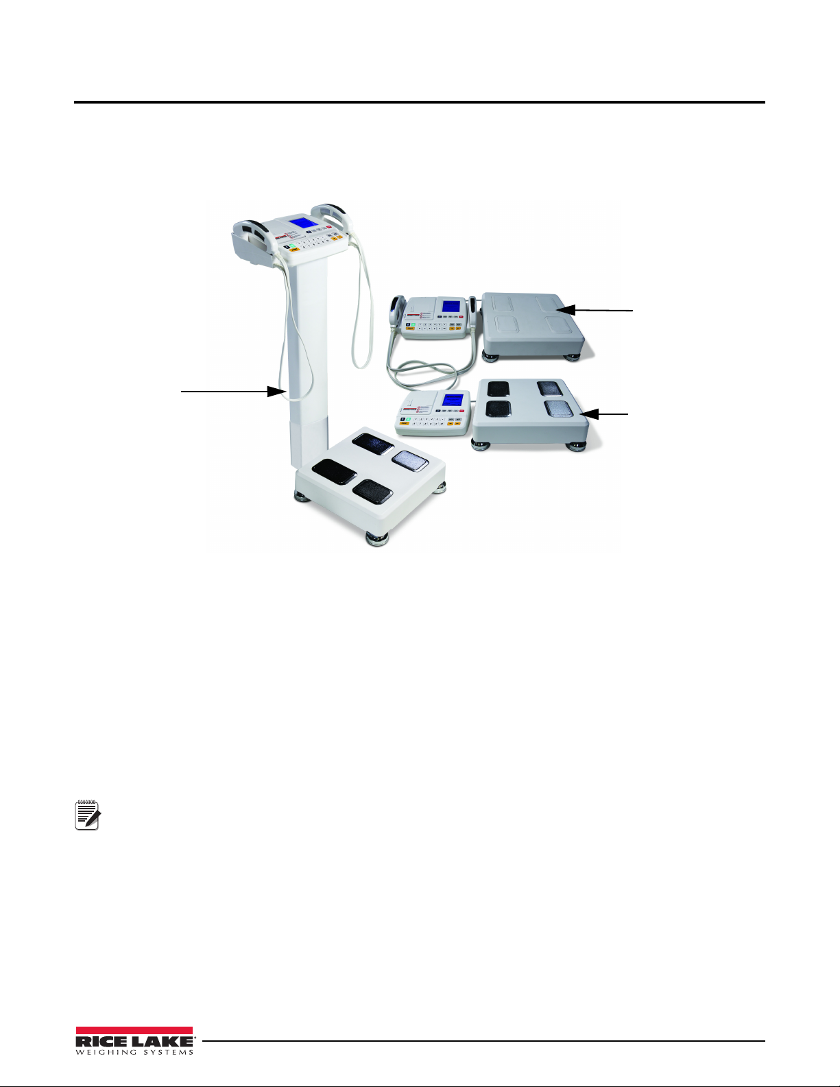
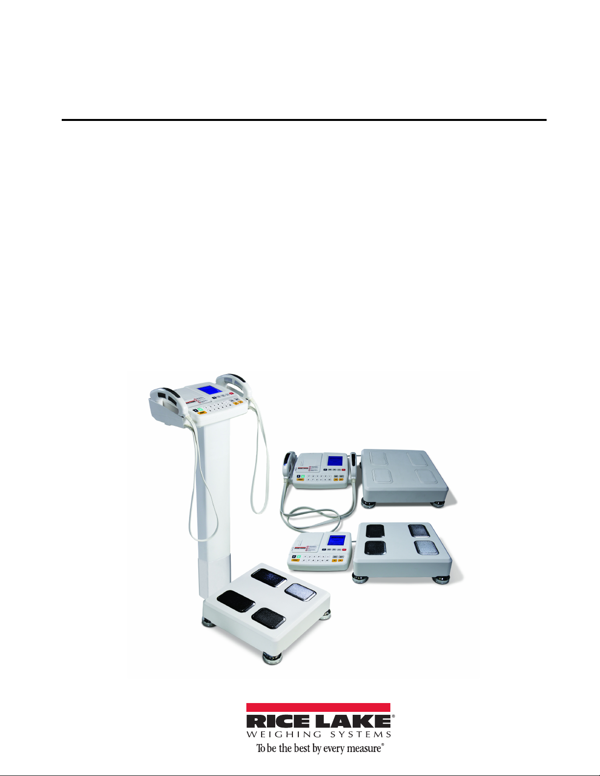
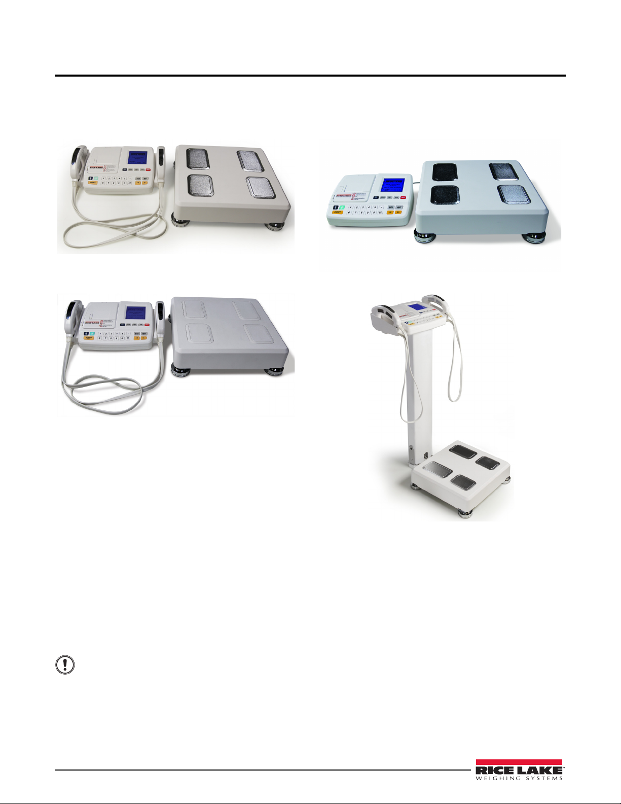
2.0 Introduction
Model D1000-2
Hand to Hand
Model D1000-1 Foot
to Foot
Model D1000-3 Full
Body w/ optional
column shown
Note
The Competitor Series comes in three models:
• D1000-3, Full Body
• D1000-2, Hand to Hand
• D1000-1, Foot to Foot
The Competitor Series is a body scanning device that measures the impedance of the human body by Bioelectrical Impedance Analysis (B.I.A.). Using the impedance value and personal data (height, age, gender, weight), it provides:
•Mass of body fat — Weight
• Lean body mass — L.B.M.
• Total body water — T.B.W.
• Intra-cellular water — I.C.W.
• Extra-cellular water — E.C.W.
• Body mass index — B.M.I.
• Percent of body fat — P.B.F.
• Basal metabolic rate — B.M.R.
• Segmental lean body mass of five body parts (trunk, right arm, left arm, right leg, and left leg).
The B.I.A. method is a way to analyze body composition by measuring the resistance generated from the
human body when harmless alternating current flows through the body. It can be used not only to diagnose
obesity but also to prevent secondary diseases caused by obesity.
The Competitor Series measures body resistance with a tetra-polar electrode technique. With the touch
type electrode, body resistance can be measured by holding the electrode, stepping on the electrode or
touching the ankle.
This applies only to the full body model (D1000-3) of the Competitor Series and is shown in
Figure 2-1 on page 6.
Competitor Series Installation & Operation Manual — Introduction 5
Page 10
2.1 About Body Composition
Segmental Analysis
l
Analysi
y
Lt
Over
Over
Over
Over
Over
Lt
Rt
Rt
Optimal
Optimal
Optimal
Optimal
Optimal
Under Under
Under
UnderUnder
In physical fitness, body composition is used to describe the percentages of fat, bone and muscle in human bodies.
Because muscular tissue takes up less space in our body than fat tissue, our body composition, as well as our
weight, determines how lean our body is. Two people of equal height and body weight may look completely
different from each other because they have a different body composition.
The following points describe things about body
explained in further detail below.
• Body Composition
• Obesity
• Necessity of Body Composition Analysis
• Waist to hip ratio
Body Composition
The human body consists of body fat and lean body. Lean body means non-fat constituents of the human body like
body water, muscles, and bones.
Body water is divided into intra- and extra-cellular water and the ratio between them
within a certain range. Body fat is piled beneath the skin and between abdominal organs. Body fat is hydrolyzed to
make energy needed for normal physiological functions when energy supplies through food intake is not sufficient,
but excessive fat in the body itself is a kind of disease and causes lifestyle diseases.
Healthy people maintain the balance of
body composition in a steady proportion but unhealthy people fail to keep
this balance. When the balance in body composition is broken, diseases like obesity, malnutrition, osteoporosis,
etc. can occur.
Obesity
Various methods can be used to assess obesity but the key factor in obesity assessment is the amount of fat
accumulated in the body.
In general, obesity is defined as the state of not only excess
also excessive body fat compared with weight (invisible or visible obesity).
Strictly speaking obesity is the
state that body fat occupies considerably high ratio to weight.
composition, its makeup and about the measuring process and are
is controlled and maintained
ive weight compared with height (visible obesity) but
Necessity of Body Composition Analysis
Body Composition Analysis is a good indicator to find possible health problems. Body composition analysis
enables professionals to find obesity or an imbalance in body composition at early stages and helps subjects keep
their body healthy. The Competitor Series is a useful preventive diagnostic device.
Waist to Hip Ratio
Waist to hip ratio (W.H.R.) shows the distribution of fat stored in one’s abdomen and hips. It is simple but useful to
assess body fat distribution. Body fat is stored in two distinct ways. They are often called 'apple' and 'pear' type.
Apple type shows bigger girth of waist than hip and pear type has bigger girth of hip than waist. If body fat in the
abdomen increases more, the risk to cardiovascular diseases, diabetes, etc. becomes higher.
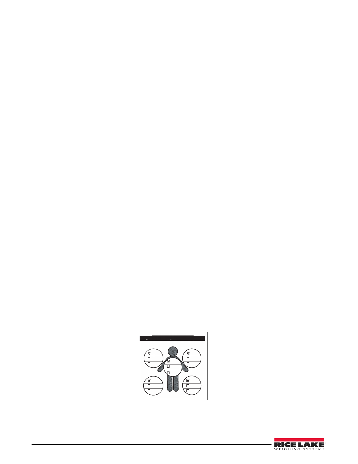
Segmental Analysis
This device analyzes lean body mass of five body parts; trunk, right arm, left arm, right leg, and left leg. This
function can be used as an assessment tool to evaluate the result of exercise or rehabilitation treatment. Segmental
analysis is available only in the full body model (D-1000-3) and is illustrated in the printout shown in Figure 2-1
nta
Figure 2-1. Printout Display of Segmental Analysis
6 Competitor Series Installation & Operation Manual
s
.
Page 11
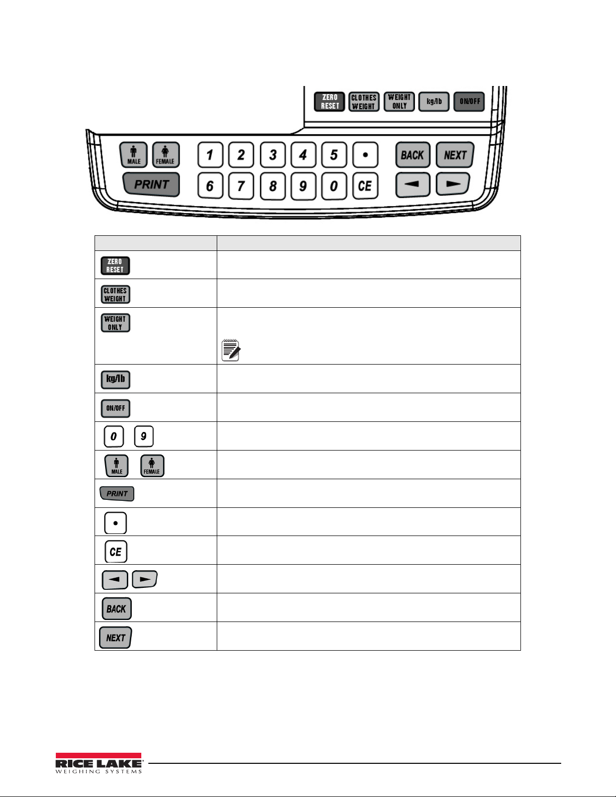
2.2 Keypad Functions
Note
.
Key Description
Adjusts the scale to 0
The user can input the weight of clothes. 0-9.9 lb (0-5.5 kg)
Allows the device to operate in scale mode. Press the button for two
seconds and it will display BCA or SCALE on the display screen.
If clothing weight is already entered, that weight will
automatically be deducted from the total
weight.
Toggles between kilograms and pounds. Press and hold to toggle between
the two and wait for a chime to signal the switch.
Used to turn the scale ON or OFF.
Numeric keys used to enter values.
Used to select gender.
Prints a ticket and will reprint another ticket when in BCA mode.
Decimal
Clear key when entering a numeric value.
Allows for additional menu navigation when in the setup menu and can be
used to switch from male to female.
Used to exit out of a selected setup menu option or exit out of system setup
menu.
Used to store a selected value.
Table 2-1. Keypad Functions
Competitor Series Installation & Operation Manual — Introduction 7
Page 12
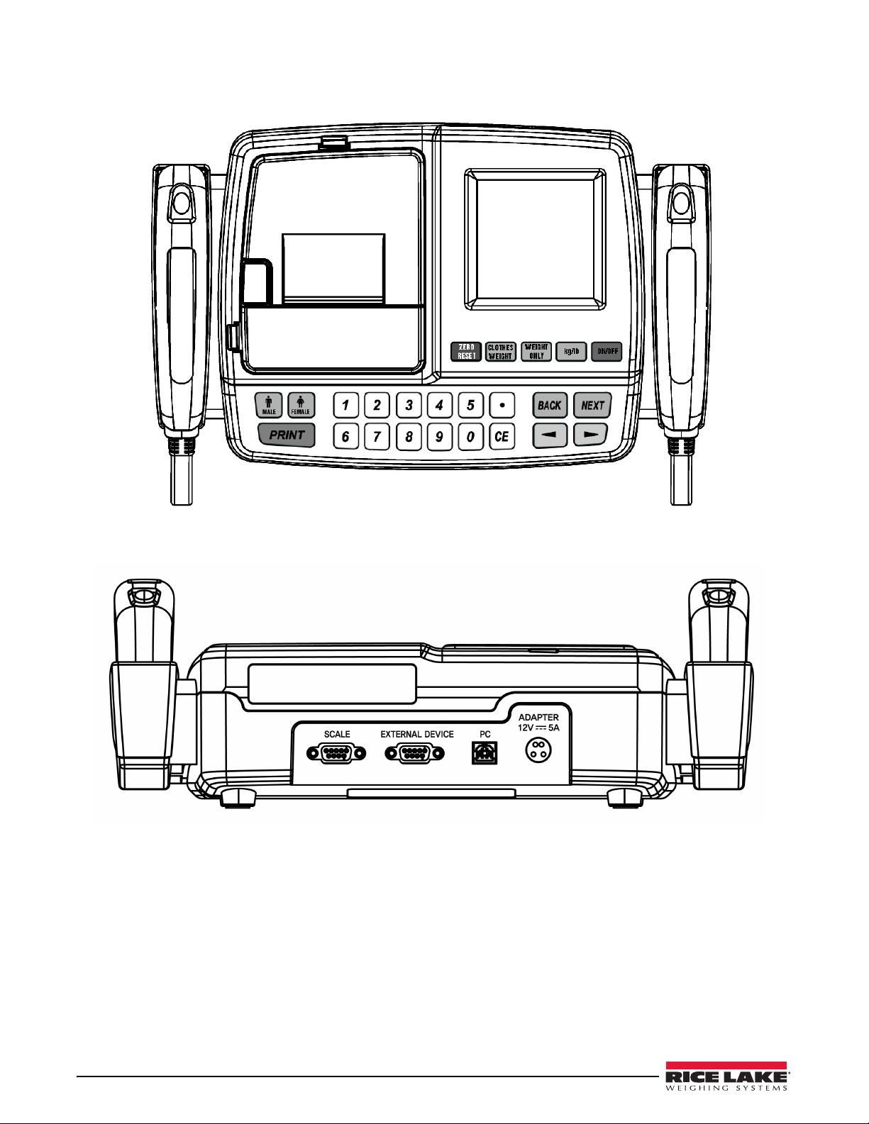
2.3 Digital Display
Figure 2-2. Top View of the Digital Display (Shown with Hand Electrodes)
Figure 2-3. Back of Digital Display Unit
8 Competitor Series Installation & Operation Manual
Page 13
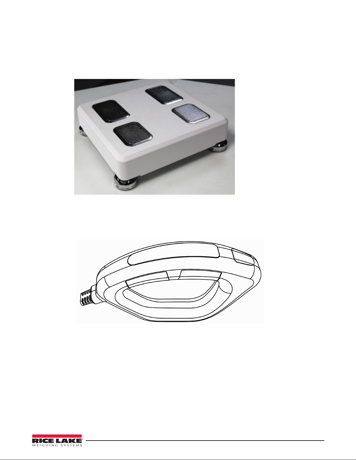
2.4 Scale Base
The scale base consists of:
• Scale base consisting of four plate electrodes that mea
impedance which is how fast electrical ohms travel through the body. This scale base is only available in
the D1000-3 (Full Body) and D1000-1 (Foot to Foot) models.
Figure 2-4. Scale Base (Shown D1000-3 and D1000-1 Models)
sures weight. The plate electrodes measure
2.5 Handle Electrode
The handle electrode is a hand held device that measures the impedance of the body by flowing low levels of
electric current.
Figure 2-5. Handle Electrode
Competitor Series Installation & Operation Manual — Introduction 9
Page 14
3.0 Installation and Setup
Important
3.1 Unpacking
The Competitor Series comes with the following components depending on which model is purchased.
D1000-3 Full Body scale base and digital display
D1000-2 Hand to Hand held display
D1000-1 Foot to Foot
Optional Column
Immediately after unpacking, visually inspect the Competitor Series scale to ensure all components are included
and undamaged. The shipping carton should contain the scale base, hand held display, and this manual. If any parts
were damaged in shipment, notify Rice Lake Weighing Systems and the shipper immediately and keep the original
packaging material for inspection by the carrier’s representative. It is also helpful in the claim process to take
pictures of the condition of the packaging and damage.
If the Competitor Series scale must be returned for modification
sufficient packing materials. Whenever possible, use the original carton when shipping the scale back.
Damage caused by improper packaging is not covered by the warranty.
10 Competitor Series Installation & Operation Manual
or repair, it must be properly packed with
Page 15
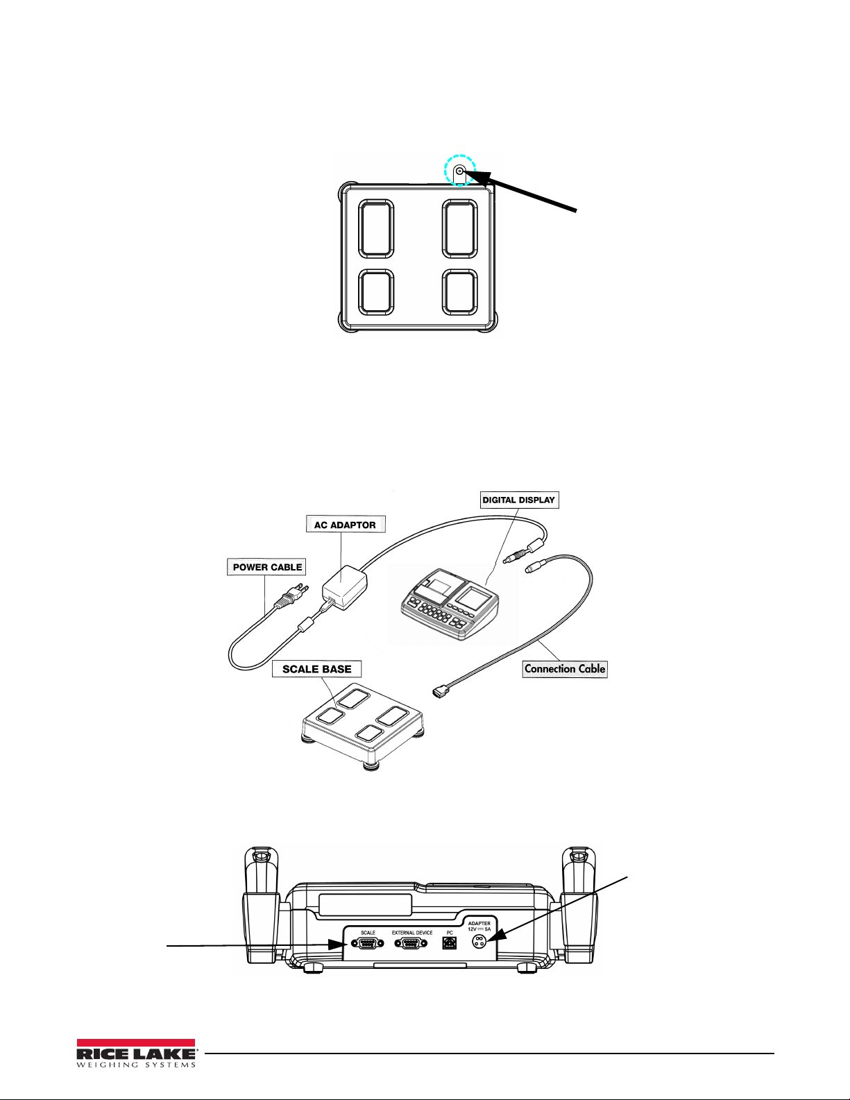
3.2 Scale Base Assembly
12V AC Adapter
Location
DB-9 Connector to
connect display to
scale base
3.2.1 Leveling The Scale Base
Ensure the scale is placed on a flat, level surface. Thin carpeting is acceptable but a hard surface works best. Turn
the feet in or out until the scale level bubble is centered in the middle of the circle.
Figure 3-1. Center Leveling Bubble
3.3 Digital Display
Place the digital display on a table or other sturdy surface.
If connecting the digital display to the optional column, see Section 3.8 on page 13 to view assembly instructions.
3.4 Power Supply Connections
Refer to Figure 3-2 to connect the power supply to the Competitor Series scale.
Connect the 12V AC adapter to the adapter port placed on the rear panel of the digital display. After the cable is
connected press the
Figure 3-2. Competitor Series Component Parts
ON/OFF button on the keypad.
Figure 3-3. Digital Display Connections on the Back
Competitor Series Installation & Operation Manual — Installation and Setup 11
Page 16

3.5 Connecting the Digital Display to the Scale Base
Press the jam
button located
inside the printer.
Connect the digital display to the scale base using the supplied DB-9 connector. Connect the six foot length of
cable into the back of the scale base labeled “Scale” on the back of the unit as shown in Figure 3-3 on page 11.
3.6 Replacing Thermal Printer Paper
Use the following steps to replace the thermal printer paper in the digital display unit. Replacement thermal printer
paper (Rice Lake part number 75947) can be purchased by going to www.ricelakehealth.com..
Figure 3-4. Replacing Thermal Paper in Printer Unit
1. Replace thermal paper while the power is on.
2. Pull the Top button up. Then press the Side b
utton. Open the upper printer cover.
3. Put the roller into the center hole of the thermal paper.
4. Insert the thermal paper with the roller into the
holder as shown in the picture.
5. Take the edge of the paper out and pull paper past the cover.
6. Close the cover.
7. It automatically cuts the paper.
3.7 Jammed Printer Paper Removal
Use the following steps if the printer paper gets jammed in the unit.
1. If the thermal paper gets jammed pull the
button located inside the printer.
2. Remove the jammed paper.
lower printer cover up as shown in Figure 3-5 and press the Jam
12 Competitor Series Installation & Operation Manual
Figure 3-5. Jammed Printer Paper Removal
Page 17

3.8 Optional Column Installation
Note
The Competitor Series scale has an optional column that can be purchased. Use the following steps to install the
optional column.
It is recommended using two people to install the optional column.
1. Use the component parts shown in Figure 3-6.
Figure 3-6. Optional Column Components
Key Number Description (quantity)
1 Digital display (1)
2 Digital display mounting bracket (1)
3 AC adaptor (1)
4 Optional column (1)
5 Scale base (1)
6 M6 Socket head cap screw and washer (4)
7 Cap screw, heck socket flat w/ countersunk head (4)
8 Machine screw, pan head 6
9 Column cover assembly (1)
10 Allen wrench, 4mm (1)
11 Allen wrench, 5mm (1)
12 DB-9 cable (1)
-32 x 5/8 (4)
Table 3-1. Optional Column Assembly Parts
2. Fasten the DB-9 scale base cable as shown in Figure 3-7
Figure 3-7. Fasten Weight Scale Cables
Competitor Series Installation & Operation Manual — Installation and Setup 13
Page 18

3. Assemble the mounting bracket by aligning the bolt holes located at the bottom of the weight scale and
using a 5 mm Allen wrench (provided).
Figure 3-8. Attach Mounting Bracket
4. Attach the digital display to the column using a screwdriver to attach the display with four bolts as shown
on the left hand side of Figure 3-9.
Figure 3-9. Column Attachment
5. Place the scale base on a flat and level surface.
6. Insert the column into the bracket, making sure
that the cable is out of the column as shown in the center
illustration of Figure 3-9.
7. Insert plate bolts into the holes as shown in the right hand picture of Figure 3-9. Fasten the bolts using a 4
mm Allen wrench (included).
14 Competitor Series Installation & Operation Manual
Page 19

3.9 Column Cover Assembly
Note
CAUTION
Insert the column cover as shown in Figure 3-10.
Figure 3-10. Column Cover Assembly
3.10 Connect Power Supply and Scale Cable
Connect the scale cable to the scale port located on the back of the digital display by fastening the DB-9 cable
bolts.
Connect the adapter cable to the adapter port an
d plug the power cord into the power outlet.
This scale should be powered with only the adapter
Be careful not to touch the scale base part of the scale when the power switch is turned ON.
Figure 3-11. Power Supply and Scale Cable Connection Locations
Before connecting a peripheral device to this scale, the power should be turned off, otherwise the scale
could malfunction or be damaged due to electric shock.
Power should be supplied from this device to ensure
and cable that are supplied with this product.
The scale zeros on power up. For accurate readings, press
Competitor Series Installation & Operation Manual — Installation and Setup 15
safe operation and durable performance.
the zero reset button on the digital display.
Page 20

4.0 Configuration
SYSTEM SETUP
DATE/TIME
VOLUME
CONTRAST
BACKLIGHT
ABDOMINAL
KEY SOUND
DATE TYPE
Power On-Off
Main Screen
System Setup
0 to 6
Day
Year
Minute
Hour
Month
TIME/DATE
VOLUME CONTRAST
BACKLIGHT
ABDOMINAL
KEY SOUND
DATE TYPE
THERMAL
PRINTER
THERM LOGOGOAL SETTER
WRESTLER
MODE
START MODE
-3 to 3 -3 to 3 Yes
No
Electronic
Voice
yy-mm-dd
mm-dd-yy
dd-mm-yy
OUTPUT
Off
Auto
Manual
PRINT TYPE
Horizontal
Vertical
On
Off
On
Off
Off
High School
College
Auto
Manual
The Competitor Series scale setup allows users to change the setting of the operational parameters.
4.1 Entering System Setup
To enter the System setup, use the following steps.
1. Turn the unit on by pressing the
2. Press the left arrow (
) button, the 1, 2, 3, 4 buttons and finally the right arrow () button in sequence to
enter SYSTEM SETUP screen.
4.1.1 Navigating Through the Menu Options in SYSTEM SETUP
Use the following keypress options to navigate through the system setup menu.
ON/OFF button.
Figure 4-1. System Setup Main Screen
Press the
the selected system setup menu option. A chime will ring when the selection has been accepted.
4.1.2 Menu in System Setup
The function of each menu item is as follows.
and buttons to scroll through the system setup menu options. Press the NEXT button to enter into
Figure 4-2. System Setup Menu
16 Competitor Series Installation & Operation Manual
Page 21

Parameter Description Choices Steps
DATE/TIME Sets the date and time of the
scale
Date and Time are already
preset from the factory.
Note:
1. If the NEXT button is
pressed before finishing the
setup of date and time, the
date and time inputted at that
time is saved and the System
Setup screen appears. To
cancel any changes
attempted, press the BACK
button. The device will return
to the previous setting and the
System Setup screen will
appear.
2. When body pass plus or
easy body plus is used in data
management, measured date
is automatically saved as the
date set in the device. Date
and time set in the device
should be checked prior to
use.
VOLUME Adjusts the volume of the
voice guidance
CONTRAST Adjusts the brightness of the
display screen
BACKLIGHT Adjusts the backlighting of the
display screen
Year
Month
Day
Hour
Minute
Numeric
0 to 6
Numeric
-3 to 3
Numeric
-3 to 3
Scroll to DATE/TIME by using the left and right
arrows. The date of the device is pre set from the
factory.
1. Press the NEXT button to access DATE/
TIME
2. Change the year by using the left and right
arrows.
3. Press the NEXT button to move to the
month parameter.
4. Change the month by using the left and
right arrows.
5. Press the NEXT button to move to the Day
parameter.
6. Change the day by using the left and right
arrows.
7. Press the NEXT button to move to the Hour
parameter.
8. Change the hour by using the left and right
arrows.
9. Press the NEXT button to move to the
Minute parameter.
10. Change the minute by using the left and
right arrows.
11. Press the NEXT button to save the changes
and a chime will ring when the selection has
been accepted. The screen will exit back to
the System Parameter Setup menu screen.
Scroll to VOLUME by using the left and right arrows.
1. Press the NEXT button to access VOLUME.
2. Use the left and right arrows to increase or
decrease the volume of the unit which
ranges from 0 to 6.
3. Press the NEXT button to save the
changes.
4. Press the BACK button to exit back to the
System Setup menu screen.
Scroll to CONTRAST by using the left and right
arrows.
1. Press the NEXT button to access
CONTRAST.
2. Use the left and right arrows to increase or
decrease the contrast of the unit which
ranges from -3 to 3.
3. Press the NEXT button to save the changes
and a chime rings.
4. Press the BACK button to exit back to the
System Setup menu screen.
Scroll to BACKLIGHT by using the left and right
arrows.
1. Press the NEXT button to access
BACKLIGHT.
2. Use the left and right arrows to increase or
decrease the backlighting of the unit which
ranges from -3 to 3.
3. Press the NEXT button to save the changes
and a chime rings.
4. Press the BACK button to exit back to the
System Setup menu screen.
Table 4-1. System Setup Parameters
Competitor Series Installation & Operation Manual — Configuration 17
Page 22

Parameter Description Choices Steps
ABDOMINAL Sets the analysis of abdominal
fat under 18 years of age
KEY SOUND Sets the sound of keys when
data is entered
DATE TYPE Sets the format of the date yy-mm-dd
THERMAL PRINTER Selects the printing mode of
the thermal printer
Horizontal and vertical print
examples can be seen in
Section 6.8 on page 28.
Yes
No
Electronic
Voice
mm-dd-yy
dd-mm-yy
Output
Print Type
Scroll to ABDOMINAL by using the left and right
arrows.
1. Press the NEXT button to access
ABDOMINAL.
2. Use the left and right arrows to select either
Yes or No.
3. Press the NEXT button to save the changes
and a chime rings.
4. Press the BACK button to exit back to the
System Setup menu screen.
Scroll to KEY SOUND by using the left and right
arrows.
1. Press the NEXT button to access KEY
SOUND.
2. Use the left and right arrows to select either
Elec (electronic sounds) or Voice (human
sounds).
3. Press the NEXT button to save the changes
and a chime rings.
Press the BACK button to exit back to the System
Setup menu screen.
Scroll to DATE TYPE by using the left and right
arrows.
1. Press the NEXT button to access DATE
TYPE.
2. Use the left and right arrows to select the
desired date type.
3. Press the NEXT button to save the changes
and a chime rings.
Press the BACK button to exit back to the System
Setup menu screen.
Scroll to THERMAL PRINT by using the left and right
arrows.
1. Press the NEXT button to access
THERMAL PRINT.
2. Press the 1 button to access the Output
type.
3. Use the left and right arrows to select either
Auto, Manual, or Off.
• Auto means that a print ticket
automatically prints.
• Manual requires you to press the Print
button at the end of a weighment.
• Off means that nothing will print.
4. Press the 2 button to access the Print Type.
5. Use the left and right arrows to select either
Horizontal print or Vertical print.
6. Press the NEXT button to save the changes
and a chime rings.
Press the BACK button to exit back to the System
Setup menu screen.
Table 4-1. System Setup Parameters
18 Competitor Series Installation & Operation Manual
Page 23

Parameter Description Choices Steps
THERM LOGO Thermal logo can be used but
requires a PC with optional
Body Pass software.
GOAL SETTER Can be set from 3 — 30%. On
WRESTLER MODE This mode provides weight,
mass of fat body and lean
body mass to maintain the
minimum P.B.F.
START
MEASUREMENT
MODE
Selects the start mode Auto
On
Off
Off
Off
High School
College
Manual
Scroll to THERM LOGO by using the left and right
arrows.
1. Press the NEXT button to access THERM
LOGO.
2. Use the left and right arrows to select either
On or Off.
3. Press the NEXT button to save the changes
and a chime rings.
Press the BACK button to exit back to the System
Setup menu screen.
Scroll to GOAL SETTER by using the left and right
arrows.
1. Press the NEXT button to access GOAL
SETTER.
2. Use the left and right arrows to select either
On or Off.
3. Press the NEXT button to save the changes
and a chime rings.
Press the BACK button to exit back to the System
Setup menu screen.
Scroll to WRESTLER MODE by using the left and
right arrows.
1. Press the NEXT button to access
WRESTLER MODE.
2. Use the left and right arrows to select either
Off, High School or College.
3. Press the NEXT button to save the changes
and a chime rings.
Press the BACK button to exit back to the System
Setup menu screen.
Scroll to START MODE by using the left and right
arrows.
1. Press the NEXT button to access START
MODE.
2. Use the left and right arrows to select either
Auto or Manual.
3. Press the NEXT button to save the changes
and a chime rings.
Press the BACK button to exit back to the System
Setup menu screen.
Table 4-1. System Setup Parameters
Competitor Series Installation & Operation Manual — Configuration 19
Page 24

5.0 Measurement and Analysis
5.1 Suggestions for Accurate and Repeatable Results
For best results, the reliability of the results can be assessed by its accuracy. The “Accuracy” of the device is
determined by comparing the actual body composition and the results from the Competitor Series. The
repeatability and reliability is determined when the device gives the identical results under the same condition. In
order to maintain the accuracy of the results, the following guidelines should be used.
• Measure on an empty stomach as water volume increases after a meal.
• Measure three to four hours after a meal.
• Avoid beverages containing caffeine or beverages that function as a diuretic four hours before the
measurement.
• Drink two cups of water two hours before the measurement.
• Before the measurement, the subject should be in a stable condition.
• Measure three to four hours after a bath, a sauna, exercise or any other activity that causes the person to
sweat a lot.
• Avoid drinking alcohol 24 hours before the measurement.
• Wear clothes as light as possible.
• Once the subject is on the scale, avoid sudden movement from sitting to standing position. Body fluid goes
down to the lower body and it can affect the results. Thus subjects should be measured after maintaining
standing position for five minutes.
• Clean both the electrodes and measuring body parts.
• Changes in room temperature may affect the results. Measurement should be done in a temperature around
68°F (20°C).
• Body composition and weight varies even during the day. Therefore, the measurement should be
performed at the same time every day. For a person who stands for a long period of time during the day, it
is advised to measure in the morning.
• Go to the bathroom before measurement.
• Maintain correct position and posture during the measurement.
• Poor contact between the feet (which should be free of dirt), and electrodes can produce an error message.
Heels of the feet should be placed directly on top of the rear electrodes while the front part of the foots
needs to be in contact with the front of the electrodes.
• If there are calluses on the soles of the feet, or an individual is wearing thin nylons, accurate measurement
may still be possible.
• Keep electrodes clean by wiping them with a disinfectant.
• Wrestlers should confirm proper hydration before assessing body fat percent and weight.
• When interpreting the results, the data provided by the Competitor Series, as well as any supplementary
information such as diet or exercise programs based on this data, should be interpreted by a licensed
professional.
In order to keep one's health and the balance of body composition, check the changes of body composition through
the continuous analysis and compare the results. Make sure that the body composition should be measured under
the same physical and environmental conditions. If the condition before the measurement such as consumption of a
meal, meal time, and activities (exercise, sauna, drinking lots of beverage, urination, etc.) are kept same, the
reproducibility of a device is obtained. Therefore, the data can be used to evaluate the change of body composition.
20 Competitor Series Installation & Operation Manual
Page 25

5.2 Correct Posture
Note
To get the most accurate weight, there are certain steps that should be taken. The following sections show the
correct way to touch the plate electrodes and how to touch the handle electrodes.
5.2.1 How to Touch Plate Electrodes on the Scale Base
• Make sure that the plate electrodes are clean.
• Stand on plate electrodes with bare feet, no socks.
• Remove sweat or foreign matter from the
• Place the bare feet squarely on the plate electrodes. Make sure
of the feet and the plate electrodes.
Figure 5-1. Correct Stance on Scale Base
5.2.2 How to Touch Handle Electrodes
• Grip the handle electrodes with fingers and palms.
• Four electrodes should be touched impartially.
• Stretch both arms and spread them 30° from the body.
soles of the feet.
that clothing items are not between the soles
Figure 5-2. Handling the Electrodes
Not touching all of the electrodes sufficiently will affect the reliability of your results. When a person has small hands or
feet and cannot cover all electrodes sufficiently, try to distribute as evenly as possible to touch all the electrodes equally.
During the measurement, the patient should not be tou
If all eight electrodes are not perfectly touched during measurement, measurement will be stopped or
reliable.
Competitor Series Installation & Operation Manual — Measurement and Analysis 21
ched by others or any other conductive materials.
the result will not be
Page 26

5.3 Measuring Posture
• Step on the scale with bare feet. Stretch both arms and spread them 40° from the body.
• Do not speak or move the body until the measurement is completed.
• Do not bend or shake the arms until the
• The measurement will be stopped if all eight electr
measurement is completed.
odes are not equally touched.
Figure 5-3. Measuring Posture - left figure shows measuring posture for the whole and upper body while right figure shows
posture for the lower body.
22 Competitor Series Installation & Operation Manual
Page 27

5.4 Body Composition Weighing Measurement
Body Composition
Analyzer
Step on scale to Activate
CLOTHES
0.0
BCA lb
SCALE
BCA
CLOTHES
0.0
Lb
1. Turn the Competitor Series on by pressing the ON/OFF key. The following screen is displayed.
Figure 5-4. Body Composition Analyzer Main Screen
2. Select the BCA button to measure the body composition of the person. This will toggle the main screen
between Scale and BCA (Body Composition Analyzer)
Deduct the Weight of Clothing.
The weight of clothing can be deducted prior to using the Competitor Series scale. To deduct (or tare off the
weight) of your clothing prior to using the Competitor Series use the following steps.
1. Press and hold the
2. Press the
screen appears on the display.
3. Use the numbered buttons to enter the clothing weight until the desired amount is entered.
4. Press the
has been accepted.
5. Now step on the scale, the scree
• Do not move or speak until the wei
• The measured weight is dis
• The measuring range is 22.0 to 440.9 lb (10 - 200 kg).
6. A
fter the weight measurement, continue to input the personal data.
CLOTHES WEIGHT button and hold for approximately four to five seconds and the following
NEXT button to save that weight value and you will hear a chime stating that the entered weight
ON/OFF button to power up the unit.
Figure 5-5. Enter Clothes Weight
n changes with a chime bell.
ght measurement is completed.
played on the screen.
Competitor Series Installation & Operation Manual — Measurement and Analysis 23
Page 28

7. Personal information — Input the following information in order; gender, age, and height. Confirm the
input data. Press
• Select gender — The following message appears,
using the male or female icon buttons located on the left side of the unit. Press the
• Input age — The following message appears,
on the keypad. The possible input range is 7 to 89 years old. Press the
• Input height — The following mes
keypad. The possible input range 39.4 to 78.7 inches. Press the
NEXT button to move to the next step.
Choose your gender. Select either male or female
NEXT button.
Input your age. Input the age using the numerical buttons
NEXT button.
sage appears, Input your height. Input the height using the numeric
NEXT button.
8. Measurement Posture
Once the input is completed, the screen shown in Figure 5-6 appears in the display screen.
Figure 5-6. Measurement
• Hold the electrodes and stand straight as the unit starts measuring impedance. Do not move, speak, or
bend arms during the measurement. Measuring time takes under one minute.
• During the measurement, the following screen
Figure 5-7. Measuring Screen
appears and begins counting down.
24 Competitor Series Installation & Operation Manual
Page 29

9. Result screen
Note
• After the measurement is completed, the result is displayed on the screen.
Figure 5-8. Result Screen
• The results are presented in graph and numerical values.
• Check the results and press the
PRINT (Auto Print must be on) or NEXT button to exit and clear off the
scale
10. Print results and restart
• Once the result is displayed it can be printed
out. After confirming the result, press the NEXT button if
you want to measure again.
• The Competitor Series returns back
If Automatic printing is selected during the system setup, the result sheet is automatically printed after
measurement. If the Print button is pressed, the
to the initial start up screen after one minute.
same results can be printed again.
Competitor Series Installation & Operation Manual — Measurement and Analysis 25
Page 30

6.0 Interpreting the Results
l
Analysi
y
There are various ways to interpret the criteria of the printed results.
6.1 Personal Data
The subject's date, height, weight, age and gender are indicated on the result sheet.
6.2 Segmental Analysis
Soft lean mass and body fat of five body parts (left and right arms, left and right legs, and trunk) are indicated in
Figure 6-1.
Segmental Analysis
nta
s
Lt
Over
Optimal
Lt
Over
Optimal
Under Under
Over
Optimal
Under
Over
Optimal
UnderUnder
Over
Optimal
Rt
Rt
Figure 6-1. Segmental Analysis Ticket Printout
6.3 Body Composition
Human body is mainly divided into body fat and lean body mass. Lean body mass is the sum of non-fat
constituents like muscle, bone, body water, etc. Body water consists of intra- and extra-cellular water.
A body composition table provides the sub
body fat, lean body mass, and intra- and extra-cellular water based on standard weight. Figures 6-3 through 6-9
show examples on print tickets of what the body composition of an individual is.
• Body Weight = Lean Body Mass + Mass of Body Fat
• Lean Body Mass = Total Body Water + other non-fat elements of body
• Total Body Water = Extra Cellular Water + Intra Cellular Water
• Weight: subject’s actual body weight —Std. wt. (S
• L.B.M. (Lean Body Mass): Subtract body fat mass from body weight.
• M.B.F. (Mass of Body Fat): It is the total body fat mass in
• T.B.W. (Total Body Water): It is the total body water.
• I.C.W. (Intra-Cellular Water): It exists
• E.C.W. (Extra-Cellular Water): It exists outside of
ject's actual body composition and the optimal range of body weight,
tandard weight): Height (m2) × 22 (ideal BMI value)
the unit of lb.
inside of cell membrane.
cell membrane like plasma, interstitial fluid, etc.
Not only the measured data but also the eval
uation and the optimal range based on standard weight are presented.
For example,
Weight / Over
135.5
[108.9~132.9]
26 Competitor Series Installation & Operation Manual
Weight: It is one of the items in body composition
Over: It is the evaluation of the subjec
t’s state based on standard weight.
135.5: It is the measured value of the subject’
[108.9~132.9]: It is the optimal range based on standard weight.
table.
s body composition.
Page 31

6.4 Basal Metabolic Rate (B.M.R.)
Note
B.M.R. is the calories to maintain human body's basic function such as movement of heart, brain, neural
transmission, regulating body temperature and so on. B.M.R. is in proportion to S.L.M. because body fat stores
energy while muscle consumes energy. Therefore, even if the weight is same between persons, the person with
more muscle has greater B.M.R. The B.M.R. is shown in the Body Composition table on printed tickets.
Figure 6-2. Basal Metabolic Rate Location on Print Tickets
6.5 Body Type
Body type is determined by B.M.I and P.B.F. Body type is classified into 9 types; Low fat Low weight, Low fat
Muscular, Athletic, Low weight, Standard, Over Weight Muscular, Thin fat, Over fat, Obese. It is illustrated on
printed tickets shown in Figures 6-3 through 6-9.
6.6 E.C.W./T.B.W. Ratio
It indicates the ratio between extra-cellular water and total body water. If the value is 'Over' in the pie chart, it
means that the balance of body water is broken. If this imbalance is not temporary, it is recommended to consult
with a doctor.
6.7 Wrestler Mode
It provides Weight, Mass of Fat Body and Lean Body Mass to maintain the minimum P.B.F.
For people choosing the ‘high school’,
For people choosing the ‘college’, th
1. Minimum weight: Weight to mai
*Min Weight = LBM / 0.93: Minimum PBF(%) is 7%.
LBM / 0.95 : Minimum PBF(%) is 5%.
2. Mass of Body Fat: M.B.F to maintain the minimum
* Fat Mass = MBF – (Current weight – Minimum weight)
3. Lean Body Mass: It indicates the current Lean Body Mass.
* LBM = Current Lean Body Mass
The equation for minimum weight follows guidelines of the Weight Management from NCAA (National
Collegiate Athletic Association) issued in 1996.
Examples of Wrestler Mode are shown on the following pages in Figures 6-3 through 6-9 and only if Wrestler
Mode is turned on.
the minimum P.B.F is 7%.
e minimum P.B.F is 5%.
ntain the minimum Body fat %.
Body Fat %.
Competitor Series Installation & Operation Manual — Interpreting the Results 27
Page 32

6.8 Sample Print Tickets
B.M.I.
P.B.F.
WEIGHT
L.B.M.
T.B.W.
I.C.W.
E.C.W.
Body Fat
STD.WT.
Impedance
W.H.R.
B.M.R.
H EIGHT
AGE
GENDER
TIME
DATE
05.09.14
09:16:15
45
Female
yrs
ft in
lb
lb
lb
lb
lb
lb
lb
kcal
kg/m
2
%
%
lb
lb
lb
5
5
05.0
166.2
111. 8
80. 4
53. 3
27. 1
54. 4
27. 7
32. 8
132. 2
1242
432
117. 6
111. 8
5. 8
Fat Mass
L.B.M.
Wrestler Mode
TARGET P.B.F.
Min Weight
B.M.I.
P.B.F.
WEIGHT
L.B.M.
T.B.W.
I.C.W.
E.C.W.
Body Fat
STD.WT.
Impedance
W.H.R.
B.M.R.
H EIGHT
AGE
GENDER
TIME
DATE
05. 09.1 4
09: 23:1 6
45
Female
yrs
ft in
lb
lb
lb
lb
lb
lb
lb
kcal
kg/m
2
%
%
lb
lb
lb
7
5
05.0
166.2
112. 0
80. 6
53. 5
27. 1
54. 2
27. 7
32. 6
132. 2
1243
429
120. 4
112. 0
8. 4
Fat Mass
L.B.M.
Wrestler Mode
TARGET P.B.F.
Min Weight
B.M.I.
P.B.F.
WEIGHT
L.B.M.
T.B.W.
I.C.W.
E.C.W.
Body Fat
STD.WT.
Impedance
W.H.R.
B.M.R.
H EIGHT
AGE
GENDER
TIME
DATE
05.09.14
09:30:27
45
Female
yrs
ft in
lb
lb
lb
lb
lb
lb
lb
kcal
kg/m
2
%
%
lb
lb
lb
20
5
05.0
166.2
111. 8
80. 4
53. 3
27. 1
54. 4
27. 7
32. 8
132. 2
1242
431
139. 7
26. 5
27. 9
Fat Mass
L.B.M.
Goal Setter
TARGET P.B.F.
Min Weight
B.M.I.
P.B.F.
WEIGHT
L.B.M.
T.B.W.
I.C.W.
E.C.W.
Body Fat
STD.WT.
Impedance
W.H.R.
B.M.R.
H EIGHT
AGE
GENDER
TIME
DATE
05. 09. 14
09:36:37
45
Female
yrs
ft in
lb
lb
lb
lb
lb
lb
lb
kcal
kg/m
2
%
5
05.0
166.2
111. 6
80. 2
53. 1
27. 1
54. 6
27. 7
32. 9
132. 2
1241
436
Vertical example with goal setter off and
wrestling mode on with college values
Vertical example with goal setter off and
wrestling mode on with high school values
Vertical example with goal setter on and
wrestling mode turned off
Vertical example with goal setter off and
wrestling mode off
Tickets can be set up in a variety of ways depending on what features you want to be displayed on the ticket. The
following examples on pages 28 through 36 illustrate the different configurations that can be shown.
6.8.1 Hand to Hand Example Print Tickets
28 Competitor Series Installation & Operation Manual
Page 33

DATE
TIME
GENDER
yrs
Female
05.09.14
09:09:10
AGE
45
HEIGHT
5 05.0
ft in
ITEM RESULT OPTI MAL RANGE ITEM RESULT OPT IMAL RANGE
WEIGHT
L.B.M.
T.B.W.
I.C.W.
E.C.W.
Body Fat
166.2
112.5
80.9
53.5
27.4
53.7
lb
lb
lb
lb
lb
lb
(
119.0 145.5
)
(
92.5 105.8
)
~
~
(
66.5 76.0
)
~
(
48.0 52.6
)
~
~
(
28.2 32.8
)
(
26.4 39.6
)
~
B.M.I.
P.B.F.
STD.WT.
B.M.R.
Impedance
27.7
32.4
1245
426
132.2
kg/m
2
%
kcal
lb
(
18.5 25.0
)
(
20.0 30.0
)
~
~
TARGET P.B. F .
Min Weight
Fat Mass
L.B.M.
Wrestler Mode
5
118.4
5.9
lb
lb
lb
%
112.5
DATE
TIME
GENDER
yrs
Female
05.09.14
09: 00: 26
AGE
45
HEIGHT
5
05.0
ft in
ITEM RESULT OPTIMAL RANGE
ITEM
RESULT OPTI MAL RANGE
WEIGHT
L.B.M.
T.B.W.
I.C.W.
E.C.W.
Body Fat
166.2
111.4
80.2
53.3
26 .9
54 . 8
lb
lb
lb
lb
lb
lb
(
119.0 145.5
)
(
92.5 105.8
)
~
~
(
66.5 76.0
)
~
(
47.6 52.2
)
~
~
(
27.9 32.6
)
(
26.4 39.6
)
~
B.M.I.
P.B.F.
STD.WT.
B.M.R.
Impedance
27.7
33.0
1240
437
132.2
kg/m
2
%
kcal
lb
(
18.5 25.0
)
(
20.0 30.0
)
~
~
Min Weight
Fat Mass
L.B.M.
Wrestler Mode
TARGET P.B. F.
7
119.7
lb
8.3
lb
lb
114.4
DATE
TIME
GENDER
yrs
Female
05.09 . 14
08: 52: 13
AGE
45
HEIGHT
5
05.0
ft in
ITEM RESULT OPTIMAL RANGE
ITEM
RESULT OPTI MAL RANGE
WEIGHT
L.B.M.
T.B.W.
I.C.W.
E.C.W.
Body Fat
166.2
111.8
80.4
53.3
27 .1
54 . 4
lb
lb
lb
lb
lb
lb
(
119.0 145.5
)
(
92.5 105.8
)
~
~
(
66.5 76.0
)
~
(
47.8 52.4
)
~
~
(
27.9 32.6
)
(
26.4 39.6
)
~
B.M.I.
P.B.F.
STD.WT.
B.M.R.
Impedance
27.7
32. 8
1250
296
132.2
kg/m
2
%
kcal
lb
(
18.5 25.0
)
(
20.0 30.0
)
~
~
Min Weight
Fat Mass
L.B.M.
Goal Setter
TARGET P.B. F.
20
139.7
lb
27.9
lb
lb
26.5
DATE
TIME
GENDER
yrs
Female
05.09.14
08:36:50
AGE
45
HEIGHT
5 05.0
ft in
ITEM RESULT OPTIMAL RANGE ITEM RESULT OPTIMAL RANGE
WEIGHT
L.B.M.
T.B.W.
I.C.W.
E.C.W.
Body Fa t
166.4
112.9
81.3
54.0
27.3
53.5
lb
lb
lb
lb
lb
lb
(
119.0 145.5
)
(
92.5 105.8
)
~
~
(
66.5 76.0
)
~
(
48.2 52.9
)
~
~
(
28.4 33.0
)
(
26.4 39.6
)
~
B.M.I.
P.B.F.
STD.WT.
B.M.R.
Impedance
27.7
32.2
1247
424
132.2
kg/m
2
%
kcal
lb
(
18.5 25.0
)
(
20.0 30.0
)
~
~
Horizontal example with goal setter off and
wrestling mode on with college values
Horizontal example with goal setter off and
wrestling mode on with high school values
Horizontal example with goal setter on and
wrestling mode off
Horizontal example with goal setter off and
wrestling mode off
Competitor Series Installation & Operation Manual — Interpreting the Results 29
Page 34

6.8.2 Foot to Foot Example Print Tickets
B.M.I.
P.B.F.
WEIGHT
L.B.M.
T.B.W.
I.C.W.
E.C.W.
Body Fat
STD.WT.
Impedance
W.H.R.
B.M.R.
H EIGHT
AGE
GENDER
TIME
DATE
12. 03. 13
03:30:02
45
Female
yrs
ft in
lb
lb
lb
lb
lb
lb
lb
kcal
kg/m
2
%
%
lb
lb
lb
5
5
05.0
166.6
111. 6
82. 4
54. 4
28. 0
52. 0
27. 7
31. 2
132. 2
1254
289
117. 6
111. 8
5. 8
Fat Mass
L.B.M.
Wrestler Mode
TARGET P.B.F.
Min Weight
B.M.I.
P.B.F.
WEIGHT
L.B.M.
T.B.W.
I.C.W.
E.C.W.
Body Fat
STD.WT.
Impedance
W.H.R.
B.M.R.
H EIGHT
AGE
GENDER
TIME
DATE
12. 03. 13
03: 37: 11
45
Female
yrs
ft in
lb
lb
lb
lb
lb
lb
lb
kcal
kg/m
2
%
%
lb
lb
lb
7
5
05.0
166.6
114. 6
82. 4
54. 4
28. 0
52. 0
27. 7
31. 2
132. 2
1254
289
123. 2
114. 6
8. 6
Fat Mass
L.B.M.
Wrestler Mode
TARGET P.B.F.
Min Weight
B.M.I.
P.B.F.
WEIGHT
L.B.M.
T.B.W.
I.C.W.
E.C.W.
Body Fat
STD.WT.
Impedance
W.H.R.
B.M.R.
H EIGHT
AGE
GENDER
TIME
DATE
12. 03. 13
03:44:22
45
Female
yrs
ft in
lb
lb
lb
lb
lb
lb
lb
kcal
kg/m
2
%
%
lb
lb
lb
20
5
05.0
166.6
114. 6
82. 4
54. 4
28. 0
52. 0
27. 7
31. 2
132. 2
1254
289
143. 2
23. 4
28. 6
Fat Mass
L.B.M.
Goal Setter
TARGET P.B.F.
Min Weight
B.M.I.
P.B.F.
WEIGHT
L.B.M.
T.B.W.
I.C.W.
E.C.W.
Body Fat
STD.WT.
Impedance
W.H.R.
B.M.R.
H EIGHT
AGE
GENDER
TIME
DATE
12. 03. 13
03:50:21
45
Female
yrs
ft in
lb
lb
lb
lb
lb
lb
lb
kcal
kg/m
2
%
5
05.0
166.6
114. 0
82. 0
54. 2
27. 8
52. 6
27. 7
31. 6
132. 2
1251
293
Vertical example with goal setter off and
wrestling mode on with college values
Vertical example with goal setter off and
wrestling mode on with high school values
Vertical example with goal setter on and
wrestling mode turned off
Vertical example with goal setter off and
wrestling mode off
30 Competitor Series Installation & Operation Manual
Page 35

DATE
TIME
GENDER
yrs
Female
12.03.13
03:23:00
AGE
45
HEIGHT
5 05.0
ft in
ITEM RESULT OPTI MAL RANGE ITEM RESULT OPTIMAL RANGE
WEIGHT
L.B.M.
T.B.W.
I.C.W.
E.C.W.
Body Fat
166.6
114.6
82.4
54.4
28 .0
52 .0
lb
lb
lb
lb
lb
lb
(
119.0 145.5
)
(
92.5 105.8
)
~
~
(
66.5 76.0
)
~
(
48.9 53.5
)
~
~
(
28.8 33.5
)
(
26.4 39.6
)
~
B.M.I.
P.B.F.
STD.WT.
B.M.R.
Impedance
27.7
31.2
1254
289
132.2
kg/m
2
%
kcal
lb
(
18.5 25.0
)
(
20.0 30.0
)
~
~
TARGET P.B. F.
Min Weight
Fat Mass
L.B.M.
Wrestler Mode
5
120.6
6.0
lb
lb
lb
%
114.6
DATE
TIME
GENDER
yrs
Female
08.02. 14
09: 08:59
AGE
45
HEIGHT
5
05.0
ft in
ITEM RESULT OPTIMAL RANGE
ITEM
RESULT OPTIMAL RANGE
WEIGHT
L.B.M.
T.B.W.
I.C.W.
E.C.W.
Body Fat
166.6
114.2
82.2
50.2
32.0
52 .4
lb
lb
lb
lb
lb
lb
(
119.0 145.5
)
(
92.5 105.8
)
~
~
(
66.5 76.0
)
~
(
48.7 53.3
)
~
~
(
28.6 33.2
)
(
26.4 39.6
)
~
B.M.I.
P.B.F.
STD.WT.
B.M.R.
Impedance
27.7
31.5
132.2
1252
382
kg/m
2
%
kcal
lb
(
18.5 25.0
)
(
20.0 30.0
)
~
~
Min Weight
Fat Mass
L.B.M.
Wrestler Mode
TARGET P.B.F.
7
122.7
lb
8.5
lb
lb
114.2
DATE
TIME
GENDER
yrs
Female
12.03. 13
03:06: 11
AGE
45
HEIGHT
5
05.0
ft in
ITEM RESULT OPTIMAL RANGE
ITEM
RESULT OPTIMAL RANGE
WEIGHT
L.B.M.
T.B.W.
I.C.W.
E.C.W.
Body Fat
166.6
113.5
81.7
54.2
27 .5
53 .1
lb
lb
lb
lb
lb
lb
(
119.0 145.5
)
(
92.5 105.8
)
~
~
(
66.5 76.0
)
~
(
48.5 53.3
)
~
~
(
28.4 33.2
)
(
26.4 39.6
)
~
B.M.I.
P.B.F.
STD.WT.
B.M.R.
Impedance
27.7
31. 9
1250
296
132.2
kg/m
2
%
kcal
lb
(
18.5 25.0
)
(
20.0 30.0
)
~
~
Min Weight
Fat Mass
L.B.M.
Goal Setter
TARGET P.B.F.
20
141.8
lb
28.3
lb
lb
24.8
DATE
TIME
GENDER
yrs
Female
12.03 .13
02:50:42
AGE
45
HEIGHT
5 05.0
ft in
ITEM RESULT OPTI MAL RANGE ITEM RESULT OPTIMAL RANGE
WEIGHT
L.B.M.
T.B.W.
I.C.W.
E.C.W.
Body Fat
166.6
112.9
81.3
54.0
27.3
53.7
lb
lb
lb
lb
lb
lb
(
119.0 145.5
)
(
92.5 105.8
)
~
~
(
66.5 76.0
)
~
(
48.2 52.9
)
~
~
(
28.4 33.0
)
(
26.4 39.6
)
~
B.M.I.
P.B.F.
STD.WT.
B.M.R.
Impedance
27.7
32.3
1247
300
132.2
kg/m
2
%
kcal
lb
(
18.5 25.0
)
(
20.0 30.0
)
~
~
Horizontal example with goal setter off and wrestling
mode on with college values
Horizontal example with goal setter off and wrestling
mode on with high school values
Horizontal example with goal setter on and wrestling
mode off
Horizontal example with goal setter off and wrestling
mode off
Competitor Series Installation & Operation Manual — Interpreting the Results 31
Page 36

Segmental Analysis
l
Analy
y
Lt
Over
Lt
Rt
Rt
Optimal
Optimal
Optimal
Optimal
Optimal
Under
Under
Under
Under
Under
Over
Over
Over
Over
B.M.I.
P.B.F.
WEIGHT
L.B.M.
T.B.W.
I.C.W.
E.C.W.
Body Fat
STD.WT.
Impedance
W.H.R.
B.M.R.
H EIGHT
AGE
GENDER
TIME
DATE
05. 09.1 4
09:24:43
45
Female
yrs
ft in
lb
lb
lb
lb
lb
lb
lb
kcal
kg/m
2
%
%
lb
lb
lb
5
5
05.0
166.6
114. 4
82. 4
50. 2
32. 2
52. 2
27. 7
31. 3
0. 82
1253
381
120. 4
114. 4
6. 0
Fat Mass
L.B.M.
Wrestler Mode
TARGET P.B.F.
Min Weight
Ratio of E.C.W./T.B.W
0.390
Normal Borderline
Over
132. 2 lb
[lb]
Lt.Arm Rt.Arm Lt.LegTrunk Rt.Leg
56.037. 677. 67 21. 45 21.58
Segmental Analysis
l
Analy
y
Lt
Over
Lt
Rt
Rt
Optimal
Optimal
Optimal
Optimal
Optimal
Under
Under
Under
Under
Under
Over
Over
Over
Over
B.M.I.
P.B.F.
WEIGHT
L.B.M.
T.B.W.
I.C.W.
E.C.W.
Body Fat
STD.WT.
Impedance
W.H.R.
B.M.R.
H EIGHT
AGE
GENDER
TIME
DATE
05. 09.1 4
09:31:51
45
Female
yrs
ft in
lb
lb
lb
lb
lb
lb
lb
kcal
kg/m
2
%
%
lb
lb
lb
7
5
05.0
166.6
114. 6
82. 4
50. 0
32. 4
52. 0
27. 7
31. 2
0. 82
1254
379
123. 2
114. 6
8. 6
Fat Mass
L.B.M.
Wrestler Mode
TARGET P.B.F.
Min Weight
Ratio of E.C.W./T.B.W
0.393
Normal Borderline
Over
132. 2 lb
[lb]
Lt.Arm Rt.Arm Lt.LegTrunk Rt.Leg
56.157. 677. 67 21. 53 21.58
Vertical example with goal setter off and
wrestling mode on with college values
Vertical example with goal setter off and
wrestling mode on with high school values
6.8.3 Full body Print Ticket Examples
32 Competitor Series Installation & Operation Manual
enta
s
enta
s
Page 37

Segmental Analysis
l
Analy
y
Lt
Over
Lt
Rt
Rt
Optimal
Optimal
Optimal
Optimal
Optimal
Under
Under
Under
Under
Under
Over
Over
Over
Over
B.M.I.
P.B.F.
WEIGHT
L.B.M.
T.B.W.
I.C.W.
E.C.W.
Body Fat
STD.WT.
Impedance
W.H.R.
B.M.R.
H EIGHT
AGE
GENDER
TIME
DATE
05. 09.1 4
09:39:09
45
Female
yrs
ft in
lb
lb
lb
lb
lb
lb
lb
kcal
kg/m
2
%
%
lb
lb
lb
20
5
05.0
166.6
114. 2
82. 2
50. 0
32. 2
52. 4
27. 7
31. 5
0. 82
1252
382
142. 7
23. 4
28. 5
Fat Mass
L.B.M.
Wrestler Mode
TARGET P.B.F.
Min Weight
Ratio of E.C.W./T.B.W
0.391
Normal Borderline
Over
132. 2 lb
[lb]
Lt.Arm Rt.Arm Lt.LegTrunk Rt.Leg
56.007. 607. 60 21. 38 21.62
Segmental Analysis
l
Analysi
y
Lt
Over
Lt
Rt
Rt
Optimal
Optimal
Optimal
Optimal
Optimal
Under
Under
Under
Under
Under
Over
Over
Over
Over
B.M.I.
P.B.F.
WEIGHT
L.B.M.
T.B.W.
I.C.W.
E.C.W.
Body Fat
STD.WT.
Impedance
W.H.R.
B.M.R.
H EIGHT
AGE
GENDER
TIME
DATE
05. 09.1 4
09:45:08
45
Female
yrs
ft in
lb
lb
lb
lb
lb
lb
lb
kcal
kg/m
2
%
5
05.0
166.6
114. 6
82. 4
50. 0
32. 4
52. 0
27. 7
31. 2
0. 82
1254
379
Ratio of E.C.W./T.B.W
0.393
Normal Borderline
Over
lb
[lb]
Lt.Arm Rt.Arm Lt.LegTrunk Rt.Leg
56.077. 717. 71 21. 53 21.58
132. 2
Vertical example with goal setter on and
wrestling mode turned off
Vertical example with goal setter off and
wrestling mode off
enta
s
enta
s
Competitor Series Installation & Operation Manual — Interpreting the Results 33
Page 38

DATE
TIME
GENDER
yrs
Female
05.09.14
09:17:59
AGE
45
HEIGHT
5 05.0
ft in
ITEM RESULT OPTIMAL RANGE ITEM RESULT
OPTIMAL RANGE
WEIGHT
L.B.M.
T.B.W.
I.C.W.
E.C.W.
Body Fat
166.6
114.4
82.4
50.0
32 . 4
52 . 2
lb
lb
lb
lb
lb
lb
(
119.0 145.5
)
(
92.5 105.8
)
~
~
(
66.5 76.0
)
~
(
48.9 53.7
)
~
~
(
28.8 33.5
)
(
26.4 39.6
)
~
B.M.I.
P.B.F.
STD.WT.
B.M.R.
Impedance
27.7
31.3
1253
381
132.2
kg/m
2
%
kcal
lb
(
18.5 25.0
)
(
20.0 30.0
)
~
~
Min Weight
Fat Mass
L.B.M.
Goal Sette r
5
120.6
6.0
lblblb
%
114.6
Wrestler Mode
Ratio of E.C.W./T.B.W
Segmental Analysis
l
A
ly
is
W.H.R.
0.82
(
0.70 0.85
)
~
TARGET P.B.F.
TARGET P.B.F.
5
%
120.4
lb
6.0
lb
lb
114.4
Predicted Weight
Control
Predicted Fat Mass
0.393
Normal Borderli ne Over
Lt
Over
Over
Over
Over
Over
Lt
Rt
Rt
Optimal
Optimal
Optimal
Optimal
Optimal
Under Under
Under
UnderUnder
[lb]
L.B.M.
Lt.Arm
Rt.Arm
Lt.Leg
Trunk
Rt. L e g
7.64
7.69
56.09
21.36
21.62
DATE
TIME
GENDER
yrs
Female
08.02.14
09: 08: 59
AGE
45
HEIGHT
5 05.0
ft in
ITEM RESULT OPT IMAL RANGE ITEM RESULT
OPTIMAL RANGE
WEIGHT
L.B.M.
T.B.W.
I.C.W.
E.C.W.
Body Fat
166.6
114.2
82.2
50.2
32 . 0
52 . 4
lb
lb
lb
lb
lb
lb
(
119.0 145.5
)
(
92.5 105.8
)
~
~
(
66.5 76.0
)
~
(
48.9 53.5
)
~
~
(
28.6 33.2
)
(
26.4 39.6
)
~
B.M.I.
P.B.F.
STD.WT.
B.M.R.
Impedance
27.7
31.5
1252
382
132.2
kg/m
2
%
kcal
lb
(
18.5 25.0
)
(
20.0 30.0
)
~
~
Min Weight
Fat Mass
L.B.M.
Goal Sette r
%
Wrestler Mode
Ratio of E.C.W./T.B.W
Segmental Analysis
l
A
ly
is
W.H.R.
0.82
(
0.70 0.85
)
~
TARGET P.B.F.
TARGET P.B.F.
77
%
122.7
lb
8.5
lb
lb
114.2
120.4
6.0
+ 14.4
Predicted Weight
Control
Predicted Fat Mass
0.389
Normal Borderlin e Over
Lt
Over
Over
Over
Over
Over
Lt
Rt
Rt
Optimal
Optimal
Optimal
Optimal
Optimal
Under Under
Under
UnderUnder
[lb]
L.B.M.
Lt. A r m
Rt.Arm
Lt. L e g
Trunk
Rt. L e g
7.60
7.58
56.09
21.40
21.53
Horizontal example with goal setter off and
wrestling mode on with college values
Horizontal example with goal setter off and
wrestling mode on with high school values
s
na
nta
s
na
nta
34 Competitor Series Installation & Operation Manual
Page 39

DATE
TIME
GENDER
yrs
Female
05.09.14
09: 01: 39
AGE
45
HEIGHT
5 05.0
ft in
ITEM RESULT OPTIMAL RANGE ITEM RESULT
OPTIMAL RANGE
WEIGHT
L.B.M.
T.B.W.
I.C.W.
E.C.W.
Body Fat
166.6
114.4
82.4
50.4
32 .0
52 . 2
lb
lb
lb
lb
lb
lb
(
119.0 145.5
)
(
92.5 105.8
)
~
~
(
66.5 76.0
)
~
(
48.9 53.7
)
~
~
(
28.6 33.5
)
(
26.4 39.6
)
~
B.M.I.
P.B.F.
STD.WT.
B.M.R.
Impedance
27.7
31.3
1253
381
132.2
kg/m
2
%
kcal
lb
(
18.5 25.0
)
(
20.0 30.0
)
~
~
Goal Sett er
20
143. 0
28.6
lblblb
%
23.6
Ratio of E.C.W./T.B.W
Segmental Analysis
l
A
ly
is
W.H.R.
0.82
(
0.70 0.85
)
~
TARGET P.B. F.
Predicted Weight
Control
Predicted Fat Mass
0.388
Normal Borderli ne Over
Lt
Over
Over
Over
Over
Over
Lt
Rt
Rt
Optimal
Optimal
Optimal
Optimal
Optimal
Under Under
Under
UnderUnder
[lb]
L.B.M.
Lt.Ar m
Rt.Ar m
Lt.Le g
Trunk
Rt.Le g
7.82
7.91
55 . 94
21.11
21.62
DATE
TIME
GENDER
yrs
Female
05.09.14
08: 45: 37
AGE
45
HEIGHT
5 05.0
ft in
ITEM RESULT OPTIMAL RANGE ITEM RESULT
OPTIMAL RANGE
WEIGHT
L.B.M.
T.B.W.
I.C.W.
E.C.W.
Body Fat
166.6
115.3
83.1
50.7
32 .4
51 . 3
lb
lb
lb
lb
lb
lb
(119.0 145.5)
(
92.5 105.8 )
~
~
( 66.5 76.0)~( 49.3 54.2 )
~
~
( 28.8 33.7)
(
26.4 39.6 )
~
B.M.I.
P.B.F.
STD.WT.
B.M.R.
Impedance
27.7
30.8
1257
376
132.2
kg/m
2
%
kcal
lb
( 18.5 25.0 )
(
20.0 30.0)
~
~
Goal Sett er
%
Ratio of E.C.W./T.B.W
Segmental Analysis
l
A
ly
is
W.H.R. 0.81
(
0.70 0.85)
~
TARGET P.B. F.
Predicted Weight
Control
Predicted Fat Mass
0.389
Normal Borderlin e Over
Lt
Over
Over
Over
Over
Over
Lt
Rt
Rt
Optimal
Optimal
Optimal
Optimal
Optimal
Under Under
Under
UnderUnder
[lb]
L.B.M.
Lt.Ar m
Rt.Arm
Lt.Le g
Trunk
Rt.Le g
7.98
8.04
56 . 28
21.42
21.58
Horizontal example with goal setter on and
wrestling mode off
Horizontal example with goal setter off
and wrestling mode off
s
na
nta
s
na
nta
Competitor Series Installation & Operation Manual — Interpreting the Results 35
Page 40

6.9 Measuring Weight Only
Body Composition
Analyzer
Step on scale to Activate
CLOTHES
0.0
BCA lb
BCA
WEIGHT
ONLY
To use the Competitor Series scale for weight only, use the following steps.
1. Press the
ON/OFF button to power up the unit. The display indicates which mode it is in (BCA or SCALE).
Figure 6-3.
2. Press and hold the WEIGHT ONLY button
to use the analyzer for weighing only.
3. Toggle back to BCA to measure body composition.
36 Competitor Series Installation & Operation Manual
Page 41

7.0 Troubleshooting
7.1 Storage and Maintenance
• Pay attention to the allowable value to electric current.
• Avoid direct sunlight, humidity, dust, thick oil and salty or extreme changes in temperature.
• Do not install or store the device in a place where any chemicals or gas is stored.
• Do not use the device in any unstable, vibrating, or impact-giving area.
• Do not put or drop anything on the device and avoid strong impact.
• Do not disassemble or remodel the device.
• If the device has not been used for a long time, check its function and physical status before use.
• Do not spill any fluid on the device or put any foreign substances.
• When the foreign substances get into the device or when the device is exposed to the particular
environment, inspect the device by an expert before use.
• Use the power cable, plug, and adapter that are supplied with the unit.
• Also check the condition of the cable coating, plug and other things whether there is any defects or not.
• Always turn off the power first then, pull the plug out.
• When the device is used near electrical appliances such as TV, devices with micro electromagnetic waves,
and devices that generate X-ray or strong electric field, these electrical appliances should be turned off or
placed apart from the device. It is to keep the reliability of the results and to prevent any electric shock
from leakage current.
• Use a soft gauze cloth to clean the unit. Do not use a wet cloth or flammable liquid such as benzene and
alcohol. Clean the unit every two to three days.
• Storage ambient: Temperature -4°~ 140°F (-20 ~ 60°C), Humidity lower than 95 % (non-condensing)
• Operation ambient: Temperature 50°~ 104°F (10 ~ 40°C), Humidity 30 ~ 75 % (non-condensing)
• Do not keep or use the device when the atmospheric pressure is lower than 70kPa (700mbar) or higher than
106kPa (1060mbar).
• Refer to the additional safety precautions located in Section 1.0 on page 1.
Competitor Series Installartion & Operation Manual — Troubleshooting 37
Page 42

7.2 Error and Repair
Error Cause Repair
Out of Range of Impedance When the subject’s body impedance is
deviated from the limit
- Insufficient touch to electrodes
- Impedance is out of range
- Range: 100 ~ 950 Ω
Out of Range of Body Fat When the subject’s P.B.F. is deviated from the
limit
- Incorrect input of personal data
- P.B.F. is out of range
- Range: 3 ~ 75 %
Out of Range Measurement When the subject’s fatness is
deviated from the limit
- Range: -100 ~ +100 %
- Mechanical error
Problem is detected in the
internal communication port.
Can’t measure the weight When the subject’s weight is deviated from the
No printing paper There is no thermal paper. Insert the thermal paper.
Printer cover is opened Printer cover is opened. Check the cover is firmly closed.
Problem is detected in the
Auto-cut of the printer.
Problem is detected in the
printer.
There’s a problem in the internal
communication port.
limit
- Measuring error
- Moving during the measurement
- Range: 22.0 ~ 440.9 lb
Auto-cut blade is shown outward. Open the cover of Printer-Cut.
Thermal printer has some problems. Power is automatically turned off by safety
Clean the measuring parts (the electrodes,
palms, and soles) and try again.
Measure again with correct posture.
Do not move during measurement.
If the same error is repeated, please contact
Rice Lake Weighing Systems (RLWS) or its
local distributor where this device was
purchased.
Clean the handle electrodes and try again.
If the same error is repeated, please contact
RLWS or its local distributor where this device
was purchased.
Input height correctly.
Check the weight is correct and try again.
If the same error is repeated, please contact
RLWS or its local distributor where this device
was purchased.
Turn off the power and turn on.
If the problem remains, please contact RLWS
or its local distributor where thedevice was
purchased.
Measure weight again. If the subject's weight
is out of range, weight can't be measured.
Turn the plastic Phillips-head screws clockwise
and push the blade back.
If the problem remains, please contact RLWS
or its local distributor where the device was
purchased.
unit.
Turn the power after few minutes. If the
problem remains, please contact RLWS or its
local distributor where the device was
purchased.
Table 7-1. Troubleshooting
38 Competitor Series Installartion & Operation Manual
Page 43

Note
Error Cause Repair
P.B.F. is measured too low or
too high.
Unit does not work even
when the
correctly pressed.
start buttons are
Measure in unstable conditions such as right
after excercise, bathing, sweating or drinking
lots of water.
Moving or speaking during the measurement
process.
Handle electrodes or measuring parts are dirty.
Defective cable between the head and the
scale.
Start buttons are defective.
Bad connection between the head and the
scale
.
Handle electrodes are defective.
Table 7-1. Troubleshooting
7.3 Troubleshooting Assistance
If an issue occurs, please follow the instructions below.
1. Carefully read “Precautions for Mea
contact Rice Lake Weighing Systems or its local distributor.
2. When contacting Rice Lake Weighing Systems or the loca
number, date of purchase and description of the problem ready.
3. Rice Lake Weighing Systems strives to provide the best service
technicians will assist the customer in finding a solution in prompt manner.
surement” again and inspect the device. If the problem remains,
Measure again in a stable condition with the
correct posture.
Do not move or speak during the
measurement.
Clean handle electrodes with a soft gauze and
try again.
Clean hands and feet and try again.
Make sure there are no foreign substances
b
etween the electrodes and measuring body
parts.
Contact company where the device was
pu
rchased.
Check whether the handle electrodes are
onnected tightly to the head.
c
If the same error is repeated, contact RLWS
where the device was purchased.
l distributor, please have the model name, serial
possible to customers. One of our skilled
Contact information for Rice Lake Weighing Systems is located on the back cover of this manual.
Competitor Series Installartion & Operation Manual — Troubleshooting 39
Page 44

7.4 Specifications
D1000-3
Ty pe Description
Impedance
Measurement
Weight
Measurement
Input Items Clothes Weight 0-440 lb (0.2 lb increments) / 0-200 kg (0.1 kg increments)
Output Items Display Weight 0 - 440 lb / 0.2 lb (0 - 200 kg / 0.1 kg)
Display 3 rows, 5 digit LCD
Cable Length 6 ft 6.5 inches (2 m)
Output Data Interface RS-232C (D-sub 9 pin male connector)
Power Source AC Adaptor (included)
Rated Power DC5V 3.5A
Power Consumption 17.5 W
Temperature Range 50°~ 104°F (10 ~ 40°C)
Equipment Weight 15.4 lb (7.0 kg) 11.9 lb (5.4 kg)
Input Device Keypad, PC remote control
Measuring Method BIA via tetra-polar electrode method using eight touch electrodes
Frequency 50k Hz
Current < 280 µA
Electrode Material Pressure contact stainless steel foot pads
Measurement Style Between both feet
Measurement Range
Measurement System Strain gauge load cell
Max Capacity/Min Grads 440 lb / 0.2 lb (200 kg / 0.1 kg)
Gender Male/Female
Body Type Standard/Athletic
Age 7-99 years (1 year increments)
Height 3 ft-7 ft 11.5 inches (0.5 inch increments) / 90-49 cm (1 cm increments)
Targ e t Bo dy F a t % 4 - 55%
Display Gender Male/Female
Display Age 7 - 99 years (1 year increments)
Display Height 3 ft-7 ft 11.5 inches (0.5 inch incre
Display Body Type Standard/Athletic
Display FAT % 1-75% (0.1% incremments)
Printout Body Type Standard/Athletic
Printout Gender Male/Female
Printout Age 7 - 99 years old (1 year increment)s
Printout Height 3 ft-7 ft 11.5 inches (0.5 inch incre
Printout Weight 4.4 - 440 lb (0.2 lb increments) / 0 - 200 kg (0.1 kg increments)
Printout BMI 0.1 increments
Printout BMR 1 kcal increments (1 kJ increments)
Printout Impendance
Printout FAT % 1 - 75% (0.1% increments)
Printout Fat Mass/FFM/TBW 0.2 lb increments (0.1 kg)
Full Body
150 - 900
150 - 900
(1 - increments)
D1000-2
Hand to Hand
ments) / 90-249 cm (1 cm increments)
ments) / 90-249 cm (1 cm increments)
D1000-1
Foot to Foot
Transmitting Device USB port, RS-232 cable
Table 7-2. Specifications
40 Competitor Series Installartion & Operation Manual
Page 45

Limited Warranty
Rice Lake Weighing Systems warrants that all Rice Lake Weighing Systems equipment and systems properly
installed by a Distributor or Original Equipment Manufacturer (OEM) will operate per written specifications as
confirmed by the Distributor/OEM and accepted by Rice Lake Weighing Systems. All systems and components are
warranted against defects in materials and workmanship for two years.
Rice Lake Weighing Systems warrants that the equipment sold hereunder will conform to the current written
specifications authorized by Rice Lake Weighing Systems. Rice Lake Weighing Systems warrants the equipment
against faulty workmanship and defective materials. If any equipment fails to conform to these warranties, Rice
Lake Weighing Systems will, at its option, repair or replace such goods returned within the warranty period subject
to the following conditions:
• Upon discovery by Buyer of such nonconformity, Rice Lake Weighing Systems will be given prompt
written notice with a detailed explanation of the alleged deficiencies.
• Individual electronic components returned to Rice Lake Weighing Systems for warranty purposes must
be packaged to prevent electrostatic discharge (ESD) damage in shipment.
• Examination of such equipment by Rice Lake Weighing Systems confirms that the nonconformity
actually exists, and was not caused by accident, misuse, neglect, alteration, improper installation,
improper repair or improper testing; Rice Lake Weighing Systems shall be the sole judge of all alleged
non-conformities.
• Such equipment has not been modified, altered, or changed by any person other than Rice Lake
Weighing Systems or its duly authorized repair agents.
• Rice Lake Weighing Systems will have a reasonable time to repair or replace the defective equipment.
Buyer is responsible for shipping charges both ways.
• In no event will Rice Lake Weighing Systems be responsible for travel time or on-location repairs,
including assembly or disassembly of equipment, nor will Rice Lake Weighing Systems be liable for
the cost of any repairs made by others.
THESE WARRANTIES EXCLUDE ALL OTHER WARRANTIES, EXPRESSED OR IMPLIED, INCLUDING WITHOUT
LIMITATION WARRANTIES OF MERCHANTABILITY OR FITNESS FOR A PARTICULAR PURPOSE. NEITHER RICE
AKE WEIGHING SYSTEMS OR DISTRIBUTOR WILL, IN ANY EVENT, BE LIABLE FOR INCIDENTAL OR
L
CONSEQUENTIAL DAMAGES.
RICE LAKE WEIGHING SYSTEMS AND BUYER AGREE THAT RICE LAKE WEIGHING SYSTEMS’S SOLE AND
EXCLUSIVE LIABILITY HEREUNDER IS LIMITED TO REPAIR OR REPLACEMENT OF SUCH GOODS. IN ACCEPTING
THIS WARRANTY, THE BUYER WAIVES ANY AND ALL OTHER CLAIMS TO WARRANTY.
SHOULD THE SELLER BE OTHER THAN RICE LAKE WEIGHING SYSTEMS, THE BUYER AGREES TO LOOK ONLY
TO THE SELLER FOR WARRANTY CLAIMS.
NO TERMS, CONDITIONS, UNDERSTANDING, OR AGREEMENTS PURPORTING TO MODIFY THE TERMS OF THIS
WARRANTY SHALL HAVE ANY LEGAL EFFECT UNLESS MADE IN WRITING AND SIGNED BY A CORPORATE
OFFICER OF RICE LAKE WEIGHING SYSTEMS AND THE BUYER.
© Rice Lake Weighing Systems, Inc. Rice Lake, WI USA. All Rights Reserved.
RICE LAKE WEIGHING SYSTEMS • 230 WEST COLEMAN STREET • RICE LAKE, WISCONSIN 54868 • USA
Competitor Series Installartion & Operation Manual — Troubleshooting 41
Page 46

42 Competitor Series Installartion & Operation Manual
Page 47

Page 48

230 W. Coleman St. Rice Lake, WI 54868 USA
U.S. 800-472-6703 Canada/Mexico 800-321-6703 International 715-234-9171 Europe +31 (0) 88 2349171
www.ricelake.com www.ricelake.mx www.ricelake.eu www.ricelake.co.in m.ricelake.com
© Rice Lake Weighing Systems PN 156852 Rev A 08/2014
 Loading...