

Page 1

CLS-M
Coiled Cable
Connector
Load Cell Cable
Connector
Load Cell Cable
Connector
Breather Vent
Calibration Switch Access
Sealing Point
Note
iQube2® Junction Box Upgrade Installation
The iQube2 junction box is designed for use with the Rice Lake Weighing Systems CLS-M, CLS-420, and CLS-
920i series forklift scales. The coiled cable connection is the same, but the load cell connectors have been updated
to improve serviceability.
Figure 3. iQube2 Junction Box
3.7 CLS-M Junction Box Replacement
Use the following steps to replace the junction box in the CLS-M.
1. Turn scale power off on the Communication/Power box.
1. Remove the bolt that holds the cover plate in
2. Remove the cover plate and set aside.
3. Unplug power cable.
4. Lift the forklift to a comfortable working height.
5. Remove the two screws securing the juncti
remove existing junction from scale carriage.
6. Remove the coiled interface ca
ble from the junction.
7. Disconnect the load cell cables.
Steps 9-14 are only required when upgrading the original junction to an iQube2. If replacing an iQube2 with
another iQube2 skip to step 15.
8. Remove automotive quick connects from load cell cables.
9. Strip wires for connection to the new load cell connectors. See Figure 4.
10. Follow the instructions on the packaging for
11. Wire the load cell 5-pin male connector to t
orientation of the raised diamond in Figure 4. Use the supplied tool in the rectangular tool slot to lock
wires down.
place, which conceals the junction box.
on to the scale, using a number 4 metric Allen wrench, to
Turk connector, PN BS-8157-0/P69, for inserting wires.
he following color codes Table 1 and Figure 4. Note the
April 2015
PN 168876 Rev B
Page 2
Load Cell 5 Pin Male Connector Wiring
G
G
Blue Locktite
DRAIN WIRE
(SHIELD)
GREEN
WHITE
RED
BLACK
Raised
Diamond
Rectangular Tool Slot
Section G-G
Load Cell Stripping Wiring Load Cell Wiring
Two Threads Visible
Pin # Wire Color Function
1 Green +SIG
2 White -SIG
3 Red +EXC
4 Black -EXC
5 Yellow Ground
Table 1. Load Cell Wiring
Figure 4. Load Cell Wiring
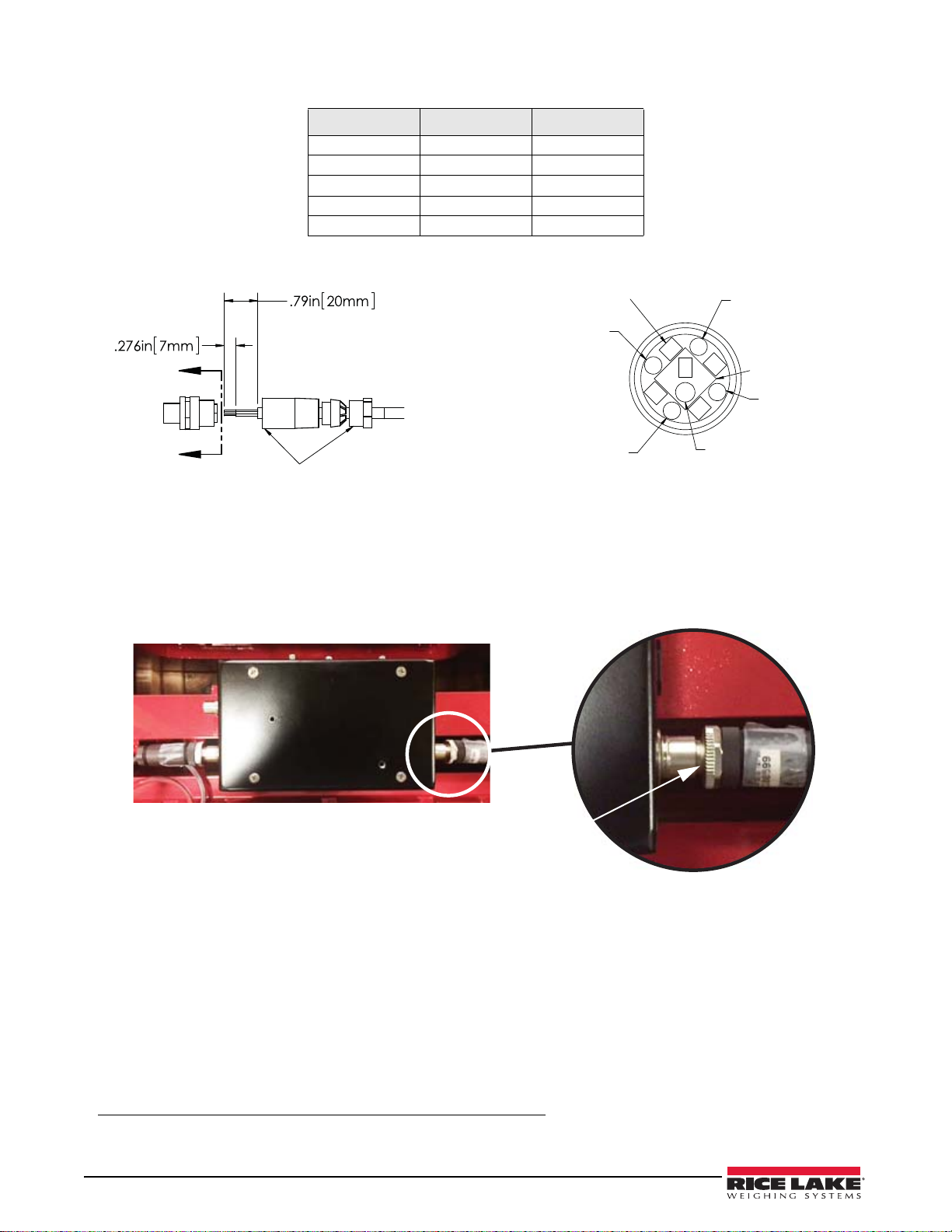
12. Add blue Loctite®1 425 to the two contact points as indicated in Figure 4.
13. Attach the load cell cables to the bottom two
• Apply Loctite.
• Hand tighten until the connection is snug,
connectors on the junction box.
plus another 1/4 turn. Only two threads should be visible.
Figure 5. Connect Load Cell Cable to junction
14. Attach the home run cable to the top side connector.
15. Install the iQube2 junction into the forklift scale
16. Open the calibration access switch cover on
17. Plug in the power cable, and turn on the
18. Calibrate the unit using Revolution
19. Connect the load cell cables to
each side.
20. Connect the coiled interface cable to
communication power box.
software.
the top of the junction.
21. Align the iQube2 junction with the bolt holes in
22. Place the cover plate in place and secure with a
Locktite® is a registered trademark of Henkel Technologies.
2 iQube2 Junction Box Upgrade
, using Loctite on the mounting screws.
the junction, set switch to the On position.
the scale and use an Allen wrench to tighten.
bolt and washer, and seal the unit.
Page 3

CLS-420 Junction Box Replacement
Figure 6. Coiled Cable Adapter
Use the following steps to replace the junction box in the CLS-420.
1. Unplug power cable from CLS-420.
23. Remove existing junction box from sca
24. Remove automotive quick conne
25. Strip wires for connection to
the new load cell connectors.
26. Follow the instructions on the packaging on
27. Wire the load cell 5-pin male connector to the following col
28. Add blue Loctite 425 to the two c
29. Attach the load cell cables to the bottom two
30. Attach the coiled cable adapter to the juncti
le carriage.
cts from load cell cables.
Turk connector, PN BS-8157-0/P69, for inserting wires.
or codes Table 1 and Figure 4.
ontact points as indicated in Figure 4.
connectors on the junction box.
on box to the top side
connector as shown in Figure 30.
31. Attach the home run cable to cable adapter and secure within the
forklift carriage.
32. Reinstall the junction box into the forklift scale, using Loctite
on
the mounting screws.
33. Plug in the power cable, and turn on the CLS-420.
34. Calibrate the unit using the CLS-420 indicator
.
6.8 iQube 2.3 Cross References
Please provide the serial number of the scale so that the Rice Lake Weighing Systems sales department can issue
the correct junction box for the model it is being purchased for.
See Table 9, to ensure the correct unit was sent if there are
The kit part number includes the appropriate load cell and ca
any issues with installation.
ble adapters required to upgrade your unit.
28" Forklift Carriage
Top Level Fork Lift Indicator iQube 2.3 Kit iQube 2.3 Junction Box
111033 420 Wired 167345 167344
111034 420 Wireless 167416, 167344
111035 920i Wired Upgrade not available 121014
111036 920i Wireless
34" Forklift Carriage
Top Level Fork Lift Indicator iQube 2.3 Kit iQube 2.3 Junction Box
96339 420 Wired 167345 167344
96340 420 Wireless 167344
96341 920i Wired Upgrade not availabl 121014
96342 920i Wireless 121014
130822 420 Wired 167356 167261
130823 420 Wireless 167261
130824 920i Wired Upgrade not available 130826
130825 920i Wireless 130826
SPX or SO WO 420 ABF 167345 167344
120911 420 ABF 167356 167261
161964 420 ABF 167341 167261
125277 CLS-M 167340 164071
Table 9. Kit Part Numbers
121014
iQube2 Junction Box Upgrade 3
Page 4

28" Forklift Carriage
230 W. Coleman St. • Rice Lake, WI 54868 • USA
U.S. 800-472-6703 • Canada/Mexico 800-321-6703 • International 715-234-9171 • Europe +31 (0)26 472 1319
www.ricelake.com www.ricelake.mx www.ricelake.eu www.ricelake.co.in m.ricelake.com
Rice Lake Weighing Systems is an ISO 9001 registered company.
© Rice Lake Weighing Systems Specifications subject to change without notice.
October 2015 PN 168876 Rev B
Top Level Fork Lift Indicator iQube 2.3 Kit iQube 2.3 Junction Box
153539 CLS-M 167340 164071
151803 CLS-420 167356 167261
132414 CLS-M2 167340 164071
156294 CLS-M3 167340 164071
164649 CLS-420 167341 167261
162279 CLS-420 167341 167261
38" Forklift Carriage
Top Level Fork Lift Indicator iQube 2.3 Kit iQube 2.3 junction
111038 420 Wired 167407
111039 420 Wireless 167407
111040 920i Wired Upgrade not available 121366
111041 920i Wireless Upgrade not available 121366
151506 420 Wireless 167407
151490 920i Wireless Upgrade not available 121366
Table 9. Kit Part Numbers
 Loading...