

Page 1
CLS-920i Cargo Lift Scale
Note
WLAN board location
in 920i indicator
Antenna location
WLAN Installation Instructions
PN 96355
Before installing this option, contact the IT administrator to obtain network communication protocol codes
and have a RS-232 communications cable or regular comm port cable ava
the 920i while installing and setting up the wireless network.
ilable to run between the PC and
The CLS-920i Cargo Lift Scale offers an optional Lantronix® WiP o r t (WLAN - Wireless Local Area Network)
wireless networking device which is installed inside the 920i indicator. This option can be used for real-time data
transmission to warehouse management systems. The Windows
®
based configuration software, DeviceInstaller is
required for installation and setup. It is available on the CD that comes with the kit. The WLAN option can be
factory installed upon request when purchasing the CLS-920i Cargo Lift scale or can be purchased separately and
installed on site.
The wireless LAN option kit contains the following:
• Pluggable wireless board (PN 97789)
• Antenna (PN 98357)
• CD containing Lantronix information (PN 72763)
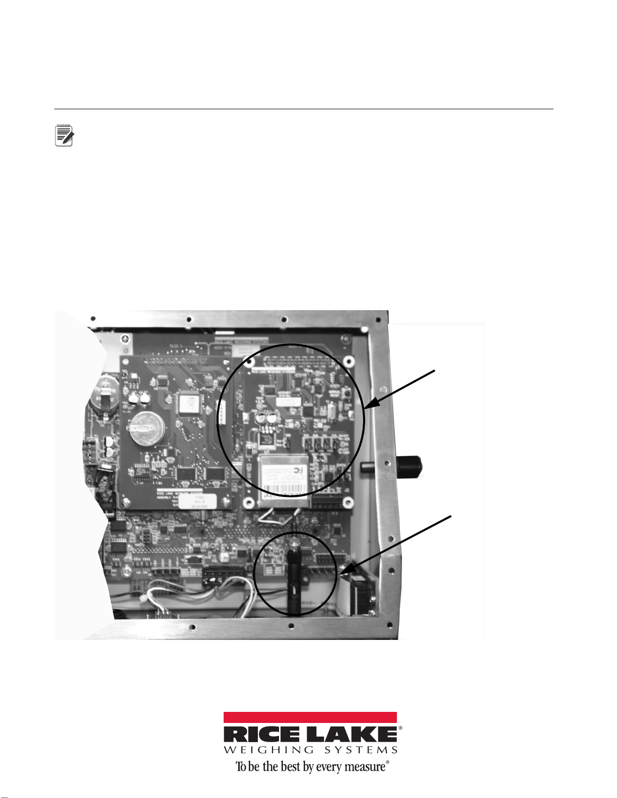
The following photo shows the WLAN ca
rd and antenna inside the 920i enclosure.
Figure 1. WLAN Board and Antenna Location Inside the 920i Enclosure
May 05, 2014 100977 Rev A
Page 2
Enclosure Disassembly
WARNING
WARNING
Wireless Antenna
LANTRONIX WiPORT
FC
Indicates
Option Card
Cable Ties
CT
CT
CT
The indicator enclosure must be opened to install the WLAN components.
The CLS-920i has no on/off switch. Before opening the unit, ensure the power cord is disconnected from
the power outlet.
1. Disconnect power to the indicator and remove unit from the forklift.
2. Place the indicator face-down on an anti-static work mat.
3. Remove the screws that hold the ba
4. Lift the backplate away from the enclos
ckplate to the enclosure body.
ure and set it aside.
Installing Option Cards
Install the WLAN option card is as follows:
Option cards are not hot-pluggable. Disconnect power to the CLS-920i before installing the WLAN option
card.
1. Ensure that power has been disconnected from the indicator.
2. Remove backplate as described in the previous section.
3. Carefully align the WLAN option card onto connector J6 (slot
4. Press down to seat the option card in the CPU board c
onnector.
5. Use the screws provided in the option kit to secure the othe
standoffs on the CPU board.
6. Set up the WLAN configuration parameters as explained on page 5.
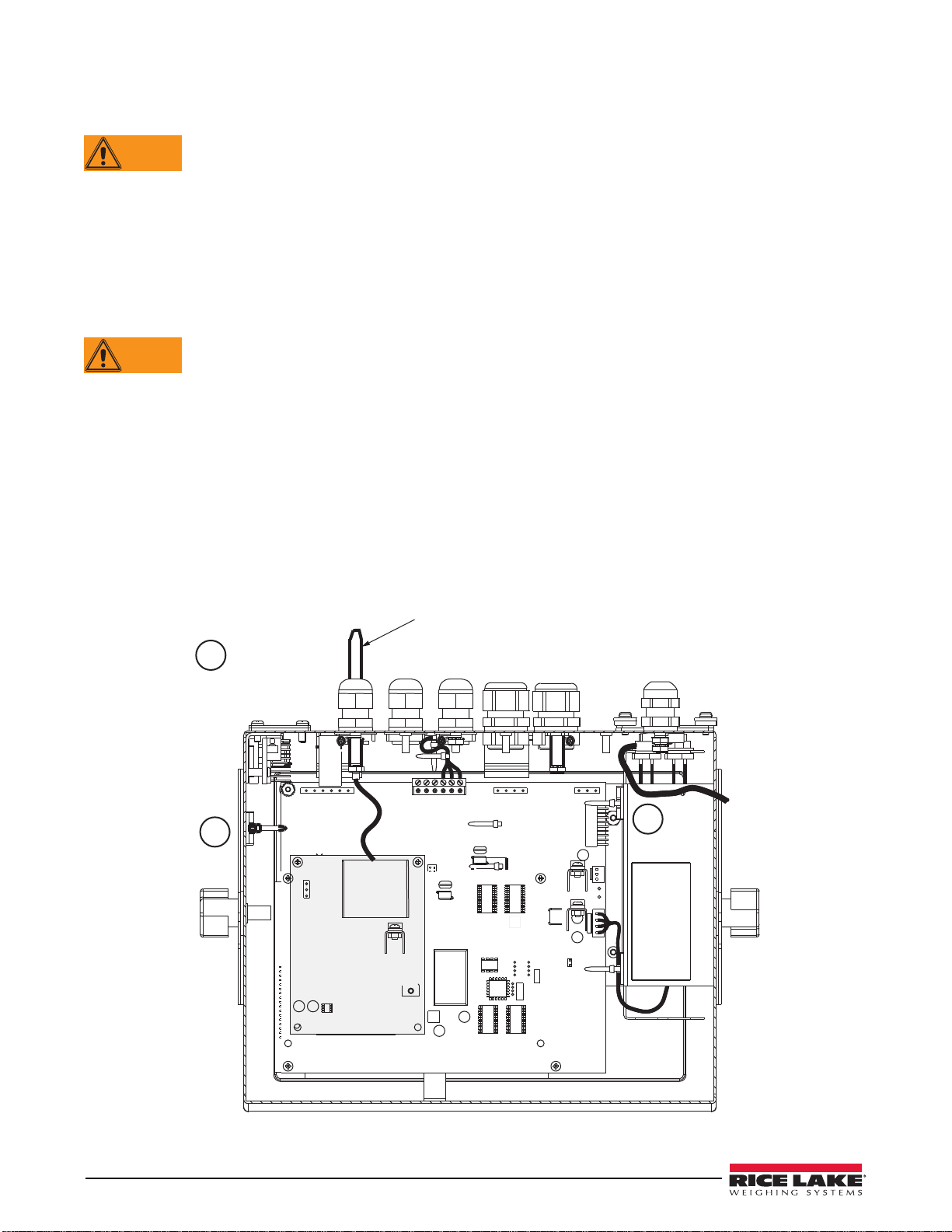
7. Make connections to the option card as required. Use ca
as shown in Figure 2.
8. When installation and configuration is complete, rea
ssemble the enclosure as shown on page 11.
2) on the CPU board.
r end of the option card to the threaded
ble ties to secure loose cables inside the enclosure
Figure 2. Installed Option Cards, Showing Secured Cables
2 CLS WLAN Installation Instructions
Page 3
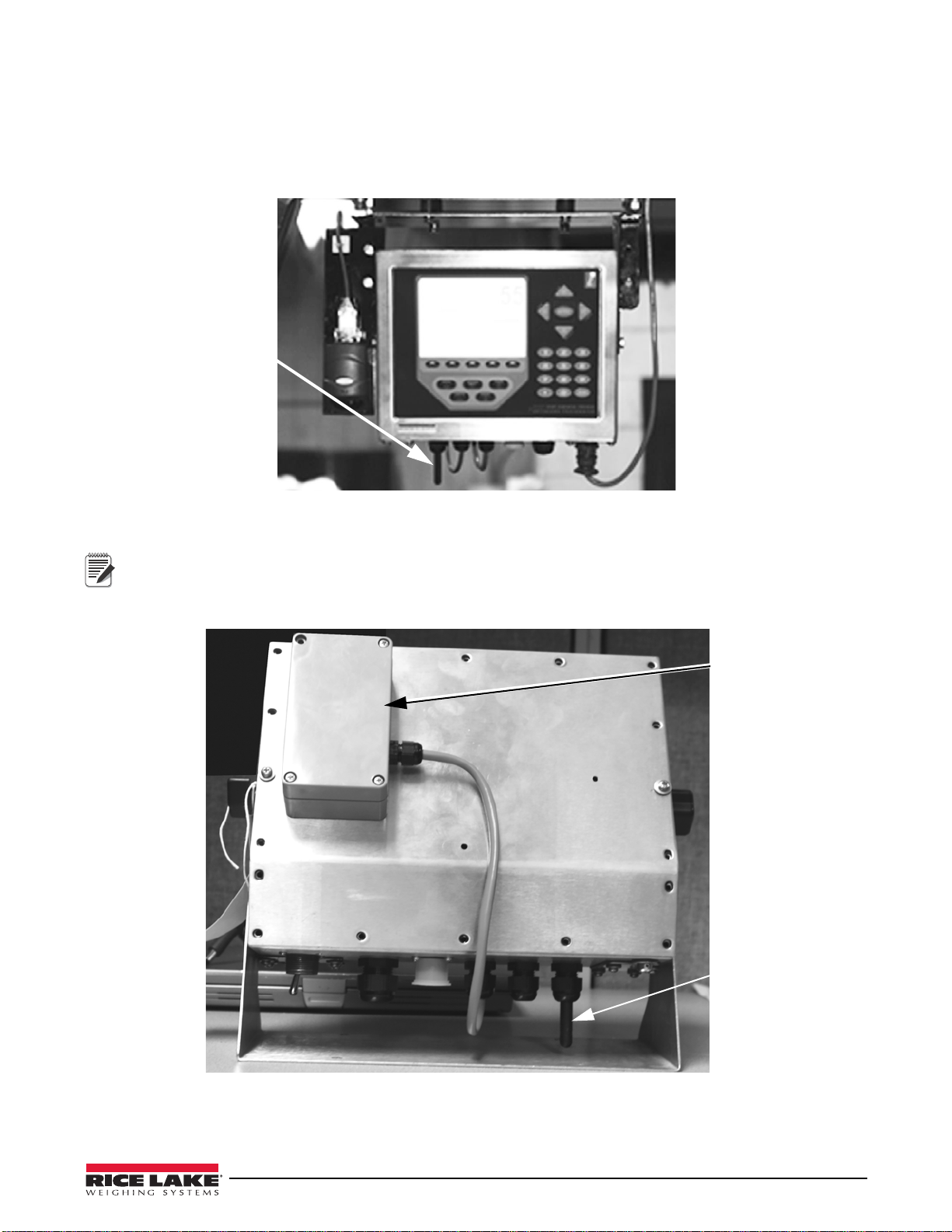
Mounting the Antenna
Antenna extending out
from the bottom of the
indicator
Place the 802.15
wireless load cell
module far enough
away from the WLAN
antenna per FCC rules
See WiPort Disclaimer
on page 13.
Place WLAN antenna
in cord grip furthest
from 802.15 wireless
load cell module.
Note
The antenna is already wired to the WLAN board.
1. Place the antenna through the smallest cord grip, furthest awa
(see Figure 3).
1. Tighten the antenna once its been pushed through the hole.
Figure 3. Location of the WLAN Antenna
The CLS-920i automatically recognizes installed option cards when the unit is powered on.
To comply with FCC regulations, the antenna should be placed as far as possible away from the 802.15
wireless load cell kit module. The following photo shows the 80
antenna locations on the indicator.
y from the 802.15 wireless load cell kit
2.15 wireless load cell module and WLAN
Figure 4. Location of 802.15 Wireless Load Cell Module and WLAN Antenna Location
3
Page 4
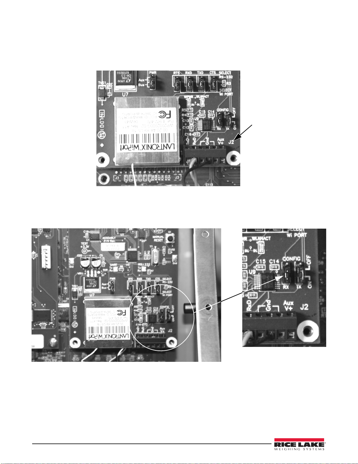
Wireless Configuration via Serial Mode
Connect a cable into the J2
connector of the installed
WLAN option to a PC
Wiring is as follows:
TxD = J2, Pin 1
RxD = J2, Pin 2
Gnd = J2, Pin 3 or 4
The CLS-920i must configure so that it can communicate on the network. WiPort (WLAN) is configurable using a
PC and a terminal program (like Windows XP Hyperterminal) to access the device serial port locally.
To configure the WiPort (WLAN option), connect a serial cable from the J
option card to a PC.
Figure 5. WLAN Serial Cable Wiring From the WLAN Option Card
2 connector of the installed WLAN
Jumpers
There are two configuration jumpers located on the WLAN option board. See Figure 6. These jumpers must be set
to the ON position to configure the WLAN option.
Figure 6. Configuration Jumper Location on WLAN Option Board
4 CLS WLAN Installation Instructions
Page 5
Set WLAN Configuration Parameters
Note
Once the configuration jumpers are in the ON position, use the following steps to make the necessary settings for
the WLAN option.
Not all devices display information in the same manner and depending on the IT department’s software choice
for configuring the WLAN option, the screens di
If using Lantronix DeviceInstaller, additional infor
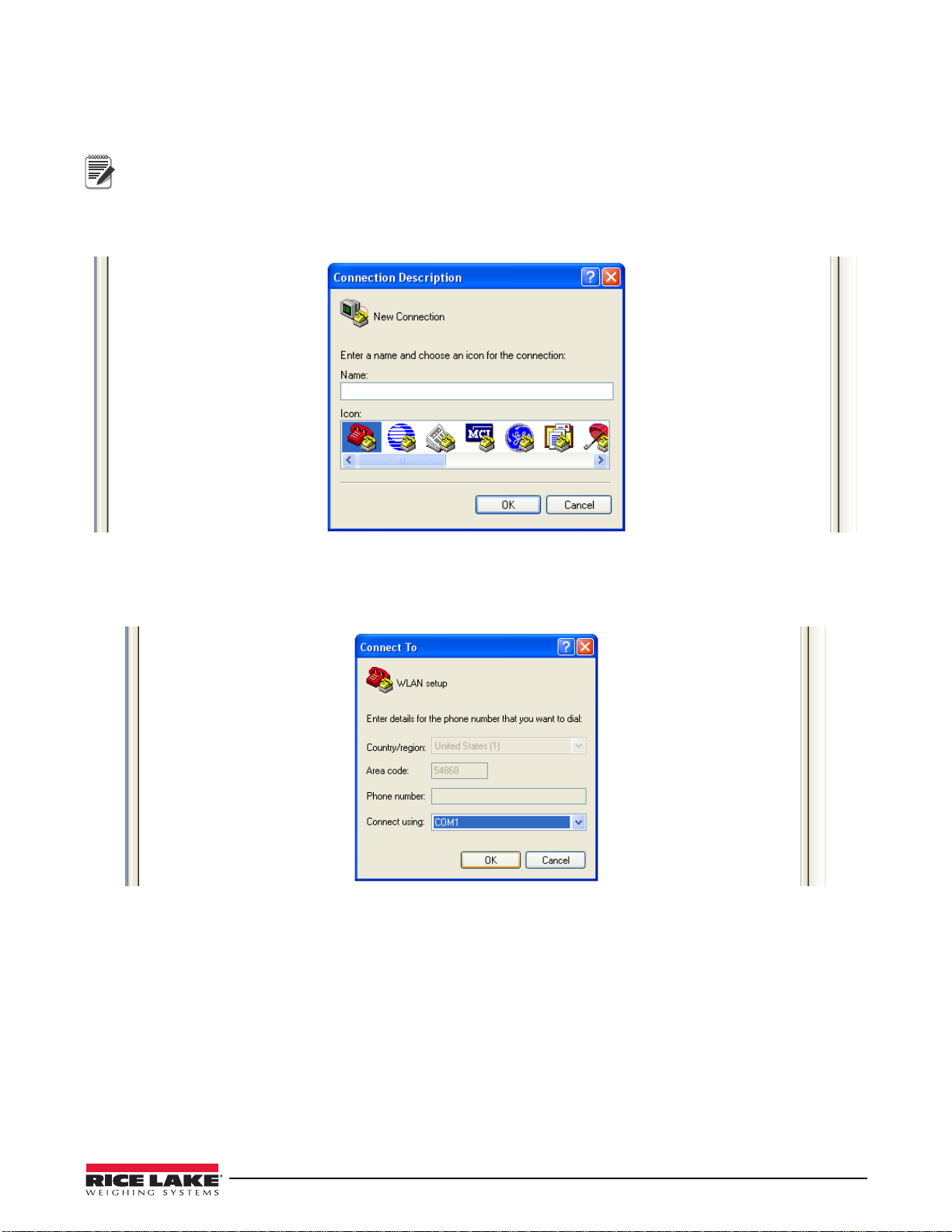
1. Select the Hyperterminal program on the PC.
2. Enter a name and choose an icon for the connection and press
Figure 7. Hyperterminal Connection Description Screen
3. Select an option for connection.
4. Select the comm port connect
5. Press
OK.
ed to the serial cable
splayed may be different.
mation can be accessed at www.lantronix.com.
OK.
Figure 8. Connect To Screen
5
Page 6

6. Comm port properties must be set as shown in Figure 9.
Manual Reset Button
Note
Figure 9. Comm Port Properties Screen
The WLAN configuration port uses the following settings:
• Baud Rate - 9600
• 8 Bits
• No Parity
•1 Stop Bit
• No Flow Control
7. Make required changes and press
OK.
8. Reset the WLAN option card by pressing the manual reset button.
9. Immediately upon release enter three lowercase
x characters (xxx) at the same time. The manual reset
button location is shown in Figure 10.
Figure 10. Manual Reset Button Location on WLAN Option Card
The easiest way to connect is to hold down the x key on the PC’s keyboard until the manual reset button is
released and the PC screen displays the MAC address and s
be done within three seconds o
6 CLS WLAN Installation Instructions
oftware version as shown in Figure 11. This must
f resetting the WLAN option.
Page 7
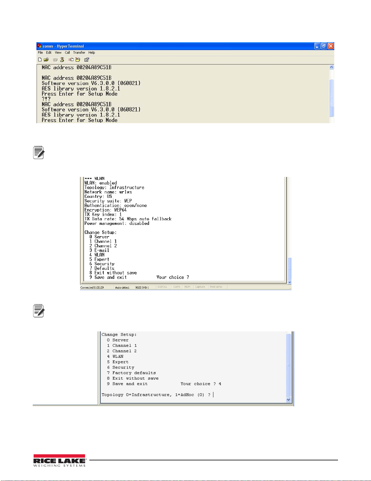
Upon a successful connection, the following information is displayed.
Note
Note
Figure 11. Display Information for Setup Mode
10. To enter Setup Mode, press Enter within five seconds.
The connection will fail if Enter is not pressed within the five second time limit. The configuration settings
display, followed by the setup menu options. If
this happens, repeat Step 8 through Step 10.
11. Select an option on the menu by entering the number of the option in Your Choice? field and press Enter.
Example: To set up the WLAN options, press 4 and press Enter as shown in Figure 12.
Figure 12. Change Setup Screen
View the current configuration by pressing Enter from the Change Setup menu. To enter a value for a
parameter, type the value and press Ent
parameters).
er. To confirm a current value, press Enter (without inputted
12. Enter the desired Topology for the WLAN option.
Figure 13. Topology Screen
The two choices are:
• 0 = Infrastructure
• 1 = AdHoc.
Select
0 and press Enter.
7
Page 8
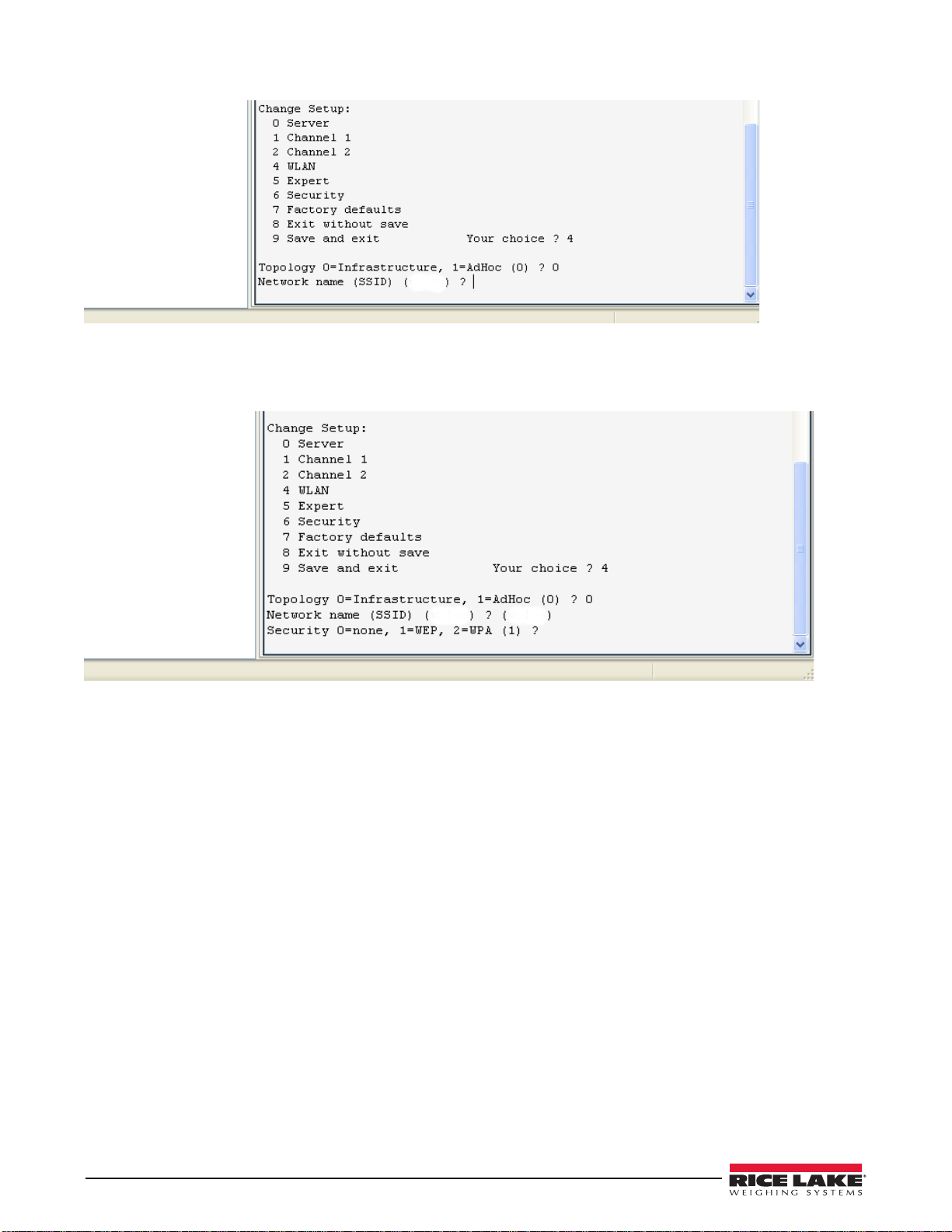
13. The next menu choice is Network Name as shown in Figure 14.
Figure 14. Network Name Screen
14. Enter the wireless network name as the menu choice and press Enter. This identifies the network that the
wireless option will run on.
15. The next step is to select a level of se
curity as shown in Figure 15.
Security levels include:
• 0 = None
• 1 = WEP (Equivalence Protection)
•2 = WPA
Select
1 and press Enter.
Figure 15. Security Level Select Screen
8 CLS WLAN Installation Instructions
Page 9

16. The next step is to set the authentication level for the configuration as shown in Figure 16.
Note
Figure 16. Authentication Screen
Authentication choices are:
•0 = open/none
• 1 = Shared
Select
0 = open/none and press Enter.
17. Select the correct encryption next. Choices
are WEP64 and WEP128 as shown in Figure 17.
Select 1 = WEP64 as the default parameter and press Enter.
Figure 17. Encryption Screen
18. Display current key? is displayed. Press N and press Enter.
Figure 18. Display Current Screen
Select Yes (Y) for the display current key option to show the currently configured key/passphrase.
9
Page 10

Figure 19. Change Key Screen
19. Select the data rate and press Enter.
20. The screen automatically goes to end the sc
reen which gives the choice to Save and Exit (9), see Figure 20.
By selecting that choice, and pressing Enter, the WLAN parameters are saved and the screen is grayed out
Figure 20. Save and Exit Screen
Once all of the data is saved, the jumpers must be switched back to the OFF position (Figure 6) to exit out of the
configuration mode.
All wireless data can now be accessed and viewed on the PC.
10 CLS WLAN Installation Instructions
Page 11
Enclosure Reassembly
5PSRVFCBDLQMBUFTDSFXT
UPJOMC/N
Important
Important
Once cabling is complete:
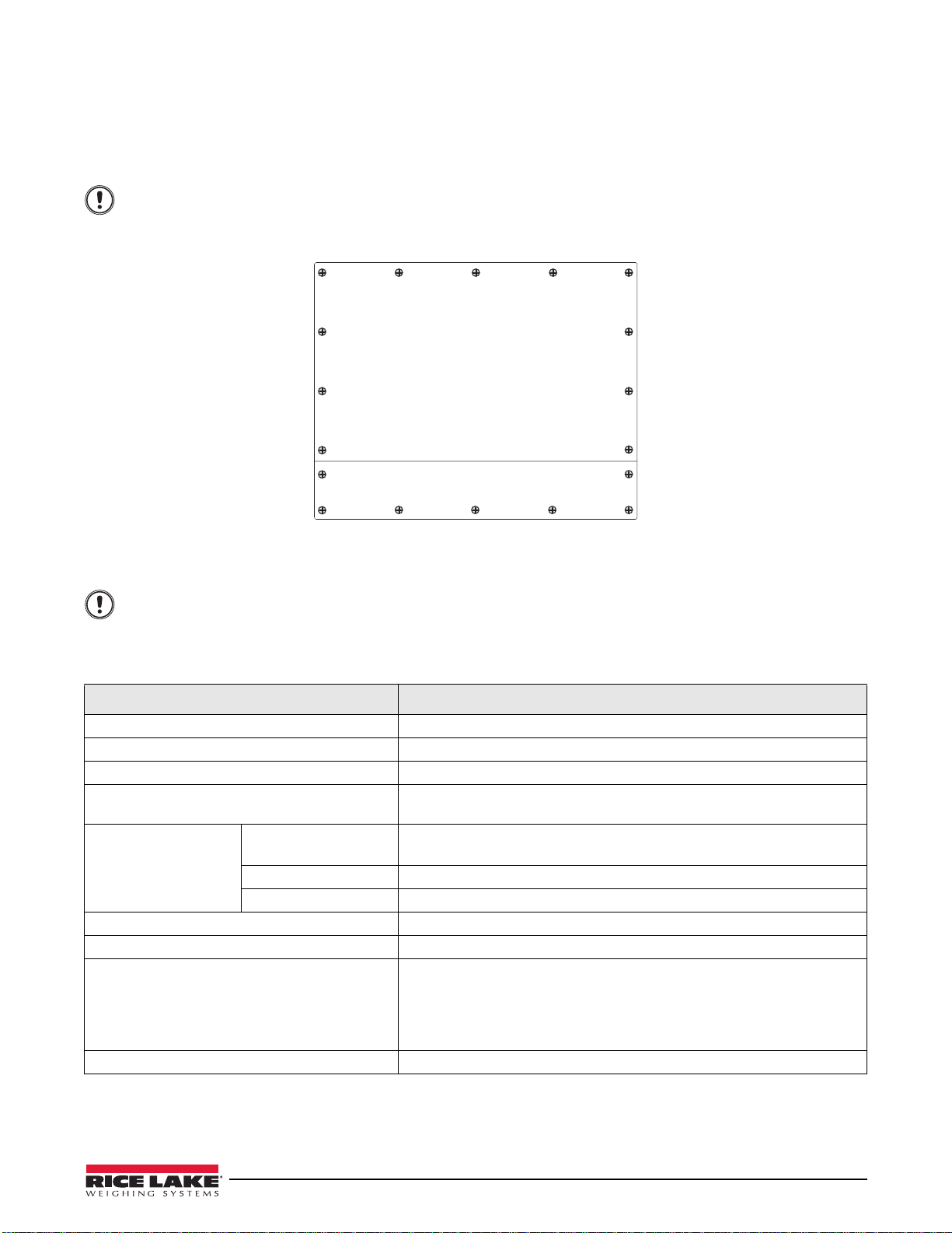
1. Position the backplate over the enclosure.
2. Reinstall the backplate screws.
Use the torque pattern shown in Figure 21 to prevent distorting the backplate gasket. Torque screws to
15 in-lb. (1.7 N-m).
Figure 21. CLS-920i Enclosure Backplate
Torqued screws may become less tight as the gasket is compressed during torque pattern, therefore a
second torque is required using the same pattern and torque value.
WiPort Wireless Specifications
Category Description
Network Standards IEEE 802.11b; IEEE 802.11g
Frequency Range 2.412 - 2.484 GHz
Antenna Connector 1, no diversity supported
Data Rates 1, 2, 5.5, 11Mbps (802.11b)
6, 9, 12, 18, 24, 36, 48, 54Mbps (802.11g)
Radio Number of Selectable
annels
Ch
Modulations OFDM, DSSS, DBPSK, DQPSK, CCK, 16QAM, 64QAM
Antenna Connector 1
Security WEP 64/128, WPA-PSK, TKIP, AES end-to-end encryption
Maximum Receive Level -10 dBm (with PER < 8%)
Receiver Sensitivity -72 dBm for 54Mbps
WLAN Power and Link LED Current Max: 4 mA
Table 1. WiPort Wireless Specifications
Up to 14 channels. Profiles available will include USA, France, Japan, Spain,
Canada and "other" (multiple countries).
-87 dBm for 11Mbps
-89 dBm for 5.5Mbps
-90 dBm for 2.0Mbps
-92 dBm for 1.0Mbps
11
Page 12

WiPort Technical Data
Category Description
CPU, Memory Lantronix DSTni-EX 186 CPU, 256 KB zero wait state on chip SRAM,
ROM
Firmware Upgradeable via TFTP and serial port
Reset Circuit Reset In is low active. Min
Serial Interface CMOS (Asynchronous) 3.
Rate is software selectable (300 bps to 921600 bps)
Serial Line Formats 7 or 8 data bits, 1-2 stop bits, par
Modem Control DTR, DCD
Flow Control XON/XOFF (software), CTS/RTS (hardware), none
Network Interface Wireless 802.11b, 802.11g and 10/100 Ethernet
Protocols Supported ARP, UDP, TCP, Telnet, ICMP, SNMP, DHCP, BOOTP, Auto IP, HTTP, SMTP, TFTP
Media Access Control CSMA/CA with ACK
Frequency Range 2.412-2.484 GHz
Range Up to 328 feet (100m) line of sight
Modulation Techniques OFDM
Transmit Output Power 14 dBm + 1.5 dBm/-1.0 dBm
Peak Supply Current at 3.3V 650 mA
Management Internal web server, SNMP (read only)
Security Password protection, locking featur
Internal Web Server Serves web pages
Weight 29 grams
Material Metal shell
Temperature Operating range: -30° C to +70° C (-22° F to 158° F)
Storage range: -40° C to +85° C (-40° F to +185° F)
Warranty 2-year limited warranty
Included Software
Windows
®
98/NT/2000/XP based DeviceInstaller configuration software and Windows based
Comm Port Redirector, DeviceInstaller, Web-Manager
Lantronix web site: http://
imum reset pulse width is 2 ms at IIL = -500 aA
3V-level signals
ity: odd, even, none
DSSS
CCK
DQPSK
DBPSK
64 QAM
16 QAM
Serial login, Telnet login
DeviceInstaller software
es, 64/128 bit WEP, WPA-PSK, End-to-End AES
Storage capacity: 1.2 MB
www.lantronix.com/
2048 KB flash, 16 KB Bott
12 CLS WLAN Installation Instructions
Table 2. WiPort Technical Data
Page 13

WiPort Disclaimer
Note
Note
This equipment has been tested and found to comply with the limits for a Class B digital device, pursuant to Part 15
of the FCC rules. These limits are designed to provide reasonable protection against harmful interference in a
residential installation. This equipment generates, uses, and can radiate radio frequency energy and, if not installed
and used in accordance with the instructions, may cause harmful interference to radio communications. However,
there is no guarantee that interference will not occur in a particular installation. If this equipment does cause
harmful interference to radio or television reception, which can be determined by turning the equipment of f and on,
the user is encouraged to try to correct the interference by one of the following measures:
• Re-orient or relocate the receiving antenna
• Increase the separation between the equipment and the receiver
• Connect the equipment into an outlet on a circuit dif
• Consult the dealer or an experienced
radio/tv technician for help
This device complies with Part 15 of the FCC rules. Operation is subj
device may not cause harmful interference, and (2) this device must accept any interference received, including
interference that may cause undesired operation.
This device is intended only for OEM integrators. The OEM in
issues.
Labeling of the End Product
The label of the end product integrating this module must clearly indicate that the end product contains an FCC
approved RF module. The format of such statement could be Contains Transmitter with FCC ID: R68WIPORTG or
something similar.
RSS-GEN Sections 7.1.4 and 7.1.5 Statement for Devices with Detachable Antennas
This device has been designed to operate with the antennas listed in the certificate, and having a maximum gain of
5 dB. Antennas not included in this list or having a gain greater than 5 dB are strictly prohibited for use with this
device. The required antenna impedance is 50 ohms.
To reduce potential radio interference to
other users, the antenna type and its gain should be so chosen that the
equivalent insotropically radiated power (EIRP) is not more than that required for successful communication.
ferent from that to which the receiver is connected
ect to the following two conditions: (1) This
tegrator should be aware of the following important
Integration Note
(a) This module is authorized under limited module approval specified to mobile host equipment. So, the antenna
must be installed such that 20 cm is maintained between the antenna and the user.
(b) The transmitter module may not be co-located with any
As long as the two conditions above are met, further transmission
other transmitter or antenna.
testing will not be required. However, the OEM
integrator is still responsible for testing their end product for any additional compliance requirements required with
this module installed (for example, digital device emission, PC peripheral requirements, etc).
In the event that these conditions cannot be met (for example) certain laptop configurations, general purpose
PCMCIA or similar card, or location with another transmitter), then the FCC authori
considered valid and the FCC ID cannot be used on the final product (including the transmitter) and obtaining
a separate FCC authorization.
Changes or modifications to this device not explicitly approved by Lantronix will vo
operate this device.
zation is no longer
id the user’s authority to
13
Page 14

230 W. Coleman St. • Rice Lake, WI 54868 • USA
U.S. 800-472-6703 • Canada/Mexico 800-321-6703 • International 715-234-9171 • Europe +31 (0) 88 2349171
www.ricelake.com www.ricelake.mx www.ricelake.eu www.ricelake.co.in m.ricelake.com
© Rice Lake Weighing Systems 05/2014 PN 100977 Rev A
 Loading...